

Page 1
Installation Manual
Installation, Operation & Maintenance of the ZECV
Analog Pressure Controller
General Description
When applying Zcom diusers in an changeover/
bypass application with a constant volume rooftop
unit, provisions must be made to control duct static
pressure. The duct static pressure is typically
controlled by a system bypass damper installed o
of the supply duct, and controlled from a static
pressure tap installed 2/3 down the main duct.
Figure 2 illustrates a re commended installation of
the bypass damper to maximize mixing of the
bypass air with the return air. This location of the
bypass minimizes the opportunity for developing
hot or cold spots in the rooftop.
Installation Instructions
ZECV-IOM-1.0 3-1-03
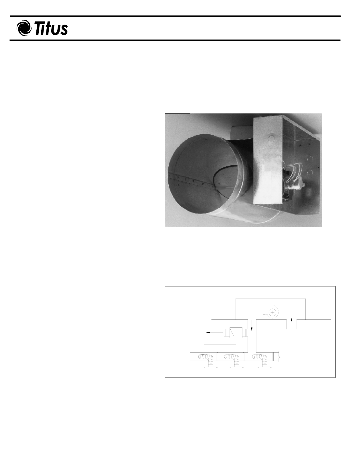
Figure 1. ZECV
These instructions are intended only as a basic
guide for the installer. They do not assure
compliance with local codes. Consult the
authorities having jurisdic tion be
terminal.
fore installing this
Receiving Inspection
After unpacking the pressure controller, check it for
shipping damage. If any shipping damage is found,
report it immediately to the delivering carrier.
Supporting the Terminal
The basic control is light enough so that it can be
supported by the duct work in which it is installed.
Where the accessory modules such as coils,
attenuators or multiple outlets are included, the
assembly should be supported directly. Use the
support method prescribed for rectangular duct in
the job specications.
Duct Connections
Slip the inlet duct over the inlet collar.
The diameter of the inlet duct in inches must be
equal to the listed size if the terminal: e.g., a duct
that actually measures 8 in ches must be tted to a
size 8 terminal. Attach the
by using standard SMACNA slip and drive
connection method. Fasten and seal all
connections by the method prescribed by the job
specications.
rectangular outlet duct
Figure 2.
Static
Pressure
Tap
Bypass
Air
Constant Volume Rooftop Unit
Supply
Air
ZECV
Return
Air
Zcom
Page 2

ZECV-IOM-2.0 3-1-03
Field Wiring Instructions
Inspection
Factory mounted controls and accessories are mounted
inside the sheet metal enclosure located on the side of
the terminal. Remove the cover and inspect all
components for visual damage.
Power and Supply
Analog electronic controls require 24 VAC -15/+20
percent power supply. Allow 14 VA for the controller.
Factory supplied transformers are available with supply
voltages of 277V, 240V, 208V, or 120V. Field supplied
transformers can be mounted inside the control box.
Attach the 24 volt leads to terminals 9 and 10 on the
controller (See Figure 3).
Single Transformer Wiring
The same 24 VAC transformer may be used to power
the controller plus control relays, contractors and/or
valves on a terminal. For single transformer wiring see
figure 3.
Multiple Loop Wiring
If multiple controllers are looped together in a single
circuit using a common transformer, wire all #9
connections together, and all #10 connections together.
If the transformer secondary is connected to earth
ground, this lead must also be connected to terminal #9.
ALWAYS OBSERVE PHASING!
CAUTION: NEVER connect power to the controls until
all wiring has been installed. ALWAYS disconnect power
to the controls before servicing the unit controls or
accessories. DO NOT connect line voltage to the
controller or other unit components.
Balancing
The following guidelines are recommended when
balancing a constant volume rooftop unit and Zcom
diffuser system.
1. Adjust rooftop to supply cooling or heating during
the balance. The Zcom diffuser has three modes of
operation; cooling, heating and ventilation. If the
supply air temperature is between the heating and
cooling setpoints, the Zcom will operate in the
ventilation mode and go to the ventilation damper
position of 50% closed. Therefore, to properly
balance the system, the rooftop unit must be in either
cooling or heating.
2. Drive the Zcom diffusers fully open with the
Zapper, shown on the Zapper as “CL Open” or “HT
Open” (CL for cooling mode and HT for heating
mode), or power down all Zcom diffusers which will
return the Zcom’s to the fully open position.
3. Balance each diffuser for the required design air
flow.
The next steps apply to balancing the bypass damper to
maintain duct static pressure.
1. Command all Zcom diffusers to the minimum
position except one Zcom master, which is to remain
fully open. The Zapper is used to command the Zcom
to the minimum position by pushing the down arrow
selector button until “CL Close” or “HT Close” (CL for
cooling mode and HT for heating mode) is displayed
on the Zapper.
2. Set the bypass damper by adjusting the ZECV
constant volume module to the desired static
pressure as measured at the static pressure tap
installed 2/3 down the main duct. The TITUS ZECV
has a time delay of approximately five minutes before
reacting to any adjustment.
NOTES:
Consult local codes for specific types of wires and
enclosures required for low voltage wiring.
Troubleshooting information is found on page.
All wiring diagrams shown in this manual show single
transformer wiring.
Page 3

Figure 3.
POWER
SUPPLY
CONDUCTORS ONLY
{
12
COM
WHT
24 VAC
USE COPPER
L1
N
RED
GREEN
13
RED - CCW - GRN
CLOSE
GRN - CW - RED
ZECV-IOM-3.0 3-1-03
BLACK
WHITE
DISC SWITCH
(OPTIONAL)
14
BLACK
WHITE
208V
240V
TRANSFORMER
BLK
RED
ORN
240V TRANSFORMER
CAP UNUSED
TRANSFORMER LEAD
YELLOW
24V120/277V
BLUE
YELLOW
24V
BLUE
BLUE
YELLOW
SEE MOTOR DETAIL BELOW
CONTROLLER/ACTUATOR
LINK DAMPER CLOSED, CW TO OPEN
HI LO
8
9
10
11
12
13
{
14
7
6
5
4
3
2
1
BLUE #18
WHITE #18
ORANGE #18
WIRING DETAIL FOR CLOCKWISE TO OPEN ROTATION
FOR PRESSURE CONTROL
RED
GREEN
14
13
12
RED - CCW - GRN
COM
CLOSE
WHT
24 VAC
GRN - CW - RED
WIRING DETAIL FOR CLOCKWISE TO OPEN ROTATION
FOR BYPASS CONTROL
TUBE W/RED STRIPE (HI)
INLINE FILTER
CLEAR TUBING
TEE
STATIC PRESSURE
TAP (FIELD INSTALLED)
BYPASS PRESSURE CONTROL OR
LOCATED DOWNSTREAM FOR
DISCHARGE PRESSURE CONTROL
STATIC PRESSURE TAP:
LOCATED UPSTREAM FOR
Replacement Parts
DESCRIPTION MODEL # TITUS PART #
Controller-Actuator-Sensor
(Sizes 4–10) CEP-4011 100277-01
(Sizes 12–16) CEP-4012 100277-02
System Control Modules
Constant Volume
Pressure Controller REE-1004 101711-01
INCR
R456
CONSTANT VOLUME
MODULE
ORANGE #18
BLUE #18
WHITE #18
CAUTION:
ELECTRIC SHOCK MAY RESULT.
DISCONNECT POWER SUPPLY
PRIOR TO SERVICING UNIT.
DESCRIPTION TITUS PART #
Transformers
120/24V 50VA 100058-01
208/24V 50VA 100575-01
240/24V 50VA 100575-01
277/24V 50VA 100066-01
480/24V 50VA 101003-01
24V/24V 50VA 101066-01
NOTES:
Vendor part numbers may vary by date of manufacture. Series 4000 controls
and accessories began with TITUS Factory No. 37337 (1988). Series 4000
controllers and modules must be matched together. All other series are
interchangeable.
All valve sizes are National Pipe Thread (NPT). Valves include one female
and one male union.
Proportional control water valves may be used as proportional with above
listed modules or as two-position with standard reheat module.
Water control valves and actuators are shipped separately from terminal unit
to reduce damage.
Primary Damper Assy.
Size 4–5–6” 301820-01
Size 7” 301820-02
Size 8” 301820-03
Size 9” 301820-04
Size 10” 301820-05
Size 12” 301820-06
Size 14” 301820-07
Size 16” 301820-08
Damper Shaft Extension
Short Stub-ALL 703003-01
Long Extension
Sz. 4–6, 14, 16 703003-02
Sz. 7–12 703003-03
Shaft Bearing 703249-01
Page 4

ZECV-IOM-4.0 3-1-03
Service Procedure Check Sheet
Voltage Range
Terminal Connectors #9, #10 #11, #12 #13, #14
Tag Location
I. Verify all wires are tightly secured to the proper terminals. CAUTION: Do NOT touch terminals with a screwdriver while
power is on.
II. Verify CONTOLLER/ACTUATOR operation:
A. Observe motor operation through observation window. It should be rotating frequently and rocking back and forth in
response to changes in air flow.
B. Observe arrow on the end of the damper shaft. Verify that damper rotates a full 90 degrees on call from full
pressure.
C. Verify the setscrew is secure to the damper shaft at the proper location. Do NOT alter factory setting. CAUTION:
Motor may be hot to the touch. (May be up to 150° F).
III. PROBLEMS AND POSSIBLE SOLUTIONS:
A.Power supply (#9 and #10) out of range -
- If ZERO, turn power on the read again.
- If power is on, determine reason for damage,
Repace faulty or undersized transformer.
B. Damper remains full OPEN-
- Verify sufficient primary air flow to terminal.
- Check for loose damper set screw.
- Verify damper is positioned correctly.
- Verify limits are not set too high at the thermostat.
C. Damper remains full CLOSED-
- Check continuity for broken sensor wires.
- Verify damper set screw is secure.
- Verify damper position is correct.
- Verify damper is free to turn.
D. Damper remains STOPPED (won’t open or close)
- Verify 24 VAC on motor that should be rotating.
- Reset thermostat slider and check opposite motor for 24 VAC.
- Verify damper is free to turn.
- Replace faulty controller/actuator.
Thermostat
Setting
20.4-28.8 0 or 24 0 or 24
Power Supply
Supply Voltage, AC
CCW
Motor
CW
Motor
 Loading...