

Page 1
Installation Manual
TITUS I, II, and IIA Pneumatic Controls
Installation, Operation, and Maintenance Manual
Adjusting Minimum and Maximum Air Flow
PNEU-IOM-1.0 5-2-05
Airflow limits are printed on the label on the
optional controller cover (or the side of the
terminal) and the side of the controller (Figures
2 and 3).
If field adjustment becomes necessary, follow
the procedure outlined below.
AIR FLOW ADJUSTING PROCEDURES FOR
ALL CONTROLLERS
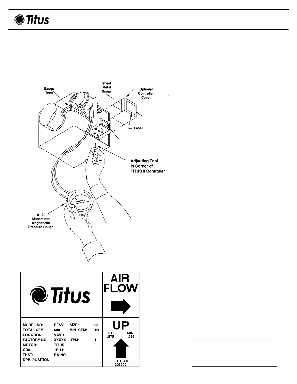
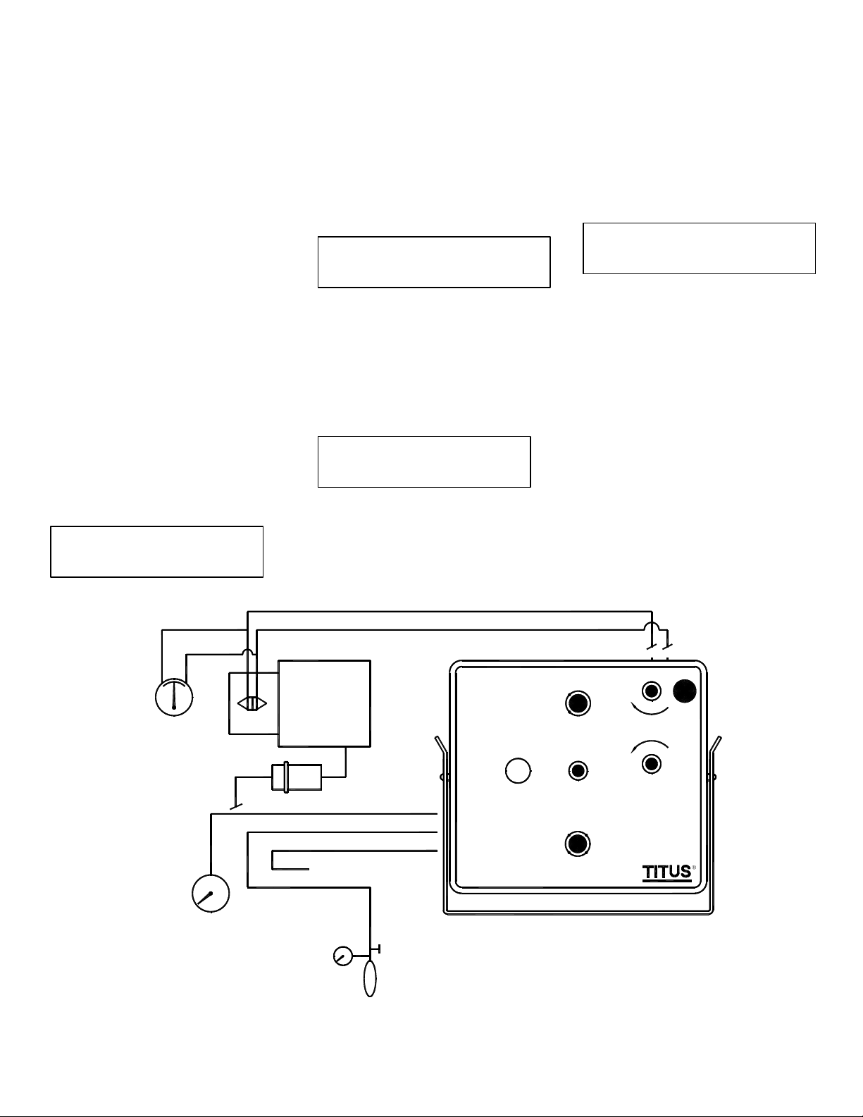
Figure 1. Adjusting Air Flow
(See Figure
3)
(Label, See Figure 3)
1. Remove the optional controller cover
(Figure 1).
2. The action of the controller must match the
settings printed on the labels (Figures 2
and 3).
a. TITUS I—Direct acting, normally
open, (control color—beige).
b. TITUS I—Reverse acting, normally
closed, (control color—gray).
c. TITUS IIA—Direct or reverse acting
thermostat. No adjustment necessary.
d. TITUS IIA—Verify setting on damper
dial is correct (N.O. or N.C.).
e. TITUS II—Check thermostat and
damper compatibility selectors, verify
that settings are as marked on the
label.
3 Remove the caps from the tees in the HI
and LO tubes (red and green stripe).
Connect a manometer gauge to both tees
(gauge with a 0 to 2 inch scale is
recommended).
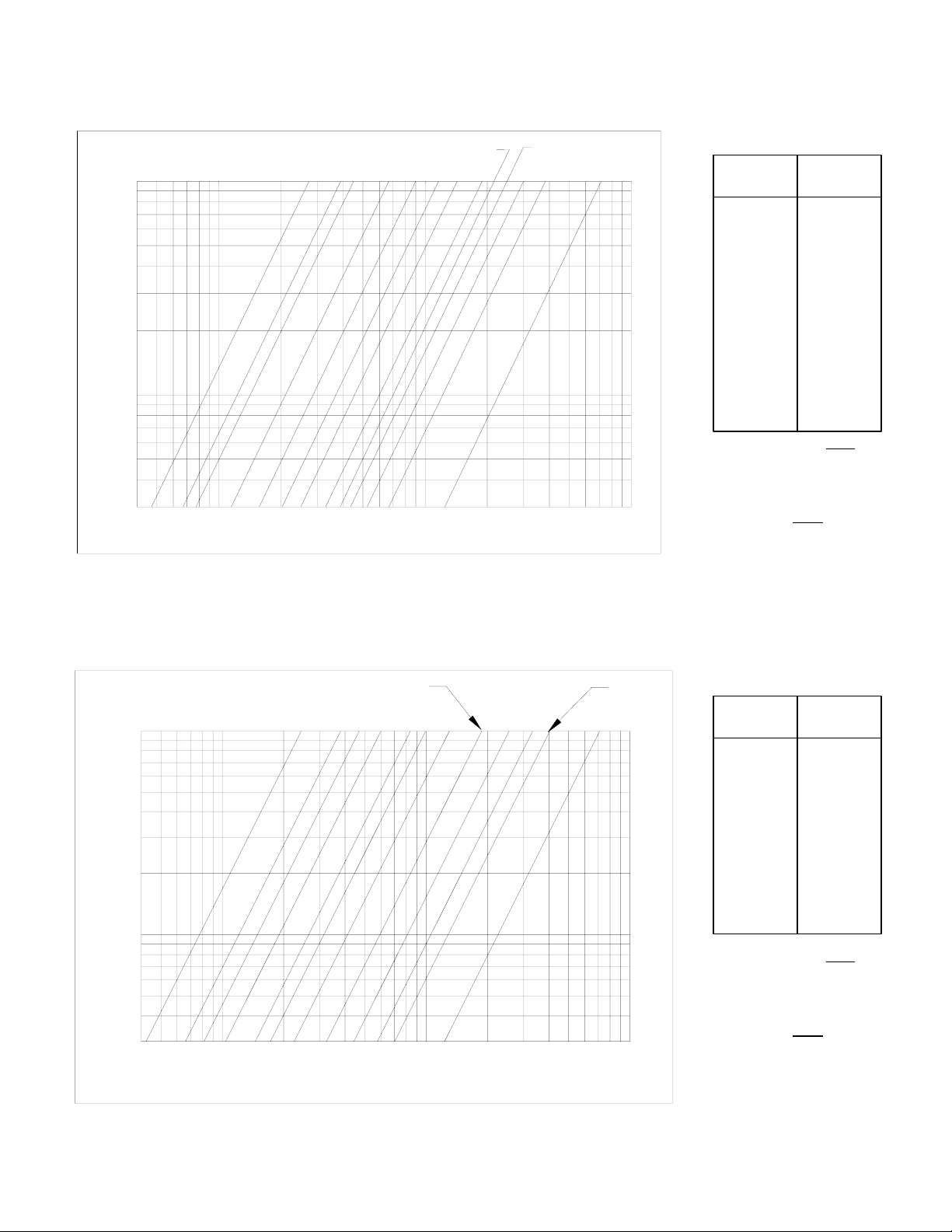
4. Refer to the calibration curve for
terminal being serviced (Page 8). From the
curve read the differential pressure across
the sensor for the required airflow.
5. For instructions to readjust the control refer
to:
a. TITUS I See page 3.
b. TITUS IIA See page 4-5.
c. TITUS II See page 6-7.
d. For dual duct terminals, see document
PNEU-DD-IOM.
e. Quick-Check. See page 2.
6. After the flow rates are adjusted:
a. Replace the thermostat connection to
the controller.
b. Remove the gauge and replace the
caps on the tees.
c. Replace the optional controller cover.
the size
Figure 2. Unit Label
MODEL NO: PESV
TOTAL CFM: 600
TITUS II NO RA COOL
MIN. CFM: 160
FACTORY NO:XXXXX
Figure 3. Controller Label
SIZE: 08
VP: .410
VP: .030
ITEM: 1
Page 2
Quick-Check Procedure for TITUS I, II, and IIA Controllers
PNEU-IOM-2.0 5-2-05
Preparing for Calibration
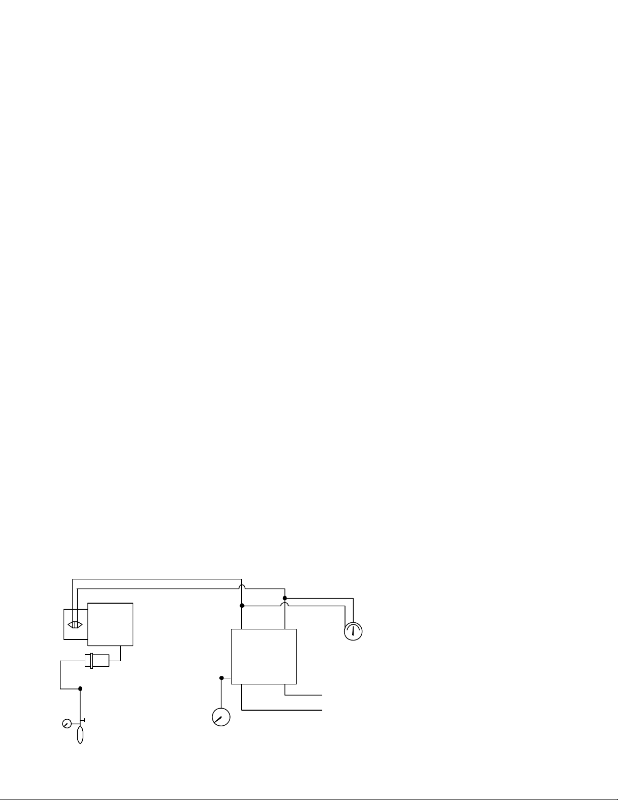
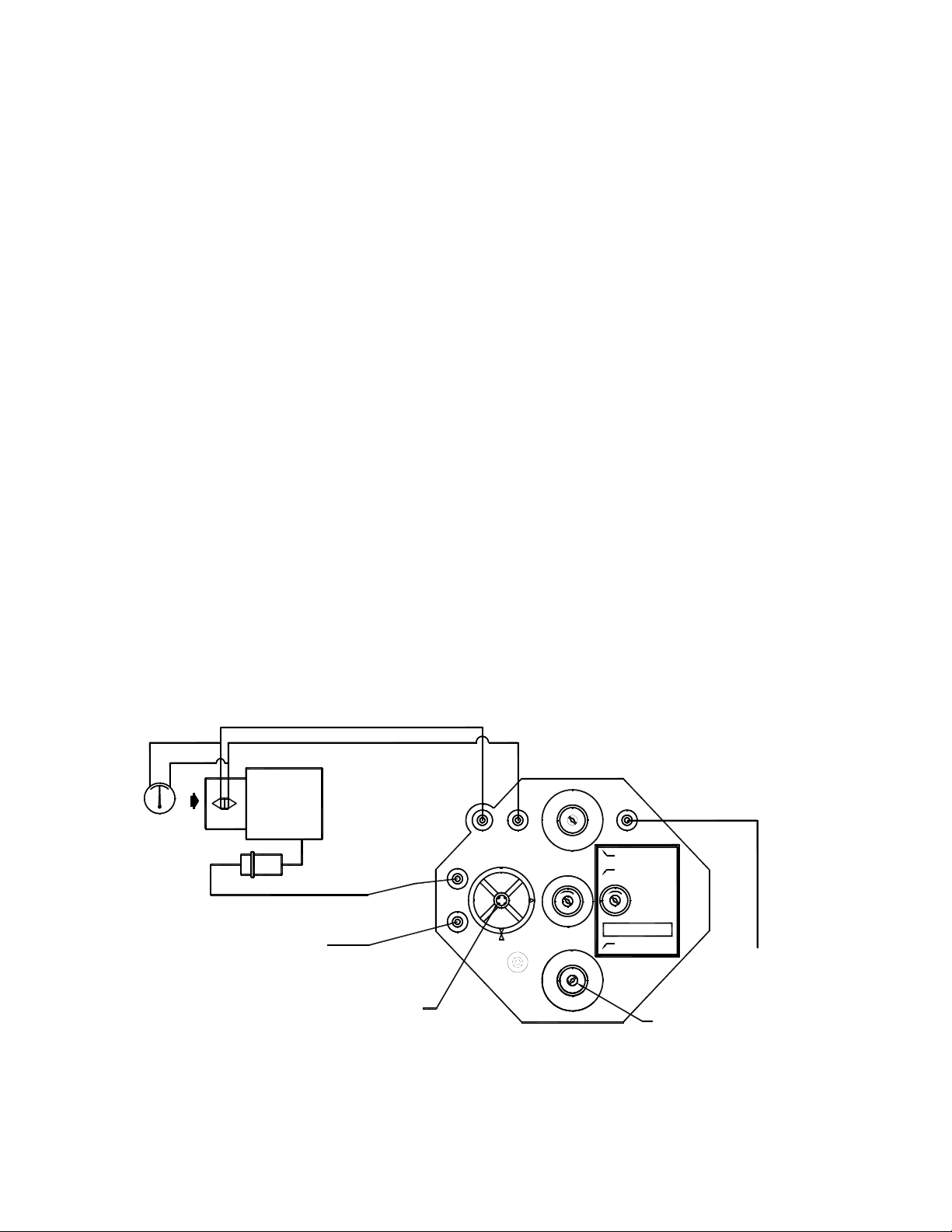
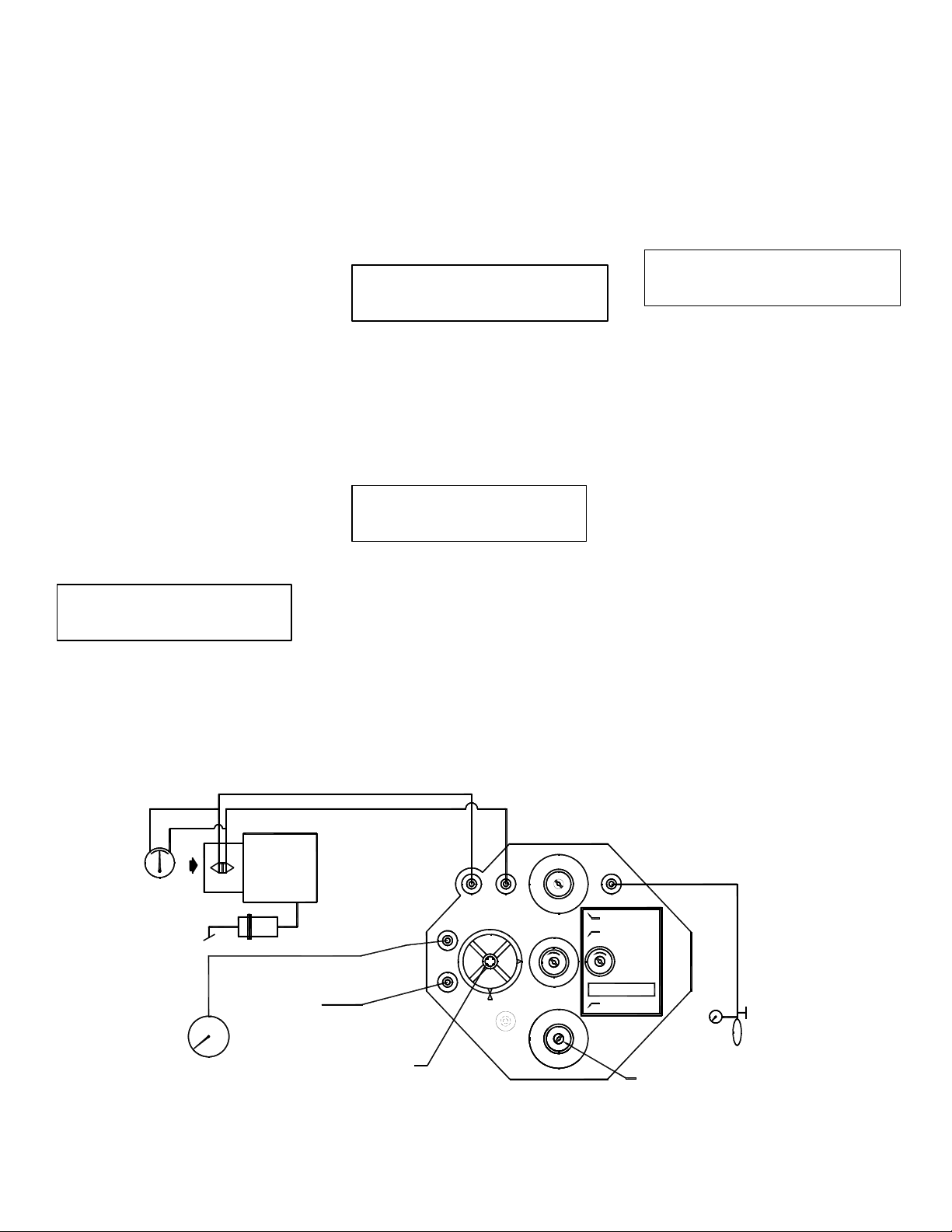
1. Disconnect the actuator tube
(yellow stripe) from controller
Port B.
2. Connect squeeze bulb with 0 to 25
PSI gauge to the actuator.
3. Connect 0 to 25 PSI gauge to
controller Port B (Figure 4).
A. Direct Acting Cooling or Reverse
Acting Heating
1. Apply zero PSI to thermostat
Port T.
2. Read the differential pressure for
the desired Minimum CFM from the
calibration curve corresponding to
the inlet size of the terminal being
calibrated (Page 8).
3. Pump the squeeze bulb until the
desired differential pressure is read
on the manometer gauge.
4. Adjust the LO knob on the face of
the controller until the gauge on
Port B reads 7.5 PSI ± 1.0 PSI.
5. Read the differential pressure for
the desired Maximum CFM from the
calibration curve corresponding to
the inlet size of the terminal being
calibrated (Page 8).
6. Pump the squeeze bulb until the
desired differential pressure is read
on the manometer gauge.
7. Adjust the HI knob on the face of
the controller until the gauge on
Port B reads 7.5 PSI ± 1.0 PSI.
8. Remove gauges and reconnect
actuator to controller Port B.
NOTE: If the actuator fails to respond,
see Guide to Service Procedures.
RED
GR EEN
LOHI
ESV
SENSOR
YELLOW
YELLOW
GAUGE
0-25 PSI
SQUEEZE
BULB
5-10 PSI
ACTUATO R
Figure 4. Controller Setup
B. Reverse Acting Cooling or Direct
Acting Heating
For TITUS I Controllers
1. Apply zero PSI to thermostat
Port T.
2. Read the differential pressure for
the desired Maximum CFM from the
calibration curve corresponding to
the inlet size of the terminal being
calibrated (Page 8).
3. Pump the squeeze bulb until the
desired differential pressure is read
on the manometer gauge.
4. Adjust the HI knob on the face of
the controller until the gauge on
Port B reads 7.5 PSI ± 1.0 PSI.
5. Read the differential pressure for
the desired Minimum CFM from the
calibration curve corresponding to
the inlet size of the terminal being
calibrated (Page 8).
6. Pump the squeeze bulb until the
desired differential pressure is read
on the manometer gauge.
7. Adjust the LO knob on the face of
the controller until the gauge on
Port B reads 7.5 PSI ± 1.0 PSI.
8. Remove gauges and reconnect
actuator to controller Port B.
NOTE: If the actuator fails to respond,
see Guide to Service Procedures.
For TITUS II Controllers
1. Apply 15 to 25 PSI to thermostat
Port T.
2. Read the differential pressure for
the desired Minimum CFM from the
calibration curve corresponding to
the inlet size of the terminal being
WHI TE
LO
BLUE
MAIN AIR
(15-25 PSI)
ROOM THERMOSTAT
(0-15 PSI)
HI
PNEUMATIC
CONTROLLER
B
TM
GAUGE
0-25 PSI
0-2" W.G.
MANOMETER
calibrated (Page 8).
3. Pump the squeeze bulb until the
desired differential pressure is read
on the manometer gauge.
4. Adjust the LO knob on the face of
the controller until the gauge on
Port B reads 7.5 PSI ± 1.0 PSI.
5. Read the differential pressure of the
desired Maximum CFM from the
calibration curve corresponding to
the inlet size of the terminal being
calibrated (Page 8).
6. Pump the squeeze bulb until the
desired differential pressure is read
on the manometer gauge.
7. Adjust the HI knob on the face of
the controller until the gauge on
Port B reads 7.5 PSI ± 1.0 PSI.
8. Remove gauges and reconnect
actuator to controller Port B.
NOTE: If the actuator fails to respond,
see Guide to Service Procedures.
For TITUS IIA Controllers
1. Apply zero PSI to thermostat Port T.
2. Read the differential pressure for
the desired Maximum CFM from the
calibration curve corresponding to
the inlet size of the terminal being
calibrated (Page 8).
3. Pump the squeeze bulb until the
desired differential pressure is read
on the manometer gauge.
4. Adjust the LO knob on the face of
the controller until the gauge on
Port B 7.5 PSI ± 1.0 PSI.
5. Read the differential pressure for
the desired Minimum CFM from the
calibration curve corresponding to
the inlet size of the terminal being
calibrated (Page 8).
6. Pump the squeeze bulb until the
desired differential pressure is read
on the manometer gauge.
7. Adjust the HI knob on the face of
the controller until the gauge on
Port B reads 7.5 PSI ± 1.0 PSI.
8. Remove gauges and reconnect
actuator to controller Port B.
NOTE: If the actuator fails to respond
see Guide to Service Procedures.
Page 3
Calibration Procedure for TITUS I Controller
PNEU-IOM-3.0 5-2-05
A. Direct Acting (Beige). (N.O.)
b. Refer again to the calibration
curve (Page 8) to determine
1. Adjusting minimum air flow:
a. Apply zero PSI signal to Port T
on the controller.
b. If the minimum CFM equals
zero, the damper should
assume a closed
position (observe the indicator
on the end of the damper
the differential pressure
necessary for the required
maximum CFM.
c. Adjust the HI knob on the
controller until the manometer
gauge reads the required
differential pressure from the
curve.
shaft). If not, adjust LO knob on
the controller until the
compressed air drives the
NOTE: If actuator fails to respond,
see Guide to Service Procedure.
damper closed.
c. If a non-zero minimum CFM is
B. Reverse Acting (Gray). (N.C.)
required, read the differential
pressure for the desired CFM
from the calibration curve
corresponding to the inlet size
of the terminal being calibrated
(Page 8).
d. Adjust the LO knob until the
desired differential pressure is
read on the manometer gauge.
Allow several seconds for the
controls to react to system
pressure and stabilize.
1. Adjusting maximum air flow:
a. Apply zero PSI signal to Port T
on the controller.
b. Refer to calibration chart (Page
8). Read the differential
pressure for the desired
maximum CFM from the curve
corresponding to the inlet size
of the terminal being
calibrated.
c. Adjust the HI knob on the
controller until the desired
2. Adjusting maximum air flow:
differential pressure is read on
a. Apply 15-25 PSI signal to
Port T on the controller.
the manometer gauge. Allow
several seconds for the
controls to react to the system
and stabilize.
2. Adjusting minimum air flow:
a. Apply 15-25 PSI signal to
Port T on the controller.
b. If minimum CFM equals zero,
the damper should assume a
closed position (observe
indicator on the end of the
damper shaft). If not, adjust the
LO knob until the damper
closes.
c. If a non-zero minimum CFM is
required, read the differential
pressure for the required CFM
from the curve (Page 8).
d. Adjust the LO knob on the
controller until the manometer
gauge reads the desired
differential pressure from the
curve.
NOTE: If actuator fails to respond,
see Guide to Service Procedures.
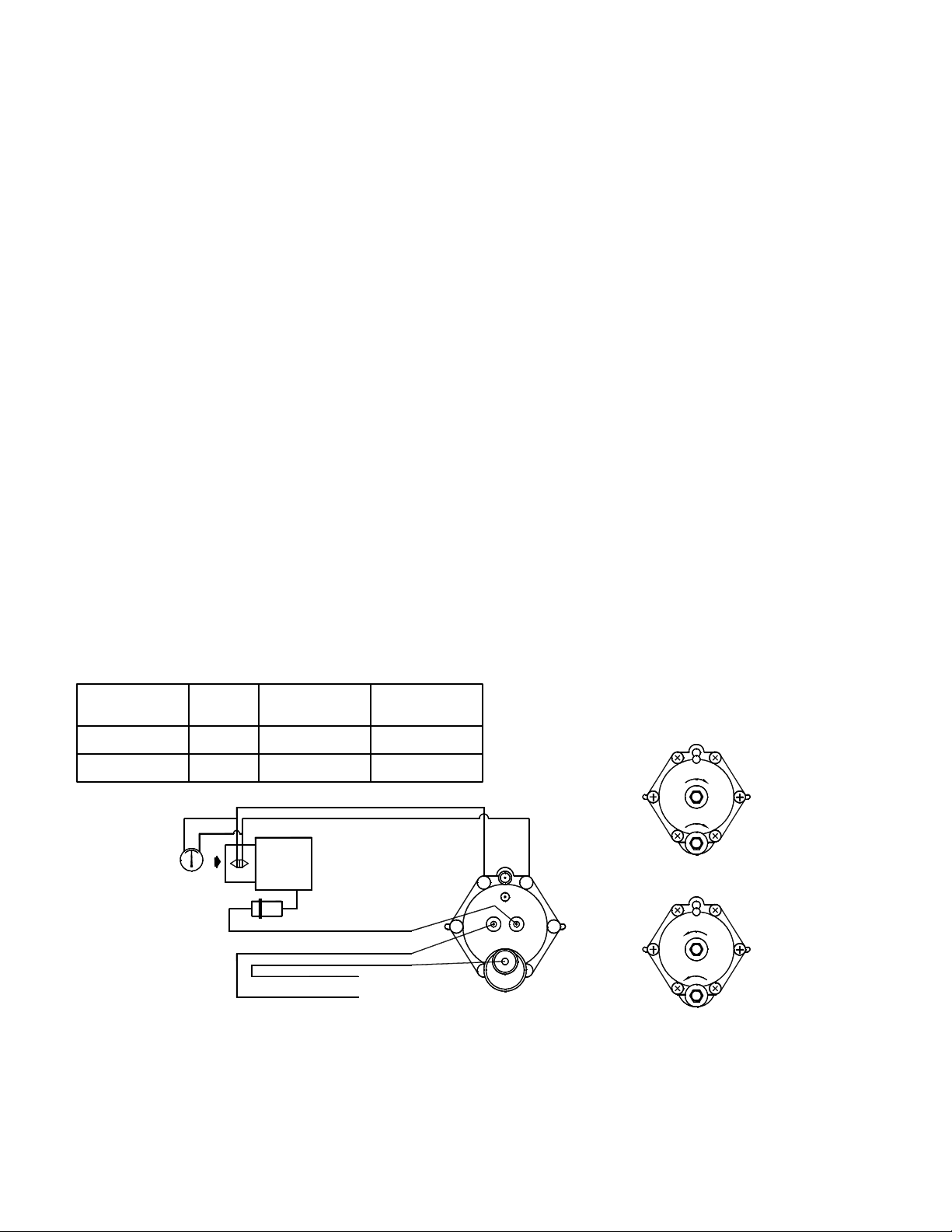
Table 1.
Thermostat
Action
Color Low Port Signal
Direct Beige Y X
Reverse Grey X Y
HI
SENSOR
LO
ACTUATOR
YELLOW
BLUE
WHITE
ROOM THERMOSTAT
(0-15 PSI)
MAIN AIR (20-25 PSI)
H L
MAGNAHELIC
GAUGE
(0-20" WG)
Figure 5. Titus I Controller
High Port
Signal
RED
GREEN
LO
INCREASE
LOLO
HI
INCREASE
HI
M
LO
DIRECT ACTING CONTROLLER
X
Y
B
T
REVERSE ACTING CONTROLLER
HI
BEIGE
HI
INCREASE
LO
LO
INCREASE
HI
GRAY
Page 4
Calibration Procedure for TITUS II Controller
PNEU-IOM-4.0 5-2-05
A. Direct Acting Cooling or Reverse
Acting Heating.
b. Refer again to the calibration
curve (Page 8) to determine
the differential pressure
1. Adjusting minimum air flow:
a. Apply zero PSI signal to Port T
on the controller.
b. If the minimum CFM equals
zero, the damper should drive
to a closed position with
compressed air (observe the
necessary for the required
CFM.
c. Adjust the HI knob on the
controller until the manometer
gauge reads the required
differential pressure from the
curve.
indicator on the end of the
damper shaft). If not, adjust the
LO knob on the controller until
NOTE: If actuator fails to respond,
see Guide to Service Procedures.
the damper is closed.
c. If a non-zero minimum CFM is
required, read the differential
B. Reverse Acting Cooling and
Direct Acting Heating.
pressure for the desired CFM
from the calibration curve
corresponding to the inlet size
of the terminal being calibrated
(Page 8).
d. Adjust the LO knob until the
desired differential pressure is
read on the manometer gauge.
Allow several seconds for the
controls to react to the system
pressure and stabilize.
1. Adjusting minimum air flow:
a. Apply 15-25 PSI signal to
Port T on the controller.
b. If the minimum CFM equals
zero, the damper should
assume a closed position
(observe the indicator on the
end of the damper shaft). If
not, adjust LO knob on the
controller until the damper
closes.
Note: Air flow must be going
across the inlet probe.
c. If a non-zero minimum CFM is
required, read the differential
pressure for the desired CFM
2. Adjusting maximum air flow:
from the calibration curve
a. Apply 15-25 PSI signal to
Port T on the controller.
corresponding to the inlet size
of the terminal being calibrated
(Page 8).
d. Adjust the LO knob until the
desired differential pressure is
read on the manometer gauge.
Allow controls to react to the
system and stabilize.
2. Adjusting maximum air flow:
a. Apply zero signal to Port T on
the controller.
b. Refer again to the calibration
curve (Page 8) to determine the
differential pressure necessary
for the required
maximum CFM.
c. Adjust the HI knob on the
controller until the manometer
gauge reads the required
differential pressure from the
curve.
NOTE: If actuator fails to respond,
see Guide to Service Procedures.
LO
H L
HI
SENSOR
ACTUATOR
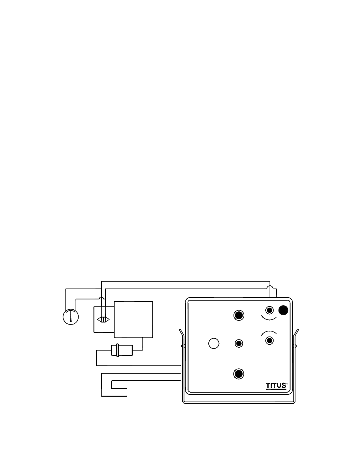
Figure 6. Titus II Controller
YELLOW
WHITE
BLUE
MAIN AIR (20-25 PSI)
ROOM THERMOSTAT
(0-15 PSI)
RED
GREEN
NC
DAMPER
NO
RESET
START
POINT
B
T
M
THERMOSTAT
HOT AIR
RA
DADARA
COLD AIR
CONTROLLER
LO
INCR
HI
Page 5
Reset Start Point Instructions for the TITUS II Controller
PNEU-IOM-5.0 5-2-05
Setup Procedure
3. Use the Squeeze-Bulb to set the
thermostat pressure to 8 PSI or
1. Confirm the setting on the
Thermostat adjustment Switch for
TITUS II controls.
2. Confirm the setting on the Damper
Switch.
(whatever PSI the desired setpoint
should be).
4. Adjust the Reset-Start-Point knob
until the gauge on Port B reads:
(Note 1)
3. Disconnect the red HI and green LO
lines from the controller.
4-5 PSI for normally open terminals
4. Detach the white thermostat line
from Port T on the controller. Attach
a squeeze bulb with 0 to 25 PSI
10-11 PSI for normally closed terminals.
[or]
gauge to Port T.
5. Remove the yellow motor line from
5. SEE NOTE 2.
Port B on the controller. Attach a 0
to 25 PSI gauge to Port B.
To Adjust the Start Point
Reverse-Acting Thermostats:
1. Apply 15 PSI to thermostat Port T.
2. Adjust the LO knob on the face of
Direct-Acting Thermostats:
the controller until the gauge on
Port B reads:
1. Apply zero PSI to thermostat
Port T.
2 PSI for normally closed terminals
2. Adjust the LO knob on the face of
the controller until the gauge on
Port B reads:
15 PSI for normally open terminals.
[or]
3. Use the Squeeze-Bulb to set
thermostat to desired start-point
PSI.
4. Adjust the Reset-Start-Point knob
until the gauge on Port B reads:
(Note 1)
4-5 PSI for normally open terminals
[or]
10-11 PSI for normally closed terminals.
5. SEE NOTE 2.
NOTE 1: Pressures shown are for
5-10 PSI actuators. For other
spring ranges adjust readings
accordingly.
NOTE 2: Reconnect Red-Green-
Yellow-White tubes to their
proper control terminals.
Recalibrate Min./Max. CFM
settings in accordance with
procedures shown in the proper
Installation Manual.
2 PSI for normally closed terminals
[or]
15 PSI for normally open terminals.
LH
0-25 PSI
HI
SENSOR
GAUGE
LO
ACTUATOR
GAUGE
0-25 PSI
YELLOW
WHITE
BLUE
MAIN AIR (20-25 PSI)
RED
GREEN
NC
DAMPER
NO
RESET
START
POINT
B
T
M
THERMOSTAT
HOT AIR
DA
RA
DA
RA
COLD AIR
CONTROLLER
LO
INCR
HI
Figure 7. Titus II Controller
SQUEEZE
BULB
Page 6
Calibration Procedure for TITUS IIA Controller
PNEU-IOM-6.0 5-2-05
A. Direct Acting Cooling or Reverse
Acting Heating.
1. Adjusting minimum air flow:
a. Apply zero PSI signal to Port T
on the controller.
b. If the minimum CFM equals
zero, the damper should
assume a closed position
(observe the indicator on the
end of the damper shaft). If not,
adjust the LO STAT knob on
the controller until the damper
is closed.
c. If a non-zero minimum CFM is
required, read the differential
pressure for the desired CFM
from the calibration curve
corresponding to the inlet size
of the terminal being calibrate
(Page 8).
d. Adjust the LO STAT knob until
the desired differential pressure
is read on the manometer
gauge. Allow several seconds
for the controls to react to the
system pressure and stabilize.
2. Adjusting maximum air flow:
a. Apply 15-25 PSI signal to
Port T on the controller.
b. Refer again to the calibration
curve (Page 8).
c. Adjust the HI STAT knob on
the controller until the
manometer gauge reads the
required differential pressure
from the curve.
2. Adjusting minimum air flow:
a. Apply 15-25 PSI signal to
Port T on the controller.
b. If the minimum CFM equals
zero, the damper should
assume a closed position
(observe indicator on the end
of the damper shaft). If not,
NOTE: If actuator fails to respond,
see Guide to Service Procedures.
adjust the HI STAT knob until
the damper closes.
c. If a non-zero minimum CFM is
B. Reverse Acting Cooling or Direct
Acting Heating
required, read the differential
pressure for the required CFM
from the curve (Page 8).
1. Adjusting maximum air flow:
a. Apply zero PSI signal to Port T
on the controller.
b. Refer to the calibration chart
(Page 8). Read the differential
d. Adjust the HI STAT knob on the
controller until the manometer
gauge reads the desired
differential pressure from the
curve.
pressure for the desired
maximum CFM from the curve
corresponding to the inlet size
NOTE: If actuator fails to respond,
see Guide to Service Procedures.
of the terminal being calibrated.
c. Adjust the LO STAT knob on
the controller until the desired
differential pressure is read on
the manometer gauge. Allow
several seconds for the
controls to react to the system
and stabilize.
LO
H L
MAGNAHELIC
GAUGE
(0-20" WG)
HI
SENSOR
ACTUATOR
MAIN AIR (20-25 PSI)
Figure 8. Titus IIA Controller
RED
GREEN
W
O
L
L
E
Y
E
U
L
B
LOOSEN SCREW TO
CHANGE DAMPER ACTION
(SUPPLIED IN NO POSITION)
H
B
M
DAMPER
NO
WHITE
L
NC
I
R
N
C
G
T
RESET START
LO STAT P
HI STAT P
I
R
N
C
RESET SPAN
ROOM THERMOSTAT
(0-15 PSI)
ALL ADJUSTMENTS CCW TO INCREASE
WITH 5/64" HEX ALLEN WRENCH
(FIELD ADJUSTERS HAVE KNOBS)
Page 7
Reset Start Point Instructions for the TITUS IIA Controller
PNEU-IOM-7.0 5-2-05
Setup Procedure
3. Use the Squeeze-Bulb to set the
thermostat pressure to 8 PSI or
1. Confirm the setting on the
Thermostat adjustment Switch for
TITUS IIA controls.
2. Confirm the setting on the Damper
Switch.
(whatever PSI the desired setpoint
should be).
4. Adjust the Reset-Start-Point knob
until the gauge on Port B reads:
(Note 1)
3. Disconnect the red HI and green LO
lines from the controller.
4. Detach the white thermostat line
from Port T on the controller. Attach
4-5 PSI for normally open terminals
[or]
10-11 PSI for normally closed terminals.
a squeeze bulb with 0 to 25 PSI
gauge to Port T.
5. SEE NOTE 2
5. Remove the yellow motor line from
Port B on the controller. Attach a 0
Reverse-Acting Thermostats:
to 25 PSI gauge to Port B.
1. Apply 15 PSI to thermostat Port T.
To Adjust the Start Point
2. Adjust the LO knob on the face of
the controller until the gauge on
Direct-Acting Thermostats:
1. Apply zero PSI to thermostat
Port T.
2. Adjust the LO knob on the face of
Port B reads:
2 PSI for normally closed terminals
[or]
15 PSI for normally open terminals.
the controller until the gauge on
Port B reads:
3. Use the Squeeze-Bulb to set
thermostat to desired start-point
PSI.
4. Adjust the Reset-Start-Point knob
until the gauge on Port B reads:
(Note 1)
10-11PSI for normally open terminals
[or]
4-5 PSI for normally closed terminals.
5. SEE NOTE 2.
NOTE 1: Pressures shown are for
5-10 PSI actuators. For other
spring ranges adjust readings
accordingly.
NOTE 2: Reconnect Red-Green-
Yellow-White tubes to their
proper control terminals.
Recalibrate Min./Max CFM
settings in accordance with
procedures shown in the proper
Installation Manual.
2 PSI for normally closed terminals
[or]
15 PSI for normally open terminals.
H L
MAGNAHELIC
GAUGE
(0-20" WG)
HI LO
SENSOR
ACTUATOR
MAIN AIR (20-25 PSI)
GAUGE
(0-25 PSI)
Figure 9. Titus II Controller
RED
GREEN
W
O
L
L
E
Y
E
U
L
B
LOOSEN SCREW TO
CHANGE DAMPER ACTION
(SUPPLIED IN NO POSITION)
H
B
M
DAMPER
NO
WHITE
R
T
RESET START
LO STAT P
HI STAT P
I
R
N
C
RESET SPAN
Gauge
(0-25 PSI)
ALL ADJUSTMENTS CCW TO INCREASE
WITH 5/64" HEX ALLEN WRENCH
(FIELD ADJUSTERS HAVE KNOBS)
Squeeze
Bulb
L
NC
I
N
C
G
Page 8
AeroCross
TM
Multi-Point Inlet Sensor
PNEU-IOM-8.0 5-2-05
INLET DIAMETER (INCHES )
1.0
0.7
0.5
0.4
0.3
0.2
0.1
0.07
0.05
INLET SENSOR DIFFERENTIAL (IN. W.G.)
0.04
0.03
504070
100
200
300
5"4"
400
CFM
6"
500
Figure 10. AeroCrossTM Sensor Calibration Curves
700
9"8"7"
1000
8"X14"
10"
12"
2000
8"X18"
16"14" 16"x24"
3000
4000
5000
7000
10000
Table 2. AeroCrossTM K-Factors
Terminal
Size
04
05
06
07
08
09
10
12
14
16
8x14
8x18
40(16x24)
K-Factor
(CFM)
273
390
448
667
904
1167
1436
1891
3015
3839
2106
2498
7176
CFM = K P
2
CFM
P =
( )
K
Original Titus Multi-Point Inlet Sensor (for use with units shipped before April 1, 2002)
12" OR 8"X14"
INLET DIAMETER (INCHES)
5"
1.0
.7
.5
.4
.3
.2
0.1
.07
.05
.04
INLET SENSOR DIFFERENTIAL (IN W.G.)
.03
70
50
40
100
4"
200
6"
7"
8"
10"
9"
500
400
300
700
1000
16"
14"
3000
2000
4000
CFM
5000
18" OVAL
16"X24"
7000
10000
Table 3. Original Sensor K-Factors
Terminal
Size
04
05
06
07
08
09
10
12
14
16
40(16x24)
CFM = K P
CFM
P =
( )
K
K-Factor
(CFM)
269
404
474
625
881
1094
1371
1931
2795
3677
7784
2
Figure 11. Original Sensor Calibration Curves
Page 9

Guide to Service Procedures
PNEU-IOM-9.0 5-2-05
Actuator will not stroke. (Generally any setting of
the damper compatibility selector on the face of
the controller).
Actuator will not stroke. (Normally open setting
of the damper compatibility selector on the face
of the controller.)
Actuator will not stroke. (Normally closed setting
of the damper compatibility selector on the face
of the controller).
Actuator remains fully stroked at all times.
(Normally open setting of the damper
compatibility selector on the face of the
controller).
Actuator remains fully stroked at all times.
(Normally closed setting of the damper
compatibility selector on the face of the
controller).
Inaccurate or erratic air flow control. 1. Check inlet duct for blockage or kinks.
1. Leak in the control line between the controller
and the actuator.
2. Leak in the actuator.
3. Insufficient main air supply pressure.
4. Faulty controller.
5. Pneumatic thermostat and main air line
connections are reversed at the controller.
6. Control lines from the sensor to the controller
are reversed.
1-6 as above.
7. Rubber caps on HI or both balancing tees are
missing.
8. HI control line or the HI passage of the sensor
is plugged.
9. Damper compatibility selector on the face of
the controller is set wrong.
10. Low differential pressure at the sensor.
1-6 as above.
7. Rubber cap on the LO balancing tee is
missing.
8. LO control line or the LO passage in the
sensor is plugged.
1. Faulty controller.
2. Rubber cap on the LO balancing tee is
missing.
3. LO control line or the LO passage of the
sensor is plugged.
1. Faulty controller.
2. Control lines from the sensor to the controller
are reversed.
3. Rubber caps on HI or both balancing tees are
missing.
4. HI control line or the HI passage of the sensor
is plugged.
5. Damper compatibility selector on the face of
the controller is set wrong.
6. Low differential pressure at the sensor.
1. Poor inlet duct connection.
2. Leakage in the duct work.
3. Assembly mounted in a non-level position or
upside down.
4. Controller adjustment dials are not set
correctly.
5. Low velocity pressure in the inlet duct.
6. Thermostat compatibility selector on the face
of the controller is set wrong.
7. Thermostat is out of calibration.
1. Repair the leak.
2. Apply 15-25 PSI air from the main air supply
to the actuator. The actuator should stroke.
Pinch the air supply line. If the actuator retracts,
it is leaking. Replace the actuator and contact
your TITUS distributor.
3. The controller must receive compressed air
from the main supply at 15-25 PSI. Be sure all
connections are as shown in Figure 9.
4. If the controller appears to be faulty, contact
your Titus distributor.
5. See Figure 9. The Thermostat must be
connected to Port T and the main air to Port M.
6. See Figure 9. Make the connections as
shown.
1-6 as above.
7. Replace the caps on the balancing tees.
8. Clean out the passage or control line
9. Set the damper compatibility selector to
match the action of the damper.
10. Increase the air flow rate to the terminal inlet
if necessary.
1-6. As above.
7. Replace the cap
8. Clean out the passage or control line.
1. If the controller appears to be faulty, contact
your Titus products distributor.
2. Replace the cap.
3. Clean out the passage or control line.
1. If the controller appears to be faulty, contact
your Titus products distributor.
2. See Figure 9. Make the connections as
shown.
3. Replace the caps on the balancing tees.
4. Clean out the passage or control line.
5. Set the damper compatibility selector to
match the action of the damper.
6. Increase the air flow rate to the terminal inlet
if necessary.
2. Repair the leakage.
3. Control must be horizontal ± 10 degrees.
4. See “Adjusting the Minimum and Maximum
Air flow”.
5. Increase the air flow rate to the terminal inlet
if necessary.
6. Set the thermostat compatibility selector to
match the action of the thermostat.
7. Turn the thermostat adjusting dial through its
full travel. The air pressure signal delivered by
the thermostat to Port T on the back of the
controller must vary from 0 to main air supply
pressure (15-25 PSI). If this pressure range is
not correct, recalibrate the thermostat or consult
your Titus products distributor.
Page 10

Replacement Parts
Actuators
Krueter MCP-8031 (5-10PSI) 10058501
Johnson D-3062 (5-10PSI) 10058601
Actuator Crank Arms
Krueter 30192002
Johnson 30192006
Actuator Mounting Plate-RH/LH 70560301
Controllers
Titus I DA (Beige) 10015001
Titus I RA (Gray) 10015101
Titus II 70500001
Titus IIA 10065001
Room Thermostats
Std. DA one pipe 10182203
Std. RA one pipe 10182204
Std. DA two pipe 10182201
Std. RA two pipe 10182202
Restrictor Tee (.005) 41410174
Restrictor Inline (.0063) 41410164
PNEU-IOM-10.0 5-2-05
Pneumatic Controller Mounting Bracket
Titus I 70267002
Titus II, IIA, III 70382901
Controller Box
Enclosure (Titus II, IIA, III) 70073401
Cover (Titus II, IIA, III) 70073501
Enclosure Titus I 70267201
Cover Titus I 70267101
AeroCrossTM Flow Sensor
4", 5" 3151520001
6" 3151520002
7" 3151520003
8" 3151520004
9" 3151520005
10" 3151520006
12" 3151520007
14" 3151520008
16" 3151520009
 Loading...