

Page 1
VERTICAL HIGH OUTPUT VHC-IOM-00 01-19-09
INSTALLATION AND
MAINTENANCE INSTRUCTIONS
VHC
INSTALLER MUST BE A TRAINED, EXPERIENCED SERVICE
TECHNICIAN
1. PRESSURE CHECK
When the valve package is factory installed, the unit is shipped with the coil and
associated piping/valve package pressurized. Use the air valve to release the pressure.
Should there be no pressure, inspect the unit for possible shipping damage. The unit
must be pressure tested again prior to installation.
2.
This unit is free standing. It MUST be leveled when installed. When leveling legs
3.
3.1 All piping leading to the unit must be adequately supported to prevent excessive stress
3.2 Threaded connections must not be over tightened.
3.3 Sweat connections must not be overheated. Use solder (95/5) with a melting
3.4 When the valve package is supplied separately for field installation, carefully follow
MOUNTING
are supplied (optional), these are located under the unit’s bottom panel. Turn the bolts
as required until the unit is perfectly leveled to ensure proper condensate drainage.
PIPING
on the unit’s piping. However, sufficient free movement is required for thermal
expansion/contraction.
o
temperature below 600
the schematic piping diagram and installation instructions provided with the package.
F.
3.5 The inlet (supply), outlet (return) and condensate (drain) points are clearly marked on
the unit’s piping. Depending upon the filed piping layout, the connecting inlet, outlet
and condensate piping could be at the right or left side of the unit. Follow the
Engineer’s pipe layout drawing while routing the supply, return and drain lines to and
from the unit.
3.6 All pipes and fittings outside the unit’s enclosure must be properly insulated as no
external condensate pan is provided with the standard unit.
5 fo 1 egaP
Page 2
VERTICAL HIGH OUTPUT VHC-IOM-00 01-19-09
INSTALLATION AND
MAINTENANCE INSTRUCTIONS
4. ELECTRICAL
4.1 All electrical connections are to be made in accordance with the National Electric
Code, state and local codes, bylaws, ordinances or the authority having jurisdiction.
Make all electrical connections inside the internal electric junction box by carefully
following the wiring diagram.
4.2 Electrical wiring diagram is located inside the unit’s enclosure. Adhere strictly to it in
order to avoid damage and/or personal injury.
4.3 When the thermostat and fan switch are field supplied, the following are the minimum
electrical ratings:
- Thermostat (valve load) = 0.1A @ 115V
(0.05A @ 230V)
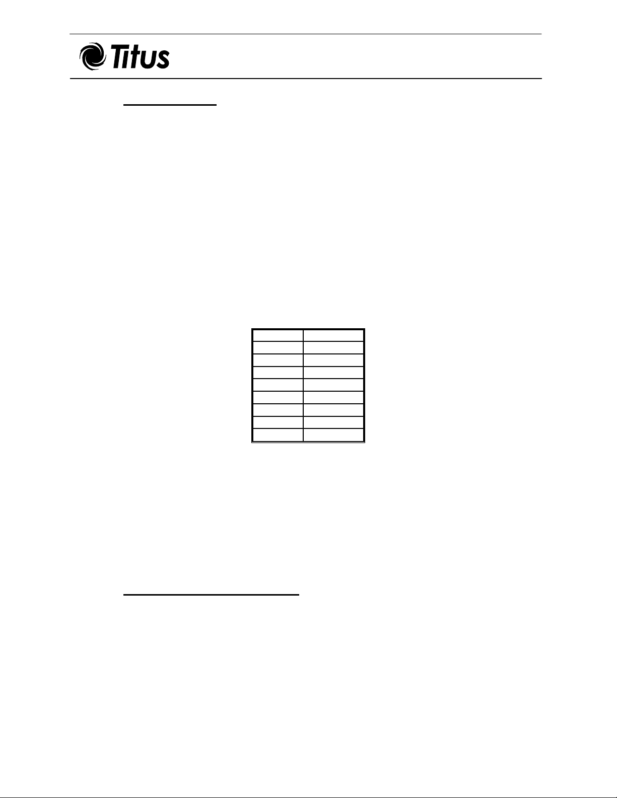
- Fan Motor(s) @ full load amps, FLA (@115V):
SIZE FLA (Amps)
06 3.5
08 3.5
10 3.7
12 4.0
14* 3.5
16* 3.5
18* 3.5
20* 4.0
*Note: Units are equipped with two (2) motors; full load amperage listed is per motor.
4.4 Where electric heating is provided with the unit (optional), an external HEAT/COOL
changeover switch has to be installed – normally wall mounted together with the fan
speed selector switch. At minimum, this switch should be rated: 10A @ 115V (5A @
230V).
4.5 Follow the wiring diagram for correct installation.
5.
GENERAL PRECAUTIONS
After completing the installation, recheck the following:
5.1 The drain pans, fans and motors are clean of all foreign material.
5.2 All electric wiring is properly routed, secure and capped.
5.3 The filter is clean and secured in its position.
5 fo 2 egaP
Page 3

VERTICAL HIGH OUTPUT VHC-IOM-00 01-19-09
INSTALLATION AND
MAINTENANCE INSTRUCTIONS
6. INITIAL START-UP
6.1 Chilled/Hot Water Unit
6.1.1 Ensure that the main distribution system is operable (i.e. both supply and return piping
are under full operating pressure).
6.1.2 Open the unit’s isolating ball valves (optional) and observe that no leaks are evident.
6.1.3 Open the 2-Way or 3-Way Valve (optional) manually by turning the manual override
to the open position on the valve actuator thus pressurizing the unit’s coil.
6.1.4 Remove the cap of the air-vent valve and depress the needle to release the trapped air.
Continue until only liquid is coming through and then re-cap and secure tightly.
7.
OPERATION AND CONTROL
7.1 The unit is wired to operate with a four-position fan selector switch (optional):
OFF
HI High fan speed
MED Medium fan speed
LO Low fan speed
7.2 An external thermostat (normally wall mounted) is used to select the desired room
temperature.
7.3 Where the unit is provided with electric heating (optional), the external HEAT/COOL
changeover switch has to be set in the HEAT position to enable the thermostat to
switch the heater ON when the room temperature drops below the set point.
8.
MAINTENANCE
***CAUTION: All maintenance must be performed by a trained, experienced
service technician. To prevent electrical shock, disconnect electric power to system
at main fuse or circuit breaker box until maintenance is complete.
At the completion of any maintenance check for foreign materials and replace the
front panel and/or the safety mesh behind the filter. Switch on the power at the
supplied electrical source (circuit breaker).
5 fo 3 egaP
Page 4

VERTICAL HIGH OUTPUT VHC-IOM-00 01-19-09
INSTALLATION AND
MAINTENANCE INSTRUCTIONS
8.1 Filter Replacement
8.1.1 The useful life of the throwaway filter provided with the unit depends on the
environment in which the unit is operating. However, it is recommended to change the
filter at least every three (3) months.
8.1.2 No tools are required to remove the filter. Pull it up and out from its guides.
8.2 Drain Pan
8.2.1 Periodic inspection of the drain pan for restriction of drainage is important. The
frequency of inspection becomes shorter in high humidity regions.
8.3 Coil
8.3.1 A clogged (dusty, lint covered, dirty, etc.) coil is a major cause of unit inefficiency and
failure. Periodic inspection should take place at least once a year.
8.3.2 Cleaning of the coil should be done with an appropriate coil cleaning brush and a
vacuum cleaner, or compressed air. Care should be taken not to damage or bend the
coil fins.
8.4 Electric Motor
8.4.1 Motor inspection and lubrication should take place annually. To remove the
blower/motor assembly, unscrew the holding screws located behind the flange and
slide the assembly out.
8.4.2 Clean all dirt and lint with a brush and/or vacuum cleaner.
8.5 Strainer (Optional)
8.5.1 The frequency that the strainer has to be cleaned depends on the overall conditions of
the distribution piping system. However, frequent cleaning is recommended during the
installation and start-up stages and thereafter at every season change
(Summer/Winter).
8.5.2 Open the clean-out cap on the strainer to release the dirt. Close it once clear liquid is
observed.
8.6 Pete’s Plug (Optional)
8.6.1 The plug is installed as an aid in measuring pressure and temperature.
5 fo 4 egaP
Page 5

VERTICAL HIGH OUTPUT VHC-IOM-00 01-19-09
INSTALLATION AND
MAINTENANCE INSTRUCTIONS
8.7 Electric Heater(s) (Optional)
8.7.1 The heater is fastened to the discharge collar at the blower outlet with sheet metal
screws.
8.7.2 In case of heater failure, follow the procedure described below:
8.7.3 Disconnect all power sources before attempting to open the unit. Check all electrical
wiring to ensure the unit is fully isolated.
8.7.4 Unscrew the front access panel and expose the heater(s).
8.7.5 If the thermal cut-out switch is defective, disconnect the electrical wires and unscrew
it from the heater assembly. Obtain a replacement from TITUS and
reinstall.
8.7.6 If the heating element (the spiral resistance wire) is burned out, unscrew the heater
assembly from the fan deck, disconnect the terminals and replace with a new heater
obtained from TITUS.
***When contacting TITUS for replacement parts, always
refer to the complete Model, Order and Line numbers on the Serial
Plate located on the blower housing.
605 Shiloh Road
Plano, Texas 75074
972-212- 4800
5 fo 5 egaP
 Loading...