

Page 1
VERTICAL STACK VS-IOM-00 01-19-09
INSTALLATION AND
MAINTENANCE INSTRUCTIONS
VSR, VSRM, VSRS, VSM/VSS
INSTALLER MUST BE A TRAINED, EXPERIENCED TECHNICIAN
1. INSTALLATION
1.1 BEFORE DRYWALL INSTALLATION:
1.1.1 Position unit to align risers with holes in floor. Lower into position. Should the units be
supplied with extensions, weld them to the top of the risers. Extensions for unit on
floor 1 is to be welded to the bottom of risers of the unit on floor 2. Follow this procedure
all the way up in each line.
1.1.2 Level the unit to ensure proper condensate drainage.
1.1.3 If necessary, anchor the unit to the floor through the bottom panel.
1.1.4 Pressure test the complete system.
1.1.5 Make all electrical connections (except for thermostats) inside the internal electric
junction box in accordance with the wiring diagram located on the blower housing. All
electrical work must be made in accordance with The National Electric Code, state and
local codes, bylaws, ordinances or the authority having jurisdiction.
1.2 APPLY DRYWALL to unit as required. Care must be taken not to penetrate any part of
the electrical or drain systems with the drywall screws. Do not allow drywall dust to enter
the unit. This can damage components, such as the motor, shorten component life and
reduce unit efficiency.
6 fo 1 egaP
Page 2
VERTICAL STACK VS-IOM-00 01-19-09
INSTALLATION AND
MAINTENANCE INSTRUCTIONS
2. ELECTRICAL
2.1 All electrical connections are to be made in accordance with the National Electric
Code, state and local codes, bylaws, ordinances or the authority having jurisdiction.
Make all electrical connections inside the electric junction box by carefully
following the wiring diagram.
2.2 Adhere strictly to the electrical wiring diagram in order to avoid damage and/or
personal injury.
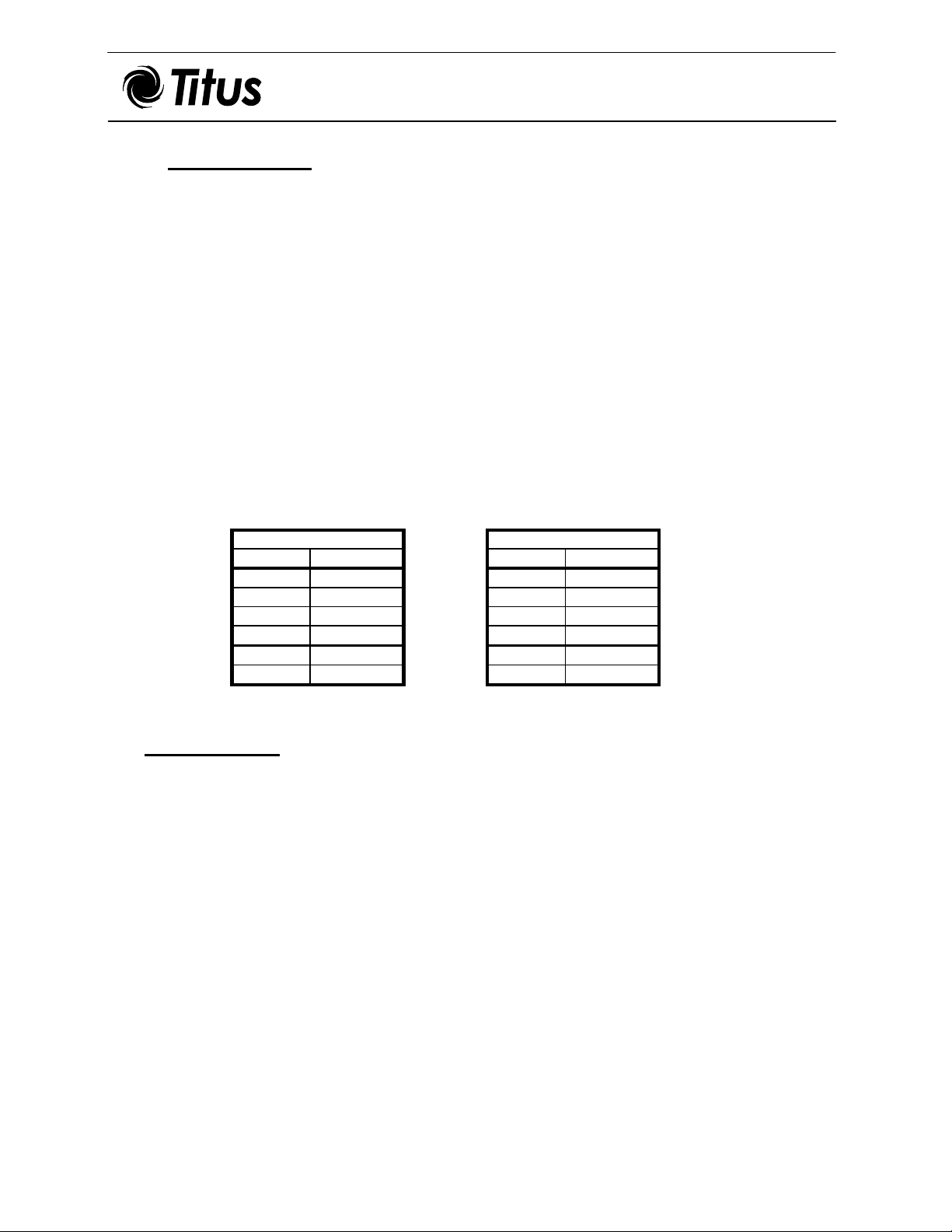
2.3 When the thermostat and fan switch are field supplied, the following are the minimum
electrical ratings:
- Thermostat (valve load) = 0.1A @ 115V
(0.05A @ 230V)
- Fan Motor(s) @ full load amps, FLA (@115V):
INSPECTION
3.
STANDARD MOTOR
SIZE FLA (Amps)
03 1.3
04 1.4
06 2.0
08 2.9
10 4.0
12 3.7
HIGH STATIC MOTOR
SIZE FLA (Amps)
03 1.6
04 1.6
06 2.9
08 3.5
10 4.3
12 4.0
3.1 Check that the electrical power to the unit is OFF.
3.2 Check that the disconnect switch mounted on the internal electric box is OFF.
3.3 Check drain pan for foreign materials.
3.4 Check fan and motor for foreign materials and freedom of movement.
3.5 Check that all wiring is properly terminated and the internal electric junction box is
properly covered.
3.6 Check that the filter is clean and secured in position.
6 fo 2 egaP
Page 3

VERTICAL STACK VS-IOM-00 01-19-09
INSTALLATION AND
MAINTENANCE INSTRUCTIONS
4. AFTER DRYWALL INSTALLATION
4.1 Install Supply Grille using screws provided.
4.2 Install the Access Panel. The panel hangs on the channel at the top of the front opening in
the unit. The 1/4-turn fasteners (optional) are to be adjusted to accommodate drywall
thickness.
Adjustment can be made by loosening the set-screw on the fastener shaft and adjust as
required. The top hanging channel is adjusted by loosening the three (3) screws facing up
in the channel and slide the channel in or out as required.
4.3 Install thermostat on unit per wiring diagram. Install insulation provided into junction
box behind thermostat.
5.
INITIAL START UP
5.1 Ensure that the main water distribution (both supply and return) piping are operable and
under full operating pressure.
5.2 Open the unit’s two (2) isolating ball valves (optional) and carefully check that no leaks
are present.
5.3 Turn on the supplied electrical power (circuit breaker).
5.4 Turn the disconnect switch located on the internal electrical box to the ON position.
5.5 On the thermostat, set the temperature and turn on the fan switch. At this time the fan
should be running and the zone valve should be open.
5.6 Bleed the air from the coil by removing the cap of the air vent valve and depressing the
needle valve until liquid comes out. Recap the valve and secure the cap tightly.
5.7 Inspect the coil and all plumbing for leaks.
Fresh Air Damper (Optional)
6.
The Fresh Air Damper is located near the bottom of the unit below the drain pan. Slide
the adjustable door in its tracks to the proper position giving the required amount of fresh
air. Secure in place with a sheet metal screw.
6 fo 3 egaP
Page 4

VERTICAL STACK VS-IOM-00 01-19-09
INSTALLATION AND
MAINTENANCE INSTRUCTIONS
7. OPERATION AND CONTROL
7.1 The unit is wired to operate with a four-position fan selector switch:
OFF
HI High fan speed
MED Medium fan speed
LO Low fan speed
7.2 An external thermostat (normally wall mounted) is used to select the desired room
temperature.
7.3 Where the unit is provided with electric heating (optional), the external HEAT/COOL
changeover switch has to be set in the HEAT position to enable the thermostat to
switch the heater ON when the room temperature drops below the set point.
8.
MAINTENANCE
***CAUTION: All maintenance must be performed by a trained, experienced service
technician. To prevent electrical shock, disconnect electric power to system at main fuse
or circuit breaker box until maintenance is complete.
8.1 If you are working on any internal part of the unit other than filter replacement or drain
pan inspection, you must also switch OFF the power at the supplied electrical source
(circuit breaker).
8.2 Remove the front access panel by removing (2) fastening screws or turning the two (2)
1/4-turn fasteners (optional) at the bottom of the panel and lifting it up off the top
channel. Switch OFF the power with the disconnect switch mounted on the internal
electrical box.
8.3 At the completion of any maintenance check for foreign materials, switch ON the power
at the disconnect switch mounted on the internal electrical box and replace the front
access panel by hanging it on the upper channel and turning the two (2) fastening screws
or (2) 1/4 turn fasteners (optional). Switch on the power at the supplied electrical source
(circuit breaker).
8.4
Filter Replacement
The useful life of the throwaway filter provided with the unit depends on the environment
in which the unit is operating. However, it is recommended to change the filter at least
every three (3) months.
6 fo 4 egaP
Page 5

VERTICAL STACK VS-IOM-00 01-19-09
INSTALLATION AND
MAINTENANCE INSTRUCTIONS
8.4.1 Switch the power OFF at the disconnect switch.
8.4.2. Release the two (2) spring fasteners holding the filter in place and
remove the filter.
8.4.3. Insert a new filter of the same size and close the two (2) spring
fasteners.
8.4.4. Switch the power ON at the disconnect switch.
8.5
Periodic inspection of the drain pan for restriction of drainage is important. The
8.6
A clogged (dusty, lint covered, dirty, etc.) coil is a major cause of unit inefficiency and
8.6.1 Cleaning of the coil should be done with an appropriate coil cleaning brush and a vacuum
8.7
8.7.1 Clean all dirt and lint with a brush and/or vacuum cleaner.
Drain Pan
frequency of inspection becomes shorter in high humidity regions. In order to access the
pan, remove the metal spring clip from the P-trap and drain pan copper stub and pull
forward.
Coil
failure. Periodic inspection should take place at least once a year.
cleaner, or compressed air. Care should be taken not to damage or bend the coil fins.
Electric Motor
Motor inspection should take place annually. To remove the blower/motor assembly,
unscrew the nuts located in front of the deck assembly and snap the assembly out.
6 fo 5 egaP
Page 6

VERTICAL STACK VS-IOM-00 01-19-09
INSTALLATION AND
MAINTENANCE INSTRUCTIONS
8.8 Strainer (Optional)
The frequency that the strainer has to be cleaned depends on the overall conditions of the
distribution piping system. However, frequent cleaning is recommended during the
installation and start-up stages and thereafter at every season change (Summer/Winter).
8.8.1 Open the clean-out cap on the strainer to release the dirt. Close it once clear liquid is
observed.
8.9 Pete’s Plug (Optional)
The plug is installed as an aid in measuring pressure and temperature.
8.10
The heater is fastened to the fan deck at the blower outlet with sheet metal screws.
In case of heater failure, follow the procedure described below:
8.10.1 Disconnect all power sources before attempting to open the unit. Check all electrical
8.10.2 Unscrew the fan deck and expose the heater.
8.10.3 If the thermal cut-out switch is defective, disconnect the electrical wires and unscrew
8.10.4 If the heating element (the spiral resistance wire) is burned out, unscrew the heater
Electric Heater(s) (Optional)
wiring to ensure the unit is fully isolated.
it from the heater assembly. Obtain a replacement from TITUS and reinstall.
assembly from the fan deck, disconnect the terminals and replace with a new heater
obtained from TITUS.
***When contacting TITUS for replacement parts, always refer to the
complete Model, Order and Line numbers on the Serial Plate located on
the blower housing.
605 Shiloh Road
Plano, Texas 75074
972-212-4800
6 fo 6 egaP
 Loading...