

Page 1
Installation Manual
IOM-VAB-00 06-30-04
VAB Vertical Air Handler Belt Drive
Installation, Operation, and Maintenance Manual
Contents Page
General ....................................................................1
Introduction.............................................................1
Safety .......................................................................1
Inspection................................................................1
Product Description ............................................... 1
Model Number Specification .............................................1
Dimension Specification .................................................... 1
Unit Cabinet Dimensions...................................................2
Coil Specifications ............................................................. 2
Dimensional Drawings.......................................................2
Installation...............................................................4
Ductwork ...........................................................................4
Duct Insulation and Vapor Proofing................................... 4
Motors and Drives .............................................................4
Sound Attenuation............................................................. 4
Electrical Connections....................................................... 4
Condensate Drain .............................................................5
Water Piping......................................................................5
Installation of Options............................................5
Discharge / Return Air Plenum..........................................5
Electric Heater................................................................... 6
Startup ..................................................................... 6
Operation and Maintenance ..................................7
Return Air Filters ...............................................................7
Coil .................................................................................... 7
Belt and Pulley ..................................................................7
Motor ................................................................................. 7
Blower ...............................................................................7
Abbreviations.......................................................... 7
General
This document provides installation, operation, and
maintenance information for the Titus Vertical Air Handler
Belt Drive (VAB) models.
Additional information may be found at the Titus website,
www.titus-hvac.com.
Introduction
The following information is to be used by the installer as a
guide. Since each installation is unique unto itself, only
general topics are covered. The order in which topics are
presented may not be those required by the actual
installation.
This guide does NOT supersede or circumvent any
applicable national, state, or local codes.
The installation is to be performed only by individuals
whose experience meets or exceeds the requirements of
the work involved.
The installer must read the entire contents of
and develop a thorough understanding before beginning
installation.
Due to a continuing program of product research, Titus
reserves the right to discontinue or change without notice,
any or all specifications or designs without incurring
obligations.
this guide
Safety
The installation and/or servicing of comfort conditioning
equipment can be hazardous due to system pressures
and electrical devices.
Caution: Only trained and qualified personnel
should perform service and/or installation.
Observe all precautions and warnings in product
data or attached to the unit.
Follow all safety codes. Wear eye protection and gloves.
Have a fire extinguisher readily avai
Caution: Disconnect all power supplies before
accessing equipment.
Disconnecting more than one power supply may
be required to de-energize some equipment.
DANGER
ELECTRIC SHOCK CAN CAUSE DEATH.
lable.
Inspection
Thoroughly inspect all packages upon receipt. Ensure
carton(s) have not been dropped, crushed or punctured.
Inspect all contents for damage. If damage is found,
immediately file a claim with the delivering carrier.
Product Description
This section provides model number nomenclature,
various unit dimensions, and coil specification.
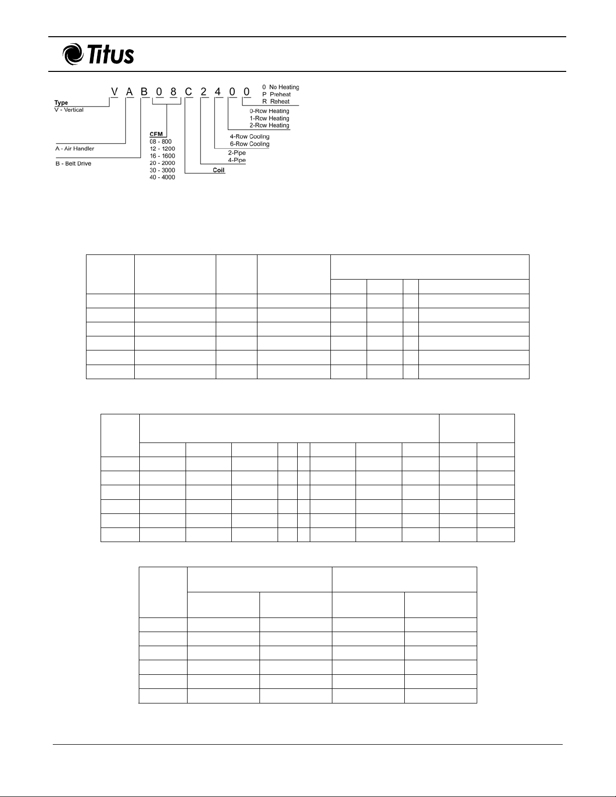
Model Number Specification
Figure 1 defines model number nomenclature specifics.
Dimension Specification
Table 1 provides VAB model dimension specifics such as
tonnage, blower, filter dimensions, optional discharge or
return air plenum, and shipping weight of plenum.
605 Shiloh Road • Plano, Texas 75074 • 972- 212-4800
All rights reserved. No part of this work may be reproduced or transmitted in any form or any means, electronic or mechanical, including photocopying and recording, or by any information storage retrieval system without permission in writing from Air Distribution Technologies.
Page 2
VAB Installation Manual
IOM-VAB-00 06-30-04
Unit Cabinet Dimensions
Table 2 provides the cabinet dimensions for each VAB
model along with the blower-opening outlet.
Coil Specifications
Table 3 provides VAB model specifics for the chilled and hot
water coil outside diameter and shipping weight based on
the number of coils (weight for 4-row chilled water coil
includes weight for entire unit).
Figure 1. Air Handler Model Number
Nomenclature
Table 1. VAB Model Dimensions
Model
VAB08 2 9 x 9 20 x 20 22 23-1/2 12 23
VAB12 3 9 x 9 20 x 20 22 23-1/2 12 23
VAB16 4 10 x 10 22-1/2 x 22-1/2 25 23-1/2 14 30
VAB20 5 12 x 12 (2) 16 x 25 29-1/4 25-1/2 16 35
VAB30 7-1/2 15 x 15 (3) 16 x 25 39 27 24 41
VAB40 10 15 x 15 (4) 20 x 25 51-1/2 27 24 41
Nominal Rating in
Tons
Blower
Filter Size
(inches)
Dimensional Drawings
Figures 2 through 4 provide dimensional callouts with letters
corresponding to letters used in Tables 1 through 3.
Optional Discharge or Return Air Plenum
Dimensions (inches)
K L M Shipping Wgt. (lbs.)
Table 2. Cabinet Dimensions
Model
A B C D E F G H J K
VAB08 22 23-1/2 50 - - - - 3 12 8-3/4
VAB12 22 23-1/2 50 - - - - 3 12 8-3/4
VAB16 25 23-1/2 56-1/2 - - - - 1-1/2 14 9-1/2
VAB20 29-1/4 23-1/2 59-5/8 - - - - 1 14 13
VAB30 39 27 - 34 9 19-1/2 15-1/2 1 16-3/4 13-1/4
VAB40 51-1/2 27 - 34 9 19-1/2 20-1/2 1 16-3/4 13-1/4
Model
VAB08 3/4" OD SWT 164 7/8" OD SWT 14
VAB12 3/4" OD SWT 170 7/8" OD SWT 14
VAB16 7/8" OD SWT 200 7/8" OD SWT 17
VAB20 1-1/8" OD SWT 253 1-1/8" OD SWT 21
VAB30 1-1/8" OD SWT 364 1-1/8" OD SWT 81
VAB40 1-3/8" OD SWT 462 1-1/8" OD SWT 102
Note 1: Weight for entire unit.
Note 2: Weight for heating coil only.
Cabinet Dimensions (inches)
Table 3. Coil Dimensions
4-Row Unit 2-Row Heating Coil
Connection
Size
Shipping Wgt.
(lbs) Note 1
Connection
Size
Shipping Wgt.
Blower Opening
Outlet (inches)
(lbs) Note 2
2 of 7
Page 3
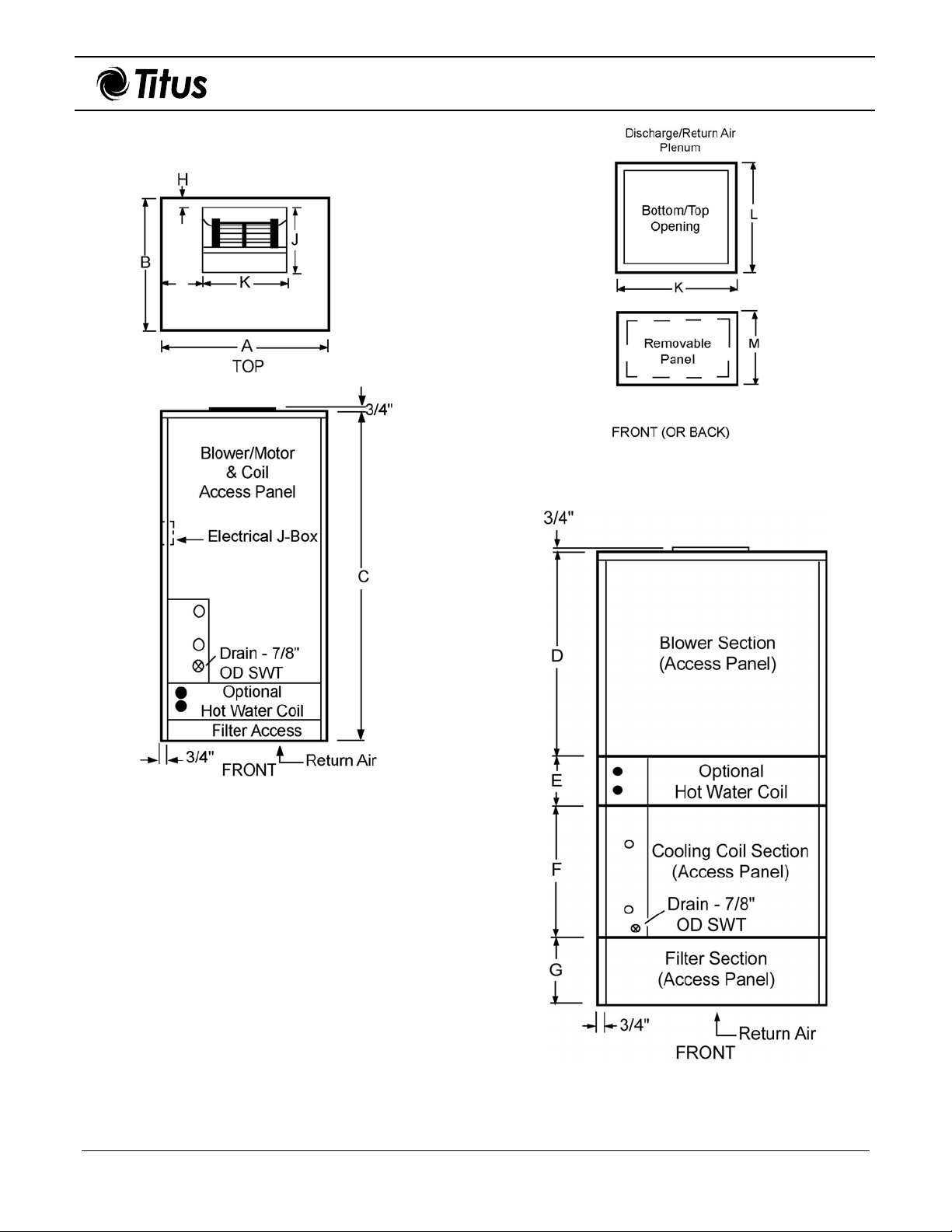
VAB Installation Manual
Figure 3. Optional Discharge or Return Air
IOM-VAB-00 06-30-04
Plenum
Figure 2. VAB08, 12, 16, and 20
Figure 4. VAB30 and 40
3 of 7
Page 4

VAB Installation Manual
IOM-VAB-00 06-30-04
Installation
Basic installation procedure covers verifying and/or
installing the following items.
• Ductwork
• Duct insulation and vapor proofing
• Motors and drives
• Sound attenuation
• Electrical connections
• Condensate drain
• Water piping
Ductwork
Use accepted industry practices and design guidelines of
the ASHRAE Fundamentals Handbook. Ductwork must
comply with all building codes and the National Fire
Protection Association’s pamphlet 90A and 90B.
Carefully inspect any previously installed ductwork to
determine suitability.
Note: Ductwork should be of a size meeting
requirements of the installation. Ductwork should
transition gradually from
required duct run size to avoid excessive loss of air
velocity.
When return air duct connection is smaller than return air
inlet opening, construct the transition piece so the vertical
and horizontal dimensions of transition do not increase
more than one inch for every seven inches of length.
Allow a minimum of three feet of straight ductwork
following an equipment outlet.
a smaller size blower outlet to
Electrical Connections
Each unit has a mounted control box, and typically, the
motor is to be wired to this box. Only ODP, single- and
three-phase motors on 800 t
wired to junction box. All other motors require field wiring
to junction box located on side of the unit cabinet.
Note 1: Unit must be permanently grounded in
accordance with NEC and local codes and ordinances.
See the typical wiring diagrams shown in Figure 5.
Note 2: Not all installations require a starter (some
motors utilize a contactor).
o 2000 CFM units are factory-
Duct Insulation and Vapor Proofing
Previously installed heating supply ductwork may already
have adequate insulation against excessive heat loss.
This insulation may be satisfactory for protection against
heat gain from summer cooling. Depending upon
application, additional
Externally insulated ductwork must have adequate vapor
seal for summer operation, especially where duct is
exposed to high humidity conditions.
insulation may be required.
Motors and Drives
Units are normally shipped with motor and drive installed.
However; when mounting a motor on the adjustable base
in the field, use extreme care to ensure proper alignment
and belt tension.
Sound Attenuation
Flexible duct connections should be used between the unit
and both the supply and return ducts.
Figure 5. Wiring Diagrams
4 of 7
Page 5

VAB Installation Manual
Condensate Drain
Install unit with 1/8-inch pitch toward condensate drain
opening.
Condensate drain must consist of a minimum of ¾-inch
copper tubing, ¾-inch galvanized pipe, or ¾-inch PVC
pipe. Figure 6 shows condensate drain setup. The drain
trap must be properly configured to ensure the removal of
all condensate runoff. Ensure drain pitches downward at a
slope of one inch every 10 feet.
Note 1: Incorrect trapping can hold water in pan,
causing overflow.
Note 2: Consult local codes for additional precautions
before installing condensate drain.
Water Piping
All piping must be supported, independent of coils. Swing
joints or flex
expansion and contraction strains. Rigid piping reduces
the effectiveness of vibration isolators. The water supply
should always be connected so the entering water is on
the leaving airside of the coil. Coils must be adequately
vented in order to prevent air binding.
Note 1: Freeze-ups due to low air temperatures are
not covered under the warranty agreement.
Note 2: Titus recommends a freeze-stat (by others) be
installed when a hot water coil is used and mounted in
the reheat position.
ible fittings must be provided to absorb
IOM-VAB-00 06-30-04
Figure 6. Condensate Drain
Installation of Options
In addition to the standard equipment, the following
optional equipment may require attention du
installation.
• Discharge plenum.
• Return air plenum.
• Two-row hot water heating coil (reheat or preheat
location).
• Electric heat.
• Motor and drive selections.
ring
Discharge / Return Air Plenum
The plenum can be used for either the discharge or return
air as shown in Figure 7. The construction consists of
three permanent sides and one removable panel attached
by screws. This panel may be removed to attach a grille
(not provided) or ductwork and then re-attached to the
plenum. If required, field technicians may choose to cut an
opening in one of the other three sides of the plenum.
Note: The contractor in the field determines the
opening size and
since they are field cut.
location for the grille or ductwork
Figure 7. Optional Plenum Locations
5 of 7
Page 6

VAB Installation Manual
IOM-VAB-00 06-30-04
Electric Heater
Figure 8 shows electric heater components and their
placement and orientation to a VAB unit.
Preparation
Some items to consider prior to installing electric heat are
as follows:
• Duct materials must be suitable for 250º F operation.
See NFPA 90A and 90B pamphlet.
Note: Electric heaters are incompatible with discharge
equipment.
• Ensure ample room exists in the ductwork. Electric
heat must have at least 24 inches of straight duct
clearance before an elbow. If 24 inches are
unavailable, devices such as turning vanes or baffles
may be required.
Installation
Use the following information to install electric heat on
VAB models.
Position heater element section over the blower
1.
wheel of the VAB unit.
Note: Heater baffle must align with blower cutoff scroll. If necessary, rotate heater 180
degrees to align. This ensures proper blower
discharge of air over the heater elements.
Attach electric heat plenum to VAB unit using #6 or
2.
larger sheet metal screws.
Note: Ensure plenum securely attaches to VAB
unit only and not just to blower wheel
extension.
Add insulation, if necessary, to outside of heater
3.
plenum section.
Warning: Do not insulate duct heater.
Startup
Check the following items before startup.
• Ensure all
plus, ensure all other bolts and screws are tight.
• Verify the voltage and phase on the unit nameplate,
and ensure it is the same as the motor wired.
• Check the alignment of the sheaves (pulley wheels)
and ensure the setscrews are tight.
• Check for proper rotation of the blower pulley.
• Check motor phase and rotation.
− Exchanging two of the three leads at the unit
− Exchanging leads inside the motor junction box
− Not all installations require a starter (some
• Ensure all filters are installed.
• Make sure all doors and panels are in place.
• Check the amperage draw of the motor. The
amperage draw should not exceed the nameplate
amps shown on the motor serial plate.
shipping bolts and screws are removed;
junction box can reverse three-phase motor
rotation.
can reverse the rotation of single-phase motors.
Refer to the motor nameplate.
motors utilize a contactor).
Figure 8. VAB Unit with Electric Heater
Components
6 of 7
Page 7

VAB Installation Manual
IOM-VAB-00 06-30-04
Operation and Maintenance
Read and observe the following statements before
operation or maintenance.
DANGER
DISCONNECT ELECTRICAL POWER TO ALL
CIRCUITS BEFORE SERVICING UNIT.
FAILURE TO DO SO MAY RESULT IN PERSONAL
INJURY FROM ELECTRICAL SHOCK OR MOVING
PARTS.
Return Air Filters
Inspect return air filters on a regular basis (at least
monthly). Clean or replace filter(s). Filter can be accessed
from either side of unit.
Caution: Never operate unit without a filter or with
filter access door removed. Damage to blower
motor may result.
Coil
The coil is easily cleaned when dry. To check or clean,
remove blower access panel, filter access door and
filter(s). Use accepted industry methods for cleaning.
Remove all foreign matter from pan and condensate drain
line. Check for rust and holes.
Belt and Pulley
Proper pulley alignment and belt tension must be
maintained at all times.
Reduce speed by adjusting pu
further apart.
Increase speed by moving the faces closer together.
Check pulley setscrews and bolts.
lley faces so the faces are
Abbreviations
The following table lists the abbreviations found within this
document.
Abbrev. Term
ANSI American National Standard Institute
ASHRAE
ASTM
CFM cubic feet per minute
CW chilled water
ETL Environmental Testing Laboratory
fpi fins per inch
fpm feet per minute
HW hot water
IAQ Indoor Air Quality
J-Box Junction Box
lbs pounds
NEC National Electric Code
OD outside diameter
ODP open-drip proof
PSI pounds per square inch
PVC polyvinyl chloride
rpm revolutions per minute
SAE Society of Automotive Engineers
SWT sweat
UL Underwriters Laboratory
wgt. weight
American Society of Heating
Refrigeration Air-Conditioning
Engineers
American Society for Testing and
Materials
Motor
Proper lubrication is essential to long motor life. Use
electric motor oil or SAE20 non-detergent oil. Tighten
motor mount bracket and base bolts.
Note: Avoid over-oiling the motor. If a motor is overoiled, the oil may run down the motor shaft and
splatter.
Blower
Periodically check bearing for wear. Replace as required.
Check wheel for dirt accumulation and clean as required.
7 of 7
Page 8

Air Handler
Terms and Conditions
Warranty
The following terms and conditions apply to and govern
the sale of the air handling equipment and parts
manufactured by Titus.
EXCLUSIVE TERMS OF SALE – Titus quotes and sells its
goods on the expressed condition that the buyer assents to
the terms and conditions set forth herein, regardless of any
inconsistent or additional terms that may be embodied in
any purchase order. Titus’ sale of its goods is expressly
conditional on the buyer’s acceptance and receipt of the
goods shall constitute the buyer’s assent to such terms and
conditions.
ACCEPTANCE – All orders are subject to Credit and Sales
Department approval and acceptance. Titus reserves the
right, among other remedies, to terminate or suspend
further delivery against an order in the event the buyer fails
to pay any portion of the order when it becomes due.
Should buyer’s financial condition become
Titus, cash payment or satisfactory security may be required
by Titus for further deliveries or for goods already delivered.
CANCELLATION – Buyer shall not cancel the order without
prior written consent of Titus. In the event buyer cancels the
order with the prior written consent of Titus after the buyer’s
offer to purchase is received and acknowledged in writing,
Titus shall be entitled to receive from the buyer Titus’ cost
plus 15% administrative overhead and liquidated damages
in the amount of 10%. Furthermore, for goods released for
production but prevented by buyer from shipping upon
completion or by the acknowledged shipping date,
whichever is later, Titus may, at its option, in addition to all
other remedies, invoice buyer to be payable within 30 days
and store the goods at buyer’s
DELIVERIES – Any stated shipping date of the goods is
Titus’ best estimate based upon the volume of orders for the
goods Titus has received or expects to receive at the time it
receives buyer’s order. TITUS MAKES NO GUARANTEE
OF SHIPMENT BY THE ESTIMATED DATE AND SHALL
HAVE NO LIABILITY OR OTHER OBLIGATION,
INCLUDING, BUT NOT LIMITED TO INCIDENTAL OR
CONSEQUENTIAL DAMAGES THE BUYER OR ANY
THIRD PARTY MAY INCURE, FOR ITS FAILURE TO
SHIP BY SUCH DATE, REGARDLESS OF CAUSE.
SHIPMENTS –Titus shall not be bound to deliver any goods
for which buyer has not given shipping instructions. ALL
PRODUCTS ARE SOLD F.O.B. SELLER’
TO GOODS PASSES TO THE BUYER UPON DELIVERY
BY TITUS TO THE FREIGHT LINE. All goods are shipped
at buyer’s risk. Buyer should examine shipments carefully
for loss or damage and should have same noted by
transportation agent on the freight bill upon accepting
delivery. In the event of concealed damage, buyer has 10
days from receipt of the goods in which to call the freight
line for an inspection.
In either case, the equipment cannot be returned to Titus
until after a freight inspection has been completed. In
absence of shipping instructions, Titus shall use its own
discretion in choice of carrier.
TAXES – Sales, use, consumption, storage or other taxes, if
applicable, shall be paid by the buyer.
sole expense.
unsatisfactory to
S PLANT. TITLE
RETURN GOODS – New and unused goods returned for
credit will not be accepted unless a Return Goods
Authorization number has bee
must be securely packed to reach Titus without damage and
properly identified with the Return Goods Authorization
number. RGA numbers are valid for only 30 days after
issuance. A minimum 20% fee will be charged on all stock
products cleared for return that can be returned to stock
after inspection. Build-to-order products manufactured and
shipped cannot be returned and a 100% cancellation fee
applies to any order that has been released for production
but has not shipped. All goods must be returned freight
prepaid by the buyer.
ALL PRODUCTS LIMITED WARRANTY – Titus warrants
that its goods will be free from defects in material and
workmanship under normal use and maintenance for a
period of one year from the date of original installation or 18
months from the date of shipment whichever comes first. A
new or rebuilt part to replace any defective part w
provided without charge, PROVIDED the defective part is
returned to Titus. The replacement part assumes the
unused portion of the warranty.
THIS WARRANTY DOES NOT INCLUDE LABOR or other
costs incurred for identifying, repairing, removing, installing,
shipping, servicing, or handling of either defective parts or
replacement parts.
TITUS WILL NOT BE RESPONSIBLE FOR:
1. Normal maintenance.
2. Damage or repairs required as a consequence of faulty
installation or application by others.
3. Failure to start due to voltage conditions, blown fuses,
open circuit breakers, or other damages due to the
inadequacy or interruption of electrical service.
4. Damage or repairs required as a consequence of any
misapplication, abuse, improper servicing,
unauthorized alteration, or improper operation.
5. Damage as a result of floods, winds, fires, lightning,
accidents, corrosive atmosphere, or other conditions
beyond the control of
6. Parts not supplied or designated by Titus.
7. Titus products installed outside the United States and
Canada.
FOR SERVICE OR REPAIR FOLLOW THESE STEPS IN
ORDER:
FIRST: Contact the installing contractor.
SECOND: Contact the distributor or nearest authorized
Titus representative.
THIRD: Contact
TITUS
990 Secur
Richardson, TX 75080
972.699.1030
THIS WARRANTY IS EXCLUSIVE AND IN LIEU OF ALL
OTHER WARRANTIES EXPRESS OR IMPLIED,
INCLUDING, WITHOUT LIMITATION, THE IMPLIED
WARRANTIES OF MERCHANTABILITY AND FITNESS
FOR A PARTICULAR PURPOSE.
n issued by Titus. Goods
ill be
Titus.
ity Row
1 of 2
Page 9

Terms and Conditions
Warranty
BUYER’S EXCLUSIVE REMEDY – The buyer’s acceptance
of the goods shall confirm the buyer’s review and
acceptance of Titus’ All Products Limited Warranty,
notwithstanding any other written or oral warranty of the
goods that may be given to the buyer. THE BUYER’S
EXCLUSIVE REMEDY AGAINST TITUS SHALL BE
LIMITED TO TITUS’ ALL PRODUCT LIMITED
WARRANTY. NO OTHER REMEDY, INCLUDING, BUT
NOT LIMITED TO, RECOVERY FOR INCIDENTAL OR
CONSEQUENTIAL DAMAGES FOR LOST PROFITS,
LOST SALES, INJURY TO PERSON OR PROPERTY, OR
ANY OTHER INCIDENTAL OR CONSEQUENTIAL LOSS,
SHALL BE AVAILABLE TO THE BUYER.
LD MODIFICATIONS – Should the installing contractor
FIE
believe that the goods do not meet the requirements of the
original submittal or do not operate according to the
submittal, the buyer should immediately contact the selling
distributor or authorized Titus representative as outlined in
the All Products Limited Warranty section. Upon Titus’
acceptance of responsibility to make modifications to the
goods, Titus will, at its sole discretion, either direct the
contractor to make the modifications, send its own field
service technicians to make the modifications, or engage
another contractor to make the modifications. If Titus directs
the installing contractor to make the modifications, Titus will
issue a Field Repair Order (FRO) specifying the work to be
done and the price to be paid. DO NOT BEGIN ANY
MODIFICATIONS WITHOUT AN FRO NUMBER. Titus will
not be responsible
goods, unless it has approved the modifications in advance.
for any costs incurred in modifying the
EXCUSE OF PERFORMANCE – Titus shall not be liable for
its failure to perform due to causes beyond its reasonable
control, including but not limited to strikes, fire, war, acts of
God, whether such events occur at or about Titus’ plant or
at the plant of its suppliers.
CREDIT AND TERMS OF PAYMENT – Unless otherwise
specified, terms of payment are net cash, thirty (30) days
after shipment. Interest at the legal rate applicable to
judgments will be charged on past due accounts
commencing after the last day of the first calendar month
following the date of invoice. Seller may suspend credit and
refuse shipment whenever seller in its sole discretion
believes buyer’s credit is unsatisfactory unless buyer then
makes arrangements for
seller.
MISCELLANEOUS – THESE TERMS AND CONDITIONS
FOR THE SALE OF THE GOODS SHALL BE
CONSTRUED ACCORDING TO THE LAWS OF THE
STATE OF TEXAS. ALL SUMS DUE TITUS FOR THE
SALE OF ITS GOODS ARE PAYABLE, AND ALL
MATTERS ARISING PURSUANT TO SUCH SALE ARE
PERFORMABLE, IN DALLAS COUNTY, TEXAS. The
terms and conditions state herein constitute the full
understanding between Titus and the buyer, and no terms,
conditions, understanding or agreement purporting to
modify or vary these terms shall be binding unless hereafter
made in writing and signed by Titus and the buyer.
Titus has a policy of continuous product improvement,
and reserves the right to cha
specification without notice. Titus has no system
design or application responsibility to buyer or any
third party.
payment which are satisfactory to
nge design and
2 of 2
 Loading...