

Page 1
INSTALLATION &
OPERATION MANUAL
Adjustable
Round Diffusers
TMR/TMR-AA/TMRA/TMRA-AA
Redefine your comfort zone. ™ | www.titus-hvac.com
Page 2
IOM
TMR/TMR-AA/TMRA/TMRA-AA
General Installation
Attach neck of diffuser to duct by screwing through the duct into the neck
of the diffuser.
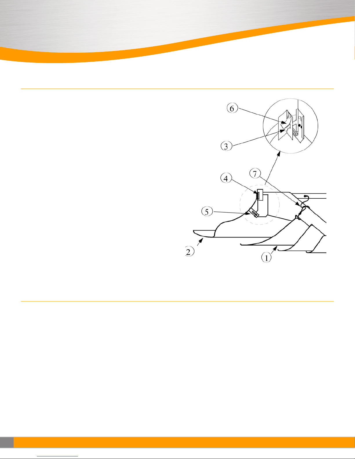
Item Description:
1. Inner cone assembly
2. Outer cone assembly
3. Tang
4. Receptor slot
5. “L” slide retainer
6. Spring clip
7. Safety cable
Note: Safety cables are provided for maintenance purposes to allow the
inner cone assembly to hang during mantenance of the diffuser.
Warning: Cables are not to be removed from installation.
Note: Steps 3 and 4 above apply only to
diffusers with neck sizes of 14” through
36”.
Adjusting Inner Cone Position (TMRA only)
General Installation
STEP 1.
Insert the inner cone assembly upwards into the outer cone assembly
aligning the inner cone assembly tangs with the receptor slots on the
outer cone assembly.
STEP 2.
Rotate the inner cone assembly 10 degrees so that the retainer point has
passed the receptor slot and the weight of the inner cone assembly is
supported by the receptor slots of the outer cone assembly. A set of spring
clips apply pressure to the tangs locking the tangs into the receptor slots.
General installation instrucctions of TMRA, TMRA-AA
STEP 3.
“L” shaped retainer brackets are shipped retracted and must be adjusted
upwards against the outer cone. After installation of the inner cones, as
described above, each “L” slide retainer should be released and extended
upward against the outer cone.
STEP 4.
Lock each “L” slide retainer in place with the screw provided to prevent
release of the tangs on the inner cones from the receptor slots.
Note: Steps 3 and 4 above apply only to diffusers with neck sizes of
14” through 36”.
2
Installation Manual-TMRA
Redefine your comfort zone. ™ | www.titus-hvac.com
Page 3

Adjusting Inner Cone Position (TMRA only)
TYPE 1 INNER CONE:
The type 1 inner cone assembly has three fixed cone positions. The cone
position is adjusted by removing the cone assembly and repositioning it.
To reposition the inner cone assembly, remove the positioning screws and
align the screw hole with the new position desired. Insert and tighten the
screws in the new position.
TYPE 2 INNER CONE: (Steel only, sizes 6”-12”)
The type 2 inner cone assembly is adjusted by sliding the inner cones up
or down as desired.
To reposition the cones loosen the positioning screws and slide the cones
to the new position. Tighten the screws to secure cones in place.
Type 1: 3 Fixed Positions
TYPE 3 INNER CONE:
(Steel only)
The type 3 inner cone assembly is adjusted by rotating the center cone.
To reposition the cones, rotate the center cone clockwise or counter
clockwise to raise or lower the cones.
Type 2: Sliding
Type 3: Rotating
Redefine your comfort zone. ™ | www.titus-hvac.com
Installation Manual-TMRA
3
Page 4

605 Shiloh Rd
Plano TX 75074
ofc: 972.212.4800
fax: 972.212.4884
Redefine your comfort zone. ™ | www.titus-hvac.com
 Loading...