

Page 1
7$2
TAO – Temperature Ambient Optimizer
Floor Mounted Chilled Beam with Perimeter Heating Coil
TAO-IOM-1.1 3-14-14
Receiving Inspection
After unpacking the unit, check it for shipping damage. If
any shipping damage is found, report it immediately to
the delivering carrier. Store units in a clean, dry location
prior to installation.
Installation Instruction
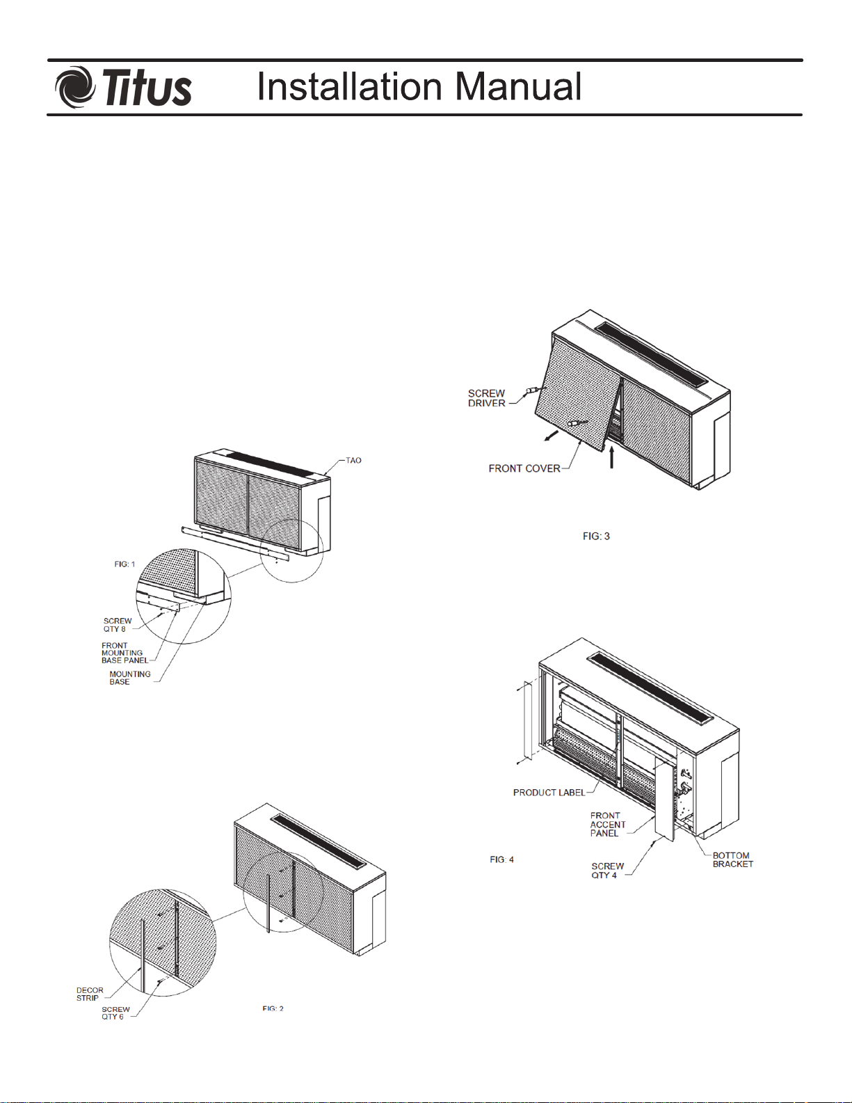
Step 1:
Remove the front mounting base panel by unscrewing it
from the mounting base as shown in Figure 1.
Step 3:
Remove the front cover with the help of two screw
drivers by lifting up and pulling out as shown in Figure 3
to have access to the inside of the unit.
Step 4:
Unscrew the front accent panels. See Figure 4.
Step 2
Uninstall the front cover by taking off the décor strip with
the help of flat head screw driver and unscrewing six
screws as shown in Figure 2.
Page 2
TAO-IOM-2.1 3-14-14
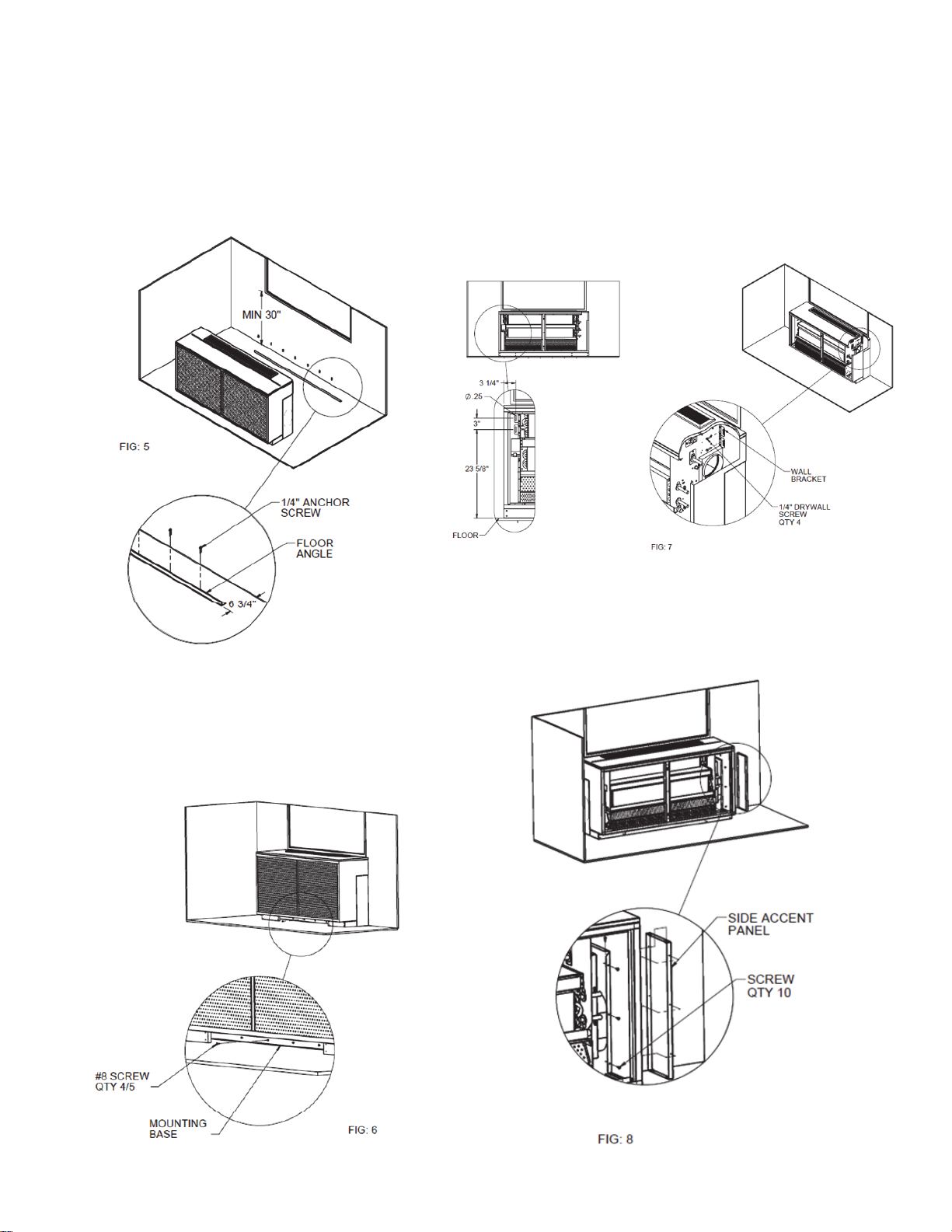
Step 5:
Mount the floor angle to the floor 6 ¾" away from the
wall with the help of anchor screws (not included). See
Figure 5.
Step 7:
To secure the top of the unit to the wall place fasteners
(not included) into the drywall as per the dimensions
provided in Figure 7. Screw the unit to the wall with
drywall screw (not included) in four places as shown in
Figure 7.
Step 8:
To remove side accent panel for duct connections
unscrew the panel in five places from the outer side
panel as shown in Figure 8.
Step 6:
Slide the unit against the wall. Use the slots of the
mounting base to drill hole into the floor angle. Screw
the unit mounting base to the floor angle to secure the
bottom end of the unit as shown in Figure 6.
Page 3
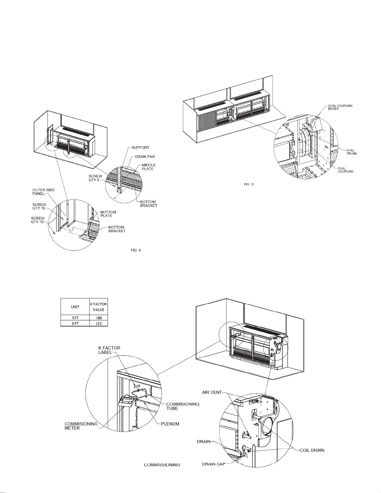
Step 9:
To access the duct work and piping connections remove
outer side panels by unscrewing three screws each from
Top and Bottom plate as shown in Figure 9. Also
unscrew two screws from Top and Bottom brackets from
front as shown in Figure 9.
To remove the drain pan for cleaning purpose unscrew
the center support in six places as shown in Figure 9
and slide the drain pan out.
TAO-IOM-3.1 3-14-14
Step 10:
To connect oval trunk of two units in series use oval
coupling (option) as shown in Figure 10 and seal it with
duct sealant to avoid leakage.
Primary Airflow Commissioning
For commissioning remove the left front cover as shown in Figure 2 and Figure 3. Take off the pipe cap and use the commissioning
tube to obtain the internal pressure of the plenum as shown in Fig 11. The K-factor of the unit is stated on K-factor label mounted on left
inner side panel on top of the commissioning tube mount. The K-factor can also be found on our website in the relevant K-factor guide.
 Loading...