

Page 1
TAF-L Perimeter System
INSTALLATION MANUAL
TAF-L Underfloor Perimeter System
CT-TAF-L
TAF-L-W
TAF-L-V
TAF-L-E
TAF-L-F
TAF-L-R
Redefine your comfort zone. ™ | www.titus-hvac.com
Page 2
TAF-L Underfloor Perimeter System
TAF-L Perimeter System IOM
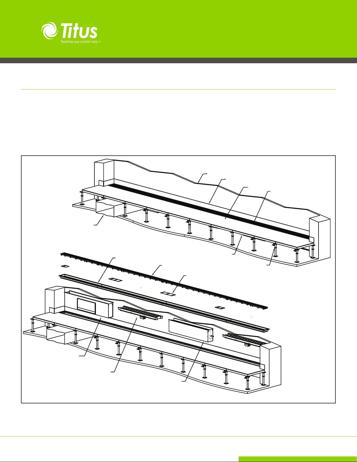
The TAF-L underfloor perimeter system consists of a series of plenum
boxes under linear runs of CT-TAF-L diffuser along the perimeter of a
building. The TAF-L-V plenum provides cooling, the TAF-L-W provides
heating, and the TAF-L-R provides a return.
The TAF-L-V cooling unit has a variable linear bar diffuser with a series of
apertures through which the air exits. The TAF-L-W heating plenum has
a hot water fin tube heater assembly in the plenum.
Rigid Duct From Return Plenum
To Fan Box (Supplied By Others)
CT-TAF-L Diffuser Frame
CT-TAF-L Diffuser Core
The CT-TAF-L core itself has a specific wing configuration designed to
deflect the air and provide throw reduction. Figure 1 below shows all the
major components of the system and their typical installation.
Wall
Baseboard
Floor Tile
Carpet
Pedestal
Perimeter Diffuser Assembly
TAF-L-R Return Plenum
20" X 8" Opening For Butt
Connected Rigid Duct
TAF-L-V Cooling Unit
with Actuated Aperture Plates
Figure 1 - Typical Finished Installation
Blankoff Plates As Needed
To Fill Space Between Plenums
TAF-L-W Heating Plenum
2
Installation Manual - TAF-L Perimeter System
Redefine your comfort zone. ™ | www.titus-hvac.com
Page 3
TAF-L Underfloor Perimeter System
TAF-L Perimeter System IOM
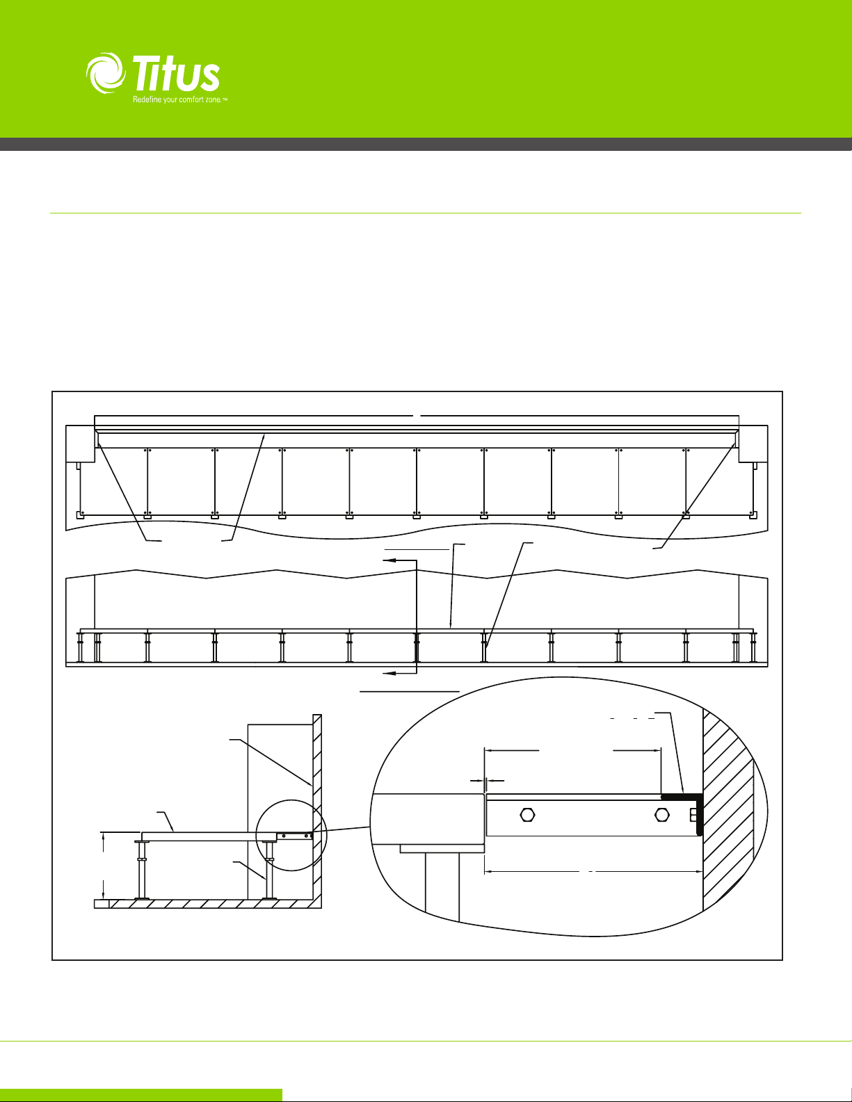
Wall Angle Placement
Attach a 11/4” x 11/4” x 3/16” angle to the wall where the perimeter
diffuser Assembly will be installed. This includes the long span between
columns and the short section along each column.
The angle should be installed level with top of the desired floor tile
height. The angle will carry half the weight of the diffuser assembly.
See Figure 2.
Angle
Angle
PLAN VIEW
A
Floor Tile Placement
Install raised floor tiles with a 61/2” space between the edge of the tile
and the wall. The top of the angle needs to be level with the top of the
floor tiles. See Figure 2.
There needs to be an opening of 61/4” (+/-1/8”) between the floor tile
edge and the angle edge. If wall variations result in less than a 1/8”
slot, the angle shall be ground down to within tolerance.
5566.44 (APPROX. DISTANCE BETWEEN COLUMNS)
Floor Tile
Pedestal
Angle
Wall
Floor Tile
Floor Tile
Height
* All dimensions are in inches
Pedestal
SECTION A-A
Figure 2 - Floor Tile and Angle Placement
Redefine your comfort zone. ™ | www.titus-hvac.com
A
ELEVATION VIEW
6 1/4" +/- 1/8"
Opening for
Perimeter Grille
Minimal Gap
ANGLE
3
1
1
X 1
X
1
4
4
16
1
6
2
Installation Manual - TAF-L Perimeter System
3
Page 4

TAF-L Underfloor Perimeter System
TAF-L Perimeter System IOM
Plenum Installation
Install the desired plenums by placing them into the slot between the
floor tiles and the angle. Plenums should be placed such that thermostats are not in a direct airflow from the plenums.
TAF-L-R Return Plenum
Position TAF-L-R ducted return plenums first. These plenums have a
20”x8” rectangular opening for a rigid duct connection to a fan box.
Center the duct opening between two floor pedestals. The TAF-L-R return
plenum has four flanges that can manually be bent out 90° in order help
in the installation of the duct.
The duct should have a butt type connection and can the secured to the
plenum by driving self-drilling sheet metal screws into the side of the
plenum.
Removal of one or more floor tiles may be necessary to help with the
connection of the duct. See Figure 3.
TAF-L-W Heating Plenum
Position TAF-L-W heating plenums next as hot water piping has to be
connected. The unit has 2 ½” of straight copper tubing extending beyond both sides of the plenum for field connections. Note the orientation
of the unit as the hot water tubing should be located on the exterior wall
side of the building per the section view shown in figure 8 on page 6.
Removal of a floor tile may be necessary to help with tubing connections.
Ducted TAF-L-R
Return Plenum
Duct Alignment Tabs
Bent Out As Needed
(Duct Not Shown)
Figure 3 - Plenum Installation
4
Installation Manual - TAF-L Perimeter System
TAF-L-W
Heating Plenum
TAF-L-R Return Plenum Must
Be Centered Between Pedestals
ELEVATION VIEW
PLAN VIEW
Actuated TAF-L-V
Cooling Unit
TAF-L-W
Heating Plenum
copper piping between TAF-L-W heating
plenums. (Piping runs beneath the cooling
TAF-L-V units.)
Redefine your comfort zone. ™ | www.titus-hvac.com
Page 5

TAF-L Underfloor Perimeter System
TAF-L Perimeter System IOM
TAF-L-V Cooling Plenum
Position the actuated TAF-L-V cooling units last. Make the necessary
electrical connections to the actuator (shown on page 8) before placing
the unit in the slot .
Place the TAF-L-V units in the slots such that the aperture plates all actuate in the same direction.
Carpeting
Lay carpeting up to the edge of the floor tile and along the angle. Carpeting will cover the plenum flanges. See Figure 5.
C
C
ELEVATION VIEW
CT-TAF-L Frame
The CT-TAF-L diffuser frame is supplied in multiple sections. Each section
goes into the slot and sits on top of the carpeting.
Place the frame sections into their appropriate positions in the slot. See
Figure 5. A maximum of ½” may be cut off of any ‘Y’ frame end. Alignment clips may no longer fit if a section has been cut. Never cut off the
last frame cross support bar!
See page 5 for alignment clip installation instructions.
Plenum End Cap
CT-TAF-L Frame
Carpet
Cove Molding
Carpet
1
"
2
Actuator
Figure 5 - Carpet & Frame Installation
Redefine your comfort zone. ™ | www.titus-hvac.com
SECTION C-C
Wall
Installation Manual - TAF-L Perimeter System
5
Page 6

TAF-L Underfloor Perimeter System
CT-TAF-L Frame (cont.)
Frame sections can the aligned with the use of a frame alignment clip.
The clip snaps onto the bottom stackhead of the frame extrusion and is
placed partially on the end of two sections that butt to one another.
#8 TEK SCREW
4 PLCS
727979-00
ALIGNMENT BRACKET
1 PER JOINT
TAF-L Perimeter System IOM
AT TACH ALIGNMENT BRACKE T
TO CROSS BRACE
DETAIL A
CT FRAME JOINT
A
6
Installation Manual - TAF-L Perimeter System
Redefine your comfort zone. ™ | www.titus-hvac.com
Page 7

TAF-L Underfloor Perimeter System
TAF-L Perimeter System IOM
CT-TAF-L Blank-off Plate
There will be openings between plenums and between plenum ends
and the CT-TAF-L frame ends. Measure these openings and cut blank-off
plates to fit into these gaps. Be sure and follow the following guidelines
for cutting blank-off plates. See Figure 6.
Blank-off plates must lie below the core support bars and a core support
bar cannot sit on a blank-off support strip. (Core will not sit level and
will rock)
Blank-off Plate
3" Max
Where possible, have at least 2 support strips per cut section to keep the
blank-off plate from falling into the under floor plenum space.
Leave no more than 3 inches from the edge of a support strip to the edge
of the blank-off plate. Sections longer than 3 inches may cause the plate
to sag and vibrate.
Aperture Installation Notes:
1. Position Plates On Frame And Inside Plenum Ends
2. Measure Open Space Between Plenums
3. Cut And Install Blank-Off Plates
Blank-off Plate
Tabs will sit
on Frame
Figure 6 - Aperture Plate & Blank-Off Installation
Redefine your comfort zone. ™ | www.titus-hvac.com
Installation Manual - TAF-L Perimeter System
7
Page 8

TAF-L Underfloor Perimeter System
CT-TAF-L Core
Place the CT-TAF-L cores into the frames with orientation shown in Figures 7 and 8 below. With this orientation, air deflection will be into the
room and not against the wall.
A maximum of ¾” may by cut to from each core end. Never cut off the
last core support bar! Doing so may result in unsupported core wings
which will not support foot traffic.
TAF-L Perimeter System IOM
Room Side Wall Side
Figure 7 - Proper Core Orientation in Frame
Rigid
Duct
20"X9"
TAF-L-R Return Section
F
F
TAF-L-V Cooling Section
G
G
BLOCK
ELEVATION VIEW
TAF-L-W Heating Section
H
H
ACTUATOR
TAF-L-V Cooling Section
3/4" COPPER TUBE
TAF-L-R
RETURN PLENUM
SECTION F-F
Figure 8 - Complete Installation
Note: The TAF-L-V is designed so that the tubing which connects the TAF-L-W together runs just beneath the TAF-L-V unit as to avoid tube interference.
8
Installation Manual - TAF-L Perimeter System
TAF-L-V
COOLING UNIT
SECTION G-G
TAF-L-W
HEATING UNIT
SECTION H-H
Redefine your comfort zone. ™ | www.titus-hvac.com
Page 9

TAF-L Perimeter System IOM
TAF-L Underfloor Perimeter System
TAF-L-V Wiring Diagrams / UnderFloor Diffuser Series / Linear Diffuser Plenum with Variable Aperture Plate
Modulating (0-10V) Diagram
Code ET03
Notes:
1. A maximum of 20 actuators may be daisy chained per thermostat.
2. Wire numbers on the diagram for the TAF-L-V are written on the wires coming off the actuator.
3. Connection codes on the thermostat above are for the Siemens RDU50U. Please use the descriptions as it pertains to the equivalent stat being
used.
Modulating (3-Point Floating) Diagram
Code ET04
Notes:
1. A maximum of 20 actuators may be daisy chained per thermostat.
2. Wire numbers on the diagram for the TAF-L-V are written on the wires coming off the actuator.
3. Connection codes on the thermostat above are for the Siemens RDU50U. Please use the descriptions as it pertains to the equivalent stat being
used.
Redefine your comfort zone. ™ | www.titus-hvac.com
Installation Manual - TAF-L Perimeter System
9
Page 10

The TAF-L Perimeter System was designed to address the challenges of handling perimeter loads in a modular system. The
TAF-L Perimeter System consists of a modular cooling plenum, the TAF-L-V, and heating plenum, the TAF-L-W, designed to
be integrated with the CT-TAF-L multi-deflection linear bar diffuser.
CT-TAF-L
A fixed linear bar diffuser for underfloor perimeter return applications. The CT-TAF-L integrates with all the TAF-L plenums
from above to provide the necessary air distribution.
605 Shiloh Rd
Plano TX 75074
ofc: 972.212.4800
fax: 972.212.4884
 Loading...