

Page 1
T3SQ-4-IOM-3.0 05-17-07
Installation, Operation & Maintenance of the T3SQ Thermal
VAV Diffuser
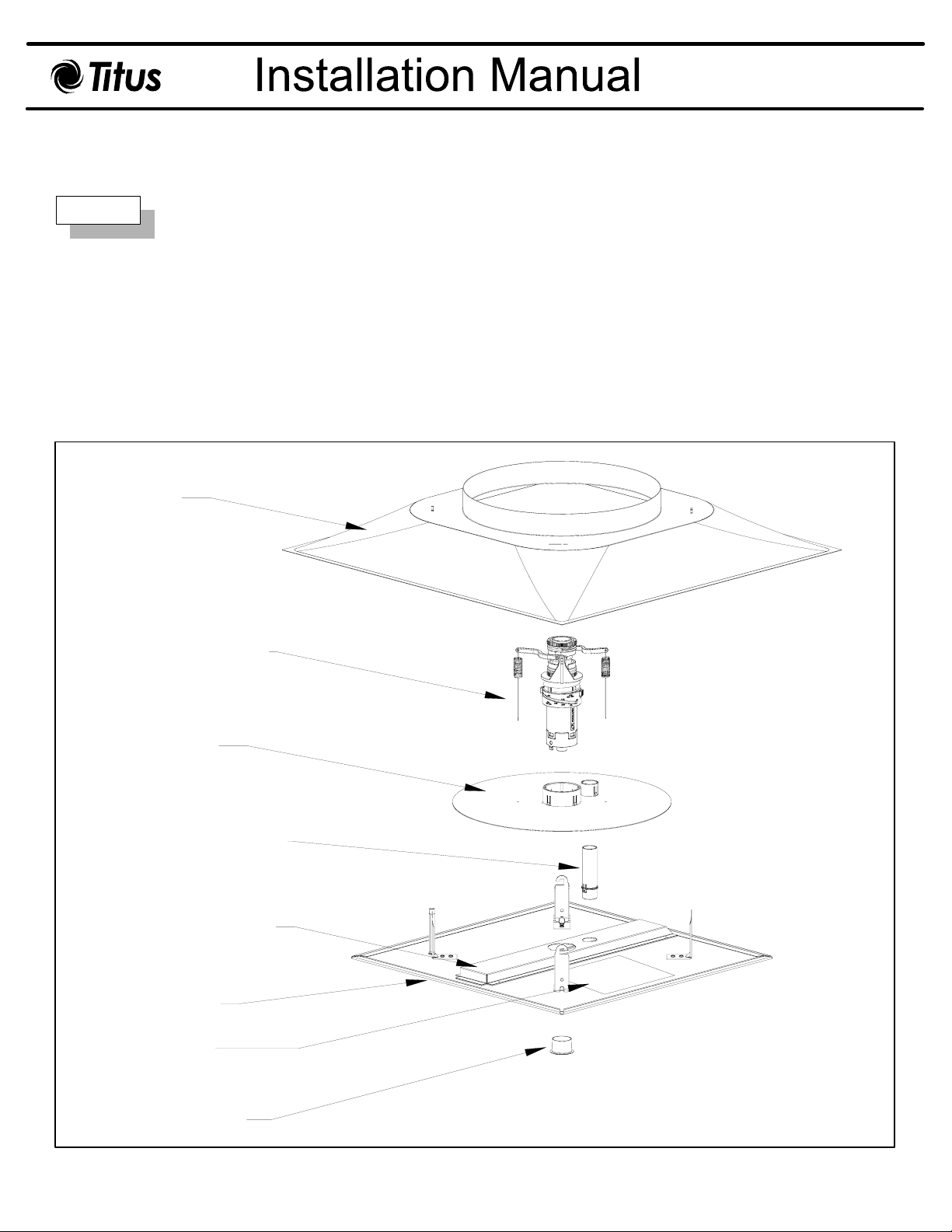
Step 1
The units should be shipped assembled except for the backpan.
Remove all packaging from the components. The thermal T
protect the actuator assembly. Be sure to remove packaging between the diffuser plaque and the control
disc. Make sure that no packaging is obstructing the thermal element at the top of the actuator or the
induction cap on the plaque.
If unit is not assembled, follow the steps below before proceeding (See Figure 1):
1. Insert induction cap into plaque of diffuser.
2. Insert venturi tube into induction channel until
3. Slide control disc over venturi tube.
4. Insert actuator through center hole in the control disc and snap into induction channel.
Backpan
Thermal Actuator
3
tabs engage.
SQ is shipped with additional packaging to
Control Disc
Venturi Tube
Induction Channel
Face Plaque
IOM Label
Induction Cap
Figure 1. T3SQ-4 Parts & Assembly
Page 2
T3SQ-4-IOM-3.0 05-17-07
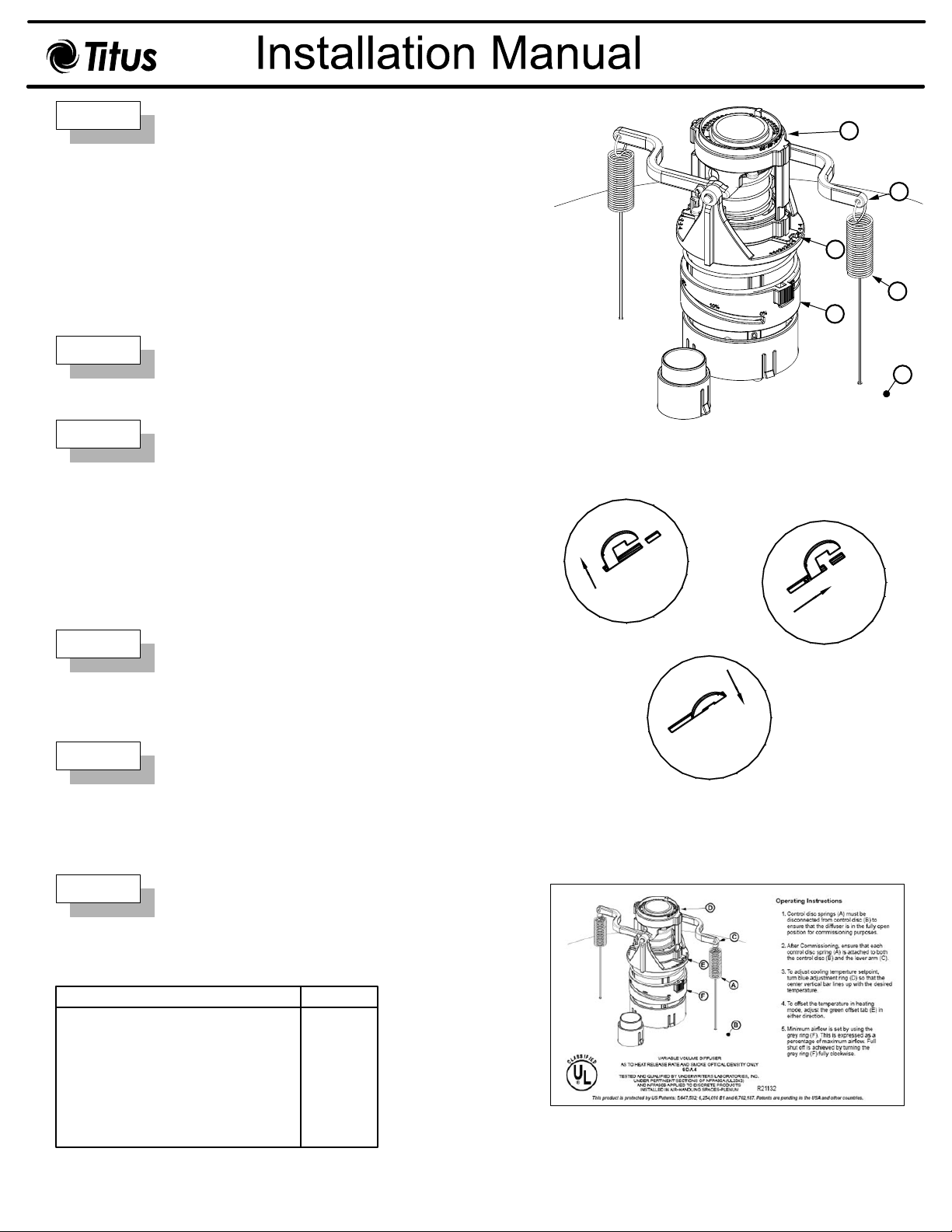
Step 2
Step 3
Step 4
Step 5
For system balancing, the springs (A) must be
disconnected from the control disc (B) to allow the
control disc to go to full open. (See Figure 2)
After balancing, reconnect the springs to the control
disc. If the actuator arms are not connected to the
control disc the diffuser will not operate.
Ensure that each control disc spring (A) is attached
to both the control disc (B) and the lever arm (C)
before installing.
Place the back pan into ceiling grid. Connect duct
work to back pan.
Adjust room temperature:
Turn the blue ring assembly (D) to the desired
temperature indicated ( 66°F to 74°F)
To adjust the offset differential between heating
and cooling, turn the green tab (E) clockwise to
increase positive temperature offset and
counterclockwise to increase temperature offset in
a negative direction.
Minimum airflow can be adjusted from 30% of
maximum down to fully closed or 0% of maximum
by turning the grey flow adjustment ring (F)
clockwise.
D
C
E
A
F
B
Figure 2. T3SQ Thermal Actuator and Control Disc Assembly
1.
2.
Step 6
Installation is completed by lining up the hooks on
the face plaque assembly with the corresponding
3.
slot. The hooks are inserted and the face plate
assembly is rotated clockwise, and lowered so
that each hook is firmly in place. (See Figure 3)
Figure 3. Face Plaque Installation
Note:
A simplified version of these operating instructions
can be found on the plaque of each diffuser.
(See Figure 4)
Thermal - T
Heating / Cooling Actuator
Venturi Tube
Venturi Tube Guide
Control Disc Sleeve
Control Disc
Thermal Induction Channel
Induction Cap
Plaque/Actuator/Control Disc Assy T3SQ-4
Note: This IOM is meant to demonstrate general dimensions of this product. The drawings on this IOM are not meant to detail every aspect of the product with exactness. Drawings are not to scale.
All rights reserved. No part of this work may be reproduced or transmitted in any form or any means, electronic or mechanical, including photocopying and recording, or by any information storage retrieval system without permission in writing from Air Distribution Technologies.
SQ-4 Replacement Parts
3
Description Part Number
38203201
72540201
72540301
72540401
72540501
78200201
72549501
31763101
Figure 4. T3SQ-4 Operating Instruction Label
TITUS reserves the right to make changes without written notice.
 Loading...