

Page 1
thermostat operating manual
Digital t3SQ
Digital t3SQ
www.titus-hvac.com | www.titus-energysolutions.com
Page 2
Thermostat
O P E R AT I N G M A N UA L
Introduction
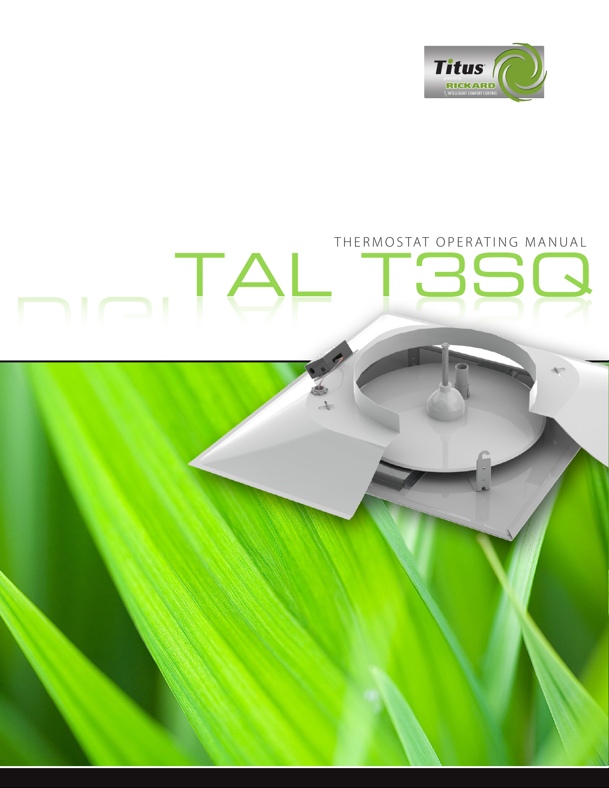
This Setup module is fitted with an LCD display. The adjuster is supplied in an aesthetically pleasing, compact 3”
by 3 ¼” plastic enclosure. The unit provides for the commissioning and configuration of Titus MLM controllers.
The unit is plugged into any open RJ12 socket provided on
the set of diffusers connected to a power pack. One RJ12
socket is available on the back of the diffuser tile on the
MLM connection box and the other RJ12 socket is available
in the trim of the diffuser on the MLM interface board.
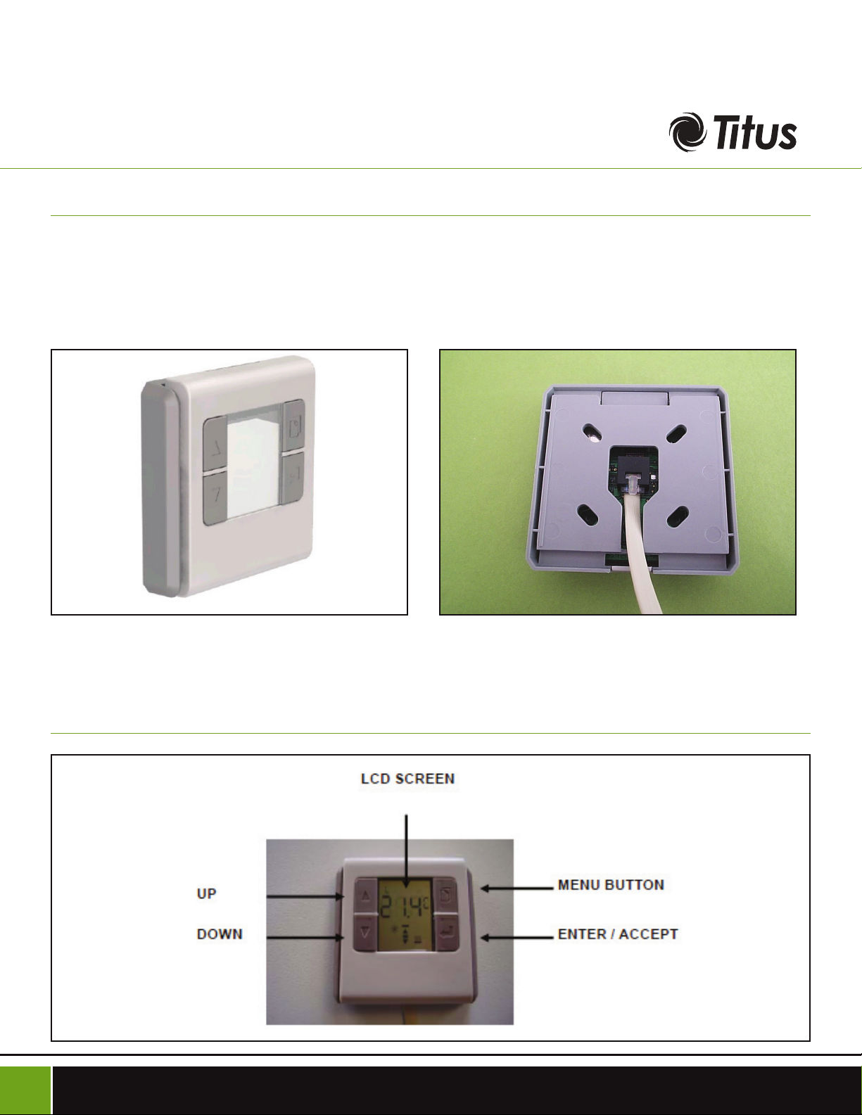
Operating Panel General
Thermostat Operating Manual - T3SQ-2
2
Page 3

Important Rules
ON COMMISSIONING A SET OF DIFFUSERS WITH THE SETUP
MODULE THE FOLLOWING IMPORTANT RULES MUST BE AD
HERED TO:
- Per temperature control zone, one MLM wall-stat is allowed for. Thus if there are fifteen diffusers connected to
a power pack controlling three zones, a maximum of three
wall-stats and/or three analog modules is allowed, one of
each per control zone.
- To set up the control zones, the Setup Module can be
connected to any RJ12 socket on that set of diffusers connected to a power pack – it does not have to be plugged
in at the zone being set up. The Setup Module can be
plugged in while the system is powered up, without resetting the controls.
- To change or select any parameter barring the selection
Operating Instructions
On start-up (power on), the version number will be displayed.
Subsequently the Diagnostic icon is flashed while the unit
collects information from the control system.
Once this information is accumulated, the setup module will
mimic and display the status of the current control zone it
is plugged into. Should no zone be selected at this stage,
the status display is indeterminate and the top left character display will indicate ‘CE’ for control external.
To enter the sub menus, keep the menu button pressed
until the unit beeps.
of control zones, the Setup Module must be plugged into
a diffuser in that particular control zone. It is therefore important to first select the diffusers for a control zone or be
sure it has been selected previously, before changing any
other parameter.
- By factory default each wall-stat and each analog module has the setpoint, room temperature and CO functions
selected. Thus should the installation consist of only a wallstat or an analog module per control zone, the configuration in above is not required.
- The information changes are periodic and some patience
is required while parameters are being exchanged.
- Changing parameters is non-volatile and once selected
and accepted by the system will be permanently stored.
The display will show the current control disk position in
percentage, with the top left character display indicating
‘dr’ for motor drive.
To manually drive the disk, press the up/down arrows
for the required position and press enter.
The double bar icon will flash to indicate the motor is
manually controlled.
Verify the disk movement of all diffusers in that control
zone and the position display update.
SUB M SUPPLY AIR TEMPERATURE
The top left character display will indicate ‘CO’ for changeover or supply air temperature value. A value of zero indicates the CO sensor is not selected or not connected.
To advance to the next menu, press the menu select button.
SUB M CONTROL DISK POSITION
To advance to the next menu, press the menu button.
The control will revert back to automatic.
SUB M
The display will show the open end-stop disk position in
percentage, with the top left character display indicating
‘dr’. The down arrow and single bar will flash to indicate
‘open end-stop’
CONTROL DISK O OP
Thermostat Operating Manual - T3SQ-2
3
Page 4

Thermostat
O P E R AT I N G M A N UA L
To change the open end-stop position, press the up/
down arrows for the required position and press enter.
The display will flash ‘---‘ until the new parameter is
accepted by the system.
Should the disk be outside the end-stop range it will
manually drive the diffusers in that control zone into
range.
To advance to the next menu, press the menu button.
SUB M CONTROL DISK CLO OP
The display will show the close end-stop disk position in
percentage, with the top left character display indicating
‘dr’. The up arrow and bar will flash to indicate ‘close end-
stop’
To change the close end-stop position, press the up/
down arrows for the required position and press enter.
value is accepted and the heater in that zone controlled
to the new value.
To advance to the next menu, press the menu select
button. The control will revert back to automatic.
SUB M
To bind a diffuser to a control zone the following steps is
required:
The top left character display will indicate ‘LS’ for Loop
Select.
Keep the enter button pressed until the unit beeps.
The menu display ‘L and a zone number, ‘00’. If the
zone has been set up previously, that particular zone
number will display iso the ‘00’.
Press enter again and the zone number will flash.
CONTROL ZONE S LOO
The display will flash ‘---‘ until the new parameter is
accepted by the system.
Should the disk be outside the end-stop range it will
manually drive the diffusers in that control zone into
range.
To advance to the next menu, press the menu button.
SUB M HEATER OUTPUT
The display will show the current heater output in percentage, with the top left character display indicating ‘Ht’.
To manually drive the heater output, press the up/
down arrows for the required position and press enter.
The heater icon will flash to indicate the heater is
manually controlled.
The character display will indicate zero until the new
Use the up/down arrow to select a zone number. On a
new installation always start with zone ‘1’.
Press enter and observe the ‘L’ starting to flash.
Go to the first diffuser in that zone and press the
button on the MLM MD board, normally situated on the
trim disk.
After a few seconds the Setup Module will beep and
the flashing LED on the MLM MD board will stay
switched on momentarily – both to indicated the
diffuser is set up for that control zone.
Go to the next diffuser in that zone and press the
button again and observe the same result. All the while
the ‘L’ indicator will flash and the zone number will be
on permanently.
Continue the process until all the diffusers in the
control zone has been selected.
Thermostat Operating Manual - T3SQ-2
4
Page 5

Press the enter button and observe the ‘L’ stationary
and the zone number flashing.
must be a wall-stat connected to that particular control
zone.
Using the up/down arrows, select the next zone
number and press enter.
Using the same procedure set up each diffuser in the
control zone of interest.
A maximum of fifteen control zones (one diffuser per
zone) can be set up. By the same token a minimum
of one zone containing from one to fifteen diffusers
(slaves) can also be set up.
Press enter again to exit the last zone setup.
To advance to the next menu, press the menu button.
SUB M CONTROL INPUT SELECT
The next function is to select the setpoint, control and
supply air temperatures for a particular control zone. As
mentioned, to use this function the setup module must
be connected to a diffuser in the control zone of interest.
On a default system with only one wall-stat or one analog
module connected to a control zone this function won’t be
required.
The display will indicate ‘tS’ in the top left character
display.
Press enter and the character ‘S’ will show to indicate
setpoint selection. The up/down arrows will toggle this
function.
Press enter to select the supply air input, character ‘C’.
The arrow buttons will toggle between ‘o’, ‘r’ and ‘-‘ if
supply air measurement is not required.
On pressing enter again the three characters will flash
until the system has accepted the new setup.
Press the menu button to exit this function.
To advance to the next menu, press the menu button.
SUB M SETPOINT ADJUST
The next function displayed is setpoint adjust with the ‘SP’
icon on.
Note the setup module must be plugged into the
control zone of interest for this function.
The top left character display will indicate ‘S1’ for
setpoint 1. Setpoint 2, or the back off setpoint is not
adjustable with this unit.
The character display will indicate the current status of
the three control inputs as follows:
‘o’ - indicates ‘on-board’ for analog module.
‘r’ - indicates ‘remote’ for wall-stat
‘-‘ - indicates not selected
Keep the enter button pressed until the unit beeps. The
first character will flash with the display indicating ‘t’ for
control temperature selection.
Pressing the up/down arrows will toggle between
remote or on-board temperature selections. Be sure to
select a valid option, ie when selecting ‘remote’ there
Press the up/down arrow to select the required
setpoint. The digits will flash.
Press enter. The display will flash ‘---‘ until the new
setpoint has been accepted.
Press the menu button to exit this function and revert
to the main menu.
Thermostat Operating Manual - T3SQ-2
5
Page 6

The Digital T3SQ is the most energy ecient VAV diuser on the market. It only requires 1 VA max per diuser and the commu-
nication modules allows for interfacing with building management systems for all major communication protocols. With user
friendly software to control and commission diusers, the Digital T3SQ is the next level of VAV diusers on the market.
T3SQ-2
The T3SQ combines the functions of a VAV terminal and a high performance diffuser in one by
modulating the air volume delivered to a zone to
accurately control cooling and heating conditions.
This results in maximum air distribution effectiveness at any airow, for superior comfort conditions.
605 Shiloh Road
Plano TX 75074
Oce: 972.212.4800
Fax: 972.212.4802
Email: titus@titus-hvac.com
 Loading...