

Page 1
T3SQ-1-IOM-1.0 6-6-09
Installation, Operation & Maintenance of the T3SQ Analog
VAV Diffuser
Step 1
The units should be shipped assembled except for the backpan. The thermal T
additional packaging to protect the actuator assembly. Remove all packaging from the components.
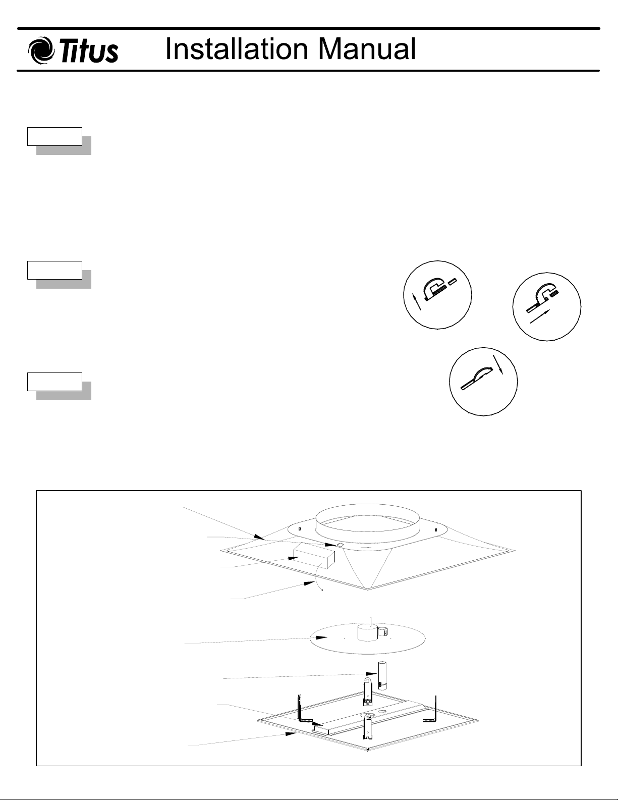
If the unit is not assembled, follow the steps below before proceeding (see Figure 1):
1. Insert the control disc guide into the control disc.
2. Screw the bottom of the actuator / control disc assembly into the mounting channel.
SQ is shipped with
3
Note: The T3SQ-1 diffuser is shipped as a dummy unit. Master and drone operation is
determined by the wiring – discussed in Step 3. Master and drone locations are not needed
at this point in installation.
Step 2
Step 3
Place the back pan into ceiling grid. Connect duct work to back
pan. Insert the supply air temperature sensor into the supply
duct. If the unit has an optional inlet heater, the supply air
sensor must be positioned above the heater in the supply duct.
Set minimum airflow by adjusting
actuator shaft. 0.5" down from the top of the shaft allows the
diffuser to go to the full closed position.
Installation is completed by lining up the hooks on the face
plaque assembly with the corresponding slot. Insert the RJ-45
cable on actuator / control disc assembly through wiring conduit.
The hooks are inserted and the face plaque assembly is rotated
clockwise, and lowered so that each hook is firmly in place. (See
Figure 2)
the brass nuts at the top of the
1.
2.
3.
Figure 2. Face Panel Installation
Plug the RJ-45 cable on actuator / control disc assembly into
any RJ-45 jack on the wiring interface box on the backpan.
Backpan
Conduit for Wiring
Wiring Interface Box
Supply Air Temperature
Sensor
Actuator / Control Disc
Assembly
Control Disc Guide
Mounting Channel
Face Plaque
Figure 1. T3SQ-1 Assembly
Page 2
T3SQ-1-IOM-2.0 6-6-09
Step 4
Wiring Instructions:
T3SQ-1 diffusers are all shipped as dummy units. Determination of
master and drone units is made through plug and play cable
connections.
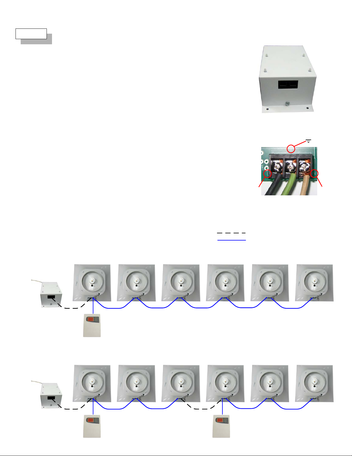
One power module is required for every six (6) diffusers without electric
reheat or every five (5) diffusers with electric reheat. (See Figure 3)
Power module requires 120VAC line voltage input – hardwired by
others. (See Figure 4)
Master diffusers must be connected to a controller / thermostat. (See
Master Controller / Thermostat section on next page for details.) Drone
diffusers must be connected to a master diffuser. Disconnect the
supply air temperature sensor on all drone units.
White RJ-12 6-pin cables provide 24VAC power between diffusers.
RJ-12 cables should be used between the power module and the first
diffuser and to connect a master unit to another master unit. The RJ-12
jacks are interchangeable – either RJ-12 jack may be used during
installation. (See Example below)
Blue RJ-45 8-pin cables provide 24VAC power and control signal
between diffusers. RJ-45 cables should be used between diffuser and
master controller / thermostat and between master and drone units.
Disconnect the supply air temperature sensor on all drone units.
Figure 3. T3PM Power Module
al
d
r
t
n
L
Figure 4. T
t
o
H
Grou
PM Power Module Wiring
3
u
e
N
N
The RJ-45 jacks are interchangeable – any open RJ-45 jack may be
used during installation. (See Example below)
Examples:
One master unit controlling 5 drone units:
Master unit Drone unit Drone unit Drone unit Drone unit Drone unit
120V input, field
wiring by others
24V output
to diffusers
Two master units controlling 2 drone units each:
Master unit Drone unit Drone unit Drone unit Drone unit
120V input, field
wiring by others
RJ-12 24V power only
RJ-45 power and control signal
Master unit
24V output
to diffusers
Page 3

Master Controller / Thermostat Operation
When power is supplied to the diffusers and the controller / thermostat, the
controller / thermostat will drive the diffusers to full closed to calibrate the
movement of the master and drone units. During this startup operation the
controller / thermostat will display “ST”.
The controller / thermostat normally displays room temperature.
The Cool and Heat indicator lights show the mode of operation that the unit
is in. If the zone is above setpoint, the Cool indicator will be lit to show that
the zone requires more cooling. If the zone is below setpoint, the Heat
indicator will be lit to show that the zone requires more heating.
To adjust the setpoint adjustment press either button. An audible sound will
let you know the button was pressed. The current setpoint value will flash
on the display. Default setpoint is 71º F (22º C). Press the up or down
arrow buttons to increase or decrease the setpoint. The setpoint
adjustment function will exit after 5 seconds of no user input.
T3SQ-1-IOM-3.0 6-6-09
To drive the damper full open or full closed, you must put the controller /
thermostat into override mode. Override mode should be used for
commissioning. Press the down arrow for 5 seconds until display will read
“LI” to indicate the override mode.
Pressing the up arrow will drive the damper to the closed position. Pressing
the down arrow will drive the damper to the open position. Pressing both
buttons simultaneously will take the unit out of override mode.
Press the up arrow on the controller / thermostat for 5 seconds to display
supply air temperature. A display of “00” denotes that a changeover sensor
is not being used. The display will revert back to zone temperature after 5
seconds.
Optional Inlet Heater Operation
The optional SCR controlled inlet electric heater is mounted in the neck of
SQ-1 diffuser. (Line voltage must be supplied to the electric heaters.)
the T
3
If the inlet heater is used with the T
through the wiring interface board on the heater assembly instead of the
wiring interface board on the diffuser backpan. The wiring interface board
on the diffuser may be discarded or ignored. The power wiring to the heater
has to be connected by removing the face from the wiring interface board
enclosure per Figure 7. The wires must be routed through the grommets,
connected to L & N, and then re-attach the face of the enclosure.
SQ-1, all wiring should be connected
3
Figure 5. Master Controller / Thermostat
Figure 6. Optional Inlet Heater
The controller / thermostat will energize the inlet heater when the zone
temperature is 1
a time pulsed signal from minimum output to full output over a 2
temperature range. At 3
An airflow switch and two thermal cutouts protect the heater from operation
without airflow or at temperatures above 200
o
F below setpoint. The SCR heater controller will modulate
o
F over setpoint the heater will be at full output.
o
F.
o
F
Figure 7. Optional Inlet Heater Wiring
Page 4

Replacement Parts
T3SQ-1-IOM-4.0 6-6-09
Description Part Number
Master Controller / Thermostat
PM - 120V/24VAC Power Module
T
3
Blue RJ-45 Power and Control Cable
White RJ-12 Power Cable
Actuator / Control Disc Assembly
Supply Air Temperature Changeover Sensor
Wiring Interface Box
Venturi Tube
Venturi Tube Guide
Control Disc Sleeve
Analog Induction Channel
Plaque / Actuator / Control Disc Assembly for T3SQ-1
18200601
31673701
31623701
31623601
31623301
31625601
31623401
72540201
72540301
72540401
31623101
31625201
Inlet
Size
6
8
10
12
120V Inlet Heater
kW
0.75
31633501
1.0
31633504
1.25
31633507
1.25
31633510
277V Inlet Heater
kWPart Number
Part Number
0.75
31633503
1.0
31633506
1.5
31633509
2.0
31633512
208V Inlet Heater
kW Part Number
0.75
1.0
1.5
2.0
Master / Drone Control Parts Worksheet
This worksheet is to be used to calculate the quantity of Master Controllers / Thermostats, Cables, and Power Modules needed to
make operational T
# of Master Controller / Thermostats
# of total T
SQ masters and drones. See the Wiring section of this IOM for wiring information.
3
# of Master units
= # of Master Controller / Thermostats needed
= # of White RJ-12 Power Cables needed
# of total T
SQ-1 diffusers divided by 6 = # of T3PM Power Modules needed – FOR NON-ELECTRIC REHEAT UNITS
3
SQ-1 diffusers = # of Blue RJ-45 Power and Control Cables needed
3
OR
# of total T
SQ-1 diffusers divided by 5 = # of T3PM Power Modules needed – FOR ELECTRIC REHEAT UNITS
3
Troubleshooting
31633502
31633505
31633508
31633511
Symptom Action
No display on master
controller / thermostat
or
Dim display on master
controller / thermostat
Control disk will not move
Control disk will not go to
full closed
Occupant uncomfortable,
control disc closed
Supply air temperature
reading is incorrect
Verify power module wiring.
Verify cables are correct.
RJ-12, 6-pin, straight through pinout from power module to first T
and RJ-45, 8-pin, straight through pinout from T
SQ diffuser to master controller / thermostat.
3
SQ diffuser or between master T3SQ units
3
Verify cable continuity with a cable tester.
Note: The Power Module has integral circuit protection that protects it from shorts in the RJ-12 and RJ-45 cabling by
shutting down the Power Module. During this process, the Power Module may heat up enough that the component
coatings emit a smell much like burnt electronics, but the transformer is NOT damaged. Replace the bad cable and
cycle power to the Power Module.
Verify that control disk cable has been properly inserted through conduit and plugged into wiring interface box on
backpan.
Verify that master units is properly connected with RJ-45 to master controller / thermostat or verify that drone units are
properly connected with RJ-45 to a master unit.
Adjust brass nuts at the top of the actuator shaft to desired minimum position.
Adjust setpoints on master controller / thermostat.
Check supply air temperature by pushing and holding top arrow for 5 seconds.
If supply air is warmer than setpoint and setpoint is below zone temperature, damper will close to reduce
supply air volume into space.
If supply air is cooler than setpoint and setpoint is above zone temperature, damper will close to reduce
supply air volume into space.
Verify that the supply air temperature sensor is securely connected on all master units – thermostat display will show
“00” if the supply air temperature sensor is not connected.
Verify that the supply air temperature sensor has been disconnected from all drone units – thermostat display will read
incorrectly if drone units has a supply air temperature sensor.
Unit is operating in reverse
Follow steps in “Occupant uncomfortable” above to ensure proper setpoints and verify supply air temperature.
(closing when it should be
opening, etc.)
Note: This IOM is meant to demonstrate general dimensions of this product. The drawings on this IOM are not meant to detail every aspect of the product with exactness. Drawings are not to scale.
All rights reserved. No part of this work may be reproduced or transmitted in any form or by any means, el ectronic or mechanical, including photocopying and recording, or by any information stor age retrieval system without permission in writing from Air Distribution Technologies.
Follow steps in “Supply air temperature reading is incorrect” above to ensure supply air temperature is correct.
TITUS reserves the right to make changes without written notice.
Page 5

Troubleshooting (cont.)
Symptom Action
T3SQ-1-IOM-5.0 6-6-09
Thermostat not operating
properly
Thermostat display codes
No Power
Check main power supply to power pack.
Check two power supplies not on same circuit. This will definitely be a problem if the two power supplies are
driven from different phases.
Check thermostat cable
If cable fine check drone cable between drone board and master controller
Replace with another wall thermostat
Replace with another power supply.
Display 00
Unit is in special supply sensing mode, but no supply sensor is fitted.
This function will be activated when the top button is pressed for 5 seconds. It will automatically reset to
control position.
If the unit do not automatically reset to control position, the button is damaged, and the wall
thermostat needs to be replaced
Display Li
Unit is in Special commissioning mode.
This function will be activated when the bottom button is pressed for 5 seconds.
The unit will reset to control position when both buttons are pressed simultaneously.
If the unit do not reset to control position when both buttons are pressed simultaneously, the unit is
faulty.
Display Flashing digits
Unit is in Room Setpoint adjustment mode.
This function is activated when the top or bottom buttons is pressed at short intervals for up and down
adjustment of Room Setpoint
The display will automatically reset to control position.
Inlet Heater not operating
properly
Display 88 or 56 or possibly other numbers
Two Wall thermostats are possibly connected on the same loop. Make sure that an RJ45 cable does not loop
between two Masters. Use an RJ12 cable instead.
If unit is in supply sensing mode, more than one supply air sensor (Change over sensor is plugged into the
same loop. Every master and it’s drones can have only one CO sensor plugged in. Unplug all CO sensors
from the drones.
Heater not working
Check to see if the motor is working. If the motor is working, wait at least 120 seconds for the damper to get
to minimum. The heater will only be activated 120 seconds after heating mode is activated.
If motor is not working, check RJ11 and RJ45 cabling through to master.
Check to see if the main power is available to connection point of Triac on the drone board.
Check to see if the heating mode light is on the front of wall display.
If the heating mode light is on, check to see if the difference between the Set-point and room temp is big
enough to keep the heater on full time. The proportional band of the heater is between -1°F and -3°F. The
heater will therefore only be on full time if the room temperature is 3°F lower than setpoint. If the room
temperature is 1°F lower than setpoint, the heater will not fire at all.
Check RJ11 and RJ45 cabling through to master.
Check to see if another wall stat is connected to triac and will activate the heater.
If yes replace wall stat
If no, replace triac
Heater remains on
Triac failed in open position.
Master heater operates, drone heater does not
Check Cabling
Note: This IOM is meant to demonstrate general dimensions of this product. The drawings on this IOM are not meant to detail every aspect of the product with exactness. Drawings are not to scale.
TITUS reserves the right to make changes without written notice.
Page 6

Troubleshooting (cont.)
Symptom Action
Erratic driving
T3SQ-1-IOM-6.0 6-6-09
Check if controller is in proportional band. The motor will start pulsing when room is 1°F from setpoint and the
motor will only drive full time when the room 3°F away from setpoint.
Check to see if only one master controller is connected to diffusers in the same control loop.
Motor not operating
properly
Not driving open or close
Check if controller is in proportional band. The motor will start pulsing when room is 1°F from setpoint and the
motor will only drive full time when the room 3°F away from setpoint.
Check cabling.
Check to see if the master is connected to the control loop.
Disconnect diffuser from control loop and test with external master.
Last resort change motor.
Only drives open
If change over sensor is fitted then motor will drive open when it normally would have driven closed when
supply air is higher than setpoint.
If change over not fitted, check to see if the room temperature is at least 3°F higher than setpoint.
Only drives close
If change over sensor is fitted then motor will drive closed when it normally would have driven open when
supply air is higher than setpoint.
If change over not fitted check to see if the room temperature is at least 3°F lower than setpoint.
Continuous driving up and down
Check if two master controllers are connected to the same control loop.
Master unit driving while drone unit non-responsive
Check drone RJ45 cabling
Check motor RJ45 cabling
Check to see if the motor is faulty
Noisy motor
Voltage too low
Faulty motor
Note: This IOM is meant to demonstrate general dimensions of this product. The drawings on this IOM are not meant to detail every aspect of the product with exactness. Drawings are not to scale.
TITUS reserves the right to make changes without written notice.
 Loading...