

Page 1
STE-8001 and STE-8201 sensors
Set
Point
7O
12O2
Installation Guide
Section 1
Introduction to STE-8000 sensors
Specifications ...........................................................................................................................4
Safety considerations .............................................................................................................6
Section 2
Installing STE-8000 sensors
Planning for motion sensing .................................................................................................7
Rough-in preparation ............................................................................................................8
Installing the sensors ..............................................................................................................8
Maintenance ............................................................................................................................9
Section 3
User functions
Operating the STE-8000 .......................................................................................................11
Changing setpoints ...............................................................................................................12
Section 4
Commissioning functions
The commissioning sequence .............................................................................................14
Enter the commissioning mode ..........................................................................................14
Setting up network communications .................................................................................15
Box options ............................................................................................................................16
Setting commissioning setpoints ........................................................................................20
Setting the airflow setpoints ...............................................................................................23
Balancing airflow ..................................................................................................................27
Advanced options ................................................................................................................31
RevisionA
Page 2

KMC Controls
Important notices ©2012, KMC Controls, Inc.
WinControl XL Plus, NetSensor, and the KMC logo are registered trademarks of
KMC Controls, Inc.
BACstage and TotalControl are trademarks of KMC Controls, Inc.
All rights reserved. No part of this publication may be reproduced, transmitted,
transcribed, stored in a retrieval system, or translated into any language in any
form by any means without the written permission of KMC Controls, Inc.
Printed in U.S.A.
Disclaimer The material in this manual is for information purposes only. The contents and
the product it describes are subject to change without notice. KMC Controls, Inc.
makes no representations or warranties with respect to this manual. In no event
shall KMC Controls, Inc. be liable for any damages, direct or incidental, arising
out of or related to the use of this manual.
KMC Controls
P. O . B o x 4 9 7
19476 Industrial Drive
New Paris, IN 46553
U.S.A.
TEL: 1.574.831.5250
FAX: 1.574.831.5252
E-mail: info@kmccontrols.com
Revision A2
Page 3
SECTION 1
Note
Set
Point
7O
12O2
Set
Point
7O
12O2
STE-8001
STE-8201
Introduction to STE-8000 sensors
This section provides a description of the KMC Controls STE-8001
and STE-8201 wall sensors. It also introduces safety information.
Review this material before installing or operating the sensors.
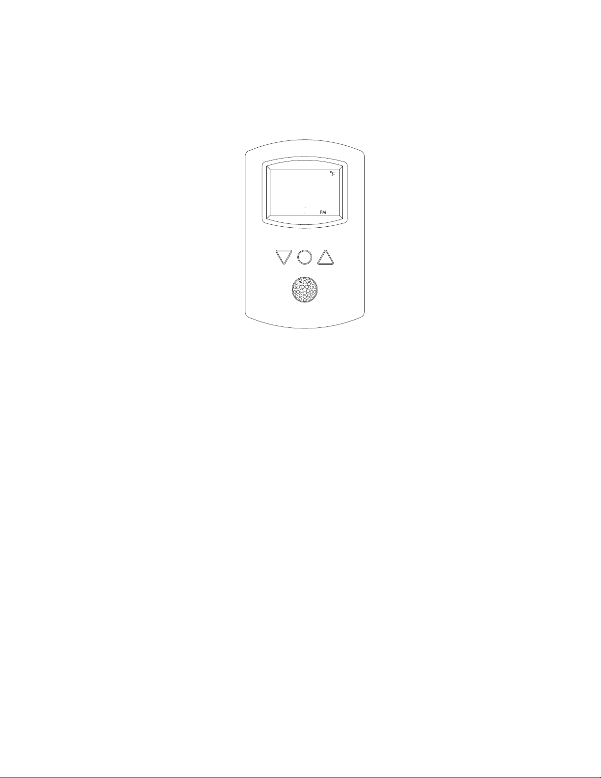
Models STE-8001 and STE-8201 are wall-mounted, temperature sensor for use
with KMC BAC-8000 series VAV controllers. Key features include the following:
◆ Integrated operator interface ready to use with BAC-8000 series VAV
◆ Large LCD display
◆ Simple three-button interface
◆ Continuously displays temperature and time
◆ Separate password protection for user and commissioning functions
◆ Use as a service tool to set up BAC-8000 series VAV controllers
◆ Optional motion sensor to detect space occupancy
controllers
Revision A 3
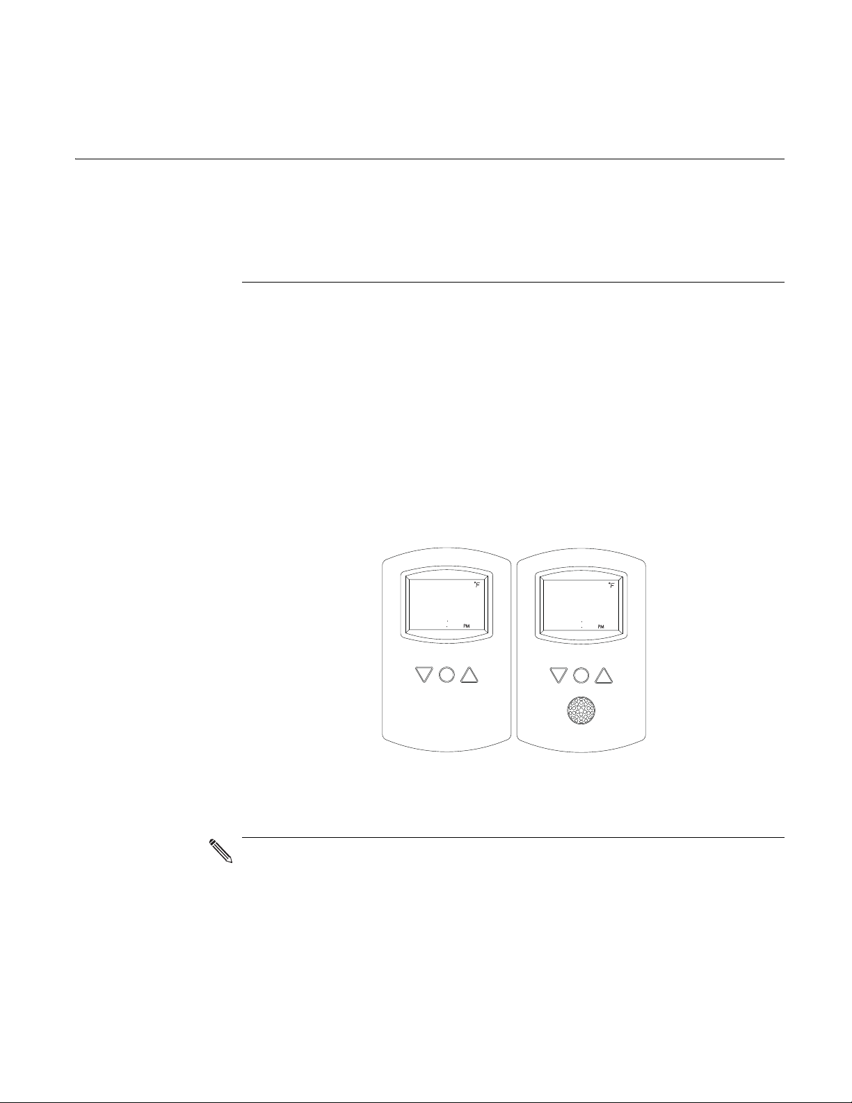
Illustration 1-1 STE-8001 and STE-8201
An STE-8000 series sensor will display time if the controller to which it is
attached has been synchronized with system time within the previous 24
hours.
Page 4

Introduction to STE-8000 sensors
Specifications
Specifications
Display Multifunctional LCD
Compatibility BAC-8000 series VAV controllers
Controller Connection
Connector type Eight-wire RJ-45 modular jack
Cable type and length Standard Ethernet cable up to 75 feet (22.9 meters)
Power Supplied by connected controller
Mounting Surface mount directly to any flat surface or to a
Weight 2.8 ounces (80 grams)
KMC Controls
1.88 x 1.25 in. (48 x 32 mm)
x 4 inch or 4 x 4 inch handy-box. Mounting on a
2
x 4 inch box requires a mounting backplate.
4
Material Flame retardant plastic
Accessories
Mounting backplate HMO-1161W
Gasket HPO-116
Replacement Allen screwsHPO-0044 (package of 10)
Environmental Limits
Operating Temperature 34° to 125° F (1.1 to 51.6° C)
Shipping –40° to 140° F (–40°C to 60° C)
Humidity 0 to 95% relative humidity
non-condensing
4
Revision A
Page 5
STE-8001 and STE-8201 sensors
55
°
10 m
32.8 ft
10 m
32.8 ft
X
0°
10 m
32.8 ft
10 m
32.8 ft
0°
46.5
°
Y
Top view
Side view
7O
12O2
C
B
A
D
E
F
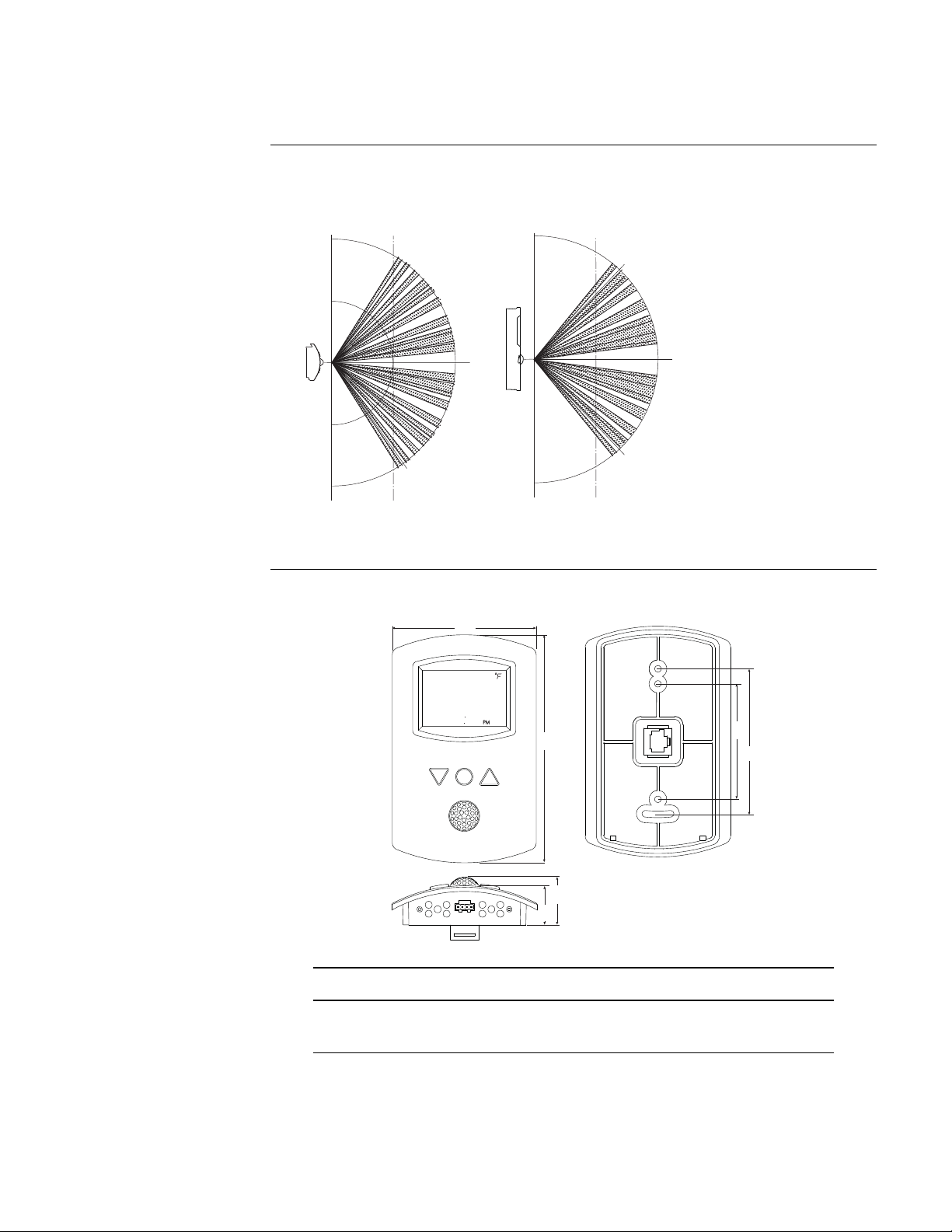
Motion sensor range Model STE-8201 only
Introduction to STE-8000 sensors
Specifications
Detector type Passive infrared
Range 33 feet (10 meters). See diagrams
Dimensions
ABCDE F
3.25 in. 5.16 in. 2.58 in. 3.25 in. 0.87 in. 1.07 in.
83 mm 116 mm 66 mm 83 mm 22 mm 27 mm
Revision A
5
Page 6
Introduction to STE-8000 sensors
Danger
Warning
Caution
Note
Detail
Safety considerations
Models
Safety
considerations
KMC Controls assumes the responsibility for providing you a safe product and
safety guidelines during its use. Safety means protection to all individuals who
install, operate, and service the equipment as well as protection of the
equipment itself. To promote safety, we use hazard alert labeling in this manual.
Follow the associated guidelines to avoid hazards.
Danger represents the most severe hazard alert. Bodily harm or death will
occur if danger guidelines are not followed.
KMC Controls
Temperature sensor only STE-8001
Temperature and motion STE-8201
Warning represents hazards that could result in severe injury or death.
Caution indicates potential personal injury or equipment or property damage
if instructions are not followed.
Notes provide additional information that is important.
Provides programing tips and shortcuts that may save time.
6
Revision A
Page 7

SECTION 2
Installing STE-8000 sensors
Installing the sensors includes the following topics that are covered in this
section.
Planning for motion sensing
For STE-8201 only—Mount the STE-8201 sensor on a wall that will have an
unobstructed view of the typical traffic in the coverage area. When choosing a
location, do not install the sensor in the following areas.
This section provides important instructions and guidelines for
installing the STE-8000 series sensors. Carefully review this
information before installing the controllers.
◆ Planning for motion sensing on page 7
◆ Rough-in preparation on page 8
◆ Installing the sensors on page 8
◆ Maintenance on page 9
◆ Behind curtains or other obstructions
◆ In locations that will expose it to sunlight or heat sources
◆ Near a heating/cooling duct.
For details on the coverage pattern, see Specifications
on page 4.
Illustration 2-1 Typical motion sensing coverage area
The effective detection range is approximately 10 meters or 33 feet. Factors that
may reduce the range include:
◆ The difference between the surface temperature of the object and the
background temperature of the room is too small.
◆ Object movement in a direct line toward the sensor.
◆ Very slow or very fast object movement.
◆ Obstructions as shown in the illustration Typical motion sensing coverage area
on page 7.
Revision A 7
Page 8
Installing STE-8000 sensors
Connecting cable
Maximum 75 feet
or 22.9 meters
Allen
screws
Mounting
base
Turn clockwise to
remove from base.
Rough-in preparation
Rough-in
KMC Controls
False detections may be triggered by:
◆ The temperature inside the detection range suddenly changes because of
the entry of cold or warm air from an air-conditioning or heating unit.
◆ The sensor being directly exposed to sunlight, an incandescent light, or
other source of far-infrared rays.
◆ Small animal movement.
preparation
Complete rough-in wiring at each sensor location prior to sensor installation.
This includes the following.
◆ Routing the connecting cable from the sensor to a controller.
◆ If required, install the appropriate backplate. See Accessories on page 4 for
model numbers.
Connect the STE-8000 series sensor to a controller with a standard Ethernet cable
with RJ-45 connectors on each end. Maximum cable length is 75 feet (22.9
meters). Plenum-rated preassembled cables are recommended.
Installing the sensors
8
To install the sensor on a backplate, do the following:
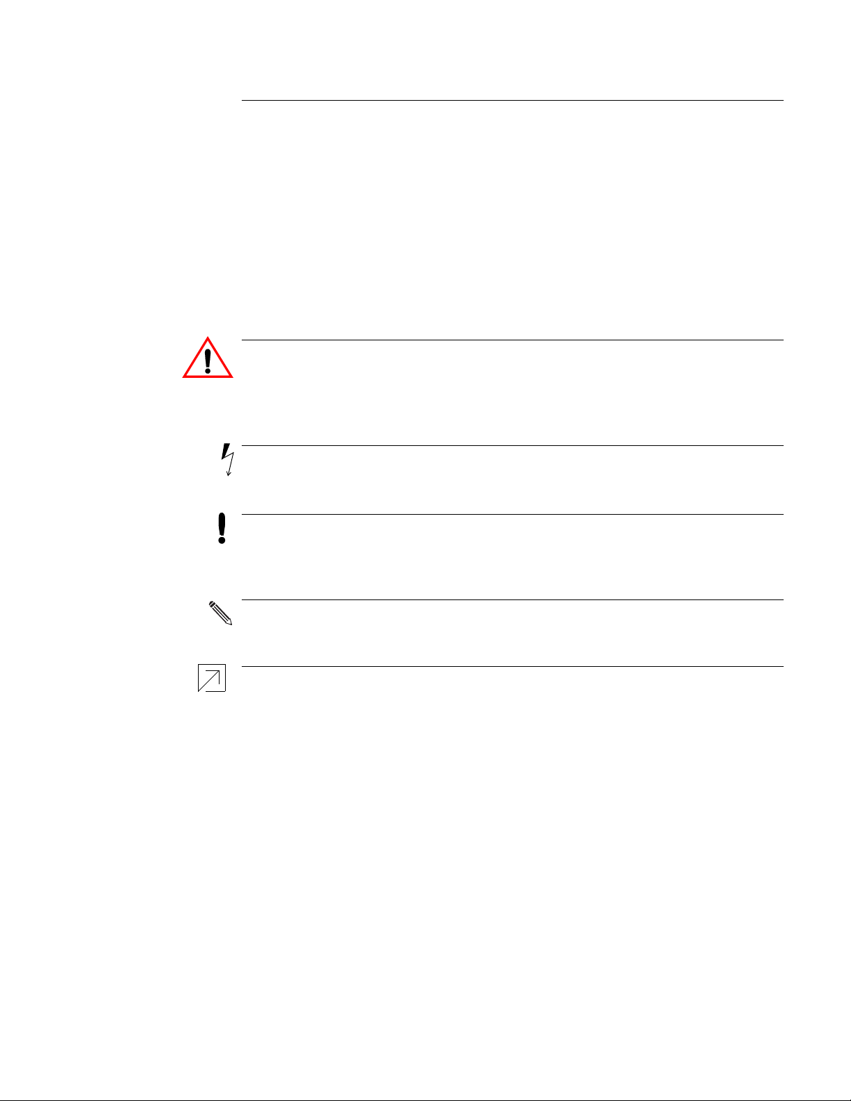
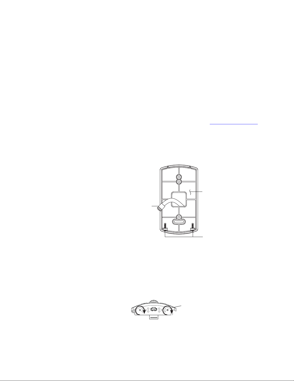
Illustration 2-2 Sensor mounting details
1. Turn the Allen screws in the base of the NetSensor clockwise until they
clear the cover. Swing the sensor away from the mounting base to remove
it.
2. Route the Ethernet cable through the mounting base.
Illustration 2-3 Mounting screws
3. Fasten the mounting base directly to a 2 x 4 inch outlet box or a backplate
with the Allen screws toward the floor.
Revision A
Page 9

STE-8001 and STE-8201 sensors
Installing STE-8000 sensors
Maintenance
4. Insert the Ethernet cable coming from the base into the sensor.
5. Place the top of the sensor over the top of the mounting base and swing it
down over the Allen screw brackets. Be careful not to pinch any wiring.
6. Back the Allen screws out of the brackets until they engage the sensor cover
and hold it in place.
Maintenance Remove dust as necessary from holes in top and bottom. Clean the display with
soft, damp cloth and mild soap.
Revision A
9
Page 10

Installing STE-8000 sensors
Maintenance
KMC Controls
10
Revision A
Page 11
SECTION 3
Note
Set
Point
Set
Point
7O
12O2
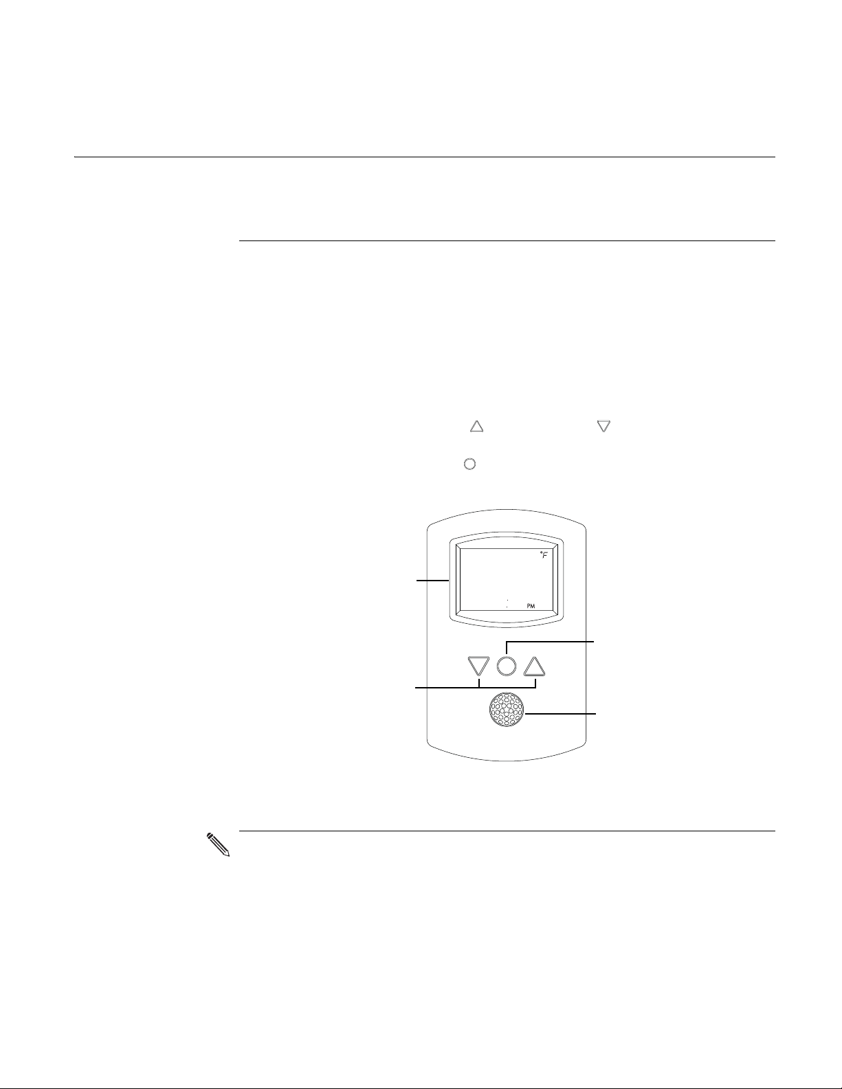
LCD display with
temperature and time
UP and down
buttons
Setpoint button
Motion sensor
(STE-8201 only)
User functions
User functions are limited to changing the occupied temperature setpoints from
the STE-8000.
Operating the STE-8000
The functions are accessible through an STE-8000 series sensor. The functions are
entered or changed using the buttons and display on the front of the STE-8000.
This section covers topics for the end user in a facility.
◆ Pressing either the up button or down button changes a selection,
setting, or value.
◆ Pressing the setpoint button saves the setting or value. Typically saving
an entry also advances to the next display.
Revision A 11
Illustration 3-1 The STE-8000 series display and buttons
An STE-8000 series sensor will display time if the controller to which it is
attached has been synchronized with system time within the previous 24
hours.
Page 12

User functions
72
12S1
Set
Point
Set
Point
PSW1
OOOO
Set
Point
7SO
COOLING
Set
Point
68O
HEATING
Changing setpoints
Changing
KMC Controls
setpoints
Enter occupied setpoints
To enter or change the occupied setpoints you will need a Level 1 password.
Procedure Steps STE display
Starting display
Enter the level one
password
Start from the temperature display.
1. Press the button.
2. Press the or buttons to change
the first digit.
3. Press the button to select the next
digit. Repeat for all four digits.
4.
Note: If a Level 1 password has not
previously been entered, the display
will change to the occupied cooling
setpoint display after Step 1.
Set the occupied
cooling setpoint
1. Press the or buttons to change
the cooling setpoint temperature. The
setpoint changes in increments of 0.5
degrees.
2. Press the button to save the value.
The display advances to set the
heating setpoint.
Set the occupied
heating setpoint
1. Press the or buttons to change
the heating setpoint temperature.
The setpoint changes in increments
of 0.5 degrees.
2. Press the button to save the value.
The display returns to the
temperature display.
12
Revision A
Page 13

SECTION 4
Note
Commissioning functions
This topics in this section are advanced topics for control technicians
and engineers.
The commissioning functions that are accessible through an STE-8000 series
sensor are values and settings that are entered during the installation and
commissioning of a VAV terminal unit. Typically these functions do not change
after the installation and commissioning process.
To set up the commissioning functions, you will need the following:
◆ Information about the VAV terminal unit including the configuration for
◆ The installation and operation manual supplied with the controller to
◆ The building automation system plans.
fans and reheat
which the STE-8000 series sensor is connected.
Users may change the occupied heating and cooling setpoints without accessing
the commissioning functions. This procedure is covered in
page 11.
The instructions for commissioning functions cover all of the functions that an
STE-8000 sensor can set up in the BAC-8000 series of controllers. Not all
functions are available on every model of controller. Consult the installation
and operation manual supplied with the controller to verify the functions and
options that are available.
User functions on
Revision A 13
Page 14

Commissioning functions
72
12S1
Set
Point
Set
Point
PSW2
OOOO
COMM
The commissioning sequence
The
commissioning
KMC Controls
sequence
Enter the commissioning mode
Enter the commissioning mode
Procedure Steps STE display
Starting display Start from the temperature display.
Set the commission functions in the following sequence.
1. Enter the commissioning mode on page 14
2. Setting up network communications on page 15
3. Box options on page 16
4. Setting commissioning setpoints on page 20
5. Setting the airflow setpoints on page 23
6. Balancing airflow on page 27
For access to the commissioning functions you will need a Level 2 password.
◆ If the controller has not been previously set up, no password is required.
◆ A new Level 2 password can be entered in the advanced commissioning
functions. See the topic Advanced options
on page 31.
Enter the
commissioning
password
Select a
commissioning
function
1. Press the and buttons together
and hold them down until the
display changes to PSW2.
2. Press the or button to change
the first digit.
3. Press the button to select the next
digit. Repeat for all four digits.
4. When the button is pushed for the
fourth correct digit, the display
changes to COMM.
Note: If a Level 2 password has not
previously been entered the display
will change to the COMM display after
Step 1.
Access to the commissioning
functions always start at the COMM
display.
14
Revision A
Page 15

STE-8001 and STE-8201 sensors
72
12S1
PSW2
OOOO
Set
Point
COMM
Set
Point
Set
Point
D ID
OO72O69
Set
Point
MAC
11
Set
Point
BAUD
384OO
Set
Point
COMM
Setting up
network
Commissioning functions
Setting up network communications
communications
Procedure to set up network communications
Procedure Steps STE display
Starting display 1. Start at the temperature display.
Select the COMM
display
Set the network communication settings before placing a controller on the
network. Setting network settings requires entering the Level 2 password which
is described in the topic Enter the commissioning mode
on page 14.
2. Enter the Level 2 password. The
display changes to the COMM.
Press the button. The display changes
to DI D.
Enter the device
instance.
Enter the MAC
address.
Enter the baud
Advance or exit
1. Press the or buttons to change
the first digit.
2. Press the button to select the next
digit. Repeat for all seven digits.
3. When the button is pressed for the
last digit, the display changes to MAC.
1. Press the or buttons to change
the MAC address.
2. Press the button to save the
selected MAC address.
The display changes to BAUD.
1. Press the or buttons to select a
new baud.
2. Press the button is save the
selected baud.
The display returns to COMM.
1. Press the or buttons to select
one of the following:
• BLNC or CNFG options
• EXIT to return to the temperature
display.
2. Press the button to select the next
function.
Revision A
15
Page 16

Commissioning functions
72
12S1
PSW2
OOOO
Set
Point
Set
Point
COMM
CNFG
STPT
BOX
Set
Point
9O4
PKFT
Set
Point
9O4
SKFT
Box options
KMC Controls
Box options The box options set up the controller for the specific mechanical installation of
the VAV terminal unit. Setting the box options requires entering the Level 2
password which is described in the topic Enter the commissioning mode
page 14.
Procedure to set the box functions
Procedure Steps STE display
Starting display 1. Start at the temperature display.
2. Enter the Level 2 password. The
display changes to the COMM.
on
Select the box
settings display.
Set the primary
VAV te r m i na l u n it
K-factor.
1. From the COMM display, press the
or buttons to show the CNFG
display.
2. Press the button to select the CNFG
options. The display changes to
STPT.
3. Press the or buttons to change
the display to BOX.
4. Press the button to select BOX.
1. Press the or buttons to set the
primary K-factor.
2. Press the button to save the entry
and advance to the next function.
16
Set the secondary
VAV te r m i na l u n it
K-factor.
1. Press the or buttons to set the
secondary K-factor.
2. Press the button to save the entry
and advance to the next function.
Revision A
Page 17

STE-8001 and STE-8201 sensors
Set
Point
NONE
REHT
Set
Point
NONE
FAN
Procedure to set the box functions (Continued)
Procedure Steps STE display
Commissioning functions
Box options
Set the mode of
reheat for the
terminal unit
Set the fan option
1. Press the or buttons to choose
one of the following reheat options.
None—Reheat is not enabled.
Staged—Enables two or three stage
reheat. If lighting is enabled the
staged reheat is set to two stages. If
lighting is not enabled, three reheat
stages are available.
Modulating—The reheat output
varies from 0-10 volts.
Floating—The reheat outputs control
a tristate actuator.
Time proportional—Controls a
thermal wax valve with a 24-volt
triac output.
2. Press the button to save the reheat
option and advance to the next
function.
1. Press the or buttons to choose
one of the following fan options.
None—No fan is connected to the
controller.
Series—The VAV unit includes a
series fan.
Parallel—The VAV unit includes a
parallel fan.
2. Press the button to save the fan
option and advance to the next
function.
Revision A
17
Page 18

Commissioning functions
Set
Point
CCW
DDIR
Set
Point
VAV
DUAL
Box options
Procedure to set the box functions (Continued)
Procedure Steps STE display
KMC Controls
Set the damper
direction to close
Set the dual duct
mode
1. Press the or buttons to which
direction to damper moves to close.
CCW—The actuator turns
counterclockwise to close the
damper.
CW—The actuator turns clockwise to
close the damper.
2. Press the button to save the
damper option and advance to the
next function.
1. Press the or buttons to choose
the dual duct mode of operation.
VAV—The system maintains space
temperature with variable air volume
control.
CAC—The system maintains space
temperature with constant air
volume control.
Supply exhaust offset—The system
maintains space temperature with
the primary VAV controller. The
secondary controller controls the
exhaust unit. Supply/exhaust
tracking is controlled as an offset
percentage.
Supply exhaust differential—The
system mantains space temperature
with the primary VAV controller. The
secondary controller controls the
exhaust unit. Supply/exhaust
tracking controlled by differential
pressure.
Indoor air quality—Room
temperature is maintained with
primary VAV unit and CO2 levels
controlled by secondary VAV unit.
2. Press the button to save the dual
duct option and advance to the next
function.
18
Revision A
Page 19

STE-8001 and STE-8201 sensors
Set
Point
BOX
Procedure to set the box functions (Continued)
Procedure Steps STE display
Commissioning functions
Box options
Advance or exit
1. Press the or buttons to select
one of the following:
• STPT, FLOW, or ADVC options
• BACK to choose another
commissioning function
• EXIT to return to the temperature
display.
2. Press the button to select the next
function.
Revision A
19
Page 20

Commissioning functions
PSW2
OOOO
Set
Point
Set
Point
COMM
CNFG
STPT
Set
Point
MIN
68O
Set
Point
MAX
78O
Setting commissioning setpoints
Setting
commissioning
KMC Controls
setpoints
Procedure to set the commissioning setpoints
The commissioning setpoints set the operational parameters and limits for the
VAV terminal unit. Setting configuration setpoints requires entering a Level 2
password which is described in the topic Enter the commissioning mode
page 14.
Procedure Steps STE display
Starting display
Select the setpoint
display.
Enter the Level 2 password. The display
changes to the COMM.
1. From the COMM display, press the
or buttons to show the CNFG
display.
2. Press the button to select the CNFG
options. The display changes to
STPT.
on
Set the minimum
cooling setpoint
Set the maximum
heating setpoint
3. Press the button to select the STPT
options.
1. Press the or buttons to set the
minimum cooling setpoint. The
setpoint will change in 0.5°
increments.
2. Press the button to save the
setpoint and advance to the next
function.
1. Press the or buttons to set the
maximum heating setpoint. The
setpoint will change in 0.5°
increments.
2. Press the button to save the
setpoint and advance to the next
function.
20
Revision A
Page 21

STE-8001 and STE-8201 sensors
Set
Point
OCCL
74O
Set
Point
OCHT
7OO
Set
Point
UNCL
8OO
Set
Point
UNHT
62O
Set
Point
74
CHNG
Procedure to set the commissioning setpoints (Continued)
Procedure Steps STE display
Commissioning functions
Setting commissioning setpoints
Set the occupied
cooling setpoint
Set the occupied
heating setpoint
Set the unoccupied
cooling setpoint
Set the unoccupied
heating setpoint
Set the supply air
temperature
changeover setpoint
1. Press the or buttons to set the
occupied cooling setpoint. The
setpoint will change in 0.5°
increments.
2. Press the button to save the
setpoint and advance to the next
function.
Note: This setpoint can also be changed as
described in the section
User functions on
page 11.
1. Press the or buttons to set the
occupied heating setpoint. The
setpoint will change in 0.5°
increments.
2. Press the button to save the
setpoint and advance to the next
function.
Note: This setpoint can also be changed as
described in the section
User functions on
page 11.
1. Press the or buttons to set the
unoccupied cooling setpoint. The
setpoint will change in 0.5°
increments.
2. Press the button to save the
setpoint and advance to the next
function.
1. Press the or buttons to set the
unoccupied heating setpoint. The
setpoint will change in 0.5°
increments.
2. Press the button to save the
setpoint and advance to the next
function.
1. Press the or buttons to set the
changeover setpoint. The setpoint
will change in 1° increments.
2. Press the button to save the
setpoint and advance to the next
function.
Revision A
21
Page 22

Commissioning functions
Set
Point
O5
DIFF
Set
Point
OS
Set
Point
OO
DDOF
Set
Point
OO5
DDDP
Set
Point
1OOO
C2SP
Set
Point
STPT
Setting commissioning setpoints
Procedure to set the commissioning setpoints (Continued)
Procedure Steps STE display
KMC Controls
Set the minimum
temperature
differential
setpoint
Set the standby
differential
setpoint
Set the supply
exhaust offset
Set the supply
exhaust differential
pressure setpoint
1. Press the or buttons to set the
differential setpoint. The setpoint
will change in 1° increments.
2. Press the button to save the
setpoint and advance to the next
function.
1. Press the or buttons to set the
standby differential setpoint. The
setpoint will change in 1° increments.
2. Press the button to save the
setpoint and advance to the next
function.
1. Press the or buttons to set the
supply exhaust offset setpoint. The
setpoint will change in 1%
increments.
2. Press the button to save the
setpoint and advance to the next
function.
1. Press the or buttons to set the
supply exhaust differential pressure
setpoint.The setpoint will change in
increments of 0.01 inches of water.
2. Press the button to save the
setpoint and advance to the next
function.
22
Set the CO2
setpoint.
Advance or exit
1. Press the or buttons to change
CO2 setpoint. The setpoint changes
increments for 1 part per million.
2. Press the button to save the
setpoint and complete the setpoint
changes.
The display returns to STPT.
1. Press the or buttons to select
one of the following:
• FLOW, BOX, or ADVC options
• BACK to choose another
commissioning function
• EXIT to return to the temperature
display.
2. Press the button to select the next
function.
Revision A
Page 23

STE-8001 and STE-8201 sensors
Note
72
12S1
PSW2
OOOO
Set
Point
Set
Point
COMM
CNFG
STPT
FLOW
Setting the
Commissioning functions
Setting the airflow setpoints
airflow setpoints
Procedure to set the airflow setpoints
Procedure Steps STE display
Starting display 1. Start at the temperature display.
The airflow setpoints configure the airflow limits for the VAV terminal unit.
Setting the airflow setpoints requires entering a Level 2 password which is
described in the topic
If the VAV unit is a heat only or cooling only unit, the airflow setpoints for the
unused mode must be set within the range of the mode in use. Failure to set the
unused setpoints correctly will result in unpredictable or erroneous air
balancing settings.
2. Enter the Level 2 password. The
display changes to the COMM.
Enter the commissioning mode on page 14.
Select the flow
setpoint display.
1. From the COMM display, press the
or buttons to show the CNFG
display.
2. Press the button to select the CNFG
options. The display changes to
STPT.
3. Press the or buttons to change
the display to FLOW.
4. Press the button to select FLOW.
Revision A
23
Page 24

Commissioning functions
Set
Point
O O
MNCL
Set
Point
3SO
MXCL
Set
Point
OO
MNHT
Set
Point
3SO
MXHT
Set
Point
2O
MIN
Set
Point
1OO
MAX
Setting the airflow setpoints
Procedure to set the airflow setpoints (Continued)
Procedure Steps STE display
KMC Controls
Set the cooling
minimum airflow
limit
Set the cooling
maximum airflow
limit
Set the heating
minimum airflow
limit
Set the heating
maximum airflow
limit
Set the minimum
limit for fan speed
Set the maximum
limit for fan speed
1. Press the or buttons to set the
minimum limit for cooling airflow.
The setpoint will change in 1 CFM
increments.
2. Press the button to save the
setpoint and advance to the next
function.
1. Press the or buttons to set the
maximum limit for cooling airflow.
The setpoint will change in 1 CFM
increments.
2. Press the button to save the
setpoint and advance to the next
function.
1. Press the or buttons to set the
minimum limit for heating airflow.
The setpoint will change in 1 CFM
increments.
2. Press the button to save the
setpoint and advance to the next
function.
1. Press the or buttons to set the
maximum limit for heating airflow.
The setpoint will change in 1 CFM
increments.
2. Press the button to save the
setpoint and advance to the next
function.
1. Press the or buttons to set the
minimum limit for the fan speed. The
setpoint will change in 1%
increments.
2. Press the button to save the
setpoint and advance to the next
function.
1. Press the or buttons to set the
maximum limit for the fan speed.
The setpoint will change in 1%
increments.
2. Press the button to save the
setpoint and advance to the next
function.
24
Revision A
Page 25

STE-8001 and STE-8201 sensors
Set
Point
O O
MNCL
Set
Point
3SO
MXCL
Set
Point
OO
MNHT
Set
Point
3SO
MXHT
Set
Point
2O
MIN
Set
Point
1OO
MAX
Procedure to set the airflow setpoints (Continued)
Procedure Steps STE display
Commissioning functions
Setting the airflow setpoints
Set the cooling
minimum airflow
limit
Set the cooling
maximum airflow
limit
Set the heating
minimum airflow
limit
Set the heating
maximum airflow
limit
Set the minimum
limit for fan speed
Set the maximum
limit for fan speed
1. Press the or buttons to set the
minimum limit for cooling airflow.
The setpoint will change in 1 CFM
increments.
2. Press the button to save the
setpoint and advance to the next
function.
1. Press the or buttons to set the
maximum limit for cooling airflow.
The setpoint will change in 1 CFM
increments.
2. Press the button to save the
setpoint and advance to the next
function.
1. Press the or buttons to set the
minimum limit for heating airflow.
The setpoint will change in 1 CFM
increments.
2. Press the button to save the
setpoint and advance to the next
function.
1. Press the or buttons to set the
maximum limit for heating airflow.
The setpoint will change in 1 CFM
increments.
2. Press the button to save the
setpoint and advance to the next
function.
1. Press the or buttons to set the
minimum limit for the fan speed. The
setpoint will change in 1%
increments.
2. Press the button to save the
setpoint and advance to the next
function.
1. Press the or buttons to set the
maximum limit for the fan speed.
The setpoint will change in 1%
increments.
2. Press the button to save the
setpoint and advance to the next
function.
Revision A
25
Page 26

Commissioning functions
Set
Point
OO
MNC2
Set
Point
3SO
MXC2
Set
Point
FLOW
Setting the airflow setpoints
Procedure to set the airflow setpoints (Continued)
Procedure Steps STE display
KMC Controls
Set the minimum
limit for indoor air
quality ventilation
Set the maximum
limit for indoor air
quality ventilation
Advance or exit
1. Press the or buttons to set the
minimum limit for ventilation
airflow. The setpoint will change in 1
CFM increments.
2. Press the button to save the
setpoint and advance to the next
function.
1. Press the or buttons to set the
maximum limit for ventilation
airflow. The setpoint will change in
1 CFM increments.
2. Press the button to save the
setpoint and advance to the next
function.
1. Press the or buttons to select
one of the following:
• STPT, BOX, or ADVC options
• BACK to choose another
commissioning function
• EXIT to return to the temperature
display.
2. Press the button to select the next
function.
26
Revision A
Page 27

STE-8001 and STE-8201 sensors
Note
Note
72
12S1
PSW2
OOOO
Set
Point
Set
Point
COMM
BLNC
PRI
Commissioning functions
Balancing airflow
Balancing airflow The airflow balancing method described in this section requires a flow hood or
other accurate method to measure airflow. The airflow balancing procedure
requires entering the Level 2 password which is described in the topic
commissioning mode on page 14.
If the VAV unit is a heat only or cooling only unit, the airflow setpoints for the
unused mode must be set within the range of the mode in use. Failure to set the
unused setpoints correctly will result in unpredictable or erroneous air
balancing settings. See Setting the airflow setpoints
to adjust the setpoints.
Starting the balancing procedure erases all previous airflow correction factors.
The airflow readings displayed by the STE-8000 are the actual uncorrected
airflow readings as measured by the controller.
on page 23 for the procedure
Enter the
The airflow balancing procedure
Procedure Steps STE display
Starting display 1. Start at the temperature display.
2. Enter the Level 2 password. The
display changes to the COMM.
Select the COMM
display
1. From the COMM display, press the
or buttons to show the BLNC
display.
2. Press the button to select BLNC.
The display advances to PRI.
Revision A
3. Press the button to select PRI.
27
Page 28

Commissioning functions
Set
Point
Set
Point
PMAX
OO
Set
Point
Set
Point
PMIN
OO
Balancing airflow
The airflow balancing procedure (Continued)
Procedure Steps STE display
KMC Controls
Measure and enter
the actual
maximum primary
airflow
Measure and enter
the actual
minimum primary
airflow
The display begins flashing PMAX
and also displays the actual airflow
at the bottom.
Note: The airflow will attempt to stabilize
on the highest value for either the cooling
or heating maximum airflow even if only
one mode is operational.
Note: The airflow displayed by the
STE-8000 in this step is the actual,
uncorrected airflow.
1. Wait for the maximum airflow value
to stabilize.
2. With a flow hood, measure the actual
airflow.
3. Press the button to advance to the
entry display. PMAX stops flashing.
4. Press the or buttons to enter the
measured airflow.
5. Press the button to save the
measured airflow. The display
changes to PMIN.
The display begins flashing PMIN
and also displays the actual airflow
at the bottom.
Note: The airflow will attempt to stabilize
on the lowest value for either the cooling
or heating minimum airflow even if only
one mode is operational.
28
Note: The airflow displayed by the
STE-8000 in this step is the actual,
uncorrected airflow.
1. Wait for the minimum airflow value
to stabilize.
2. With a flow hood, measure the actual
airflow.
3. Press the button to advance to the
entry display. PMIN stops flashing.
4. Press the or buttons to enter the
measured airflow.
5. Press the button to save the
measured airflow. The display
advances to PRI.
Revision A
Page 29

STE-8001 and STE-8201 sensors
Set
Point
PRI
SEC
Set
Point
Set
Point
SMAX
OO
The airflow balancing procedure (Continued)
Procedure Steps STE display
Commissioning functions
Balancing airflow
Advance or exit
Measure and enter
the actual
maximum
secondary airflow
1. Press the or buttons to select
one of the following:
• SEC to balance the secondary VAV
for dual duct systems
• BACK to choose another
commissioning function
• EXIT to return to the temperature
display.
2. Press the button to select the next
function.
The display begins flashing SMAX
and also displays the actual airflow
at the bottom.
Note: The airflow displayed by the
STE-8000 in this step is the actual,
uncorrected airflow.
1. Wait for the maximum airflow value
to stabilize.
2. With a flow hood, measure the actual
airflow.
3. Press the button to advance to the
entry display. SMAX stops flashing.
4. Press the or buttons to enter the
measured airflow.
5. Press the button to save the
measured airflow. The display
advances to SMIN.
Revision A
29
Page 30

Commissioning functions
Set
Point
Set
Point
SMIN
OO
Set
Point
SEC
Balancing airflow
The airflow balancing procedure (Continued)
Procedure Steps STE display
KMC Controls
Measure and enter
the actual
minimum
secondary airflow
Advance or exit
The display begins flashing SMIN
and also displays the actual airflow
at the bottom.
Note: The airflow displayed by the
STE-8000 in this step is the actual,
uncorrected airflow.
1. Wait for the minimum airflow value
to stabilize.
2. With a flow hood, measure the actual
airflow.
3. Press the button to advance to the
entry display. SMIN stops flashing.
4. Press the or buttons to enter the
measured airflow.
5. Press the button to save the
measured airflow. The display
advances to SEC.
1. Press the or buttons to select
one of the following
• PRI to balance the primary VAV
for dual duct systems
• BACK to choose another
commissioning function
• EXIT to return to the temperature
display.
2. Press the button to select the next
function.
30
Revision A
Page 31

STE-8001 and STE-8201 sensors
72
12S1
PSW2
OOOO
Set
Point
Set
Point
COMM
CNFG
STPT
ADVC
Set
Point
Set
Point
PSW1
OOOO
Commissioning functions
Advanced options
Advanced
options The advanced options set up passwords and special features in the controller.
Setting the advance options requires entering the Level 2 password which is
described in the topic Enter the commissioning mode
Procedure to set the advanced options
Procedure Steps STE display
Starting display 1. Start at the temperature display.
2. Enter the Level 2 password. The
display changes to the COMM.
on page 14.
Select the
advanced display.
Enter a new
Level
1 password
1. From the COMM display, press the
or buttons to show the CNFG
display.
2. Press the button to select the CNFG
options. The display changes to
STPT.
3. Press the or buttons to change
the display to ADVC.
4. Press the button to select ADVC.
Note: Entering four zeros (0000) removes
the password.
Revision A
1. Press the or buttons to change
the first digit.
2. Press the button to select the next
digit. Repeat for all four digits.
3. When the button is pressed for the
last digit, the new password is saved
and the display advances.
31
Page 32

Commissioning functions
Set
Point
Set
Point
PSW2
OOOO
Set
Point
3O
OVRD
Set
Point
15
Set
Point
DISABLE
DAT
Set
Point
OO
CALIB
Advanced options
Procedure to set the advanced options (Continued)
Procedure Steps STE display
KMC Controls
Enter a new
2 password
Level
password
Set the local
unoccupied
override timer
Set the standby
time
Note: Entering four zeros (0000) removes
the password.
1. Press the or buttons to change
the first digit.
2. Press the button to select the next
digit. Repeat for all four digits.
3. When the button is pressed for the
last digit, the new password is saved
and the display advances.
Note: This function applies only to
controllers that will use an STE-6017
sensor.
1. Press the or buttons to set the
local unoccupied override timer. The
value will change in 1 minute
increments.
2. Press the button to save the
setpoint and advance to the next
function.
Note: This function applies only to
controllers that will use an STE-8201
sensor.
Set discharge air
temperature
limiting
Set the STE-8000
temperature sensor
calibration
constant
3. Press the or buttons to set the
time for the standby time. The value
will change in 1 minute increments.
4. Press the button to save the
setpoint and advance to the next
function.
1. Press the or buttons to enable or
disable discharge air temperature
limiting.
2. Press the button to save the
setpoint and advance to the next
function.
1. Press the or buttons to set the
calibration constant. The setpoint
will change in 0.1 minute increments.
2. Press the button to save the
setpoint and advance to the next
function.
32
Revision A
Page 33

STE-8001 and STE-8201 sensors
Set
Point
ADVC
Procedure to set the advanced options (Continued)
Procedure Steps STE display
Commissioning functions
Advanced options
Advance or exit
1. Press the or buttons to select
one of the following:
• STPT, FLOW, or BOX options
• BACK to choose another
commissioning function
• EXIT to return to the temperature
display.
Press the button to select the next
function.
Revision A
33
Page 34

Commissioning functions
Advanced options
KMC Controls
34
Revision A
 Loading...