

Page 1
Installation Manual
Single Duct VAV Terminals
SD-IOM-1.0 6-15-02
Receiving Inspection
After unpacking the terminal, check it for
shipping damage. If any shipping
damage is found, report it immediately
to the delivering carrier. Store units in a
clean, dry location prior to installation.
Caution: Do not use the ow sensor,
connecting tubing, or damper shaft
linkage as a handle to lift o r mo ve
assembly. D amage to the ow
sensor or controls may result.
Supporting the Assembly
Many basic single duct terminals are
light enough to be supported by the duct
work itself. Where heavier access ory
modules, such as DDC controls, coils,
attenuators, or multiple outlets are
included, the terminal should be
supported directly. Straps screwe d
directly into the side of the terminal,
threaded rod through the opti onal
hanger brackets (see Figure 1), or the
method prescribed for the rect angular
duct on the job specications m ay be
used.
Important: If equipped with pneumatic
controls, the terminal must be mounted
right side up. It must be level wi thin
+ or - 10 degrees of hori zon
parallel to the air ow and at the right
angle of air ow. The control side of the
term inal i s l abeled wi th an arrow
indicating UP. The rst let te r of th e
model number (P) indicates pneumatic
controls. Most electronic units (A- analog
controls and D-digital controls) can be
installed in any orientation. Check with
the local TITUS representative for
verication.
tal, both
Duct Connections
Slip each inlet duct over the inlet collar
of the terminal. Fasten and seal the
connection by the method prescri bed by
the job specication.
The diameter o f t he i nl et duct "D " in
inches must be equal to the listed size
of the terminal; e.g. a duct that actually
measures 8 inches must be tted to a
size 8 terminal. The inlet collar of the
terminal is made 1/8 inch smaller than
listed size in order to t inside the duct
(see Figure 1).
Note: Do not insert duct work inside
the inlet collar of the assembly. Inlet
duct should be installed in accordance
with SMACNA guidelines.
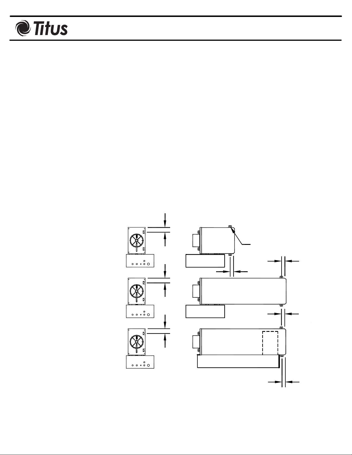
2" TYP
2" TYP
W / ATTENUATOR
2" TYP
W / ELECTRIC HEAT
The outlet end of the terminal is
designed for use with slip and drive duct
connections. A rectangular duct the size
o f the t e r m inal o utlet should be
attached.
If single-point electronic velocity sensor
is used, 3 to 5 inlet duct diameters of
straight duct should be provided at the
terminal inlet; for specic guidelines,
consult the manufacturer’s installation
material. Sensor(s) may be attached to
the inside of control enclosu re fo r
protection during shipping. Sensor must
be i nse rte d in inlet duct of terminal
before operation. R em o ve any
protective plastic devices fr om ti p o f
sensor before installation.
Optional
Hanger Bracket
70738001
1 1/2" TYP
1 1/2" TYP
1 1/2" TYP
Figure 1. Single Duct Recommended Hanger Bracket Locations
1 1/2" TYP
Page 2

SD-IOM-2.0 6-15-02
Field Wiring
All field wiring must comply with the local codes and
with the National Electrical Code (ANSI/NFPA 70-1981).
Electrical, control and piping diagrams are shown on the
exterior labeling or on the diagram on the inside of
control enclosure cover. All electric heaters if provided
by TITUS are balanced by kW per stage. The installing
electrician should rotate these heater stages by phase
in order to help balance the building electric load.
Control Start-up, Operation
Detailed information regarding power, accessory and
communications connections, start-up and operating
procedures for the controls provided by TITUS are
available from your local TITUS representative. For
specific information on controls by other manufacturers,
contact that manufacturer’s local branch or dealer.
Important: Units with digital controllers may incorporate
specific communication addresses based on Building
Management Systems Architecture, and original
engineering drawings. Installing the terminal in a
different location than noted on unit label may result in
excessive start-up labor.
Replacement Parts
Description Part Number
Primary Damper Assembly
Size 4-5-6" 31171301
Size 7" 31171302
Size 8" 31171303
Size 9" 31171304
Size 10" 31171305
Size 12" 31171306
Size 14" 31171307
Size 16" 31171308
Damper Shaft Extension
Short Stub all sizes 70300301
Long Ext. Sz. 4-6, 14, 16 70300302
Long Ext. Sz. 7-12 70300303
Shaft Bearing - All 70324901
Control Tube
Red Stripe 1/4" O.D. 61510035
Green Stripe 1/4" O.D. 61510234
Red Stripe 3/8" O.D. 61510279
Green Stripe 3/8" O.D. 61510280
Yellow Stripe 1/4" O.D. 61510260
White Stripe 1/4" O.D. 61510261
Blue Stripe 1/4" O.D. 61510262
Calibration Instructions
For Pneumatic Controls, see PNEU-IOM: Operations
Manual for Pneumatic Controls.
For Analog Controls: Titus TA1, see ANA-IOM: Analog
Controller Calibration.
For Digital Controls: see control manufacturer's manual
Tees for sensor taps
Plastic 1/4" 42150011
Plastic 3/8" 42150020
Plugs for tees
1/4" 42160081
3/8" 10015601
AeroCrossTM Multipoint Velocity Sensors
Size 4" 3151520001
Size 5" 3151520001
Size 6" 3151520002
Size 7" 3151520003
Size 8" 3151520004
Size 9" 3151520005
Size 10" 3151520006
Size 12" 3151520007
Size 14" 3151520008
Size 16" 3151520009
Size 24" x 16" 3151520009
 Loading...