

Page 1
Installation Manual
IOM-RAB-00 08-15-04
RAB Rooftop Air Handler Belt Drive
Installation, Operation, and Maintenance Manual
Contents Page
Introduction.............................................................1
General ....................................................................1
Safety .......................................................................1
Inspection................................................................1
Product Description ............................................... 1
Model Number Specification .............................................1
Unit Cabinet Dimensions...................................................2
Service Data......................................................................2
Shipping Weight ................................................................2
Installation...............................................................3
Ductwork ...........................................................................3
Duct Insulation and Vapor Proofing................................... 4
Sound Attenuation............................................................. 4
Condensate Drain .............................................................4
Water Piping......................................................................4
Motors and Drives .............................................................4
Electrical Connections....................................................... 4
Installation of Options............................................5
Manual Air Damper ...........................................................5
Motorized Air Damper .......................................................6
Roof Curbs ........................................................................ 8
Air Handler Startup................................................. 9
Operation and Maintenance ..................................9
Return Air Filters ...............................................................9
Coil ....................................................................................9
Belt and Pulley ..................................................................9
Motor ................................................................................. 9
Blower ...............................................................................9
Abbreviations........................................................ 10
This guide does NOT supersede or circumvent any
applicable national, state, or local codes.
The installation is to be performed only by individuals
whose experience meets or exceeds the requirements of
the work involved.
The installer must read the entire contents of this guide
and develop a thorough understanding before beginning
installation.
Due to a continuing program of product research, Titus
reserves
any or all specifications or designs without incurring
obligations.
the right to discontinue or change without notice,
Safety
The installation and/or servicing of comfort conditioning
equipment can be hazardous due to system pressures
and electrical devices.
Caution: Only trained/qualified personnel should
perform service and/or installation.
Observe all precautions and warnings in product
data or attached to the unit.
Follow all safety codes. Wear eye protection and gloves.
Have a fire extinguisher readily available.
Caution: Disconnect all power supplies before
accessing equipment.
Disconnecting more than one power supply may
be required to de-en
ELECTRIC SHOCK CAN CAUSE DEATH.
ergize some equipment.
DANGER
Inspection
Introduction
This document provides installation, operation, and
maintenance information for the Titus Rooftop Air Handler
Belt Drive (RAB) models.
Additional information may be found at the Titus website,
www.titus-hva
c.com.
General
The following information is to be used by the installer as a
guide. Since each installation is unique unto itself, only
general topics are covered. Topic order may not be the
same as required by actual installation.
605 Shiloh Road • Plano, Texas 75074 • 972- 212-4800
All rights reserved. No part of this work may be reproduced or transmitted in any form or any means, electronic or mechanical, including photocopying and recording, or by any information storage retrieval system without permission in writing from Air Distribution Technologies.
Thoroughly inspect all packages upon receipt. Ensure
carton(s) have not been dropped, crushed or punctured.
Inspect all contents for damage. If damage is found,
immediately file a claim with the delivering carrier.
Product Description
This section provides model features, number
nomenclature, various unit dimensions, and shipping
weights.
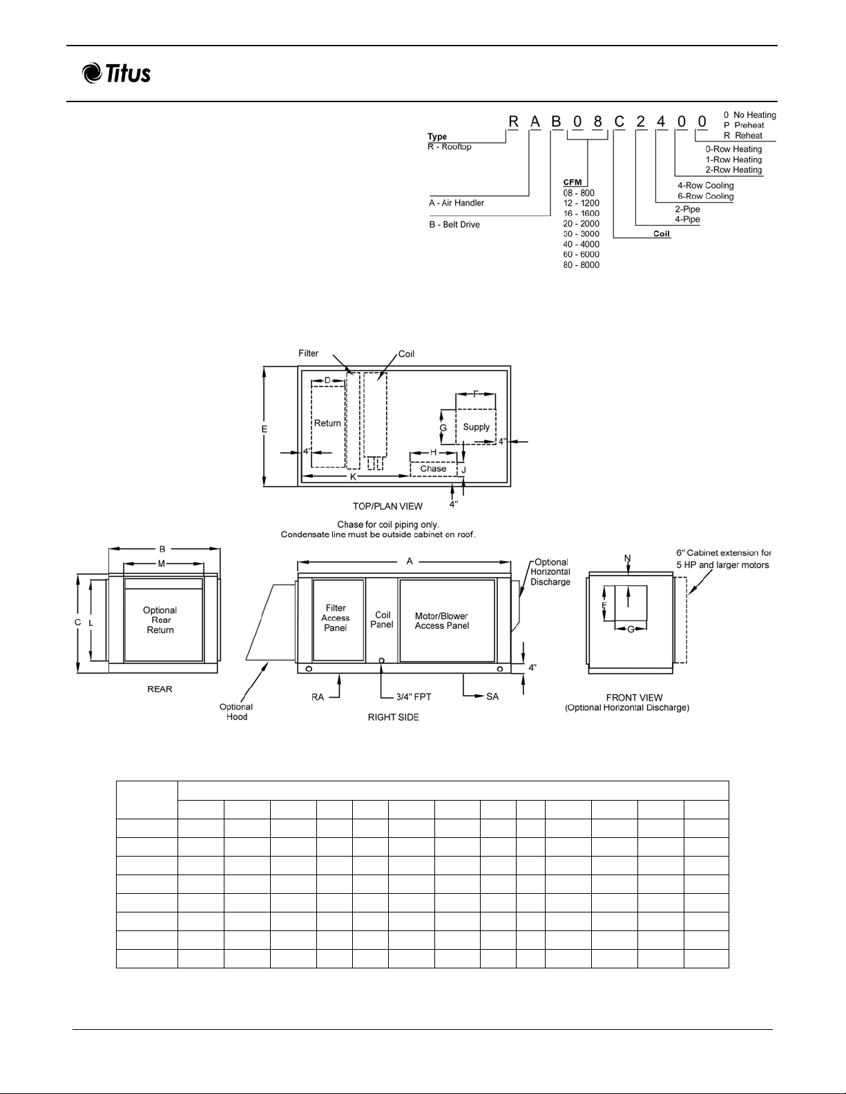
Model Number Specification
Figure 1 defines model number nomenclature specifics.
Page 2
RAB Installation Manual
Unit Cabinet Dimensions
Figure 2 provides dimensional callouts that correspond
to Table 1 information.
Service Data
Table 1 provides RAB model dimensions. Table 2
provides information such as tonnage, free area, water
coil connections, and filter sizes.
IOM-RAB-00 08-15-04
Shipping Weight
Table 3 provides RAB shipping weights (weight for 4row and 6-row chilled water coil includes weight for
entire unit).
Figure 1. Air Handler Model Number Nomenclature
Figure 2. RAB Dimensions
Table 1. RAB Unit Dimensions
Model
RAB08 67.3 39.5 22.5 12 26 11.9 8.9 10 8 35.5 14.2 28.4
RAB12 67.3 39.5 22.5 12 26 11.9 8.9 10 8
RAB16 72 48 26.5 12 34 14.1 9.5 10 8
RAB20 72 48 26.5 12 34 14.1 13.1 10 8 35.5 18 36
RAB30 72 53 40.5 14 44 16.4 13.4 15 8 37 24.3 46.1
RAB40 75 53 40.5 14 44 16.4 13.4 15 8 37 24.3 46.1
RAB60 75 53 54 14 44 16.4 19.4 15 8 41.2 33 46.1
RAB80 94 74 53.5 14 62 19 22 15 8 48.5 46 68.2
A B C D E F G H J K L M
Dimensions (inches)
2 of 10
35.5
35.5
14.2 28.4
18 36
N
2.5
2.5
3
3
12.3
12.3
25.8
17.5
Page 3

RAB Installation Manual
Table 2. Service Data
IOM-RAB-00 08-15-04
Model
RAB08 2 800 2.0 ¾ ¾ 5/8 16 x 32
RAB12 3 1200 3.0 ¾ 7/8 7/8 16 x 32
RAB16 4 1600 4.0 7/8 1-1/8 7/8 (2) 20 x 20
RAB20 5 2000 5.0 1-1/8 1-1/8 1-1/8 (2) 20 x 20
RAB30 7.5 3000 8.1 1-3/8 1-5/8 1-1/8 (2) 16 x 20
RAB40 10 4000 9.5 1-3/8 1-5/8 1-1/8 (2) 16 x 20
RAB60 15 6000 12.8 1-3/8 1-5/8 1-3/8 (3) 16 x 20
RAB80 20 8000 17.5 1-3/8 1-5/8 1-18
Note: All water coil connection sizes are outside diameter (OD) sweat (SWT) dimensions.
Nominal
Capacity
Model
RAB08 13 280 290 90 85 50 120
RAB12 18 280 290 90 85 50 120
RAB16 25 315 340 135 95 95 220
RAB20 30 410 420 135 95 95 220
RAB30 40 540 550 175 105 125 300
RAB40 45 580 590 175 105 125 300
RAB60 55 745 760 180 105 125 315
RAB80 75 950 970 200 120 145 410
2-Row
Coil
Nominal
CFM
4-Row
Unit
Coil Free
Area
(Sq. Ft.)
Table 3. Shipping Weights
Shipping Weight (lbs.)
6-Row
Unit
Water Coil Connection Size (inches)
4-Row 6-Row 2-Row
Modulating
Damper
Roof
Curb Kit
Manual
Damper
Filter Size
(inches)
(2) 16 x 25
(2) 16 x 25
(3) 16 x 25
(4) 16 x 20
(4) 16 x 25
Horizontal
Modulating
Damper
Installation
Basic installation procedure covers verifying and/or
installing the following items.
• Ductwork
• Duct insulation and vapor proofing
• Unit placement
• Sound attenuation
• Condensate drain
• Water piping
• Motors and drives
• Electrical connections
3 of 10
Ductwork
Use accepted industry practices and design guidelines of
the ASHRAE Fundamentals Handbook. Ductwork must
comply with all building codes and the NFPA pamphlet
90A and 90B.
Carefully inspect any previously installed ductwork to
determine suitability.
Note: Ductwork should be of a size meeting
requirements of the installation. Ductwork should
transition gradually from a smaller size blower outlet
to required du
air velocity.
ct run size to avoid excessive loss of
Page 4

RAB Installation Manual
Duct Insulation and Vapor Proofing
Previously installed heating supply ductwork may already
have adequate insulation against excessive heat loss.
This insulation may be satisfactory for protection against
heat gain from summer cooling. Depending upon
application, additional insulation may be required.
Externally insulated ductwork must have adequate vapor
seal for summer operation, especially where duct is
exposed to high humidity conditions.
IOM-RAB-00 08-15-04
Warning
Before installing unit, determine whether the unit
weight can be supported safely.
Possible injury and damage may result due to
joist/truss overloading.
When return air duct connection is smaller than return air
inlet opening, construct the transition piece so the vertical
and horizontal dimensions of transition do not increase
more than one inch for every seven inches of length.
Allow a minimum of three feet of straight ductwork
preceding equipment inlet
Sound Attenuation
Flexible duct connections should be used between the unit
and both the supply and return ducts. Requires unit
vibration isolation for suspended and base-mounted units.
Condensate Drain
Install unit with 1/8-inch pitch toward condensate drain
opening. Condensate drain must consist of a minimum of
¾-inch copper tubing, ¾-inch galvanized pi
PVC pipe. Figure 3 shows condensate drain setup. The
drain trap must be properly configured to ensure the
removal of all condensate runoff. Ensure drain pitches
downward at a slope of one inch every 10 feet.
Note 1: Incorrect trapping can hold water in pan,
causing overflow.
Note 2: Consult local codes for additional precautions
before installing condensate pan.
pe, or ¾-inch
Water Piping
All piping must be supported, independent of coils. Swing
joints or flexible fittings must be provided to absorb
expansion and contraction strains. Rigid piping reduces
the effectiveness of vibration isolators. The water supply
should always be connected so the entering w
the leaving airside of the coil. Coils must be adequately
vented in order to prevent air binding. See Figure 4.
Note: Freeze-ups due to low air temperatures are not
covered under the warranty agreement.
ater is on
Figure 3. Condensate Drain
Figure 4. Water Piping
Motors and Drives
Units are normally shipped with motor and drive installed.
However; when mounting a motor on the adjustable base
in the field, use extreme care to ensure proper alignment
and belt tension.
Electrical Connections
Each unit has a mounted control box and, typically, the
motor is to be wired to this box. Only ODP, single- and
three-phase motors on 800 to 2000 CFM units are factorywired to junction box. All other motors require field wiring
to junction box located on side of the unit cabinet.
Note: Unit must be permanently grounded in
accordance with NEC and local codes and
ordinances. See the typical wiring diagr
Figure 5.
ams shown in
4 of 10
Page 5

RAB Installation Manual
The manual air damper is designed to replace the end
return air access panel of the rooftop air
Figure 6 shows a manual air damper assembly and Figure
7 shows the placement of the manual air damper.
Preparation
• Upon receipt of materials, check shipping container
for damage. If damaged, contact shipping carrier.
• Unpack damper package and check contents against
packing list.
• Sort contents, especially fasteners, nuts, and bolts
according to size and type.
ELECTRIC SHOCK CAN CAUSE DEATH.
Caution: Disconnect all power supplies before
accessing equipment.
Disconnecting more than one power supply may
be required to de-energize some equipment.
Allow all rotating parts to completely stop before
attempting damper kit installation.
IOM-RAB-00 08-15-04
handler unit.
DANGER
Figure 5. Wiring Diagrams
Installation of Options
In addition to the standard equipment, the following
optional equipment may require consideration during
installation.
• Manual air damper.
• Motorized outside air damper.
• Roof curbs.
Manual Air Damper
Model RAB may be ordered with a manual air damper.
The manual air damper ships separately from the rooftop
air handler to be field assembled. The damper kit includes
the following components.
• Outside air damper.
• Intake hood.
• Frame rails (two sides, one top, and one bottom).
• Filter.
• Miscellaneous hardware for assembly.
Figure 6. Manual Air Damper Assembly
Figure 7. Manual Air Damper Attached
to RAB Unit
5 of 10
Page 6

RAB Installation Manual
IOM-RAB-00 08-15-04
Installation
1. Remove end return air panel and discard. See
Figure 7.
2. Attach side frame rails using sheet metal screws as
provided (size 10 x ¾-inch with bonded-seal
washers).
3. Attach top frame rail using sheet metal screws as
provided.
4. Attach bottom frame rail using sheet metal screws
as provided.
5. Attach manual outside air damper, intake hood, and
filter assembly.
Motorized Air Damper
The motorized outside air damper kit can be used only
with the manual air damper. The motor kit components
consist of the motor operator, hood assembly, hardware
(fasteners and screws), and installation instructions.
Figure 8 shows the motor placement onto a manual
ation air damper.
oper
Only qualified and trained HVAC technicians should install
the motorized outside air damper kit.
The instructions serve as guidelines to the technician
installing the kit.
Preparation
• Upon receipt of materials, check shipping container
for damage. If damaged, contact shipping carrier.
• Unpack the motor assembly that includes the motor
operator, operator hood assembly, and instructions.
• Sort contents, especially fasteners, nuts, and bolts
according to size and type.
DANGER
ELECTRIC SHOCK CAN CAUSE DEATH.
Caution: Disconnect all power supplies before
accessing equipment.
Disconnecting more than one power supply may
be required to de-energize some equipment.
Allow all rotating parts to completely stop before
attempting damper motor kit installation.
Installation
1. Remove filter from bottom of the fresh air intake.
2. Remove handle from the outside of the fresh air
intake. Damper rod should extend beyond unit
exterior.
3. Position damper blade to its fully closed position.
4. Press manual override button and rotate actuator
clamp to about 1/16 and 1/8-inch between actuator
stop and clamp.
5. Slide actuator over damper rod and finger-tighten
nuts.
6. Slide an
actuator engaging center cutout on actuator back,
see Figure 9.
ti-rotation bracket (L-bracket) up and under
Figure 8. Air Damper Motor Placement onto
Damper Shaft
Figure 9. Mounting Bracket Placement
6 of 10
Page 7

RAB Installation Manual
IOM-RAB-00 08-15-04
7.8.Use self-tapping screws to secure bracket.
Tighten the two nuts on the universal clamp with
8 mm wrench, 3-5 ft. lb. torque.
Note: Actuator compresses damper blades
upon reaching the end position creating an
airtight damper.
10. Wire motor as shown in Figure 10. 14. Restore power to system.
11. Activate motor until blade reaches desired opening
and tighten the setscrew. Figure 11 shows setscrew
location.
12. Slide the rain cover over motor and use sheet metal
screws to secure the cover.
tresnI .31 .deriuqer fi ,spots dne tsujdA .9 filter in the bottom of the fresh air intake.
Figure 10. Wiring Diagram
7 of 10
Page 8

RAB Installation Manual
Figure 11. Motor Calibration
IOM-RAB-00 08-15-04
Roof Curbs
Roof curb assemblies require field assembly and are
shipped separately, knocked down. Select a level and
structurally adequate location to support the combined
weight of the roof curb, air handler, and plenum. The
following table provides a list of components for a roof curb
installation. Figure 13 serves as a reference diagram for roof
curbs.
Preparation
• Upon receipt of materials, check shipping container for
damage. If damaged, contact shipping carrier.
• Place roof curb kit on roof deck for assembly.
• Unpack roof curb package and check contents against
packing list.
• Sort contents, especially fasteners, nuts, and bolts
accor
ding to size and type.
Note: Wood or fiber strips, roofing felts, roofing
materials, caulking, adhesive gasket material, and curb
to roof fasteners are field supplied.
Figure 12. Roof Curb Assembly Diagram
8 of 10
Page 9

RAB Installation Manual
IOM-RAB-00 08-15-04
Installation
1. Assemble the 2 x 4 wood nailer to the short and long
roof curb frame sides using 12 x 12 Hex TEKS
Neoprene fasteners and washers.
2. Bolt together, forming a rectangle, the long and short
roof curb frame sides.
Note: Leave bolts loose allowing for adjustment
later.
3. Assemble the long and short roof curb supports
using the 10 x ½ serrated head bolts.
4. Position the assembled long and short supports to
the inside of the roof curb frame.
5. Secure supports to roof curb frame using 10 x ½
with serrated 5/16 head bolts.
6. Check to be sure frame is squared.
7. Tighten fasteners, bolts and nuts.
8. Position roof curb assembly over roof opening and
check again to be sure ass
Note: Frame must be within ¼ inch of being
squared.
9. Secure curb to structure.
10. Apply ¼ x 1-½ inch adhesive gasket material around
the roof curb top and duct cross channels.
11. Roof curb is complete and ready to receive air
handler unit.
embly is squared.
®
with
Air Handler Startup
Check the following items before startup.
• Ensure all shipping bolts/screws are removed and all
other bolts and screws are tight.
• Verify motor voltage and phase. Never assume the
voltage and phase on the unit nameplate is the same
as the motor wired.
• Check the alignment of the sheaves and ensure the
setscrews are tight.
• Check for proper rotation of the blower pulley.
• Check motor phase and rotati
− Exchanging two of the three leads at the unit
junction box can reverse three-phase motor
rotation.
− Exchanging leads inside the motor junction box
can reverse the rotation of single-phase motors.
Refer to the motor nameplate.
− Not all installations require a starter (some
motors utilize a contactor).
on.
• Ensure all filters are installed. Perform filter check
with all doors and panels in place.
• Check the amperage draw of the motor. The
amperage draw should not exceed the nameplate
amps shown on the motor serial plate.
Operation and Maintenance
Heed the following warning before operation or
maintenance.
Warning: Disconnect electrical power to all circuits
before servicing unit. Failure to do so may result in
personal injury from electrical shock or moving parts.
Return Air Filters
Inspect return air filters on a regular basis (at least
monthly). Clean or replace filters. Filters can be accessed
from either side of unit.
Caution: Never operate unit without a filter or with
filter access door removed. Damage to blower
motor may result.
Coil
The coil is easily cleaned when dry. To check or clean,
remove unit access panel, filter access door and filters.
Use accepted industry methods for cleaning. Remove all
foreign matter from pan and condensate drain line. Check
for rust and holes.
Belt and Pulley
The following list highlights items to consider for belt and
pulley maintenance and adjustment.
• Proper pulley alignment and belt tension must be
maintained at all times.
• Reduce speed by adjusting pulley faces so the faces
are further apart.
• Increase speed by moving the faces closer together.
• Check pulley setscrews and bolts.
Motor
Proper lubrication is essential to long motor life. Use
electric motor oil or SAE20 non-detergent oil. Tighten
motor mount bracket and base bolts.
Note: Avoid over-oiling the motor. If a motor is overoiled, the oil may run down the motor shaft and
splatter.
Blower
Periodically check bearing for wear. Replace as required.
Check wheel for dirt accumulation and clean as
required.
9 of 10
Page 10

RAB Installation Manual
Abbreviations
The following table lists the abbreviations found within this
document.
Abbrev. Term
ASHRAE American Society of Heating Refrigeration
Air-Conditioning Engineers
CFM cubic feet per minute
CW cold water, chilled water
fpt female pipe thread
HVAC Heating, Ventilation, and Air Conditioning
MTR Motor
NEC National Electric code
NFPA National Fire Protection Association
OD outside diameter
ODP open-drip proof
PVC polyvinyl chloride
RA return air
SA supply air
SAE Society of Automotive Engineers
SWT sweat
IOM-RAB-00 08-15-04
10 of 10
Page 11

Air Handler
Terms and Conditions
Warranty
The following terms and conditions apply to and govern
the sale of the air handling equipment and parts
manufactured by Titus.
EXCLUSIVE TERMS OF SALE – Titus quotes and sells its
goods on the expressed condition that the buyer assents to
the terms and conditions set forth herein, regardless of any
inconsistent or additional terms that may be embodied in
any purchase order. Titus’ sale of its goods is expressly
conditional on the buyer’s acceptance and receipt of the
goods shall constitute the buyer’s assent to such terms and
conditions.
ACCEPTANCE – All orders are subject to Credit and Sales
Department approval and acceptance. Titus reserves the
right, among other remedies, to terminate or suspend
further delivery against an order in the event the buyer fails
to pay any portion of the order when it becomes due.
Should buyer’s financial condition become
Titus, cash payment or satisfactory security may be required
by Titus for further deliveries or for goods already delivered.
CANCELLATION – Buyer shall not cancel the order without
prior written consent of Titus. In the event buyer cancels the
order with the prior written consent of Titus after the buyer’s
offer to purchase is received and acknowledged in writing,
Titus shall be entitled to receive from the buyer Titus’ cost
plus 15% administrative overhead and liquidated damages
in the amount of 10%. Furthermore, for goods released for
production but prevented by buyer from shipping upon
completion or by the acknowledged shipping date,
whichever is later, Titus may, at its option, in addition to all
other remedies, invoice buyer to be payable within 30 days
and store the goods at buyer’s
DELIVERIES – Any stated shipping date of the goods is
Titus’ best estimate based upon the volume of orders for the
goods Titus has received or expects to receive at the time it
receives buyer’s order. TITUS MAKES NO GUARANTEE
OF SHIPMENT BY THE ESTIMATED DATE AND SHALL
HAVE NO LIABILITY OR OTHER OBLIGATION,
INCLUDING, BUT NOT LIMITED TO INCIDENTAL OR
CONSEQUENTIAL DAMAGES THE BUYER OR ANY
THIRD PARTY MAY INCURE, FOR ITS FAILURE TO
SHIP BY SUCH DATE, REGARDLESS OF CAUSE.
SHIPMENTS –Titus shall not be bound to deliver any goods
for which buyer has not given shipping instructions. ALL
PRODUCTS ARE SOLD F.O.B. SELLER’
TO GOODS PASSES TO THE BUYER UPON DELIVERY
BY TITUS TO THE FREIGHT LINE. All goods are shipped
at buyer’s risk. Buyer should examine shipments carefully
for loss or damage and should have same noted by
transportation agent on the freight bill upon accepting
delivery. In the event of concealed damage, buyer has 10
days from receipt of the goods in which to call the freight
line for an inspection.
In either case, the equipment cannot be returned to Titus
until after a freight inspection has been completed. In
absence of shipping instructions, Titus shall use its own
discretion in choice of carrier.
TAXES – Sales, use, consumption, storage or other taxes, if
applicable, shall be paid by the buyer.
sole expense.
unsatisfactory to
S PLANT. TITLE
RETURN GOODS – New and unused goods returned for
credit will not be accepted unless a Return Goods
Authorization number has bee
must be securely packed to reach Titus without damage and
properly identified with the Return Goods Authorization
number. RGA numbers are valid for only 30 days after
issuance. A minimum 20% fee will be charged on all stock
products cleared for return that can be returned to stock
after inspection. Build-to-order products manufactured and
shipped cannot be returned and a 100% cancellation fee
applies to any order that has been released for production
but has not shipped. All goods must be returned freight
prepaid by the buyer.
ALL PRODUCTS LIMITED WARRANTY – Titus warrants
that its goods will be free from defects in material and
workmanship under normal use and maintenance for a
period of one year from the date of original installation or 18
months from the date of shipment whichever comes first. A
new or rebuilt part to replace any defective part w
provided without charge, PROVIDED the defective part is
returned to Titus. The replacement part assumes the
unused portion of the warranty.
THIS WARRANTY DOES NOT INCLUDE LABOR or other
costs incurred for identifying, repairing, removing, installing,
shipping, servicing, or handling of either defective parts or
replacement parts.
TITUS WILL NOT BE RESPONSIBLE FOR:
1. Normal maintenance.
2. Damage or repairs required as a consequence of faulty
installation or application by others.
3. Failure to start due to voltage conditions, blown fuses,
open circuit breakers, or other damages due to the
inadequacy or interruption of electrical service.
4. Damage or repairs required as a consequence of any
misapplication, abuse, improper servicing,
unauthorized alteration, or improper operation.
5. Damage as a result of floods, winds, fires, lightning,
accidents, corrosive atmosphere, or other conditions
beyond the control of
6. Parts not supplied or designated by Titus.
7. Titus products installed outside the United States and
Canada.
FOR SERVICE OR REPAIR FOLLOW THESE STEPS IN
ORDER:
FIRST: Contact the installing contractor.
SECOND: Contact the distributor or nearest authorized
Titus representative.
THIRD: Contact
TITUS
990 Secur
Richardson, TX 75080
972.699.1030
THIS WARRANTY IS EXCLUSIVE AND IN LIEU OF ALL
OTHER WARRANTIES EXPRESS OR IMPLIED,
INCLUDING, WITHOUT LIMITATION, THE IMPLIED
WARRANTIES OF MERCHANTABILITY AND FITNESS
FOR A PARTICULAR PURPOSE.
n issued by Titus. Goods
ill be
Titus.
ity Row
1 of 2
Page 12

Terms and Conditions
Warranty
BUYER’S EXCLUSIVE REMEDY – The buyer’s acceptance
of the goods shall confirm the buyer’s review and
acceptance of Titus’ All Products Limited Warranty,
notwithstanding any other written or oral warranty of the
goods that may be given to the buyer. THE BUYER’S
EXCLUSIVE REMEDY AGAINST TITUS SHALL BE
LIMITED TO TITUS’ ALL PRODUCT LIMITED
WARRANTY. NO OTHER REMEDY, INCLUDING, BUT
NOT LIMITED TO, RECOVERY FOR INCIDENTAL OR
CONSEQUENTIAL DAMAGES FOR LOST PROFITS,
LOST SALES, INJURY TO PERSON OR PROPERTY, OR
ANY OTHER INCIDENTAL OR CONSEQUENTIAL LOSS,
SHALL BE AVAILABLE TO THE BUYER.
LD MODIFICATIONS – Should the installing contractor
FIE
believe that the goods do not meet the requirements of the
original submittal or do not operate according to the
submittal, the buyer should immediately contact the selling
distributor or authorized Titus representative as outlined in
the All Products Limited Warranty section. Upon Titus’
acceptance of responsibility to make modifications to the
goods, Titus will, at its sole discretion, either direct the
contractor to make the modifications, send its own field
service technicians to make the modifications, or engage
another contractor to make the modifications. If Titus directs
the installing contractor to make the modifications, Titus will
issue a Field Repair Order (FRO) specifying the work to be
done and the price to be paid. DO NOT BEGIN ANY
MODIFICATIONS WITHOUT AN FRO NUMBER. Titus will
not be responsible
goods, unless it has approved the modifications in advance.
for any costs incurred in modifying the
EXCUSE OF PERFORMANCE – Titus shall not be liable for
its failure to perform due to causes beyond its reasonable
control, including but not limited to strikes, fire, war, acts of
God, whether such events occur at or about Titus’ plant or
at the plant of its suppliers.
CREDIT AND TERMS OF PAYMENT – Unless otherwise
specified, terms of payment are net cash, thirty (30) days
after shipment. Interest at the legal rate applicable to
judgments will be charged on past due accounts
commencing after the last day of the first calendar month
following the date of invoice. Seller may suspend credit and
refuse shipment whenever seller in its sole discretion
believes buyer’s credit is unsatisfactory unless buyer then
makes arrangements for
seller.
MISCELLANEOUS – THESE TERMS AND CONDITIONS
FOR THE SALE OF THE GOODS SHALL BE
CONSTRUED ACCORDING TO THE LAWS OF THE
STATE OF TEXAS. ALL SUMS DUE TITUS FOR THE
SALE OF ITS GOODS ARE PAYABLE, AND ALL
MATTERS ARISING PURSUANT TO SUCH SALE ARE
PERFORMABLE, IN DALLAS COUNTY, TEXAS. The
terms and conditions state herein constitute the full
understanding between Titus and the buyer, and no terms,
conditions, understanding or agreement purporting to
modify or vary these terms shall be binding unless hereafter
made in writing and signed by Titus and the buyer.
Titus has a policy of continuous product improvement,
and reserves the right to cha
specification without notice. Titus has no system
design or application responsibility to buyer or any
third party.
payment which are satisfactory to
nge design and
2 of 2
 Loading...