

Page 1
H**
QCV Series Retrofit Terminals
1
10
Gasket
2
QCV-IOM-1.0 2-28-13
Opening in Duct by Others
Airflow
18"
1
6
2
W**
1
12
4
Orifice plate is undersized
1
" for
4
easy assembly. Additional Gasket
must be field supplied to assure a
tight seal.
Multi-Point
Center Averaging
Velocity Sensor
17"
1
H +
8
Control Enclosure
Gasket
Optional
Mounting
Plate
Disconnect
Switch
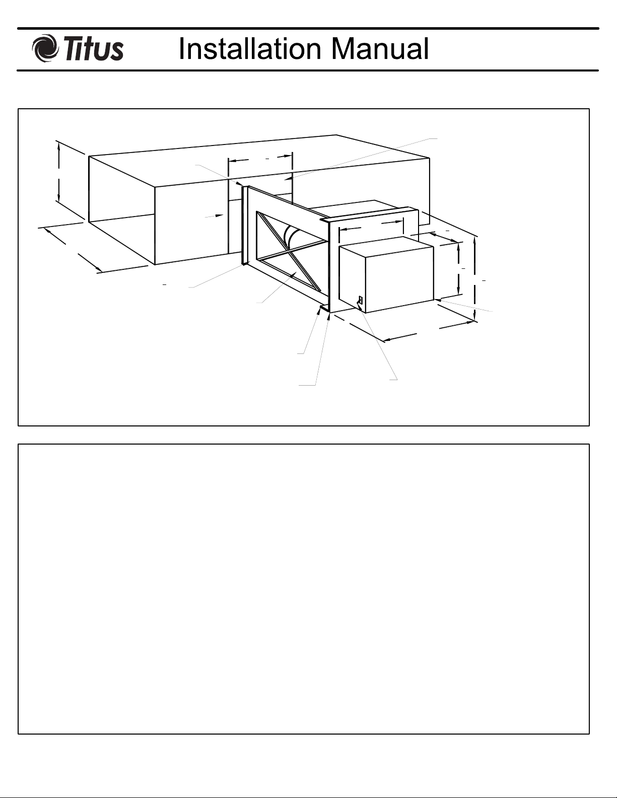
Installation
To install, simply cut a rectangular opening in the side of the duct. The opening should be the height of the duct and 10 ½
inches wide as shown above. If the duct is internally lined with insulation, cut out a 1 inch wide groove of insulation down
to the sheet metal duct. The groove should be in line with the duct plate which has the mult-point center averaging velocity
sensor mounted in it. Duct sealer can now be applied to the bottom inside section of the duct, which aligns with the duct
plate. The duct plate has a 1 inch wide flange for duct sealer to be applied to the top edge as well. The flange can be used
as well for attachment to the duct with sheet metal screws. After the retrofit valve is inserted into the duct with duct sealer
on the top and bottom edges of the duct plate, the valve assembly should be firmly attached to the duct with sheet metal
screws in the mounting plate and the duct plate plate flanges. The corner reinforcing angles should be attached to the top
and bottom of the mounting plate as shown. A sealer may also be used to decrease leakage along the reinforcing angles.
The controls are now ready to be piped and activated. Please note that the valve is always installed so the damper is
down stream from the air flow sensor.
Important:
See
sheet 2 for the QCV
K-factors.
Page 2
y
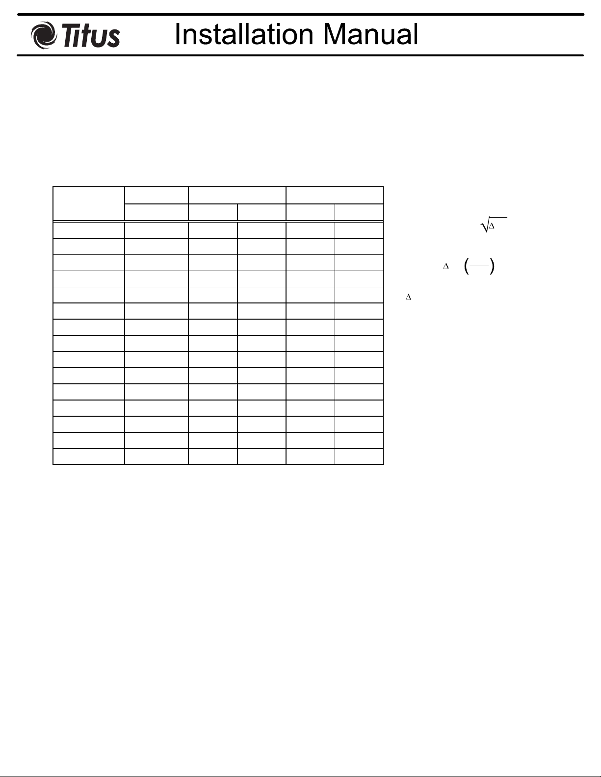
AeroCross Sensor - Calibration Curves
Inlet Sensor Applications (For QCV's)
QCV-IOM-1.0 2-28-13
Unit Damper
K-Factor Sensor
Size SQ FT CFM FPM Quantit
A 0.174 320 1837 1 4/5
B 0.250 477 1908 1 4/5
C 0.333 629 1890 1 4/5
D 0.555 1047 1886 1 8
E 0.778 1539 1978 1 8
F 0.750 1472 1962 2 4/5
G 0.833 1676 2012 1 10
H 1.250 2619 2095 2 10
J 1.500 3036 2024 1 12
K 1.944 4385 2256 1 16
L 2.500 5582 2233 2 12
M 2.444 5847 2392 1 16
N 3.000 7413 2471 1 16
P 4.167 11224 2693 2 16
R 5.555 16496 2970 2 16
Size
Equations:
CFM
K
P
2
CFM = K
P =
P = Differential Pressure On AeroCross,
IN WG
K = Flow Required To Produce A 1.0 IN WG
Differential Pressure On AeroCross,
CFM
 Loading...