

Page 1
Installation Manual
Linear Slot Ceiling Diffusers
Aluminum • Modulinear
Models: ML-37 •
ML-38 •
ML-39 • 1” Slot • Supply
MLR-37 •
MLR-38 •
MLR-39 • 1” Slot • Return
1
/2” Slot • Supply
3
/4” Slot • Supply
1
/2” Slot • Return
3
/4” Slot • Return
D-ML-IM 2-28-13
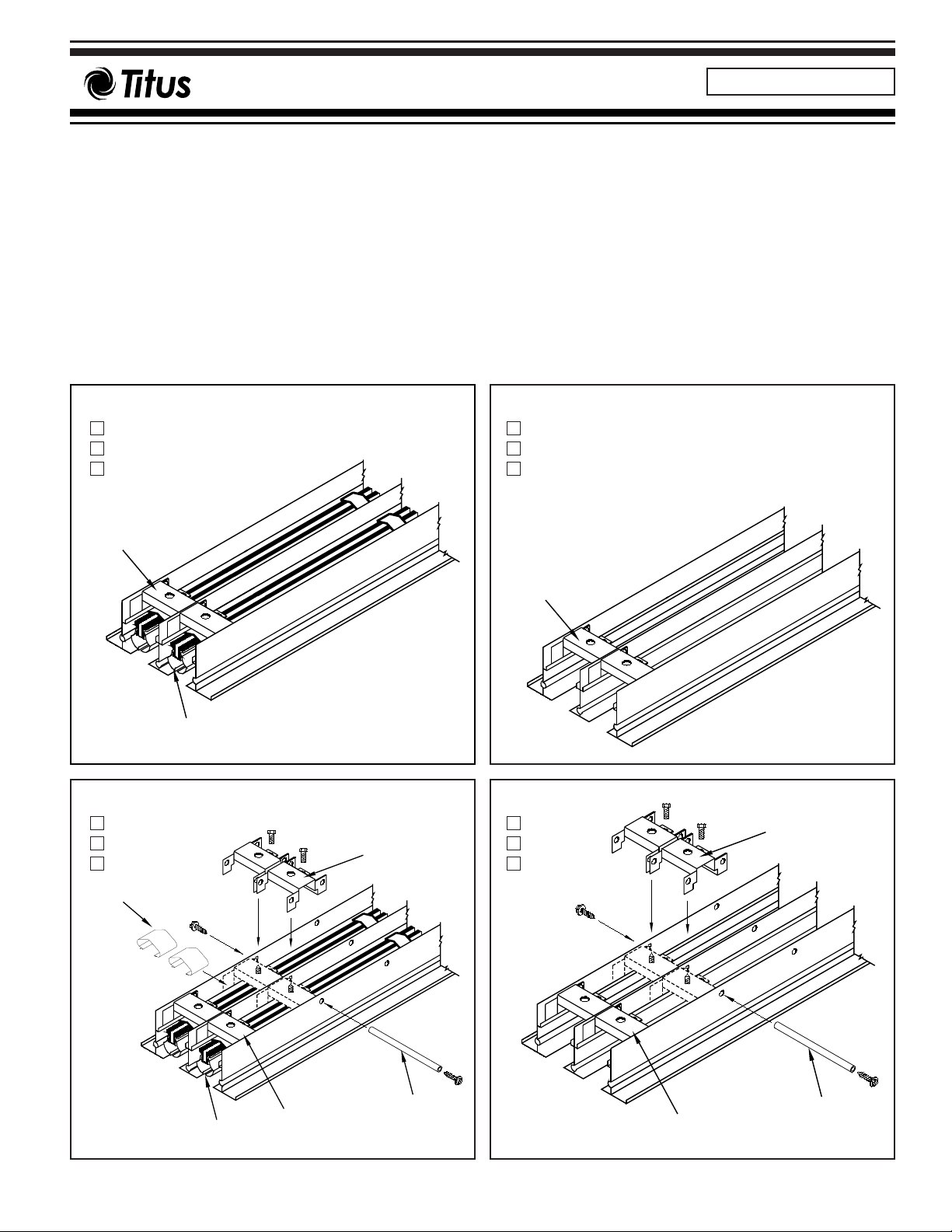
Factory Cut Supply
ML-37
ML-38
ML-39
Factory
Spacer
Pattern
Conrtoller
Factory Cut Supply
ML-37
ML-38
ML-39
Field
Spacer
Factory Cut Return
MLR-37
MLR-38
MLR-39
Factory
Spacer
Factory Cut Return
MLR-37
MLR-38
MLR-39
Field
Spacer
Spring Clips
Pattern
Conrtoller
Factory
Spacer
Tube
Dimensions are in inches.
Factory
Tube
Spacer
Y-?.0-S
Page 2
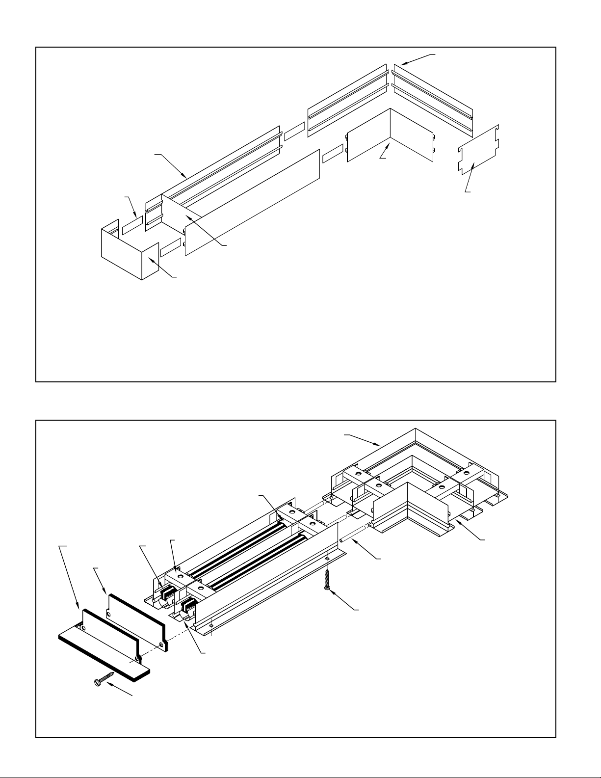
End Fabrication
(Factory Welded)
End Frame
Strip
Alignment
Rail
Side
Assembled
Gauge
Temporary
Corner
Field
Temporary
Gauge
Corner
Field Assembled
Diffuser Assembly Instructions
#8 x 1 1/4 Oval Head Screw
(Border Type 1A only)
(Welded)
Factory
Spacer
#6 x 1/2 SMS
Optional
End Cap
End Border
Optional
Blade
Bar
Support
Controller
Pattern
Spring Clip
Alignment
Pins
Corner
Mitered
Blank-Offs
Optional
1. Determine size of duct opening. Duct width depends upon model,
frame & border type and number of slot. See Duct Dimensions D’
table (Page 7). Duct length is as ordered.
2. First install end frames and field assembled corner pieces in ceiling
opening. Then cut side rails to length and install. Use alignment strips
furnished with frame parts to connect side rails, corners and end
frames to each other.
Note: When end borders are not to be used with diffuser, mounting
frame ends are not furnished.
3. Use removable gauges furnished with frame parts to ensure
proper fit of diffuser into mounting frame. Gauges snap into place
between side rails as shown above. If mounting frame is to be plastered into place, use wood blocks to stiffen side rails and maintain
correct inside dimensions.
1. Assemble diffuser with alignment pins as shown above. End
borders or caps, where ordered, are attached at factory.
2. Install diffuser in ceiling. See Hanger Bracket Mounting
Instructions (Page 4).
Note: Mounting frame is used only on
Frame & Border Types 3, 4, 6, 7A, 7B, 11.
2
Page 3
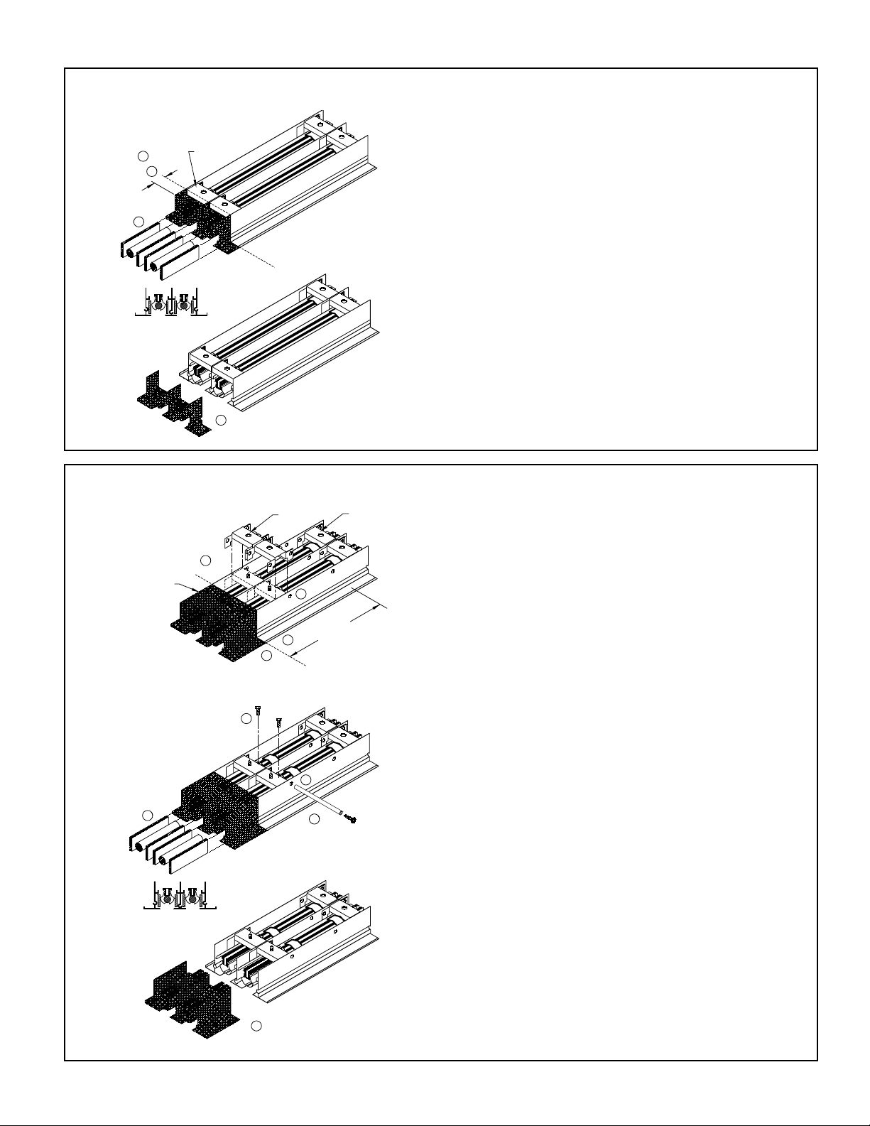
Field Cut Diffuser
3
Field Cutting Instructions
Factory Cut Diffuser (Trimming)
1. Message length of diffuser to be cut.
2. Mark ML or MLR for cut. You can cut as much as 3” on each
end for a maximum of 6”. Do not cut passed weld spacer.
3. Insert 1/2” dowel into center of each pattern controller. Insert
wood blocks or dowels on outside of pattern controller. Wood will
support pattern controller when cutting through diffuser.
4. Cut ML or MLR with circular saw. Recommended metal cutting saw blade:
14 x 152 teeth or
10 x 80 teeth
3/32 “ thickness.
Apply lubricant while cutting.
1. Message length of diffuser to be cut.
2. Mark MLF or MLRF for field cut. NOTE: If 6” or less is to be cut off,
use Trimming instructions shown above. To ensure proper support of
pattern controller deflector blades, there should be 7” or less between
end of diffuser and next spacer. If after marking their is more than 7”
between the field cut mark and the factory spacer, install field spacer.
If field spacer is required
3. Line up wholes on side of field spacer with predrilled holes in diffuser. Make sure field cut is between factory weld spacer and field
spacer.
4. Installed tube through diffuser field spacer. Next install screws in
both ends of the tube and tighten.
5. For MLF with pattern controllers, install screw through lower tab
hole of field spacer and tighten into threaded channel on blade support
bar.
6. For MLF with pattern controllers install additional spring clips on top
of blade support bar. Place clip 2” from edge or directly behind spacer
if space is in the way. See spring clip for detail, Page 4.
7. Insert 1/2”dowel in center of each controller. Insert wood blocks or
dowels on outside of pattern controller. Wood support pattern controller
when cutting through diffuser.
8.Cut MLF or MLRF with circular saw. Recommended metal cutting
saw blade:
14 x 152 teeth or
10 x 80 teeth
3/32” thickness
Apply lubricant while cutting.
Spacer
Factory
1
3
Spacer
Field
Spacer
Factory
1
Field Cut
use field spacer
If more than 7"
2
7
5
4
6
8
3" Max
3
2
1
Spacer
Factory
Do not cut
past spacer
Trim
4
Page 4

4
Spring Clip - Attaching to Field Cut Diffuser
1
2
To attach spring clip to field cut diffuser:
1. Start spring clip on side of blade support bar.
2. Use needle nose pliers or screwdriver to
expand spring clip until it hooks over other side of
blade support bar.
Hanger Bracket Mounting Instructions
1
1. Drill through top of blade support with
7/32” drill. Use hole in top of field spacer
as guide for drill.
Note: Blade supports are pre-drilled
under factory spacers at at end of
diffusers
2. Hole in blade support will be used as
clearance hole for inserting screw
through face of diffuser, upward into
hanger bracket.
Field Cut Diffuser Only - All Frame & Border Types
1. Insert #10 screw through face of
diffuser, through hole in blade support
and into foot of hanger bracket above
diffuser.
2. Attach hanger wires (by others).
1. Insert #10 screw through face of
diffuser, through hole in blade support.
Start screw in top of hanger bracket
above diffuser.
Note: See submittal Y-ML for duct
dimension D’.
2. Side diffuser up into duct until
hanger bracket ends are above hem of
duct.
3. Tighten screws to draw diffuser
border snug against ceiling.
Caution: Do not overtighten.
1. Insert #10 screw through face of
diffuser, through hole in blade support.
Start screw in top of hanger bracket
above diffuser.
2. Side diffuser up into mounting
frame until hanger bracket ends are
above channel on inside of mounting
frame.
3. Tighten screws to draw diffuser
border snug against ceiling.
Hanger Bracket
for Border
Types 9A, 9B, 12, 15
Hanger Bracket
for Border
Types 2A, 2B
Hanger Bracket
for Frame & Border
Types 3, 4, 6, 7A, 7B, 11
2
1
2
1
3
2
1
3
2
Page 5

Horizontal Left
5
Pattern Controller Blade Settings
Frame & Border Types, Dimensions
for #8 SMS (5/16 from Edge)
Countersunk Screw Holes
O’= D’+ 7/8
3/4
S
D’=Duct Size
1/8
1 1/8
1 3/4
Supply
Model ML-37 S=1/2”
ML-38 S=3/4”
ML-39 S=1”
Return
Model MLR-37 S=1/2”
MLR-38 S=3/4”
MLR-39 S=1”
Border Type 1A
With
• Flange Border
• Screw Mounting
Border Type 1B
With
• Flange Border
• Duct Mounting
Border Type 2A
Border Type 2B
Both with
• Flange Border
• Concealed Mounting
Type A O’
2A 1 1/8D’+ 3/
4
2B
7
/8D’+ 1/
4
† See Page 7
Horizontal Right
Dampered
Horizontal Left
Vertical Fully Dampered
Opposed
One Way Vertical & Horizontal
Opposed Unequal Flow
(One Slot Dampered)
S
S
S
S
D’=Duct Size
D’=Duct Size
3 5/16"
3/4
O’= D’+ 7/8
1 3/4
S
1/8
1 1/8
1/8" to 1/2"
3/4"
O’
S
1 3/4"
1/8"
A
Page 6

Frame & Border Types, Dimensions (Continued)
† See Page 7
Frame & Border Type 3
With
• Flush Border
• Concealed Mounting
Frame & Border Type 4
With
• Flange Border
• Concealed Mounting
Frame & Border Type 6
With
• Plaster & Tile Mounting Frame
• Flush Border
• Concealed Mounting
Frame & Border Type 7A
Frame & Border Type 7B
Both with
• Plaster & Tile Mounting Frame
• Flange Border
• Concealed Mounting
Border Type 9A
Border Type 9B
Both with
• Flange Border
• Ceiling Hangers
Border Type II
With
• Perimeter Plaster & Tile
Mounting Frame
• Flush Border
• Concealed Mounting
Border Type 12
With
• Spline Border
• Ceiling Hangers
Border Type 15
With
• Flush Border
• Ceiling Hangers
Border Type 16
With
• Curved Flange Border
• Concealed Mounting
• Equalizing Grid
Border Type 16 standard selections:
ML-38 only
1 slot: duct diameters 10, 14, 18, 22, 24”
2 slot: duct diameter 14, 18, 22, 24”
6
Type A O’
7A 1 1/8D’+ 3/
4
7B
7
/
8
D’+ 1/
4
Type A O’
9A
3
/4D’+ 3/
4
9B 1 7/8D’+ 1 3/
8
D’=Duct Size
3/4"
S
O’=D’minus1/8"
3/4"
D’+1 1/4
D’+1/2
D’=Duct Size
3/4
S
O’
1/8
A
1 7/8"
1 1/16
9/16
3 5/16"
1 15/16
3 5/16
D’=Duct Size
3/4
O’=D’+3/4
D’=Duct Size
3/4"
S
O’
3 5/16
1 15/16
1 1/8
1/8
S
D’+1 1/4
D’+1/2
D’=Duct Size
3/4
S
O’=D’-1/8
3/4
1/2
1
3 5/16
1 7/8
Hanger
3 1/8"
1 3/4"
1/16"
A
D’=Duct Size
3/4
O’=D’-1/8
3/4
3 5/16
1 7/8
1
1/2
S
3/4
1 3/16
1/4
D'=Duct Size
S
3/4
7/16
O'=D'-1/16
Hanger
3 1/8
1 3/4
7/16
1 1/16
D'=Duct Size
S
3/4
O'=D'-1/16
Hanger
3 1/8
1 3/4
7/16
DUCT BY OTHERS
1/2 X 1/2 X 1/2
ALUMINUM
EQUALIZING GRID
3/4
1 1/8
Page 7

D = Duct Size
O
C
End Fabrication
Overall Length for Various End Fabrications
Duct Dimensions D’ (Width) for Various Frame & Border Types
X End Border Y Open End Z End Cap
Frame
and/or
Border
Type
XXXYXZYYYZZZ
X-X X-Y X-Z Y-Y Y-Z Z-Z
CO CO CO CO CO CO
1A, 1B, 9B D - 1
3
/8D + 3/4D - 11/16D + 3/8D + 5/8D + 7/
16
D D D + 1/16D + 1/16D + 1/8D + 1/
8
2A, 4, 7A, 16 D - 1 3/8D + 3/4D - 11/16D + 3/8D + 5/8D + 7/
16
D D D + 1/16D + 1/16D + 1/8D + 1/
8
3, 6, 11 D - 1 3/
8
DD - 11/
16
DD + 5/8D + 1/
16
D D D + 1/16D + 1/16D + 1/8D + 1/
8
2B, 7B D - 1 3/8D + 1/4D - 11/16D + 1/8D + 5/8D + 3/
16
D D D + 1/16D + 1/16D + 1/8D + 1/
8
9A D - 1 3/
8
DD - 11/
16
DD + 5/8D + 1/
16
D D D + 1/16D + 1/16D + 1/8D + 1/
8
12, 15 D - 1 11/
16
DD - 5/
16
DD + 1/4D + 1/
16
D D D + 1/16D + 1/16D + 1/8D + 1/
8
Types 1A, 1B Types 2A, 2B, 4, 7A, 7B, 16 Types 3, 6, 11 Types 9A, 9B Types 12, 15
ML/MLR ML/MLR ML/MLR ML/MLR ML/MLR ML/MLR ML/MLR ML/MLR ML/MLR ML/MLR ML/MLR ML/MLR ML/MLR ML/MLR ML/MLR
37 38 39 37 38 39 37 38 39 37 38 39 37 38 39
S =
1
/2S = 3/4S = 1 S = 1/2S = 3/4S = 1 S = 1/2S = 3/4S = 1 S = 1/2S = 3/4S = 1 S = 1/2S = 3/4S = 1
11 7/
8
2 1/
8
2 3/
8
22
1
/
4
2 1/
2
2 1/
8
2 3/
8
2 5/
8
1 3/
8
1 5/
8
1 7/
8
1 3/
8
1 5/
8
1 5/
8
23 1/
8
3 5/
8
4 1/
8
3 1/
4
3 3/
4
4 1/
4
3 3/
8
3 7/
8
4 3/
8
2 5/
8
3 1/
8
3 5/
8
2 5/
8
3 1/
8
3 5/
8
34 3/
8
5 1/
8
5 7/
8
4 1/
2
5 1/
4
64
5
/
8
5 3/
8
6 1/
8
3 7/
8
4 5/
8
5 3/
8
3 7/
8
4 5/
8
5 3/
8
45 5/
8
6 5/
8
7 5/
8
5 3/
4
6 3/
4
7 3/
4
5 7/
8
6 7/
8
7 7/
8
5 1/
8
6 1/
8
7 1/
8
5 1/
8
6 1/
8
7 1/
8
56 7/
8
8 1/
8
9 3/
8
78
1
/
4
9 1/
2
7 1/
8
8 3/
8
9 5/
8
6 3/
8
7 5/
8
8 7/
8
6 3/
8
7 5/
8
8 7/
8
68 1/
8
9 5/
8
11 1/88 1/
4
9 3/
4
11 1/
4
8 3/
8
9 7/811 3/
8
7 5/
8
9 1/810 5/87 5/
8
9 1/
8
10 5/
8
79 3/
8
11 1/812 7/89 1/
2
11 1/
4
13 9 5/
8
11 3/813 1/
8
8 7/
8
10 5/812 3/88 7/
8
10 5/812 3/
8
8 10 5/812 5/814 5/810 3/412 3/414 3/410 7/812 7/814 7/810 1/812 1/814 1/810 1/812 1/814 1/
8
7
No.
of
Slots
D = Duct Size
C
C
D = Duct Size
O
O
Page 8

Accessories (Optional) Check if provided
Optional Miter Corner
MLF-37 • 1/2” Slot
MLF-38 • 3/4” Slot
MLF-39 • 1” Slot
O
D = Duct Size
Optional Mitered Corner
MC-37 • 1/2” Slot
MC-38 • 3/4” Slot
MC-39 • 1” Slot
D = Duct Size
O
Check if provided
MC-37 • 1/2” Slot
MC-38 • 3/4” Slot
MC-39 • 1” Slot
No.
1A, 1B 2A, 4, 7A 2B, 7B 3, 6, 11 9A 9B 12, 15
of
Slots
O D O D O D O D O D O D O D
7
1, 2 12
3-8 24 7/1624 24 3/824 24 1/824 23 7/824 24 5/1624 24 11/1624 24 24
All dimensions are in inches.
/1612 12 3/812 12 1/812 11 7/812 12 5/1612 12 11/1612 12 12
Note:
• MP and MPI are available for all frames
and border types.
• Standard nominal length are 2, 3, 4 and
5 feet.
• Request Submittal Y-MP for details.
• Option MP-SP available with maximum
spread pattern.
Optional
MP-SP Design
Optional Blank-offs
BLKS • Cold Rolled Steel • Fit over Neck
BLKS • Vinyl • Fits in Slot
All rights reserved. No part of this work may be reproduced or transmitted in any form or any means, electronic or mechanical, including photocopying and recording, or by any information storage retrieval system without permission in writing from Air Distribution Technologies.
605 Shiloh Road • Plano, Texas 75074 • 972- 212- 4800
Part #719687-08
 Loading...