

Page 1

Installation Manual
IOM-MBC-00 08-30-04
Mixing Box Control Systems
Installation, Operation, and Maintenance Manual
Contents Page
Introduction.............................................................1
General ....................................................................1
Safety .......................................................................1
Inspection................................................................1
Mixing Box Control Systems.................................2
Integrated Economizer System Operation.........................2
Diagnostic Equipment .......................................................2
Three-Position Control System.............................2
Three-position Damper Motor – M8405A ..........................2
Logic Module – W7459C ................................................... 4
Solid-State Enthalpy Sensor - C7400A .............................5
Verification and Troubleshooting.......................................6
Modulating Control System...................................8
Modulating Damper Motor – M7415A................................8
Logic Module – W7459A .................................................10
Solid-State Enthalpy Sensor - C7400A ...........................12
Air Temperature Sensor – C7150B .................................12
Verification and Troubleshooting.....................................15
Abbreviations........................................................15
Introduction
This document provides installation, operation, and
maintenance information for the mixing box control
systems.
General
The following information is to be used by the installer as a
guide. Since each installation is unique unto itself, only
general topics are covered. The order in which topics are
presented may not be required by the actual installation.
This guide is not intended to supersede or circumvent any
applicable national, state, or local codes.
The installation is to be performed only by individuals
whose experience meets or exceeds the requirements of
the work involved.
The installer MUST read the entire contents of this guide
and develop a thoroug
installation.
Due to a continuing program of product research, Titus
reserves the right to discontinue or change without notice,
any or all specifications or designs without incurring
obligations.
h understanding before beginning
Safety
Titus requests the following information be read and
understood prior to installation.
The installation and/or servicing of comfort conditioning
equipment can be hazardous due to system pressures
and electrical devices.
Caution: Only trained and qualified personnel
should perform service and/or i
Observe all precautions and warnings in the
product data or attached to the unit.
Follow all safety codes. Wear eye protection and gloves.
Have a fire extinguisher readily available.
Caution: Disconnect all power supplies before
accessing equipment.
Disconnecting more than one power supply may
be required to de-energize some equipment.
DANGER
ELECTRIC SHOCK CAN CAUSE DEATH.
Caution: Read these instructions carefully. Failure
to follow them could result in damage to the
product or cause a hazardous condition.
• Check the ratings given in the instructions and on the
product to ensure the product is suitable for your
application.
• Only trained and qualified personnel should perform
service and/or installation.
• After installation is complete, checkout product
operation as provided within this document.
nstallation.
Inspection
Thoroughly inspect all packages upon receipt. Ensure
carton(s) have not be
Inspect all contents for damage. If damage is found,
immediately file a claim with the delivering carrier.
en dropped, crushed or punctured.
605 Shiloh Road • Plano, Texas 75074 • 972- 212-4800
All rights reserved. No part of this work may be reproduced or transmitted in any form or any means, electronic or mechanical, including photocopying and recording, or by any information storage retrieval system without permission in writing from Air Distribution Technologies.
Page 2
Mixing Box Control Installation Manual
IOM-MBC-00 08-30-04
Mixing Box Control Systems
Titus offers two types of mixing box control system
packages, they are:
• Three-Position Control System.
• Modulating Control System.
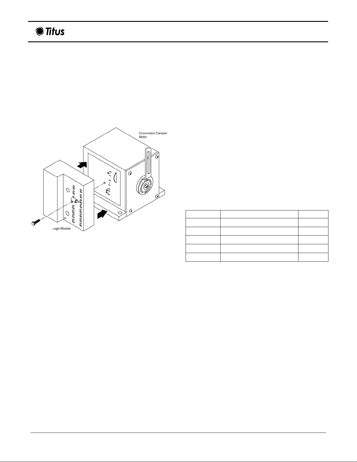
The following segments discuss each system and its
components in detail, with the exception of the ball joints
and pushrods. The setup shown in Figure 1 is logic
module connected to a damper motor in a dedicated
arrangement.
Figure 1. Dedicated Logic Module and Damper Motor
Arrangement
Integrated Economizer System Operation
The purpose of an economizer is to use outdoor air for
cooling, whenever possible, to reduce compressor
operation. An economizer control system includes a
cooling thermostat and a solid-state enthalpy changeover
sensor. This allows it to respond to both dry bulb
temperature and humidity, allowing the use of outdoor air
temperatures for free cooling when humidity is low.
The
economizer functions as a first stage of cooling and
provides maximum economy during the cooling cycle. The
economizer is automatically locked out during heating by
holding the outdoor air damper at the minimum position
setting.
On a call for cooling by the space thermostat, the system
operates as follows:
When the sensed enthalpy of the outdoor air is below the
set point, the outdoor air damper is modulated open (and
return air damper is modulated closed) to maintain
between 50 and 56º Fahrenheit at the
sensor. The second stage cooling uses the mechanical
cooling during the economizer operation.
mixed/discharge air
When the sensed enthalpy of the outdoor air is above the
set point, the outdoor air damper closes to its minimum
position. On a call for cooling from the space thermostat
brings on mechanical cooling.
During the unoccupied period, the damper motor will
spring return the outdoor air damper to full closed position.
Diagnostic Equipment
In addition to either control system package, the following
diagnostic equipment (supplied
beneficial to the installation, verification, and/or
troubleshooting processes.
• 1.2k ohm checkout resistor
• Remote minimum position potentiometer
• Minimum position potentiometer
• Remote bulb control for low ambient lockout
• Board for panel mounting logic module
by others) may be
Three-Position Control System
Components list of the three-position control system is as
follows:
Table 1. Package Contents
Part Code Description Quantity
M8405A Three-position Damper Motor 1
W7459C Logic module 1
C7400A Solid state enthalpy sensor 1
27518 Ball joints 2
27520E 18-inch pushrods 2
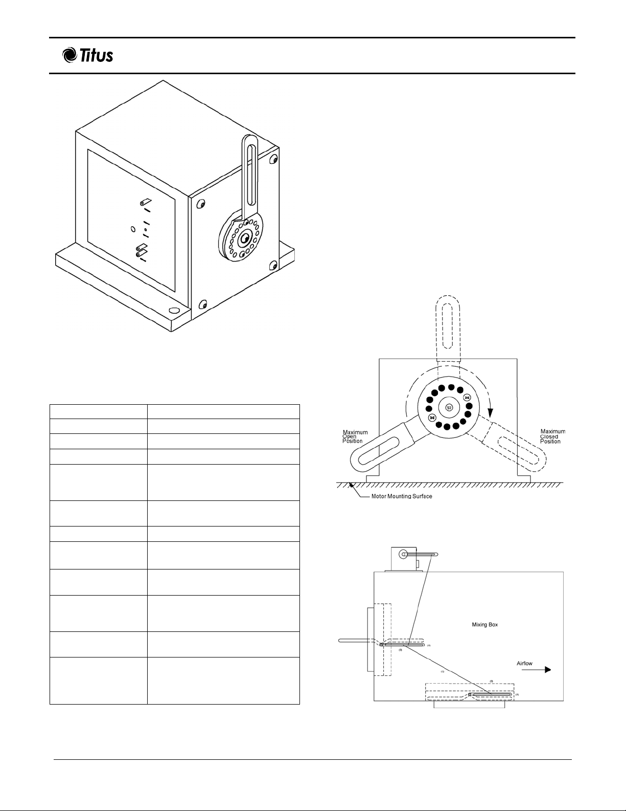
Three-position Damper Motor – M8405A
Spring-return, 25-inch/pound damper motor (actuator)
provides three-position control of economizer systems or
ventilation dampers. Spring returns motor shaft to normal
position on power interruption. The following figure depicts
a damper motor.
Note: Damper motors may be referred to as
actuators.
2 of 15
Page 3
Mixing Box Control Installation Manual
Figure 2. Three-Position Damper Motor
IOM-MBC-00 08-30-04
Installation
When planning the installation, allow ample clearance for
maintenance and service. Ensure the location is protected
from rain and snow. The following steps provide basic
instructions to install a damper motor.
Position damper motor on mixing box where
1.
mounting is desired.
Note: Motor placement may restrict crank arm
rotation. Position motor to allow widest range
of crank arm rotation, see Figure 3.
Use the damper motor holes as guides and
2.
drill four holes into mixing box.
Secure the damper motor to mixing box using
3.
four screws. Figure 4 shows a typical damper
motor to mixing box installation.
Operation Ratings
The following table highlights operational information.
Table 2. Operating Ratings
Operation Rating
Synchronous Normally closed
Power VA 7
Timing (sec.) 90
Stroke
Application
Timing 90 seconds
Voltage and
frequency
Maximum operating
torque
Ambient temperature
rating
Shaft
Approximate
dimensions
Component recognized by Underwriters Laboratories, Inc.
90 degrees, opens counterclockwise as viewed from power
end.
Three-position, with adjustable
minimum position control
24 Vac, 50/60 hertz
25-inch/pound (2.8N-M)
-25° to +125° Fahrenheit (-32° to
+52° Celsius) at 25 percent duty
cycle.
Single-ended drive with crank arm
supplied.
4.5 inches (114 millimeter) high; 5
inches (127 millimeters) wide, and
5.188 inches (132 millimeter)
deep.
Note: Possible 90 degree arm rotation, based on
motor positioning.
Figure 3. Crank Arm Rotation Limits
Figure 4. Typical Damper Motor to Mixing Box
Installation
3 of 15
Page 4

Mixing Box Control Installation Manual
IOM-MBC-00 08-30-04
Settings and Adjustments
Connect 24 Vac to motor at terminals T and X
1.
(Terminal D is not connected).
Adjust thumbwheel on motor for desired minimum
2.
position.
Operation
A single-pole, single-throw (SPST) low-voltage controller
is used to control the three-position Damper Motor.
• Fully open – when controller provides 24 Vac to D
and T, motor is energized and drives fully open.
• Fully closed – when power is removed from
terminals T and D, and the motor spring returns to the
fully closed position.
• Mid-position – when controller provides 24 Vac to T
and X, motor is energized and drives to the adjustable
mid-position (minimum position)
An adjustable minimum position can be reached from
either the fully closed or fully open position. From fully
closed, the motor drives open to the minimum position;
from fully open the motor spring returns to the minimum
position.
.
Verification
Operate the motor through its complete open-close stroke.
If necessary, release one of the previously tightened
linkage connections to prevent damage. Check for proper
operation, ensuring the linkage does not bind and the
motor travels smoothly throughout its fully open and full
closed positions. This motor checkout ensures:
1. The motor operates the load.
2. The motor responds properly to the controller.
There is no binding of the linkage or
3.
at any point of travel.
If motor does not operate properly, check for proper
voltage or mechanical binding in linkage or damper.
If questions arise regarding this product, contact your
distributor or Titus representative.
motor stalling
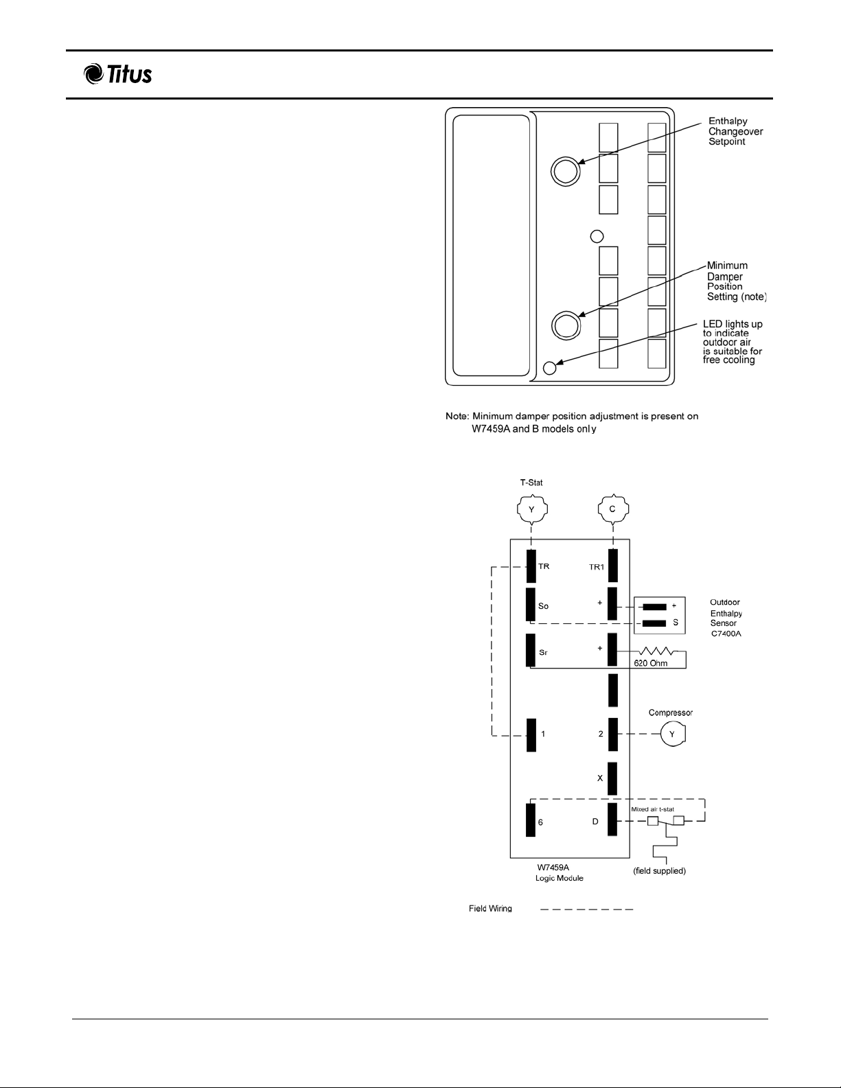
Logic Module – W7459C
The logic module provides control for the damper motor.
Use the enthalpy set point of the logic module to select air
temperature and humidity suitable for free cooling. Figure
5 depicts the logic module.
Remote Minimum Position Control
Remote control of the outdoor air dampers can be used, if
temporary additional ventilation is required. The
potentiometer in the logic module – W7459 controls the
minimum position of the dampers.
Operation
Table 4 provides operational information.
Figure 5. Three-Position Logic Module
Table 4. Operational Ratings
Operation Rating
Operating ambient
temperature
Humidity
Input voltage
Relay contact rating
at 24 Vac
Application
Discharge air
temperature input
Minimum position
potentiometer
adjustment
Terminals for remote
minimum damper
position
Output relays 2 single-pole, dual-throw (spdt)
25º Fahrenheit t
Fahrenheit (32 to +52º Celsius)
5 to 95 percent relative humidity
24 Vac, 50/60 hertz
1.5 A run, 3.5 A inrush
Use with three-position Damper
Motor - M8405A
Single-pole, single-throw (spst)
None
(Minimum position adjustment is
built into Damper Motor M8405)
None
to +125º
p
4 of 15
Page 5
Mixing Box Control Installation Manual
Installation
The logic module mounts on the side of the three-position
damper motor (M8405A). When planning the installation,
allow enough clearance for maintenance and service.
Ensure the location is protected from rain and snow.
1. Align logic module to prongs of the Damper Motor.
2. Press logic module and Damper Motor together.
Secure logic module to damper motor using the
3.
supplied mounting screw.
Settings and Adjustments
The minimum position potentiometer keeps the outdoor air
damper from closing completely during system operation
to provide ventilation. Figure 6 shows potentiometer
adjustment slots. Use a screw
Connect 24 Vac at terminals TR and X (D is not
1.
connected).
Adjust thumbwheel on motor for desired minimum
2.
position.
Wiring
Disconnect power supply before connecting wiring to
prevent electrical shock or equipment. All wiring must
comply with applicable local codes, ordinances, and
regulations. See Figure 7 for wiring diagram depicting the
three-position control system.
driver to make adjustments.
IOM-MBC-00 08-30-04
Figure 6. Enthalpy Set Point Potentiometer (Three-
Position System)
Solid-State Enthalpy Sensor - C7400A
The solid-state enthalpy sensor – the C7400A has a solidstate element that senses temperature and humidity. It
combines solid-state enthalpy changeover control,
minimum damper position potentiometer and compressor
staging relays.
The solid-state enthalpy sensor – C7400A when
the Solid State Economizer Logic Module – W7459 and
three-position damper motor – M8405 helps to position
outdoor and return air dampers in economizer systems.
Figure 8 depicts the solid-state enthalpy sensor.
Use for enthalpy control as follows:
• One sensor in outdoor air for single enthalpy control.
• Two sensors, one in return air and one in outdoor air,
for differential enthalpy control. Contact a Titus
representative, if specifications call for differential
enthalpy control.
The enthalpy set point of the logic module selects the air
temperature and humidity suitable for free cooling.
Operational Ratings
Table 6 highlights operational ratings.
used with
Figure 7. Three-position Control System Circuit
5 of 15
Page 6

Mixing Box Control Installation Manual
Verification and Troubleshooting
The following table provides the actions and responses to
verify the installation of W7459C logic module installed on
an M8405 Actuator.
DISCONNECT POWER SUPPLY BEFORE
CONNECTING WIRING TO PREVENT ELECTRICAL
SHOCK OR EQUIPMENT DAMAGE
Caution: Exercise care when adjusting the
enthalpy changeover and minimum damper
position control. Use a small screwdriver for
these adjustments. Excessive force may damage
the controls.
IOM-MBC-00 08-30-04
DANGER
Figure 8. Solid-State Enthalpy Sensor
Table 6. Operating Ratings
Specific Description
Case
Temperature Sensing
Duct-mounted
Thermistor
Element:
Output Signal
4 to 20 mA current signal;
increases from 4 to 20 mA as
enthalpy decreases
Operating ambient
temperature
Shipping temperature
rating:
Maximum power
-40 to 125° Fahrenheit (-40 to
+52° Celsius)
-40 to 150° Fahrenheit (-40 to
+66° Celsius)
0.45 Vac
consumption
Maximum supply
18 to 24 Vdc
voltage
Electrical connection
Two ¼-inch quick-connect
terminals
Listed by Underwriters Laboratories Inc.
Location and Mounting
The sensor mounts in any position up to 200 feet (61
meters) away from the logic module – W7459C and may
be used for the following operational circumstances.
• Proportional damper control: Attach the logic
module to the Damper Motor’s side.
• Outdoor air sensing: Mount in any orientation where
it is exposed to freely circulating air, but is protected
from rain, snow, and direct sunlight.
• Return air sensing: For differential enthalpy control,
a second C7400A enthalpy sensor can be connected
to the W7459 and mounted in the return air duct.
Note: Contact your Titus representative if
specificat
ions call for differential enthalpy control.
Perform verification and troubleshooting steps in
order.
Table 7. Three-Position Control Verification
and Troubleshooting
esnopseR noitcA
A. Power
Disconnect power at
1.
terminals TR and TR1.
Disconnect wires from
2.
terminals 6, X and D.
3. Jumper TR and 1.
4. Jumper 6 and D.
If connected, remove
5.
C7400A enthalpy sensor
from terminals S
and +.
O
Factory-installed 620-ohm
resistor should be
connected to S
Apply 24 Vac power to
6.
terminals TR and TR1.
and +.
R
LED should be off.
Motor is in closed
position.
Disconnect factory-
7.
installed 620-ohm resistor
from terminals S
B. Enthalpy Simulation
To simulate high and low
1.
and +.
R
LED should be on.
Motor drives toward
open.
enthalpy (single enthalpy
sensor)).
Reconnect factory-
2.
installed 620-ohm resistor
across terminals S
Connect 1.2k ohm
3.
and +.
R
checkout resistor across
terminals S
and +.
O
6 of 15
Page 7

Turn enthalpy set
4.
potentiometer to “A”.
Turn enthalpy set point
5.
potentiometer to “D”.
Disconnect the 1.2k ohm
6.
checkout resistor.
C. Sensor
Reconnect the + lead of
1.
outdoor enthalpy sensor
to the + terminal of
W7459.
Connect a DC multi-meter
2.
or voltmeter between
terminals S
of the W7459
O
and terminal S of the
enthalpy sensor. (Positive
meter lead to terminal S of
enthalpy sensor.)
If using differential
3.
enthalpy, the return air
enthalpy sensor may be
checked by connecting a
DC multi-meter or
voltmeter between
terminal S
of the W7459
R
and terminal S of the
return air enthalpy sensor.
(Position meter lead to
terminal S of return air
enthalpy sensor.
Mixing Box Control Installation Manual
esnopseR noitcA
LED should be on,
indicating low enthalpy.
Motor drives toward
open.
LED should be off,
indicating high enthalpy.
Motor spring returns to
fully closed position.
Multi-meter or voltmeter
should indicate between
3 and 25 mA, if sensor
is operating properly.
If multi-meter or
voltmeter indicates
zero, the sensor may be
wired backwards.
Multi-meter or voltmeter
should indicate between
3 and 25 mA, if sensor
is operating properly.
If multi-meter or
voltmeter indicates
zero, the sensor may be
wired backwards.
IOM-MBC-00 08-30-04
7 of 15
Page 8

Mixing Box Control Installation Manual
Modulating Control System
Package contents of the modulating (enthalpy) system are
as follows:
Table 8. Modulating (Enthalpy) System Package
Part Code Description Quantity
M7415A Modulating damper motor 1
W7459A Logic module 1
C7400A Solid state enthalpy sensor 1
C7150B Sensor 1
27518 Ball joints 2
27520E 18-inch pushrods 2
IOM-MBC-00 08-30-04
Modulating Damper Motor – M7415A
Spring-return, 25-inch/pound damper motor provides
modulating control of economizer systems or ventilation
dampers. Spring returns motor shaft to normal position on
power interruption. Figure 9 depicts a damper motor.
Operation
Tables 9 and 10 provide operating ratings and motor
performance respectively.
A single Damper Motor – M7415 accepts the thermistor
sensor input from the air temperature sensor, mounted in
the discharge or mixed air duct. See Figure 10.
During the occupied period, on a call for cooling, when the
outdoor air temperature is low, the damper motor – M7415
modulates to maintain between 50 and 56° Fahrenheit at
the thermistor.
If the mixed or discharge air temperature is above 56°
Fahrenheit, the damper motor opens to admit additional
outdoor air until the temperature returns to between 50
and 56° Fahrenheit. If the mixed or discharge air
temperature is below 50° Fahrenheit, the damper motor
modulates close, shutting the outdoor air damper until the
temperature returns to between 50 and 56° Fahrenheit.
During the occupied period, the damper will not close past
the minimum position.
If the fully open damper motor cannot satisfy the space
demand, mechanical cooling is sequenced on.
During the unoccupied period, the damper motor overrides
the minimum position setting and drives fully closed. On a
loss of power,
position.
When in heating operation, outdoor air temperature or
enthalpy conditions are high, economizer operation is
locked out, and the damper motor is held at minimum
position.
the damper spring returns to a fully closed
Figure 9. Fully Modulating Damper Motor
Table 9. Operation Ratings
Specification Performance
Stroke
Timing 90 seconds
Voltage and
frequency
Maximum operating
torque
Ambient temperature
rating
Synchronous Normally closed.
Power VA 8
Application
Shaft
Approximate
dimensions
Component recognized by Underwriters Laboratories, Inc.
Fixed 90 degrees, opens counterclockwise as viewed from power
end.
24 Vac, 50/60 hertz
25 inch/pound (2.8N-M)
-25° to +125° Fahrenheit (-32° to
+52° Celsius) at 25 percent duty
cycle.
Modulating, use with thermistor
mixed-air or discharge sensor
(C7150B)
Single-ended drive with crank arm
supplied.
4.5 inches (114 millimeter) high; 5
inches (127 millimeters) wide, and
5.188 inches (132 millimeter)
deep.
8 of 15
Page 9

Mixing Box Control Installation Manual
Figure 10. Economizer Control System Schematic
IOM-MBC-00 08-30-04
Installation
When planning the installation, allow ample clearance for
maintenance and service. Ensure the location is protected
from rain and snow. The following steps provide basic
instructions to install a damper motor.
Position damper motor on mixing box where
1.
mounting is desired. Figure 11 shows possible crank
arm rotation.
Use the damper motor holes as guides and drill four
2.
holes into mixing box.
Secure the damper motor to mixing box using four
3.
screws. Figure 12 shows a typical damper motor to
mixing box installation.
Settings and Adjustments
Once installed, review system requirements and settings.
Then make necessary adjustments using the following
information.
1. Run motor to fully closed position and disconnect 24
Vac from terminals TR and TR1.
2. Connect minimum position potentiometer to terminals P
and P1 (T and T1 are disconnected).
3. Reconnect 24 Vac to terminals TR and TR1 and adjust
potentiometer for desired minimum position.
Note: Possible 90 degree arm rotation, based on motor
positioning.
Figure 11. Crank Arm Rotation Limits
4. When an actuator mounted minimum position
potentiometer is used and a remote potentiometer is
NOT connected in series, utilize jumper terminals P
and P1 on the minimum position potentiometer.
9 of 15
Page 10

Mixing Box Control Installation Manual
IOM-MBC-00 08-30-04
Figure 12. Typical Damper Motor to Mixing Box
Installation
Verification
Operate the motor through its complete open-close stroke.
If necessary, release one of the previously tightened
linkage connections to prevent damage. Check for proper
operation, making sure that the linkage does not bind and
that the motor travels smoothly throughout its fully open
and fully closed positions. This motor checkout ensures:
• The motor operates the load.
• The motor responds properly to the controller.
• There is no binding of the linkage or motor stalling at
any point of travel.
If motor does not operate properly, check for proper
voltage or mechanical binding in linkage or damper.
If questions arise regarding this product, contact your
distributor or Titus representative.
Logic Module – W7459A
The logic module provides the operation control to the
Damper Motor. Use the enthalpy set point of the logic
module to select air temperature and humidity suitable for
free cooling. Figure 13 depicts the logic module.
Remote Minimum Position Control
Remote control of the outdoor air dampers is desirable
when temporary additional ventilation may be required.
The potentiometer in the logic module controls the
minimum position of the dampers.
Operation
Tables 11 and 12 provide operating rating and specific
information.
Figure 13. Fully Modulating Logic Module
Table 11. Operational Ratings
gnitaR noitarepO
Operating ambient
temperature
Humidity
Input voltage 24 Vac, 50/60 hertz
Relay contact rating at 24 Vac 1.5 A run, 3.5 A inrush
Discharge air temperature
input
Minimum position
potentiometer adjustment
Terminals for remote
minimum damper position
Output relays
Application To be used with
25º Fahrenheit tp to
+125º Fahrenheit (32 to
+52º Celsius)
5 to 95 percent relative
humidity
Single-pole, single-throw
(spst)
None
(Minimum position
adjustment is built into
damper motor M7415A)
None
2 Single-pole, doublethrow (spdt)
• Solid-state enthalphy
sensor C7400A
• Modulating damper
motor M7415A
Installation
The logic module mounts on the side of the Modulating
Damper Motor (W7415A). When planning the installation,
allow ample clearance for maintenance and service.
Ensure the location is protected from rain and snow.
Align logic module to prongs of the Damper Motor
1.
and press module and motor together.
Secure logic module to damper motor using the
2.
supplied mounting screw.
10 of 15
Page 11

Mixing Box Control Installation Manual
IOM-MBC-00 08-30-04
Settings and Adjustments
The face of the logic module has two potentiometers with
slots for adjustment. Use a slotted screwdriver to adjust
the potentiometers. Figures 14 and 15 show potentiometer
adjustment slots.
Minimum Damper Position
The minimum position potentiometer keeps the outdoor air
damper from closing completely during system operation
to provide ventilation.
Ensure the factory-installed jumper is in place
1.
across terminals P and P1 (T and T1 are
disconnected).
If remote control of dampers is desired, connect the
2.
remote potentiometer and turn it fully clockwise
before adjusting the minimum position. See Figure
14.
Connect 24 Vac at terminal TR and TR1 and adjust
3.
the potentiometer on the logic module face with a
screwdriver for desired minimum position.
Wiring
Disconnect power supply before connecting wiring to
prevent electrical shock or equipment. All wiring must
comply with applicable local codes, ordinances, and
regulations. Figure 16 shows a modulating circuit.
Figure 14. Enthalpy Set Point Potentiometer Location
Figure 15. Meter Location for Verification and
Troubleshooting
11 of 15
Figure 16. Modulating Control Circuit
Page 12

Mixing Box Control Installation Manual
Solid-State Enthalpy Sensor - C7400A
Use the Solid State Enthalpy Sensor – C7400A and Solid
State Logic Module W7459A with Modulating Damper
Motor - M7415 to proportion outdoor and return air
dampers in economizer systems.
C7400A solid-state element senses temperature and
humidity. Sensor mounts in any position up to 200 feet (61
meters) away from the W7459. Use one sensor in outdoor
air for single enthalpy control. Use two sensors, one in
return air and one in outdoor air, for differential enthalpy
control. W7459A attaches to the damper motor’s side for
proportional control of damper. Combines solid-state
entha
lpy changeover control, minimum damper position
potentiometer and compressor staging relays. To select
air temperature and humidity suitable for free cooling, use
enthalpy set point on W7459.
Table 13 and 14 list application operational specifics,
respectively. Figure 17 depicts a solid-state enthalpy
sensor.
Table 13. Application Specifics
tnemmoC noitacilppA
Sensor Used With C7400A
For use with actuator M7415
Discharge Air Temperature Input
Minimum Position Potentiometer
Adjustment
Terminals for Remote Minimum
Damper Position
Output Relays 2 spdt
Table 14. Operating Specifics
Specific Description
Case Duct-mounted
Temperature
Sensing Element:
Output Signal
Operating ambient
temperature
Shipping
temperature rating:
Maximum power
consumption
Maximum supply
voltage
Electrical connection
Listed by Underwriters Laboratories Inc.
Thermistor
4-20 mA current signal; increases
from 4 mA to 20 mA as enthalpy
decreases
-40 to 125° Fahrenheit (-40 to
+52° Celsius)
-40 to 150° Fahrenheit (-40 to
+66° Celsius)
0.45 Vac
18 to 24 Vdc
Two ¼-inch quick-connect
terminals
Thermistor sensor
C7150B or C7046
YES
YES
IOM-MBC-00 08-30-04
Figure 17. Solid-State Enthalpy Sensor
Location and Mounting
Outdoor air sensing: The Enthalpy Sensor may be
mounted in any orientation where it is exposed to freely
circulating air, but protected from rain, snow, and direct
sunlight.
Return air sensing: For differential enthalpy control, a
second C7400A enthalpy sensor is connected to the
W7459. It is mounted in the return air duct. Contact Titus
if specifications call for differential enthalpy control.
Air Temperature Sensor – C7150B
Use the air temperature sensor – C7150B and the singlezone system – W973 with the damper motor – M7415A to
sense mixed or discharge air in rooftop packaged
conditioning equipment. See Figure 18.
Figure 18. Air Temperature Sensor
air
12 of 15
Page 13

Mixing Box Control Installation Manual
IOM-MBC-00 08-30-04
The sensor consists of thermistor sensor element used in
ventilation duct systems. Negative temperature coefficient
(NTC) causes the resistance to decrease as the sampled air
temperature increases. This resistance change is used to
control the W973 and W7415A. Setting and calibration not
required.
Operation
Table 15 highlights operational ratings of the air temperature
sensor.
Enthalpy Changeover Set Point
With single enthalpy the enthalpy changeover set point is set to
return the outdoor air damper to minimum position when the
enthalpy rises above its set point. The enthalpy set point scale
markings, located on W7459, are
A, B, C, and D in Figure 20.
Table 15. Operation Ratings
Specification Performance
Maximum ambient
temperature
Operating temperature
range
Resistance/ Temperature
(NTC)
Resistance sensitivity per
degree at midrange
Electrical connections
250º Fahrenheit (125º
Celsius)
-30 to 150º Fahrenheit (-34 to
65º Celsius)
300 ohms at 77º Fahrenheit
(25º Celsius)
70 ohms per degree
Fahrenheit
¼-inch quick-connect
terminals
Figure 20. Performance Characteristics for Enthalpy Changeover Settings A, B, C, and D
13 of 15
Page 14

Mixing Box Control Installation Manual
See Figure 20 for the corresponding control point. The
factory-installed 620 ohm jumper must be in place across
terminals + and S
Single M7415 actuator accepts the thermistor sensor input
from C7150B mounted in discharge or mixed air duct. See
Figure 10.
During the occupied period, on a call for cooling, when
outdoor air temperature or enthalpy conditions are low, the
M7415 economizer actuator will proportion to maintain
between 50-56º Fahrenheit at thermistor sensor.
If the mixed or discharge air temperature is above 56º
Fahrenheit, M7415 actuator will open to admit additional
outdoor air until the temperature returns to the 50 to 56º
Fahrenheit
will not close past minimum position.
If the fully open M7415 actuator cannot satisfy the space
demand, mechanical cooling is sequenced on.
During the unoccupied period, the M7415 actuator will
override minimum position setting and drive fully closed.
On a loss of power, the actuator will spring return fully
closed.
When in heating operation, or outdoor air temperature or
enthalpy conditions are high, economizer operation is
locked out, and M7415 actuator is held at minimum
position.
R.
range. During the occupied period, the actuator
IOM-MBC-00 08-30-04
Figure 21. Increasing the Air Temperature Sensor
Setpoint
Discharge Air Temperature Setpoint
Adjustment
The air temperature sensor – C7150B maintains the
discharge or mixed air duct temperature between 50 and
56º Fahrenheit. If the mixed air discharge temperature is
outside the 50 to 56º Fahrenheit range, the damper motor
will proportion open or closed until the temperature returns
to between 50 and 56º Fahrenheit.
This temperature range can be adjusted either up or down
by wiring a resistor in series or parallel with the C7150B
depending on the application. Refer to Figures 21 and 22
for details.
Figure 22. Decreasing the Air Temperature Sensor
Setpoint
14 of 15
Page 15

Mixing Box Control Installation Manual
IOM-MBC-00 08-30-04
Verification and Troubleshooting
The following table provides the actions and responses to
verify the installation of W7459A installed on an M7415
Actuator.
DANGER
DISCONNECT POWER SUPPLY BEFORE
CONNECTING WIRING TO PREVENT ELECTRICAL
SHOCK OR EQUIPMENT DAMAGE
Caution: Exercise care when adjusting the
enthalpy changeover and minimum damper
position control. Use a small screwdriver for
these adjustments. Excessive force may damage
the controls.
Perform verification and troubleshooting steps in
order.
Table 16. Modulating Control Verification
and Troubleshooting
esnopseR noitcA
A. Power
Disconnect power at
1.
terminals TR and TR1.
Disconnect jumper
2.
across P and P1.
3. Jumper TR and 1.
4. Jumper T1 to T.
If connect, remove
5.
C7400A Enthalpy Sensor
from terminals S
Verify Factory-installed
6.
620 ohm resistor is
connected to S
Apply 24 Vac power to
7.
terminals TR and TR1
Disconnect factory-
8.
installed 620 ohm
resistor from terminals S
and +.
B. Enthalpy Simulation
Reconnect factory-
1.
installed 620-ohm
resistor across terminals
S
and +.
R
Connect 1.2k ohm
2.
checkout resistor across
terminals S
R
and +.
O
and +.
O
and +.
LED should be off.
Motor is in closed
position.
LED should be on,
indicating low enthalpy.
R
Motor drives toward
open.
esnopseR noitcA
Set enthalpy set point
3.
potentiometer to “A”.
LED should come on,
indicating low enthalpy.
Motor drives toward
open.
Set enthalpy set point
4.
potentiometer to “D”.
LED should go off,
indicating high enthalpy.
Motor drives toward
closed.
C. Sensor
Reconnect the + lead of
1.
outdoor enthalpy sensor
to the + terminal of
W7459.
Connect a DC multi-
2.
meter or voltmeter
between terminals S
the W7459 and terminal
S of the enthalpy sensor.
(Positive meter lead to
terminal S of enthalpy
sensor.)
If using differential
3.
enthalpy, the return air
enthalpy sensor may be
checked by connecting a
DC multi-meter or
voltmeter between
terminal S
of the W7459
R
and terminal S of the
O
Multi-meter or voltmeter
should indicate between
of
3 and 25 mA, if sensor
is operating properly.
If multi-meter or
voltmeter indicates
zero, the sensor may be
wired backwards.
Multi-meter or voltmeter
should indicate between
3 and 25 mA, if sensor
is operating properly.
If multi-meter or
voltmeter indicates
zero, the sensor may be
wired backwards.
return air enthalpy
sensor. (Position meter
lead to terminal S of
return air enthalpy
sensor.
Abbreviations
The following table lists the abbreviations found within this
document.
Abbrev. Term
A Ampere
BTU British Thermal Units
DC Direct Current
LED Light Emitting Diode
mA Milliampere
NTC Negative temperature coefficient
RH Relative Humidity
spdt Single-pole, double -throw
spst Single-pole, single-throw
Vac Volts Alternating Current
Vdc Volts Direct Current
15 of 15
 Loading...