

Page 1
Titus Proportional Lynergy
W/ Discharge Temperature Limit
Start-Up, Operation and Service Instructions
SAFETY NOTE
Air-handling equipment will provide safe and reliable service when operated within design specifications. The equipment
should be operated and serviced only by authorized personnel who have a thorough knowledge of system operation, safety
devices, and emergency procedures. Good judgment should be used in applying any manufacturer’s instructions to avoid injury
to personnel or damage to equipment and property.
WARNING
power is not disconnected. Electrical shock and personal injury could result.
WARNING
control box and/or heat sinks may be hot.
LineaHeat is an electronic, time proportional electric heat system. The heat output of the heater is modulated utilizing quiet,
rapid performing solid state relays. The relays are switched off and on to allow the heating of electrical resistance elements.
The proportion of time the relay is on dictates the proportion of maximum heat the electric heater can produce. The solid state
relays are switched off and on by a supplied Electric Heat Module (EHM). The EHM accepts an input signal from the terminal
unit controller or thermostat for the amount of heat desired. The EHM can accept a variety of different input signals when
interfacing with controls. The type of input the EHM will accept is modified by changing the position of one or two jumpers
easily accessible on the board.
The LineaHeat is available with an optional discharge temperature sensor. When used with the discharge sensor option, the
LineaHeat will modulate outgoing temperature from the unit between the maximum temperature setting and initial temperature
of incoming air before heating began. The discharge temperature set point is easily adjusted in the field by rotating the
temperature dial on the EHM. The EHM will not allow temperatures over the set point so as to prevent overheating,
stratification, and energy waste from heated air lost through overhead returns.
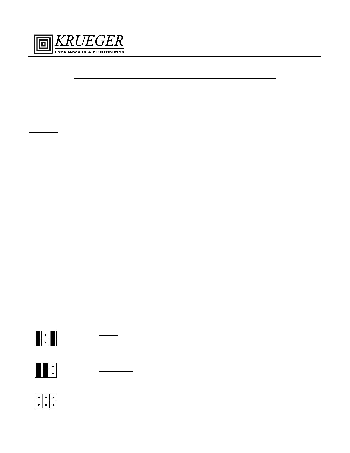
INPUT SETTING. The LineaHeat board is capable of being controlled and operated 7 different ways. The units are ordered
with an LXY code, where “X” is coded for unit power and “Y” is coded for the application. This “Y” application can be
changed in the field. The application desired is chosen by placement of jumpers in the corner of board (See Drawing 1 on page
2). Jumper settings below are representative of pins at bottom left of control board as shown in drawing. Wiring diagrams for
each are on pages 5 & 6.
: Disconnect all power to the unit before performing maintenance or service. Unit may automatically start if
: Units with LineaHeat use Solid State relays, which generate heat when used. The temperature of the
OVERVIEW
START-UP
LX1) On/Off: This application accepts one 24 Vac input at “Inc” to step the heater output from
OFF to 100% heater kW rating. The signal may be pulsed off and on over a small time
period to provide proportional heat. For example, a signal that is on for 4.5 seconds every
10 seconds would produce 45% of the heater’s kW rating.
LX2) 2 Stage (2Stg): This two stage application accepts two 24 Vac inputs to step the heater
LX3) 0-10V: This application accepts a 0-10 Vdc (0-20mA) signal to modulate the heater
output from off to 50% or 100% heater kW rating. A signal to “Inc” is 50% and a signal
to “Dec” is 100%
output. The output is proportional to input signal (i.e., 4.5 volts sets the heater to 45% of
kW rating).
1
Page 2
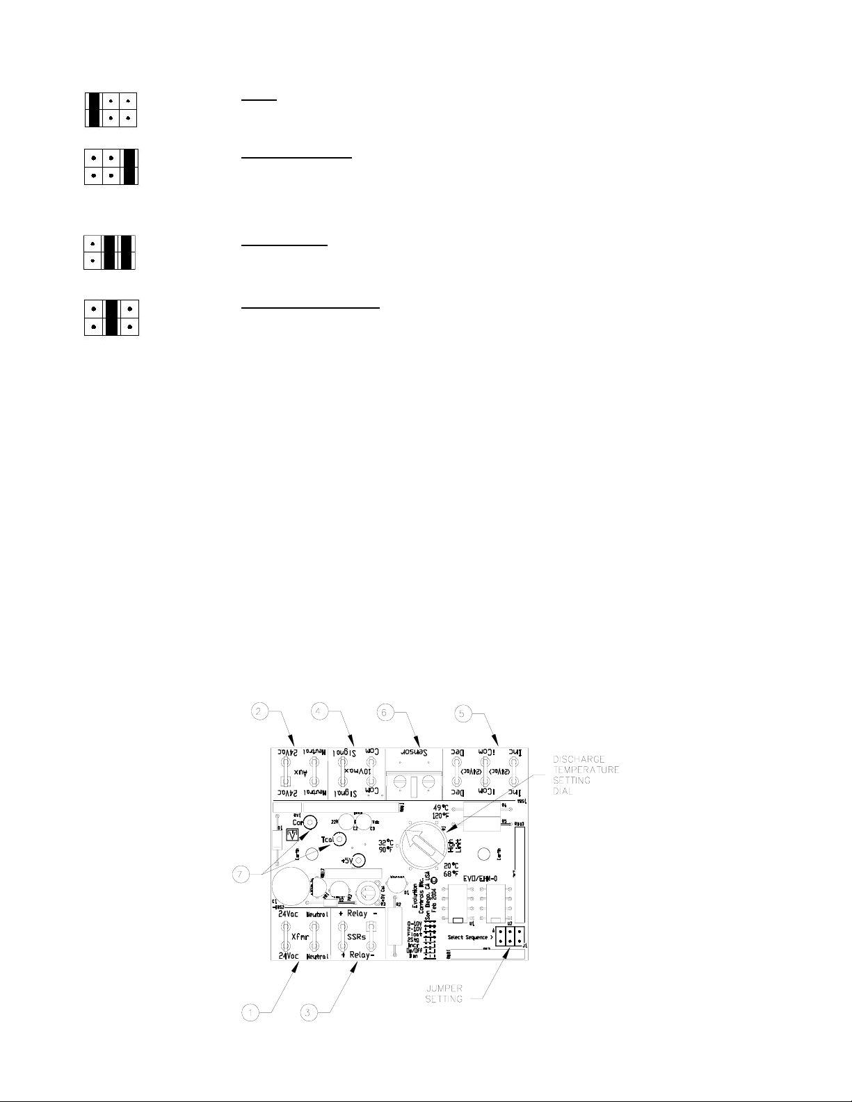
LX4) 2-10V: This application accepts a 2-10 Vdc (4-20 mA) signal to modulate the heater
output. The output is proportional to input voltage above 2 volts (i.e., 4.5 volts sets the
heater to 25% of kW rating).
LX5) Incremental (Incr): This application accepts one 24 Vac input to modulate heater output.
An increase signal will increase the heater output from 0% to 100% over a 4 minute 15
second interval, staying at 100% afterward. When the signal is removed, the heater output
will decrease to 0% over the same time period. This application mirrors a Normally
Closed hot water valve.
LX6) Bininary (Bin): This application accepts two 24 Vac inputs to step the heater from off to
33%, 67%, or 100% of the heater’s kW rating. A signal to “Inc” is 33%, a signal to “Dec”
is 67%, and a signal to both is 100%.
LX7) 3 Point Floating (Float)
: This floating input application accepts two 24 Vac inputs to
increase or decrease the heater output. As the increase signal is sent, the heater output will
increase from 0% to 100% over a 2 minute 15 second interval. If the increase signal is
removed, or decrease signal is also added, the heater output will stay constant at present
point. When only the decrease signal is received, the heater output will decline from the
present level to 0% over the same time period. This application mirrors a Three-Point
floating hot water valve.
WIRING. The EHM control board is powered by 24Vac (1) from the transformer in the electric heater. The EHM has
auxiliary 24Vac outputs (2) that can be used to power the unit’s electrical controls. Next to the “Xfmr” inputs are the “+” and
“-“ Relay connections (3) that control the solid state relays by sending pulses of ~25Vdc.
There are two terminations to use for dc Volt control (4) of the electric heat (applications LX3 and LX4 from above). These
are polar sensitive. The “+” signal from the controller must be connected to “Signal” on the EHM Control Board. The “-“
from the controller must be connected to “Com” next to “Signal (Note: NOT “iCom”). A termination to “-“ is possible, but not
necessary to measure mA signals to the board.
There are three terminations for 24 Vac control (5) of the electric heat (applications LX1, LX2, LX5, LX6, and LX7 from
above). “Inc” is for the increase signal in applications LX5 and LX7, as well as the first stage heat signal in applications LX1,
LX2, and LX6. “Dec” is for the decrease signal in application LX7, as well as the second stage heat signal in applications LX2
and LX6. A connection to “iCom” is necessary for all of these 24 Vac applications. If the unit’s controller does not have a
Common output, a jumper to the correct “Aux” terminal can be used. If the unit controller outputs the “24Vac” side from it’s
input power, a jumper should be made from “Neutral” to “iCom” (See sample diagram on page 7). If the unit controller
outputs the “Neutral” side of it’s input power, a jumper should be made from “24Vac” to “iCom”.
2
Page 3
DISCHARGE TEMPERATURE SET POINT. LineaHeat comes with a discharge temperature set point (DTS) option. This
option allows a maximum temperature to be set at the board to prevent overheating of discharge air. When the unit receives a
signal to start heating, the board will take an initial temperature reading and modulate heat from that point to the maximum
temperature. For example, if a thermostat requires only a 10% heating output of air that was initially 60°F and has a maximum
temperature setting of 90°F, the EHM will modulate the heater’s output temperature to 63°F (the additional 3 degrees coming
from (90-60)*10%). This allows heaters to be sized for morning warm up in the winter and still comfortably operate on those
days when the inlet temperatures are slightly warmer.
The discharge temperature sensor comes with a 9’ cable for mounting in the downstream ductwork. The sensor should be
mounted a minimum of 36” from the discharge of the unit and be vertically centered in the ductwork. The sensor can be
mounted by drilling a 1/2” hole into the ductwork, inserting the sensor, and securing it with 2 sheet metal screws. The sensor is
6” long, and the tip should not touch any part of the ductwork.
Neither the jumper settings nor the controls wiring needs to be changed when this option is ordered. The EHM control board
will detect if a sensor has been connected, and it will adjust the control function accordingly. The sensor wires are connected
to the screw terminals at the “Sensor” (6) location on the EHM. The connection at this termination is not polar sensitive and
the two wires may be switched with no effect.
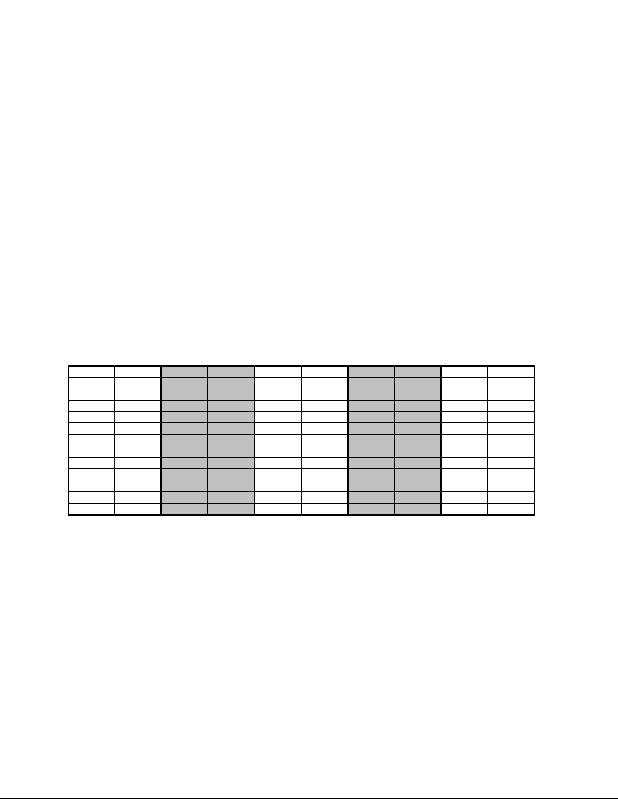
The desired discharge temperature is set by rotating the discharge temperature set point dial arrow to the maximum outlet
temperature desired. To fine tune the discharge temperature set point, connect the positive and negative leads of a multimeter
to “Tcal” and “Com” (7), respectively, on the EHM. Then place a jumper between the two screw heads on the sensor
termination. Rotate the discharge temperature set point dial until the desired voltage per temperature is obtained. After the
voltage is obtained, the EHM board must be reset. To reset the board, remove the jumpers and then place back in correct
position.
TEMP dc VOLT TEMP dc VOLT TEMP dc VOLT TEMP dc VOLT TEMP dc VOLT
68 0.00 80 0.58 90 0.95 100 1.23 110 1.44
69 0.05 81 0.62 91 0.98 101 1.25 111 1.46
70 0.10 82 0.66 92 1.01 102 1.27 112 1.48
71 0.15 83 0.70 93 1.04 103 1.30 113 1.50
72 0.20 84 0.74 94 1.07 104 1.32 114 1.51
73 0.26 85 0.77 95 1.10 105 1.34 115 1.53
74 0.30 86 0.81 96 1.12 106 1.36 116 1.55
75 0.35 87 0.85 97 1.15 107 1.38 117 1.56
76 0.40 88 0.88 98 1.18 108 1.40 118 1.58
77 0.44 89 0.91 99 1.20 109 1.42 119 1.60
78 0.49 120 1.61
79 0.53
It should be noted that ASHRAE Fundamentals Handbook (Chapter 31) states that discharging air at a temperature more than
15°F above the room (90°F in a 75°F room) will likely result in significant unwanted air temperature stratification.
It is recommended that heater output is ramped or staged when switching from cooling to heating modes. On initial call for
maximum or near maximum heat, from cooling mode, the heater may overshoot the desired temperature by up to 20°F for 10
to 20 seconds (on oversized heaters). As the EHM begins modulating heater output, the discharge temperature will quickly
drop to the desired set point. Temperatures within ±2°F of desired set point are reached within 90 seconds with oversized
heaters.
3
Page 4

TROUBLESHOOTING
Problem: No Heat when called for.
1) Confirm the jumper setting is correct for the input given.
a) If the controls are outputting Vdc, the jumper should be set as shown on page 1 for applications LX3, and
LX4.
b) If the controls are outputting 24Vac, the jumper setting should be set as shown on pages 1 & 2 for
applications LX1, LX2, LX5, LX6, & LX7. (Also see diagrams on page 6 & 7)
2) Check that wiring to the EHM is correct.
a) If using applications LX3 and LX4, confirm the positive Vdc connection is wired to the “Signal” terminal,
and the negative Vdc connection is wired to the “Com“ terminal.
b) If using 24Vac, confirm the wires are terminated correctly at (5) with a connection at “iCom”. If an “Aux”
terminal (2) on the EHM has been jumpered to “iCom”, make sure that the opposite 24Vac input is what is
outputted at the controls (See page 7 for one example).
3) Check that airflow is above minimum. Terminal units with electric heat come with pressure switches to insure that
heater elements have airflow over them. See catalog for minimum airflow required for specific size terminal units.
Fan boxes must have minimum downstream static of 0.2”.
4) Check that discharge temperature setpoint is not below the airflow temperature.
5) Check Relay wiring. Solid state relays are polarity sensitive. The wire from “+” on the EHM control board should be
terminated on “+3” VDC terminal of the relay. The wire from “-“ on the EHM control board should be terminated on
“4-“ VDC terminal of the relay. If there are two relays used in the heater, the relays are daisy chained from “4-“ to
“+3” together (See page 7 for one example).
Problem: Discharge Temperature not at Temperature Setting.
1) Check that wires from sensor are stripped and terminated in EHM control terminals.
2) Check that wires from controls are terminated at the correct point on EHM board. Inrease or stage 1 signal should be
terminated at “Inc”. Decrease or stage 2 signal should be terminated at “Dec”.
3) Check volt setting. Use chart and procedure on page 3.
4) Check sensor placement. Make sure that sensor is well placed vertically in ductwork and at least 36” from discharge.
Sensor tip should not touch inside of ductwork.
5) Try staging or ramping of output on oversized heaters. When controls call for full heat from cooling mode, if heaters
are too large and heating times are small, the heater output may be over setpoint. Staging or ramping of output over a
60 second interval will provide smooth transition. If only one output of heat is available from controls, application
LX5 will proportionally ramp heat output from 0 to 100% over a 2 minute 15 second span.
4
Page 5

ENCLOSURE
VOLTAGE
HEATER
APPLICATION
LX3
(0-20mA)
0-10 Vdc
TO HI
ENCLOSURE
VOLTAGE
TO HI
APPLICATION
LX1
HEATER
ON/OFF
SEQUENCE
BLACK #18
DESIGNATED
FOR CONTROL
YEL #18
BLUE #18
RED #18
ON PINS
JUMPERS
24Vac
Neutral
Relay +
Relay -
Xfmr
Neutral24Vac
Neutral24Vac
+
+
Relay
Relay
SSRs
-
-
On/Off
Float
Incr
0-10V
2Stg
2-10V
Bin
Select Sequence>
Com
Tcal
32°C
90°F
120°F
49°C
20°C
68°F
High
Limit
EVO/EHM-
Earth
PLACE
SENSOR
Neutral 24Vac
Signal
Com
Dec
iCom
Inc
DISCHARGE
TEMP
Aux
10Vmax
(24Vac)
(24Vac)
OPTIONAL
24VacNeutral
Neutral
iCOM
Signal
INC
Red
Black
Sensor Com
Dec
iCom
Inc
24Vac
BLUE #18
BLACK #18
RED #18
ANALOG OUT POS
ANALOG OUT NEG
CONTROLLER
24VAC INPUT
YELLOW #18
SEQUENCE
BLACK #18
DESIGNATED
FOR CONTROL
ON PINS
YEL #18
BLUE #18
RED #18
JUMPERS
24Vac
Neutral
Relay +
Relay -
Xfmr
Neutral24Vac
Neutral24Vac
+
+
Relay
Relay
SSRs
-
-
On/Off
Float
Incr
0-10V
2Stg
2-10V
Bin
Select Sequence>
Com
Tcal
32°C
90°F
120°F
49°C
20°C
68°F
High
Limit
EVO/EHM-
Earth
PLACE
Aux
Neutral 24Vac
Signal
10Vmax
Com
Dec
(24Vac)
iCom
(24Vac)
Inc
OUTPUT
24Vac
24VacNeutral
Neutral
Signal
Sensor Com
Dec
iCOM
iCom
INC
Inc
HEATER
CONTROLS
YELLOW #18
BLUE #18
Black
POWER
CONTROLS
TO
BLACK #18
RED #18
COMMON
CONTROLS
Red
DISCHARGE
OPTIONAL
SENSOR
TEMP
ENCLOSURE
VOLTAGE
HEATER
APPLICATION
TO HI
LX4
(4-20mA)
2-10 Vdc
YEL #18
BLUE #18
RED #18
BLACK #18
24Vac
Neutral
Relay +
Relay -
Xfmr
Neutral24Vac
Neutral24Vac
+
+
Relay
Relay
SSRs
-
-
On/Off
Float
Incr
0-10V
2Stg
2-10V
Bin
Select Sequence>
Com
Tcal
32°C
90°F
120°F
49°C
20°C
68°F
High
Limit
EVO/EHM-
Earth
24Vac
24VacNeutral
Aux
Neutral
Neutral 24Vac
iCOM
Signal
Signal
INC
10Vmax
Com
Red
Black
Sensor Com
Dec
Dec
(24Vac)
iCom
iCom
(24Vac)
Inc
Inc
BLACK #18
RED #18
ANALOG OUT POS
ANALOG OUT NEG
YELLOW #18
BLUE #18
24VAC INPUT
ENCLOSURE
VOLTAGE
TO HI
APPLICATION
LX2
HEATER
2 STAGE
YEL #18
BLUE #18
RED #18
BLACK #18
24Vac
Neutral
Relay +
Relay -
Xfmr
Neutral24Vac
Neutral24Vac
+
+
Relay
Relay
SSRs
-
-
On/Off
Float
Incr
0-10V
2Stg
2-10V
Bin
Select Sequence>
Com
Tcal
32°C
90°F
120°F
49°C
20°C
68°F
High
Limit
EVO/EHM-
Earth
24Vac
24VacNeutral
Aux
Neutral
Neutral 24Vac
Signal
Signal
10Vmax
Com
Red
Black
Sensor Com
Dec
Dec
Dec
iCOM
(24Vac)
iCom
iCom
(24Vac)
INC
Inc
Inc
WHITE #18
BLACK #18
RED #18
POWER
YELLOW #18
BLUE #18
CONTROLS
TO
SEQUENCE
DESIGNATED
FOR CONTROL
PLACE
ON PINS
JUMPERS
DISCHARGE
OPTIONAL
SENSOR
TEMP
CONTROLLER
SEQUENCE
FOR CONTROL
ON PINS
JUMPERS
COMMON
2ND STAGE
1ST STAGE
DISCHARGE
OPTIONAL
SENSOR
TEMP
PLACE
DESIGNATED
CONTROLLER
5
Page 6

ENCLOSURE
VOLTAGE
LX7
FLOATING
HEATER
(Float)
APPLICATION
THREE POINT
TO HI
ENCLOSURE
VOLTAGE
(Incr)
INCREMENTAL
LX5
HEATER
APPLICATION
TO HI
SEQUENCE
BLACK #18
DESIGNATED
FOR CONTROL
YEL #18
BLUE #18
RED #18
ON PINS
JUMPERS
24Vac
Neutral
Relay +
Relay -
Xfmr
Neutral24Vac
Neutral24Vac
+
+
Relay
Relay
SSRs
-
-
On/Off
Float
Incr
0-10V
2Stg
2-10V
Bin
Select Sequence>
Com
Tcal
32°C
90°F
120°F
49°C
20°C
68°F
High
Limit
EVO/EHM-
Earth
PLACE
24Vac
24VacNeutral
Aux
Neutral
Neutral 24Vac
Signal
Signal
10Vmax
Com
Red
Black
Dec
Dec
Dec Sensor Com
iCOM
(24Vac)
iCom
(24Vac)
Inc
iComInc
INCREASE
INC
HEATER
BLACK #18
RED #18
DECREASE
COMMON
BLUE #18
POWER
WHITE #18
CONTROLS
HEATER
DISCHARGE
SENSOR
TEMP
TO
OPTIONAL
YELLOW #18
SEQUENCE
BLACK #18
DESIGNATED
FOR CONTROL
YEL #18
BLUE #18
RED #18
ON PINS
JUMPERS
24Vac
Neutral
Relay +
Relay -
Xfmr
Neutral24Vac
Neutral24Vac
+
+
Relay
Relay
SSRs
-
-
On/Off
Float
Incr
0-10V
2Stg
2-10V
Bin
Select Sequence>
Com
Tcal
32°C
90°F
120°F
49°C
20°C
68°F
High
Limit
EVO/EHM-
Earth
PLACE
24Vac
24VacNeutral
Aux
Neutral
Neutral 24Vac
Signal
Signal
10Vmax
Com
Sensor Com
Dec
Dec
iCOM
(24Vac)
iCom
iCom
(24Vac)
INC
Inc
Inc
HEATER
OUTPUT
Black
BLACK #18
RED #18
CONTROLS
COMMON
Red
CONTROLS
SENSOR
BLUE #18
POWER
CONTROLS
DISCHARGE
TEMP
YELLOW #18
TO
OPTIONAL
CONTROLLER
ENCLOSURE
VOLTAGE
HEATER
APPLICATION
TO HI
LX6
BINARY 3 STAGE
(Bin)
YEL #18
BLUE #18
RED #18
BLACK #18
24Vac
Neutral
Relay +
Relay -
Xfmr
Neutral24Vac
Neutral24Vac
+
+
Relay
Relay
SSRs
-
-
On/Off
Float
Incr
0-10V
2Stg
2-10V
Bin
Select Sequence>
Com
Tcal
32°C
90°F
120°F
49°C
20°C
68°F
High
Limit
EVO/EHM-
Earth
24Vac
24VacNeutral
Aux
Neutral
Neutral 24Vac
Signal
Signal
10Vmax
Com
Red
Black
Sensor Com
Dec
Dec
Dec
iCOM
(24Vac)
iCom
iCom
(24Vac)
INC
Inc
Inc
WHITE #18
BLACK #18
RED #18
POWER
YELLOW #18
BLUE #18
CONTROLS
TO
PLACE
DESIGNATED
FOR CONTROL
ON PINS
SEQUENCE
JUMPERS
COMMON
2ND STAGE
1ST STAGE
DISCHARGE
OPTIONAL
SENSOR
TEMP
CONTROLLER
6
Page 7

SAMPLE LINEAHEAT SCHEMATIC
MOVE JUMPER ON LINEAHEAT FROM
"NEUTRAL", TO "24VAC".
24Vac
Xfmr
Neutral
Neutral24Vac
+
+
Relay
Relay
INTERNALLY SWITCH "24VAC COM",
TO THE OUTPUTS. FOR CONTROLS THAT
CONTROLS WITH NO COMMON OUTPUT
THAT INTERNALLY SWITCHES "24VAC+"
DRAWING SHOWS WIRING FOR
SSRs
-
-
On/Off
Float
Incr
2Stg
Bin
Select Sequence>
CONTROLLER
Com
24VacNeutral
24Vac
Aux
Neutral
Tcal
Signal
Signal
10Vmax
32°C
90°F
2-10V
0-10V
UNIT
Com
Sensor Com
120°F
49°C
20°C
68°F
High
Limit
Dec
EVO/EHM-
Earth
TER M IN A L
Dec
(24Vac)
iCom
iCom
(24Vac)
Inc
Inc
7
 Loading...