

Page 1
Installation, Operation and
TU-LSC-IOM-1.0
Maintenance
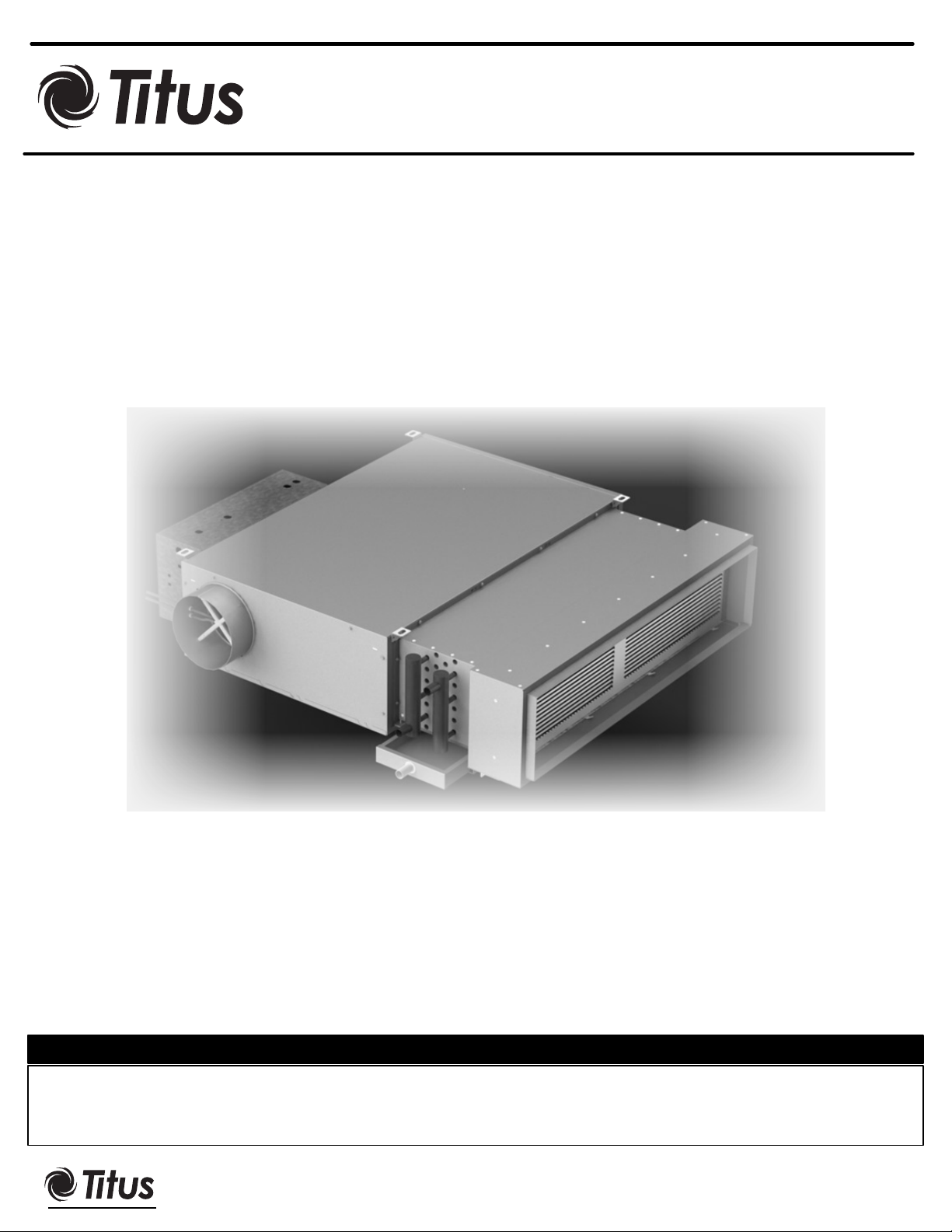
Low Profile, Series Fan Powered Terminal Unit with
Sensible Cooling Coil
(400 to 1800 cfm)
11-16-12
Model: LSC RevA
SAFETY WARNING
Only qualified personnel should install and service the equipment. The installation, starting up, and servicing of heating, ventilating,
and air-conditioning equipment can be hazardous and requires specific knowledge and training. Improperly installed, adjusted or
altered equipment by an unqualified person could result in death or serious injury. When working on the equipment, observe all
precautions in the literature and on the tags, stickers, and labels that are attached to the equipm
This IOM is meant to demonstrate general dimensions and information of this product. The drawings are not meant to detail every aspect of the product. Drawings are not to scale.
®
605 Shiloh Road • Plano, Texas 75074• 972-212-4800
All rights reserved. No part of this work may be reproduced or transmitted in any form or any means, electronic or mechanical, including photocopying and recording, or by any information storage retrieval system without permission in writing from Air Distribution Technologies
Titus reserves the right to make changes without written notice.
ent.
Page 2
TU-LSC-IOM
Warnings, Cautions and Notices. Note that warnings,
cautions and notices appear at appropriate intervals
throughout this manual. Warnings are provide to alert
installing contractors to potential hazards that could result in
death or personal injury. Cautions are designed to alert
personnel to hazardous situations that could result in
personal injury, while notices indicate a situation that could
result in equipment or property-damage-only accidents.
Your personal safety and the proper operation of this
machine depend upon the strict observance of these
precautions. Read this manual thoroughly before operating
or servicing this unit.
ATTENTION: Warnings, Cautions and Notices appear at
appropriate sections throughout this literature. Read these
carefully:
WARNING Indicates a potentially hazardous situation
which, if not avoided, could result in death or serious injury.
CAUTION Indicates a potentially hazardous situation which,
if not avoided, could result in minor or moderate injury. It
could also be used to alert against unsafe practices.
NOTICE: Indicates a situation that could result in
equipment or property-damage only
WARNING
Proper Field Wiring and Grounding Required!
All field wiring MUST be performed by qualified
personnel. Improperly installed and grounded field
wiring poses FIRE and ELECTROCUTION hazards. To
avoid these hazards, you MUST follow requirements
for field wiring installation and grounding as described
in NEC and your local/state electrical codes. Failure to
follow code could result in death or serious injury.
WARNING
Personal Protective Equipment (PPE) Required!
Installing/servicing this unit could result in exposure
to electrical, mechanical and chemical hazards.
Before installing/servicing this unit, technicians
MUST put on all Personal Protective Equipment
(PPE) recommended for the work being
undertaken. ALWAYS refer to appropriate MSDS
sheets and OSHA guidelines for proper PPE.
When working with or around hazardous
chemicals, ALWAYS refer to the appropriate MSDS
sheets and OSHA guidelines for information on
allowable personal exposure levels, proper
respiratory protection and handling
recommendations.
If there is a risk of arc or flash, technicians MUST
put on all Personal Protective Equipment (PPE) in
accordance with NFPA 70E or other countryspecific requirements for arc flash protection,
PRIOR to servicing the unit.
Failure to follow recommendations could result in
death or serious injury.
2
Page 3

Warnings, Cautions and Notices 2
Model Number Descriptions 4
General Information 6
Pre-Installation
Receiving and Handling 7
Shipping Package 7
Receiving Check List 7
Jobsite Storage 7
Installation Preparation 7
Service Access 8
Pre-Installation Check List 8
Components Data 9
Unit Dimensions 10
Coil Flange Connections 11
Weights 12
Water Coil Pipe Connections 13
Installation Mechanical
Duct Connections 14
Duct Work Recommendations 14
Hydronic Piping Consideration 14
Condensate Drain Connection 14
External Insulation Requirements 15
TU-LSC-IOM
Installation General - Hanging the Unit 16
Installation Check List 17
Installation Electric
Unit Wiring Diagrams 18
Supply Power Supply 18
Electric Heater Min-Max KW – Unit size 3 19
Electric Heater Min-Max KW – Unit size 4 20
ECM Motor Overview and Setup
Overview 21
General Information 21
ECM Motor Fan Flow Adjustment 21
Manual PWM Signal Interface Board 22
Operation 22
Remote PWM Signal Interface Board 22
Jumper Setup 23
Input / Output Control Signals 23
Remote Control Air Balance 23
Manual Air Balance 23
Pre-Startup Checklist 24
Maintenance
Maintenance Procedures 25
Air Filter 25
Inspecting and Cleaning Condensate Pans 25
Coil Maintenance 25
Inspecting and Cleaning Coils 25
Hydronic Coil Cleaning Procedures 26
Winterizing the Coil 26
Replacing Motors 26
Periodic Maintenance Check List 26
3
Page 4

TU-LSC-IOM
LSC – Low Profile Series Fan Powered Terminal Unit
with Cooling Coil
Following is a complete description of the LSC model
number. Each digit in the model has a corresponding
code that identifies specific unit options.
Digit 1, 2, 3, 4 – Unit Type
LSC = Basic Unit
LSCX = Special Unit
Digit 5, 6 – Cabinet Size
03 = Unit size 3
04 = Unit size 4
XX = Special
Digit 7 – Cabinet Configuration
R = Right Hand Control Enclosure
L = Left Hand Control Enclosure
X = Special
Digit 8, 9 – Cabinet Material
2G = 20Ga Galvanized Steel Cabinet
XX = Special
Digit 10 – Cabinet Liner
J = EcoShield Matte faced ½”
L = EcoShield Foil Faced ½”
0 = Fiberglass Dual Density ½”
3 = fiberglass Foil Faced ½”
9 = FiberFree ½”
X = Special
Digit 11 – ECM Motor Power Supply
1 = ECM motor 120V/1Ph/60Hz
2 = ECM Motor 208V/1Ph/60Hz
3 = ECM Motor 277V/1Ph/60Hz
X = Special
Digit 26 – Airflow Measuring Sensor
0= None
3= Aerocross
X = Special
Digit 27,28,29 – Cooling and Heating coils
200 = 2 Rows Cooling only coil
201 = 2 Rows Cool + 1 Row Heating coil
400 = 4 Rows Cooling only coil
401 = 4 Rows Cool + 1 Row Heating coil
XXX = Special
Digit 30, 31 – Filter (Optional Accessories)
00 = None
F1 = 1 x 1" Filter – NOT Ducted
F2 = 1 x 1" Filter + Spare Filter - NOT Ducted
F3 = 1 x 2" Filter – NOT Ducted
F4 = 1 x 2" Filter + Spare Filter - NOT Ducted
F5 = 1 x 1" Filter – Ducted
F6 = 1 x 1" Filter + Spare Filter - Ducted
F7 = 1 x 2" Filter – Ducted
F8 = 1 x 2" Filter + Spare Filter – Ducted
XX = Special
Digit 32,33 – Motor Fuses ( Optional Accessories)
00 = None
MF = Motor Fuses
XX = Special
Digit 34,35 –Unit Accessories
(Optional Accessories)
0= None
B = Hanger Brackets
Y = Slip & Drive Adaptor (Fan Discharge)
X = Special
Digit 36,37,38,39 – Controller
(Optional Accessories)
0000 = None
XXXX = Special
Digit 12 – Motor Control
M = Manual Control Board
R = Remote PWM Control
X = Special
Digit 13 – Primary Inlet Size
4 = 4" Diameter
6 = 6" Diameter
8 = 8" Diameter
22 = 16" x 8" Rectangular
XX = Special
Digit 14,15,16,17 – Minimum Primary Airflow (cfm)
Digit 18,19,20,21 – Maximum Primary Airflow (cfm)
Digit 22,23,24,25 – Fan Airflow (cfm)
Digit 40,41,42,43 – Damper Actuator (
Optional Accessories)
0000 = None
DT01 = Electronic Damper Actuator – Titus
XXXX = Special
Digit 44,45,46,47 – Controls Optional Accessories
0= None
D = Disconnect Switch (Non Fused)
E = Control Enclosure
G = Dust Tight Control Enclosure
T = Dust Tight Disconnect Switch
X = Special
4
Page 5

TU-LSC-IOM
Digit 48,49,50 – Electric Heaters Type
0= None
E21 = 208V/1Ph 1Stage
E22 = 208V/1Ph 2 Stages
E23 = 208V/1Ph 3 Stages
E31 = 240V/1Ph 1Stage
E32 = 240V/1Ph 2 Stages
E33 = 240V/1Ph 3 Stages
E41 = 277V/1Ph 1Stage
E42 = 277V/1Ph 2 Stages
E43 = 277V/1Ph 3 Stages
E61 = 208V/3Ph 1Stage
E62 = 208V/3Ph 2 Stages
E63 = 208V/3Ph 3 Stages
E91 = 480V/3Ph 1Stage
E92 = 480V/3Ph 2 Stages
E93 = 480V/3Ph 3 Stages
E21 = 208V/1Ph 1Stage
E22 = 208V/1Ph 2 Stages
E23 = 208V/1Ph 3 Stages
L21 = 208V/1Ph Lynergy PWM
L22 = 208V/1Ph Lynergy 2 Stage
L23 = 208V/1Ph Lynergy 0-10V or 0-20mA
L24 = 208V/1Ph Lynergy 2-10V or 4-20mA
L25 = 208V/1Ph Lynergy Incremental T-stat
L26 = 208V/1Ph Lynergy Binary
L27 = 208V/1Ph Lynergy 3 Point Floating
L31 = 240V/1Ph Lynergy PWM
L32 = 240V/1Ph Lynergy 2 Stage
L33 = 240V/1Ph Lynergy 0-10V or 0-20mA
L34 = 240V/1Ph Lynergy 2-10V or 4-20mA
L35 = 240V/1Ph Lynergy Incremental T-stat
L36 = 240V/1Ph Lynergy Binary
L37 = 240V/1Ph Lynergy 3 Point Floating
L41 = 277V/1Ph Lynergy PWM
L42 = 277V/1Ph Lynergy 2 Stage
L43 = 277V/1Ph Lynergy 0-10V or 0-20mA
L44 = 277V/1Ph Lynergy 2-10V or 4-20mA
L45 = 277V/1Ph Lynergy Incremental T-stat
L46 = 277V/1Ph Lynergy Binary
L47 = 277V/1Ph Lynergy 3 Point Floating
L61 = 208V/3Ph Lynergy PWM
L62 = 208V/3Ph Lynergy 2 Stage
L63 = 208V/3Ph Lynergy 0-10V or 0-20mA
L64 = 208V/3Ph Lynergy 2-10V or 4-20mA
L65 = 208V/3Ph Lynergy Incremental T-stat
L66 = 208V/3Ph Lynergy Binary
L67 = 208V/3Ph Lynergy 3 Point Floating
L91 = 480V/3Ph Lynergy PWM
L92 = 480V/3Ph Lynergy 2 Stage
L93 = 480V/3Ph Lynergy 0-10V or 0-20mA
L94 = 480V/3Ph Lynergy 2-10V or 4-20mA
L95 = 480V/3Ph Lynergy Incremental T-stat
L96 = 480V/3Ph Lynergy Binary
L97 = 480V/3Ph Lynergy 3 Point Floating
Digit 51,52,53 – Electric Heaters KW rating
1.0 = 1.0 KW
1.5 = 1.5 KW
(Refer to 19 & 20 for available KW rating for alternative
power supply voltages)
Digit 54 – Mercury Contactor
0= None
B = Mercury Contactor
X = Special
Digit 55 – Electric Heater Disconnect Switch and Fuses
0= None
C= Fuses
D = Disconnect Switch Door Interlock Fused
E = Disconnect Switch Door Interlock
X = Special
Digit 56, 57, 58 – Electric Heater Accessories
0= None
F = Secondary Manual Reset Cutout
G = Dust Tight Enclosure
T = Lynergy Discharge Limit Temp Sensor
X = Special
5
Page 6
TU-LSC-IOM
General Information
The LSC units are intended for single or multi zone applications with an airflow range of 400 to 1850 CFM. The LSC units
incorporate as standard a Primary Air damper which receives air from a Dedicated Outside Air system (DOAS), high
efficiency ECM motor(s) and are available as two-pipe systems with or without electric heat (one hydronic circuit), four-pipe
system (two hydronic circuits) or four-pipe with standby electric heating. The unit mounted low voltage 24 VAC, 50VA
Class II transformer provides low voltage to the ECM motor controls and connections field mounted controller/damper
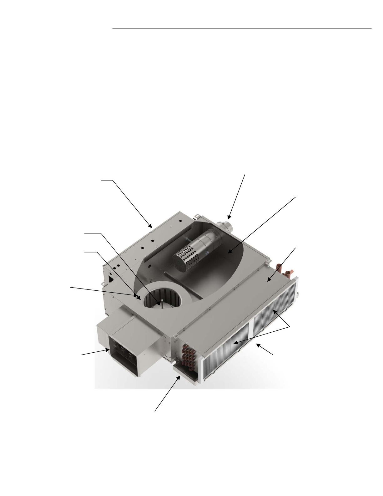
actuator. See Figure 1 for unit components.
FIGURE 1: LSC Unit Major Components (Unit Size 3 shown)
Primary Air Inlet c/w:
Aerocross – Airflow measuring device
Damper Blade
Control Enclosure
EcoShield Liner
ECM Motor
DWDI Centrifugal
Blower
Electric Heater
(Optional)
Sensible Cooling Coil
and
Hot Water Coil
Filter MERV8 (Optional)
Return Air:
Non Ducted (STD)
Ducted Flange (Optional)
Condensate Pan
6
Page 7
Pre - Installation
TU-LSC-IOM
WARNING
Hazardous Voltage!
Disconnect all electric power, including remote disconnects
and discharge all motor start/run capacitors before
servicing. Follow proper lockout/ tagout procedures to
ensure the power cannot be inadvertently energized. For
variable frequency drives or other energy storing
components provided by Titus or others, refer to the
appropriate manufacturer’s literature for allowable waiting
periods for discharge of capacitors. Verify with an
appropriate voltmeter that all capacitors have discharged.
Failure to disconnect power and discharge capacitors
before servicing could result in death or serious injury.
Receiving and Handling
Upon delivery, inspect all components for possible
shipping damage. See “Receiving Checklist” (below) for
detailed instructions. Titus recommends leaving units and
accessories in their shipping packages/skids for protection
and ease of handling until installation.
Shipping Package
The LSC units are multi packed and ship in pallets for
handling and storage ease. Each Unit has tagging
information such as the model number, sales order
number, serial number, unit size, piping connections, and
unit style to help properly locate the unit in the floor plan. If
specified, the unit will ship with tagging designated by the
customer.
Do not continue unpacking the shipment if it appears
damaged. Retain all internal packing, cartons, and crate.
Take photos of damaged material.
Notify the carrier’s terminal of the damage immediately
by phone and mail. Request an immediate joint inspection
of the damage by the carrier and consignee.
Notify your Titus representative of the damage and
arrange for repair. Have the carrier inspect the damage
before making any repairs to the unit.
Compare the electrical data on the unit nameplate with
the ordering and shipping information to verify the correct
unit is received.
Jobsite Storage
This unit is intended for indoor use only. Store the unit
indoors to protect the unit from damage due to the
elements. If indoor storage is not possible, make the
following provisions for outdoor storage:
1. Place the unit(s) on a dry surface or raised off the
ground to assure adequate air circulation beneath unit and
to assure that no portion of the unit contacts standing water
at any time.
2.Cover the entire unit with a canvas tarp only. Do not use
clear, black or plastic tarps as they may cause excessive
moisture condensation and equipment damage.
Receiving Checklist
Complete the following checklist immediately after
receiving unit shipment to detect possible shipping
damage.
Inspect individual pallets before accepting. Check for
rattles, bent corners, or other visible indications of
shipping damage.
If a unit appears damaged, inspect it immediately before
accepting the shipment. Manually rotate the fan wheel to
ensure it turns freely. Make specific notations concerning
the damage on the freight bill. Do not refuse delivery.
Inspect the unit for concealed damage before it is stored
and as soon as possible after delivery. Report concealed
damage to the freight line within the allotted time after
delivery. Check with the carrier for their allotted time to
submit a claim.
Do not move damaged material from the receiving
location. It is the receiver’s responsibility to provide
reasonable evidence that concealed damage did not occur
after delivery.
Installation Preparation
Before installing the unit, consider the following unit
location recommendations to ensure proper unit operation.
1. Clearances: Allow adequate service and code
clearances as recommended in “Service Access” (the next
section). Position the unit and skid assembly in its final
location.
2.Structural support: Ensure the structural support is strong
enough to adequately support the unit. The installer is
responsible for supply support rods for installation of ceiling
units.
3.Level: To ensure proper unit operation, install the unit
level (zero tolerance) in both horizontal axes. Failure to
level the unit properly can result in condensate
management problems, such as standing water inside the
unit.
4.Condensate line & piping: Consider coil piping and
condensate drain requirements. Verify condensate line is
continuously pitched 1 inch per 10 feet of condensate line
run to adequately drain condensate.
7
Page 8
TU-LSC-IOM
Pre – Installation (Cont.)
5. Wall & ceiling openings: concealed units require wall/
ceiling openings. Refer to submittal for specific dimensions
before attempting to install. Concealed units must meet the
requirements of the National Fire Protection Association
(NFPA) Standard 90A or 90B concerning the use of
concealed ceiling spaces as return air plenums. Refer to
the submittal for specific dimensions of ceiling openings.
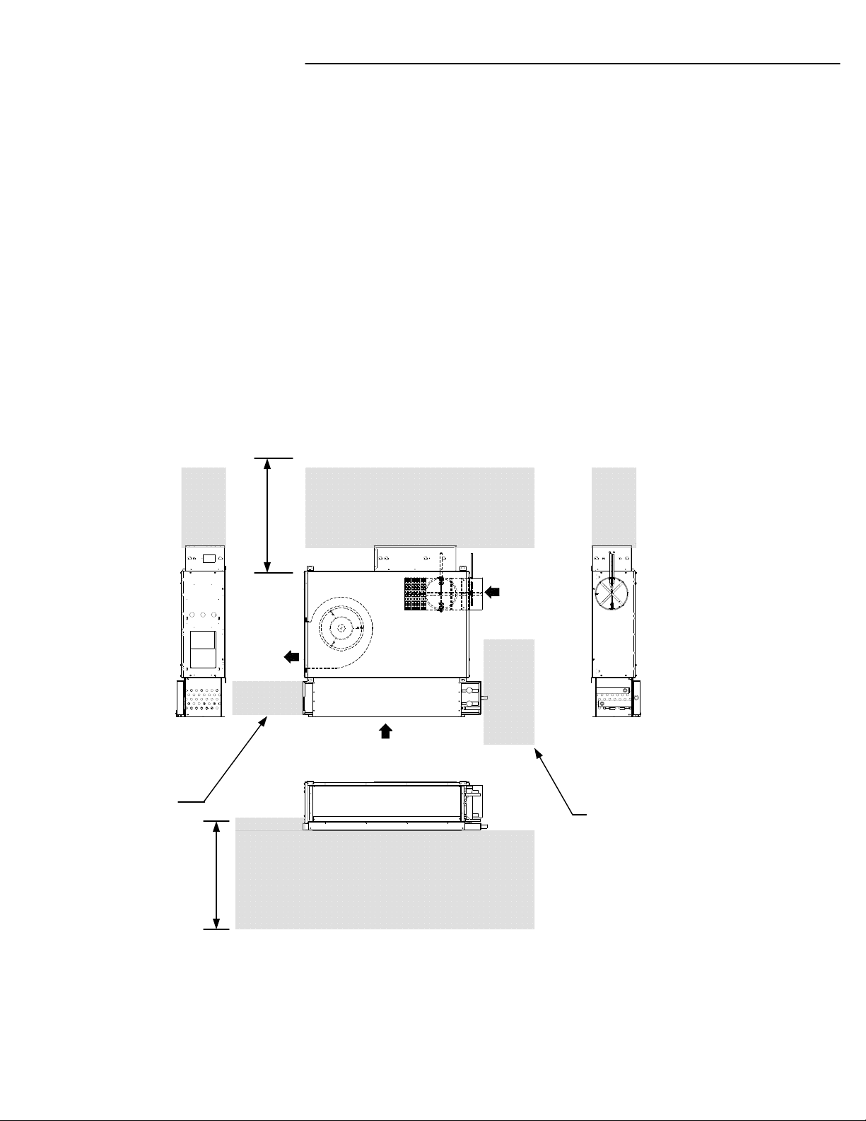
Service Access
Service access is available from the bottom and sides of
the units. Units have removable bottom and side panels to
allow access into the unit. See Figure 2 for recommended
service and operating clearances. Units have front or back
piping connections. Reference piping locations by facing
the front of the unit (airflow discharges from the front). The
control panel is always on the opposite the piping.
Figure 2.
Control Enclosure Access
Min 3'
Pre-Installation Checklist
Complete the following checklist before beginning unit
installation.
Verify the unit size and tagging with the unit nameplate.
Make certain the ceiling is solid, and sufficient to support
the unit and accessory weights. See “Dimensions and
Weights” section.
Allow minimum recommended clearances for routine
maintenance and service. Refer to unit submittals for
dimensions.
Allow 4' of straight duct before the first takeoff or before
the discharge ductwork makes any turns.
FRONT
Air
Discharge
Return Air
Alternative
Condensate Pan
Removal
Bottom Access Area for
Min 3'
Notes:
1. Right Hand unit shown. Control enclosure dictates the
handing of the unit.
2. Condensate Pan may be removed from the front or rear
of the unit.
3.All LSC units are installed with removable bottom access
panels.
Service & Maintenance
Air
Primary
REAR
Coil Connections Access +
Condensate Pan removal
8
Page 9

Components Data
Unit Size 03 04
Cooling Coil Data
TU-LSC-IOM
Heating Coil Data
Fan / Motor Data
Face Area (ft2)
L x D x H (in)
2 Row
4 Row
Volume (US Gal)
2 Row
4 Row
Fin per Inch
Face Area – ft2
1 Row
Volume – US Gal
1 Row
Fan Quantity
2.1875 2.1875
36 x 9 5/8 x 8 3/4 36 x 9 5/8 x 8 3/4
36 x 9 5/8 x 8 3/4 36 x 9 5/8 x 8 3/4
1.75 1.75
3.5 3.5
10 FPI 10 FPI
2.1875 2.1875
36 x 9 5/8 x 8 3/4 36 x 9 5/8 x 8 3/4
0.875 0.875
1 2
Size – Dia(in) x Width (in)
Motor Quantity
Motor Power (HP)
Filter Data
Quantity
Size L x H (Nominal in)
Type
Filtration Efficiency
Notes:
1. Filter dimensions are nominal dimensions
10 5/8 x 8 7/8 10 5/8 x 8 7/8
1 2
1 x 1/3 HP 2 x 1/3 HP
2 2
20 x 10 (each) 20 x 10 (each)
Pleated Pleated
MERV 8 MERV 8
9
Page 10
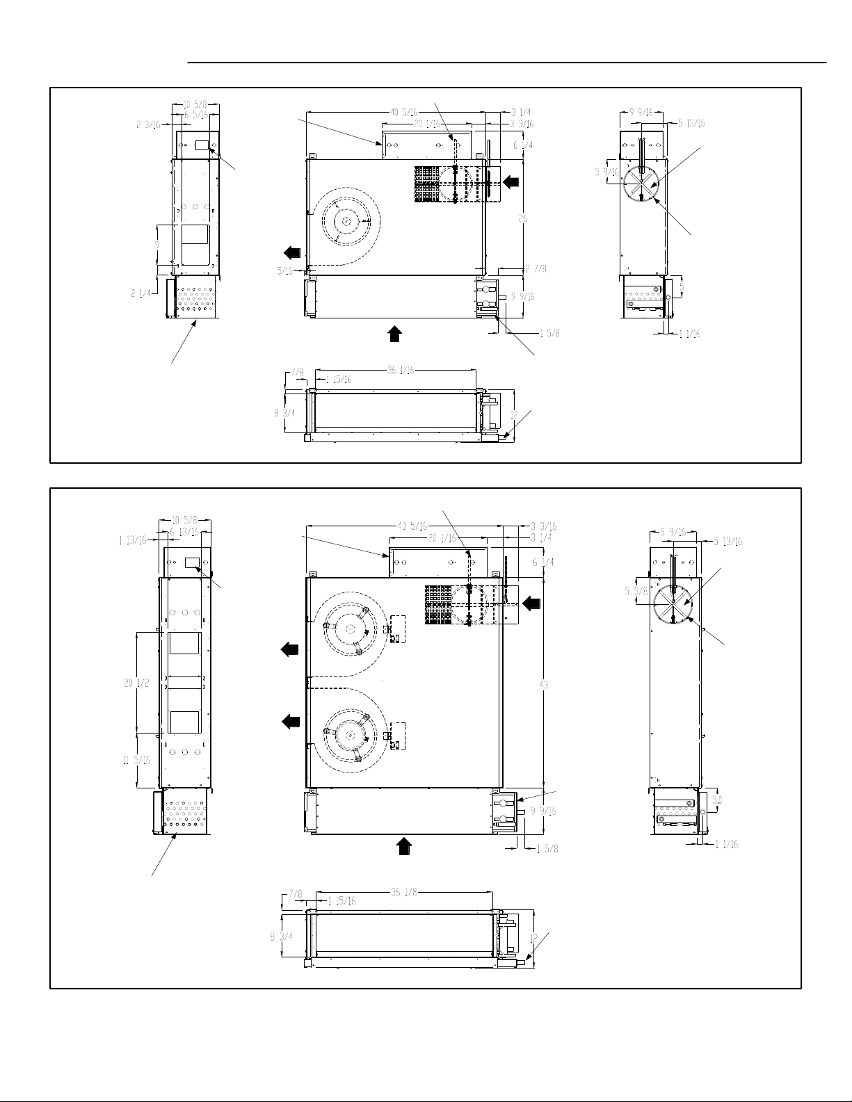
TU-LSC-IOM
Dimensions
Unit Size 3
Control Enclosure
ECM Motor
Controller
Supply Air
Water Coil
Unit Size 4 (With Round Primary Air Inlet)
Damper Shaft
Motor/Blower
Assy
Return
Induced Air
Damper Shaft
Primary Air
Supply
Condensate Pan
Condensate Pan Connection - ¾” Dia
Right Hand unit shown. All dimensions are in inches.
Primary Air
Damper
AeroCross
Velocity Sensor
Drawing No: LSC002
Drawing No: LSC001
Water Coil
Control Enclosure
ECM Motor
Controller
Supply Air
Motor/Blower
Assy(s)
Induced Air
Supply
Primary Air
Supply
Condensate Pan
Condensate Pan Connection - ¾” Dia
Primary Air
Damper
AeroCross
Velocity Sensor
10
Right Hand unit shown. All dimensions are in inches.
Page 11

Dimensions (Cont)
TU-LSC-IOM
Unit Size 4 (With Rectangular Primary Air Inlet)
Control Enclosure
ECM Motor
Controller
Supply Air
Water Coil
Damper Shaft
Motor/Blower
Assy(s)
Induced Air
Supply
Primary Air
Supply
Condensate Pan
Drawing No: LSC003
Primary Air
Damper
AeroCross
Velocity Sensor
Unit Size 3 – Electric Heater Option
Drawing No: LSC013
Condensate Pan Connection - ¾” Dia
Right Hand unit shown. All dimensions are in inches.
Unit Size 4 – Electric Heater Option
Drawing No LSC014
11
Page 12

TU-LSC-IOM
Return Air - Cooling/Heating Coils Flange Connection (No Filter)
Drawing No: LSC004
Coil Conections
Primary Air
Supply
Condensate
Right Hand unit shown. All
dimensions are in inches.
Pan
Weights
Return Air - Cooling/Heating Coils Flange Connection (No Filter)
Drawing No: LSC015
Right Hand unit shown. All
dimensions are in inches.
U)sbL( sthgieW gnippihs tinU nit Installed Weights (Lbs)
WEIGHTS (Lbs)
UNIT
SIZE
Basic Unit
3 110
4 160
Cooling + Heating Coils
2R 2+1R 4R 4+1R
14 17 25.5
22.5
14 17 22.5 25.5
Unit Labels
Each unit will have two main labels attached to the casing.
The FAN UNIT label lists:
Model Number
Model Number Description
Unit Power Supply requirements
Motor Horsepower
Full Load Amps
Electric Heater Power Supply requirements
Power – KW
Amperage consumption
Minimum Circuit Amps
Max Recommended Fuse
Heater
Electric
23
23
WEIGHTS (Lbs)
UNIT
SIZE
Basic Unit
3 110
4 160
Notes:
Includes the weight of water in the coils.
Unit Labels
Read all labels on a typical unit, before beginning
installation.
Cooling + Heating Coils
2R 2+1R 4R 4+1R
16.5 21 32.25
28
16.5 21 32.2528
NOTICE
LSC
Heater
Electric
23
23
The AIR FLOW label lists:
Model Number
Unit Size
Factory Order Number
TAG / Location - indicates the engineer's planned
location for the unit to be installed.
There may be other labels attached to the unit, as options or
codes may require.
If you have any questions, please contact the local TITUS
Representative for clarification. Have the key points from the
Flow label available for reference before calling.
Air
LSC
12
Page 13

Water Coil(s) Connections
TU-LSC-IOM
Units with Right Hand Control Panel
Check if provided.
Drawing No: LSC005
2R Cool 4R Cool
2R Cool
1R Heat
4R Cool
1R Heat
Units with Left Hand Control Panel
2R Cool
2R Cool
1R Heat
Drawing No: LSC006
4R Cool
4R Cool
1R Heat
13
Page 14

TU-LSC-IOM
Installation - Mechanical
Duct Connections
Install all air ducts according to National Fire Protection
Association standards for the Installation of Air
Conditioning and Ventilating Systems (NFPA 90A and
90B). Install all air ducts according to the National Fire
Protection Association standards for the “Installation of Air
Conditioning and Ventilation Systems other than
Residence Type (NFPA 90A) and Residence Type Warm
Air Heating and Air Conditioning Systems (NFPA 90B).
WARNING
Hazardous Voltage!
Disconnect all electric power, including remote disconnects
and discharge all motor start/run capacitors before
servicing. Follow proper lockout/ tagout procedures to
ensure the power cannot be inadvertently energized. For
variable frequency drives or other energy storing
components provided by Titus or others, refer to the
appropriate manufacturer’s literature for allowable waiting
periods for discharge of capacitors. Verify with an
appropriate voltmeter that all capacitors have discharged.
Failure to disconnect power and discharge capacitors
before servicing could result in death or serious injury.
Piping Considerations Hydronic Coil Piping
Before installing field piping to the coil, consider the
following:
• Coil connections can be 5/8-inch O.D. (or 1/2-inch
nominal) or 7/8-inch O.D. (or ¾-inch nominal) sweat
copper connections.
• The supply and return piping should not interfere with
the auxiliary drain pan or condensate line connection.
• Supply connection should always be at the bottom of
the coil and return at the top.
• An Air Vent valve must be installed at the highest point
of the water coil to allow removal of “air pockets” inside
the coil.
•The installer must provide adequate piping system
filtration and water treatment.
• Solder the joints using bridgit lead-free solder (ASTM
B32-89) to provide a watertight connection. Avoid
overheating factory soldered joints when soldering field
connections to the coil to prevent leakage from occurring.
The unit’s duct connections varies dependent on options
ordered. Titus recommends using galvanized sheet metal
ductwork with the LSC units. All duct connections should
be sealed and fasten with sheetmetal screws.
Note: Do not run screws through the removable front
panels.
Ductwork Recommendations
Follow the general recommendations listed below when
installing ductwork for the unit.
1. Discharge ductwork should run in a straight line,
unchanged in size or direction, for a minimum of 4'.
2.When making duct turns, placing takeoffs and
transitions avoid sharp turns and use proportional
splits, turning vanes, and air scoops when necessary.
3.When possible, construct, and orient supply ductwork
turns in the same direction as the fan rotation.
• Insulate all piping to coil connections as necessary after
connections and pressure test are complete.
Note: When installing a field piping package in a LSC
unit, allow sufficient room to remove the auxiliary drain
pan.
Condensate Drain Connection (If installed)
1. De-burr the pipe end before making the connection to
the drain pan.
2. Connect a 7/8-inch O.D. copper pipe or tube, with a
0.20 inch wall thickness, to the auxiliary drain pan. This
should be a mechanical connection that allows easy
removal of the auxiliary drain pan when servicing the
piping end pocket.
3 .Slide the copper pipe over the drain pan nipple and
tighten the collar on the pipe with a hose clamp (installer
supplied).
Maintain a continuous drain line pitch of one inch per ten
feet of drain line run to provide adequate condensate
drainage. Extend the drain line straight from the drain pan
a minimum distance of six inches before making any
turns. The installer must provide proper support for the
drain line to prevent undue stress on the auxiliary drain
pan.
Note: The installer is responsible for adequately
insulating field piping. See the “External Insulating
Requirements section for more information.
14
Page 15

Installation – Mechanical (Cont)
External Insulating Requirements
Insulate and vapor seal surfaces colder than surrounding
air dew-point to prevent unplanned condensation. Titus
recommends field-insulation of the following areas to
prevent potential condensate problems:
1. Supply and return water piping connections
2. Condensate drain lines and connections
3. Fresh air intake duct connections
4. Discharge duct connections
TU-LSC-IOM
15
Page 16

TU-LSC-IOM
Installation – General
Installing the Unit
Follow the procedures below to install the unit properly.
Refer to “Dimensions and Weights,” Section for specific
unit dimensions and mounting hole locations.
panel against the unit,
NOTICE
Electrical Wiring!
Do not allow electrical wire to fall between the unit and
installation surface. Failure to comply may result in
electrical shorts or difficulty accessing wires.
NOTICE
Motor Overload!
All unit panels and filters must be in place prior to unit
startup. Failure to have panels and filters in place may cause
motor overload.
Install horizontal units suspended from the ceiling using metal
straps or the optional Hanging Brackets located on the top of the
unit. The hanger holes allow a maximum shank size of 1/2-inch
diameter threaded rods or lag screws (installer provided).
Note: Follow the requirements of National Fire Protection
Association (NFPA) Standard 90A or 90B, concerning the use of
concealed ceiling spaces as return air plenums.
Hanger Brackets – Size 3 Unit
Drawing No: LSC009
Top View
Side View
Drawing No: LSC010
Hanger Brackets – Size 4 Unit
Top View
Follow the installation procedure below.
1. Prepare the ceiling opening for recessed units. Reference
the unit submittals for dimensions.
2. Position and install the suspension rods or a suspension
device (supplied by installer) according to the unit model and
size in “Dimensions and Weights,”
4. Level the unit by referencing the chassis end panels.
Adjust the suspension device.
5. Complete piping and wiring connections, in addition to any
necessary ductwork as instructed in the following sections.
6. Install the bottom panel before starting the unit.
7. If installed ensure condensate drain line is pitched one inch
per ten feet of pipe away from the LSC unit.
Side View
16
Page 17

Installation Checklist
TU-LSC-IOM
WARNING
Hazardous Voltage w/Capacitors!
Disconnect all electric power, including remote
disconnects and discharge all motor start/run
capacitors before servicing. Follow proper lockout/
tagout procedures to ensure the power cannot be
inadvertently energized. For variable frequency drives
or other energy storing components provided by Trane
or others, refer to the appropriate manufacturer’s
literature for allowable waiting periods for discharge of
capacitors. Verify with an appropriate voltmeter that all
capacitors have discharged. Failure to disconnect
power and discharge capacitors before servicing
could result in death or serious injury
NOTICE
Unit Leveling!
The unit must be installed level (zero tolerance) in both
horizontal axis for proper operation.
The following checklist is only an abbreviated guide to the
detailed installation procedures given in this manual. Use this
list to ensure all necessary procedures are complete. For more
detailed information, refer to the appropriate sections in this
manual.
10. Complete all necessary duct connections.
11. Install the filed supplied controls.
12. Complete all interconnection wiring.
13. Connect electrical supply power according to the
NEC and unit wiring diagrams.
14. Remove any miscellaneous debris, such as
sheetrock dust, that may have infiltrated the unit during
construction.
15. Replace the air filter (if installed) as required.
1. Inspect the unit for shipping damage.
2. Level installation location to support the unit weight
adequately. Make all necessary ceiling openings to allow
adequate air flow and service clearances.
3. Ensure the unit chassis is installed level.
4. Verify that wall and ceiling openings are properly cut per
the unit submittals.
5. Verify that installation of units meets the national Fire
Protection Association (N.F.P.A.) Standard 90A or 90B
concerning the use of concealed ceiling spaces as return air
plenums. Verify correct ceiling opening dimensions on unit
submittals. Secure the unit and any accessory items properly
to the ceiling support rods.
6. Complete all piping connections correctly.
7. Check field sweat connections for leaks and tighten the
valve stem packing, and piping package unions if necessary.
8. Install condensate drain line connections if required.
9. Pitch condensate drain line away from LSC unit one-inch
drop per ten feet of pipe.
17
Page 18

TU-LSC-IOM
Installation - Electrical
Unit Wiring Diagrams
Specific unit wiring diagrams, based on unit options
ordered, are provided inside each unit and can be easily
removed for reference. Use these diagrams for
connections or trouble analysis. Wiring diagrams are
attached on the inside of the Control enclosure
Supply Power Wiring
Refer to the unit nameplate to obtain the minimum circuit
ampacity (MCA) and maximum fuse size (MFS) or
maximum circuit breaker (MCB) to properly size field
supply wiring and fuses or circuit breakers.
Refer to the unit operating voltage listed on the unit wiring
schematic, submittal, or nameplate. Reference the wiring
schematic for specific wiring connections.
Note: All field wiring should conform to NEC and all
applicable state and local code requirements. The control
enclosure is always on the end opposite the piping
connections. Access the control box by removing the two
screws that secure the front cover. This will allow the panel
to be removed, to provide access to the electrical
components.
Recommendation: Do not bundle or run interconnection
wiring in parallel with or in the same conduit with any highvoltage wires (110 V or greater). Exposure of
interconnection wiring to high voltage wiring, inductive
loads, or RF transmitters may cause radio frequency
interference (RFI). In addition, improper separation may
cause electrical noise problems. Therefore, use shielded
wire (Belden 83559/83562 or equivalent) in applications
that require a high degree of noise immunity. Connect the
shield to the chassis ground and tape at the other end.
Note: Do not connect any sensor or input circuit to an
external ground connection.
Table 4. Electrically commutated motors Full Load
Amps
Unit
Size
Motor hp277/1/60
3
4
1
/
3
2 x 1/3
FLA
2.3
4.6
208/1/60
FLA
2.7
5.1
120/1/60
FLA
4.1
8.6
All fan motors are single phase, same voltage as electric
coil (when supplied), with exception that 277 V motors are
used with 480V, 3 phase coils (4 wire wye).
NOTICE
Use Copper Conductors Only!
Unit terminals are not designed to accept other types of
conductors. Failure to use copper conductors may result in
equipment damage.
If the unit does not have a disconnect switch, the power
leads and ground terminal are situated inside the high
voltage compartment in the control enclosure. If the unit
has a disconnect switch, power connections are done
directly to the disconnect switch located in the control
enclosure.
NOTICE
Equipment Damage!
Unit transformer provides power to the LSC unit only. Field
connections directly to the transformer may create
immediate or premature unit component failure.
FLA = Full Load Amperage, as tested in accordance with
UL 1995
Minimum Circuit Ampacity (MCA) and Maximum Fuse
Size (MFS) Calculations for Fan-Coils with Single
Phase Electric Heat
Heater amps = (heater kW x 1000)/heater voltage
MCA = 1.25 x (heater amps + all motor FLAs)
MFS type circuit breaker = (2.25 x largest motor FLA) +
second motor FLA + heater amps (if applicable)
Select a standard fuse size or circuit breaker equal to the
MCA. Use the next larger standard size if the MCA does
not equal a standard size.
Standard fuse sizes are: 15, 20, 25, 30, 35, 40, 45, 50, 60
amps.
LSC Unit electric heat MBh = (heater kW)*(3.413)
18
Page 19

Installation – Electrical (Cont)
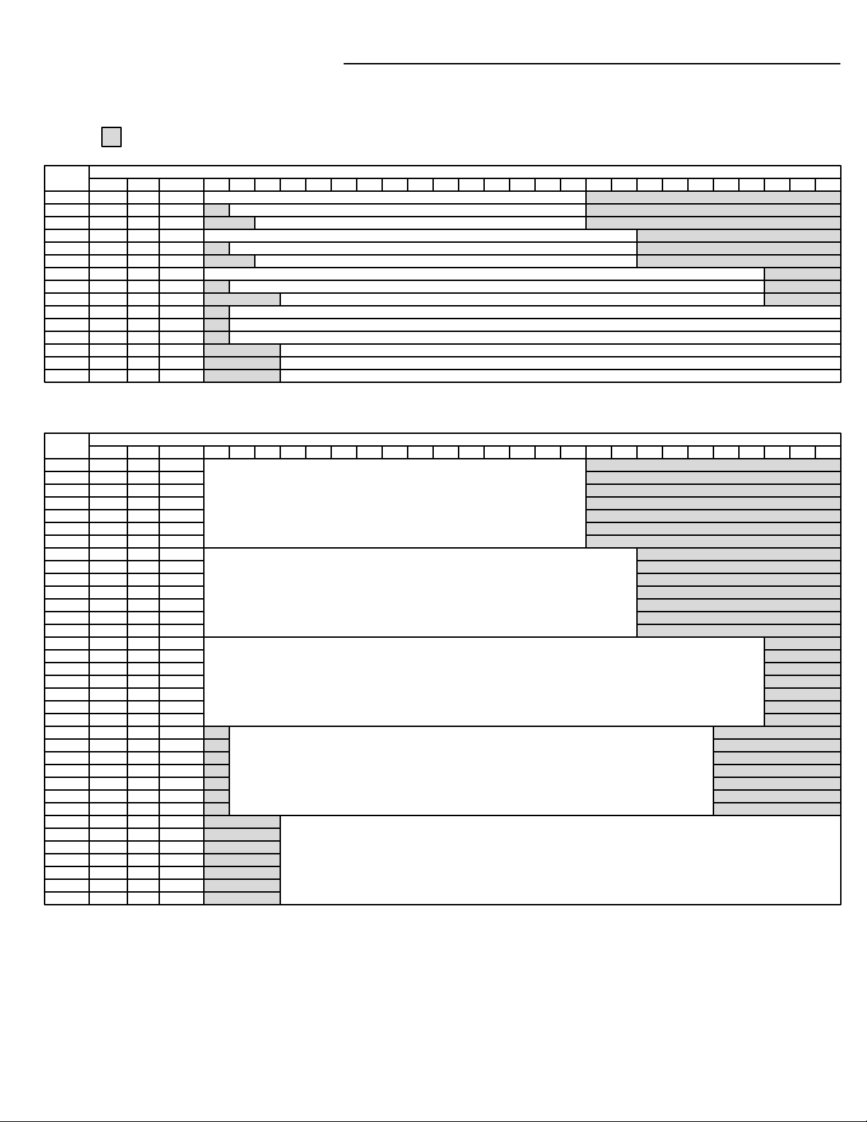
Electric Heater MIN - MAX KW – LSC Size 3
= Electric Heater NOT available
TU-LSC-IOM
Code
E21
E22
E23
E31
E32
E33
E41
E42
E43
E61
E62
E63
E91
E92
E93
Code
L21
L22
L23
L24
L25
L26
L27
L31
L32
L33
L34
L35
L36
L37
L41
L42
L43
L44
L45
L46
L47
L61
L62
L63
L64
L65
L66
L67
L91
L92
L93
L94
L95
L96
L97
208V
208V
208V
240V
240V
240V
277V
277V
277V
208V
208V
208V
480V
480V
480V
208V
208V
208V
208V
208V
208V
208V
240V
240V
240V
240V
240V
240V
240V
277V
277V
277V
277V
277V
277V
277V
208V
208V
208V
208V
208V
208V
208V
480V
480V
480V
480V
480V
480V
480V
1PH
1PH
1PH
1PH
1PH
1PH
1PH
1PH
1PH
3PH
3PH
3PH
3PH
3PH
3PH
1PH
1PH
1PH
1PH
1PH
1PH
1PH
1PH
1PH
1PH
1PH
1PH
1PH
1PH
1PH
1PH
1PH
1PH
1PH
1PH
1PH
3PH
3PH
3PH
3PH
3PH
3PH
3PH
3PH
3PH
3PH
3PH
3PH
3PH
3PH
1 Step
2 Step
3 Step
1 Step
2 Step
3 Step
1 Step
2 Step
3 Step
1 Step
2 Step
3 Step
1 Step
2 Step
3 Step
PWM
2 STG
0-10V
0-20mA
2-10V
4-20mA
Incremental
T-Stat
Binary
3 Point
Floating
PWM
2 STG
0-10V
0-20mA
2-10V
4-20mA
Incremental
T-Stat
Binary
3 Point
Floating
PWM
2 STG
0-10V
0-20mA
2-10V
4-20mA
Incremental
T-Stat
Binary
3 Point
Floating
PWM
2 STG
0-10V
0-20mA
2-10V
4-20mA
Incremental
T-Stat
Binary
3 Point
Floating
PWM
2 STG
0-10V
0-20mA
2-10V
4-20mA
Incremental
T-Stat
Binary
3 Point
Floating
1.0 1.5 2.0 2.5 3.0 3.5 4.0 4.5 5.0 5.5 6.0 6.5 7.0 7.5 8.0 8.5 9.0Voltage PH Type
STAGED - Electric Heater MIN – MAX KW
LYNERGY - Electric Heater MIN – MAX KW
1.0 1.5 2.0 2.5 3.0 3.5 4.0 4.5 5.0 5.5 6.0 6.5 7.0 7.5 8.0 8.5 9.0Voltage PH Type
NOTES:
1 - All KW’s must remain within Minimum and Maximum range shown for each unit size and step.
2 – Electric Coils are attached to the unit discharge and wired to a control panel for “ Single Point” electric connections.
3 – Electric Coils only include:
Automatic reset thermal cutout (one per step)
Positive Pressure airflow switch
Magnetic Contactor per step for Analog and Digital controls and PE switch for each step for pneumatic units.
19
Page 20
TU-LSC-IOM
Installation – Electrical (Cont)
Electric Heater MIN - MAX KW – LSC Size 4
= Electric Heater NOT available
Code
L21
L22
L23
L31
L32
L33
L41
L42
L43
L61
L62
L63
L91
L92
L93
Code
L21
L22
L23
L24
L25
L26
L27
L31
L32
L33
L34
L35
L36
L37
L41
L42
L43
L44
L45
L46
L47
L61
L62
L63
L64
L65
L66
L67
L91
L92
L93
L94
L95
L96
L97
208V
208V
208V
240V
240V
240V
277V
277V
277V
208V
208V
208V
480V
480V
480V
208V
208V
208V
208V
208V
208V
208V
240V
240V
240V
240V
240V
240V
240V
277V
277V
277V
277V
277V
277V
277V
208V
208V
208V
208V
208V
208V
208V
480V
480V
480V
480V
480V
480V
480V
1PH
1PH
1PH
1PH
1PH
1PH
1PH
1PH
1PH
3PH
3PH
3PH
3PH
3PH
3PH
1PH
1PH
1PH
1PH
1PH
1PH
1PH
1PH
1PH
1PH
1PH
1PH
1PH
1PH
1PH
1PH
1PH
1PH
1PH
1PH
1PH
3PH
3PH
3PH
3PH
3PH
3PH
3PH
3PH
3PH
3PH
3PH
3PH
3PH
3PH
PWM
2 STG
0-10V
0-20mA
PWM
2 STG
0-10V
0-20mA
PWM
2 STG
0-10V
0-20mA
PWM
2 STG
0-10V
0-20mA
PWM
2 STG
0-10V
0-20mA
PWM
2 STG
0-10V
0-20mA
2-10V
4-20mA
Incremental
T-Stat
Binary
3 Point
Floating
PWM
2 STG
0-10V
0-20mA
2-10V
4-20mA
Incremental
T-Stat
Binary
3 Point
Floating
PWM
2 STG
0-10V
0-20mA
2-10V
4-20mA
Incremental
T-Stat
Binary
3 Point
Floating
PWM
2 STG
0-10V
0-20mA
2-10V
4-20mA
Incremental
T-Stat
Binary
3 Point
Floating
PWM
2 STG
0-10V
0-20mA
2-10V
4-20mA
Incremental
T-Stat
Binary
3 Point
Floating
1.0 1.5 2.0 2.5 3.0 3.5 4.0 4.5 5.0 5.5 6.0 6.5 7.0 7.5 8.0 8.5 9.0 9.5 10.0 10.5 11.0 11.5 12.0 13.0 14.0Voltage PH Type
STAGED - Electric Heater MIN – MAX KW
LYNERGY - Electric Heater MIN – MAX KW
1.0 1.5 2.0 2.5 3.0 3.5 4.0 4.5 5.0 5.5 6.0 6.5 7.0 7.5 8.0 8.5 9.0 9.5 10.0 10.5 11.0 11.5 12.0 13.0 14.0Voltage PH Type
`
NOTES:
1 - All KW’s must remain within Minimum and Maximum range shown for each unit size and step.
2 – Electric Coils are attached to the unit discharge and wired to a control panel for “ Single Point” electric connections.
3 – Electric Coils only include:
Automatic reset thermal cutout (one per step)
Positive Pressure airflow switch
Magnetic Contactor per step for Analog and Digital controls and PE switch for each step for pneumatic units.
20
Page 21

ECM Overview and Setup
TU-LSC-IOM
Overview
This section addresses the Titus ECM motor which is
standard on all LSC units. The ECM motor provides
outstanding comfort, safety, and performance with greatly
reduced energy consumption compared to traditional units
with permanent split capacitance AC motors and with
proper installation and operation the units will provide a
long service life . The ECM motor provides a high degree
of flexibility and configurability, with the simplicity of
customized factory configurations appropriate to most
installations. Very little intervention is needed by service
and installation personnel in most applications; however,
installers must read through this entire section before
beginning installation of the new equipment. This literature
focuses on unit motors and associated controls.
General Information
There are four primary components that enable the ECM
technology on the LSC units:
1. Titus ECM Motor
2. ECM Engine Board
3. PWM Controllers
4. Inductors
The motors and modules are combined as a system, and
cannot work without each other.
ECM Engine Board
3. The LSC unit is equipped with either a manual control or
a remote control PWM fan speed controller, mounted on
the side of the line voltage control enclosure.
A - Remote Signal PWM Controller
ECM motors shipped with remote PWM controller require a
signal from the DDC controller to control fan speed.
B- Manual/Unit PWM Controller
ECM Motor
ECM Motor Fan Flow Adjustment
NOTICE
Before starting the fan motor, follow steps 1 and 2
1. Discharge ductwork should be connected. The
minimum
recommended discharge static pressure is 0.2" wg. Be
sure that any fan packing is removed from units prior!
ECM motors with manual PWM controllers are shipped
from the factory at design CFM when provided. Otherwise
motors are shipped at motor full speed setting.
4. Allow motor to run-in at least 15 minutes before
adjusting speed. During initial run-in, check ductwork
connections for leaks and repair if necessary. (Do not
adjust fan speed down if ductwork is not connected).
5. Set the unit to full heating (maximum induction). Adjust
and set remote balancing dampers, if present. Adjust the
speed control to deliver the required CFM by measuring air
quantity at the room outlets.
6. Proceed to primary air adjustment procedure, detailed in
control installation information. Fan should be re-adjusted
with primary air and ventilation air at maximum setpoint,
to insure that no supply air is discharged at the induction
port.
2. All foreign materials should be removed from duct
system. Filters should be installed where required.
21
Page 22

TU-LSC-IOM
ECM Overview and Setup
Manual / Unit PWM Signal Interface Board
Signal
RPM/CFM
Adjustment
RPM/CFM Indicator
24VAC
Power Supply
Communication
connector to
ECM Motor
The Manual PWM interface board allows accurate manual
adjustment and monitor of fan with the GE Electric ECM
Motor.
The Manual interface board features a 4 digit LED
numerical display to allow easy reading in dark spaces.
Watch the display and set the flow index with a screwdriver
adjust. Twenty seconds later, the display shows the
motor RPM. Then, the display periodically alternates
between the flow index and motor RPM.
Operation
GE ECM™ motors configured for Vspd operation are
factory configured for external torque or airflow
adjustment. A numerical flow index accurately adjusts the
fan to the desired torque or airflow. The flow index is a
number from 0-100 having a linear relationship to the
minimum to maximum torque or airflow range specified by
Titus. Refer to the fan specifications, data and charts to
convert the flow index to torque or mass airflow.
The Manual PWM interface board allows local on/off and
fan airflow adjustment. Rotating a single screwdriver
adjuster changes the variable output signal to the motor
from off to full output. While rotating the adjuster, a
numerical flow index is locked on the illuminated
numerical display. After adjustment, the display
shows fan RPM.
Remote PWM Signal Interface Board Details
Jumper Link
Control Signal Type
Manual Adjust
Signal
Communication
connector to
ECM Motor
Control Signall
RPM Out
24VAC Aux Power
24VAC Power Supply
The remote interface allows industry standard 0-10Vdc
automation signals to adjust and monitor General Electric’s
ECM Motor.
The interface board provides remote adjustment of the
ECM output from 0% to 100% of the programmed control
range. A signal lamp on the control continuously flashes
out the flow index
the flow index. A 0-10Vdc signal connects RPM to the
automation control. Jumpers allow the Interface to be
configured for 0-10Vdc automation signal, 2-10Vdc
automation signal, and manual/override control. The
interface can also be used for stand-alone manual control.
The green lamp continuously indicates the flow index. After
a pause, the lamp flashes out the tens digit, then the units
digit of a number between 1 and 99. Long flashes
represent the tens digit, and short flashes represent the
units digit. For example, a flow index of 23 flashes two
longs, then three shorts.
Two extra long flashes indicate a flow index of 0. An extra
long flash and ten short flashes indicates a flow index of
100. The lamp flashes the signal that was present when
the flash sequence started.
Turning Adjust controls the ECM motor to the manually
adjusted setting. The manual setting has authority for 15
minutes.Set the unit to full heating (maximum induction).
Adjust and set remote balancing dampers, if present.
Adjust the speed control to deliver the required CFM by
measuring air quantity at the room outlets.
2. Instruments are not required to read
22
Page 23

ECM Overview and Setup
TU-LSC-IOM
Remote PWM Signal Interface Board Details
Jumpers
P - Jumper provides ON/OFF control by
switching the motor's "GO" control line
when the input signal drops below the
2 volt (4 mA) operating point. without the
jumper, turn power to the interface board
+ On/Off to control motor On/Off.
Rotating Adjust changes the Flow Index
from 0 to 100.
The “P” jumper also allows manual on/off control.
Signal with
“P” Jumper Out
Input / Output Control Signals
"Opt" Configuration - 0-10 Vdc = 1% to 100%
"P" Configuration - 2-10Vdc = 0-100%
- 4-20mA = 0-100%
- ON/OFF Control Between1 & 2
Vdc (2 & 4 mA)
RPM Signal - 0-10 Vdc, 5 mA max. = 0 to 2,000
RPM in 10 RPM steps
Outputs Go & VSpd - 22Vdc @ 5mA
DDC Control - Air Balance
If the DDC Controller signal is already installed, air
balance can be achieved using the DDC Controller
software tools. Please notice that a control signal less than
0.2Vdc may put the interface board into manual override.
Avoid setting the DDC signal to less than 0.2Vdc.
WARNING
Turning Adjust potentiometer locks out the BAS
signal for 15 minutes
Signal with
“P” Jumper In
M - Jumper enables manual override. Manual override is
overridden when the 0-10V automation signal exceeds
0.2Vdc.
Manual override controls the motor before Building
Automation System (BAS) is installed, or when BAS fails.
Without the “M” jumper, manual override is enabled
whenever Adjust is turned. It is disabled by causing the
Interface board to turn the motor off/on 5 times while signal
is greater than 0.1Vdc.
R - Jumper reverses Adjust rotation so adjustment is
correct from the component side of the board.
Opt - The Opt. space has no function. The space
may be used to store an unused jumper.
Cycle power ON/OFF for faster lockout removal.
Manual Air Balance
The interface board can be manually adjusted before the
DDC Controller signal is available. The balancer’s manual
adjustment has authority until automation is connected.
Air Balancer
1. Use Adjust to set the air flow. This adjustment will have
authority for at least 15 minutes.
2. Read the flashing green light and record the flow index
on the air balance report.
DDC Integrator
1. Set the Signal to 0Vdc to invoke manual override.
2. Record the RPM on the air balance report.
3. Enter the flow index the air balancer entered on the air
balance report.
4. Observe the RPM is at or near the RPM observed in
step 2.
5. Cycle the motor on/off 5 times. This clears the manual
override function unless the “M” jumper is in
place.
23
Page 24

TU-LSC-IOM
Pre Start-Up
Pre-Startup Checklist
Complete this checklist after installing the unit to verify all
recommended installation procedures are complete before
unit startup. This does not replace the detailed instructions
in the appropriate sections of this manual. Disconnect
electrical power before performing this checklist. Always
read the entire section carefully to become familiar with the
procedures.
WARNING
Hazardous Voltage w/Capacitors! Disconnect all
electric power, including remote disconnects and discharge
all motor start/run capacitors before servicing. Follow proper
lockout/ tagout procedures to ensure the power cannot be
inadvertently energized. For variable frequency drives or
other energy storing compo nents provided by Trane or
others, refer to the appropriate manufacturer’s literature for
allowable waiting periods for discharge of capacitors. Verify
with an appropriate voltmeter that all capacitors have
discharged. Failure to disconnect power and discharge
capacitors before servicing could result in death or serious
injury.
Receiving
Inspect unit and components for shipping damage. File
damage claims immediately with the delivering carrier.
Check unit for missing material. Look for ship-with
options and sensors that may be packaged separately
from the main unit.
Unit Piping
1. Properly vent the hydronic coil to allow water flow
through the unit.
2. Tighten all pipe connections adequately.
3. Set water flow to the unit properly if unit piping has the
circuit setter valve (installed by others).
4. Check strainers (if installed by others) for debris after
apply system water.
5. Verify the condensate drain piping is complete for the
unit drain pan.
7. Ensure the drain pan and condensate line are not
obstructed. Remove any foreign matter that may have
fallen into the drain pan during installation.
Electrical
Check all electrical connections for tightness.
Electrical Note: Some circumstances may require the unit
to run before building construction is complete. These
operating conditions may be beyond the design
parameters of the unit and may adversely affect the unit.
Check nameplate unit data so that it matches the sales
order requirements.
Unit Location
1. Ensure the unit location is adequate for unit dimensions,
ductwork, piping, and electrical connections.
2. Ensure access and maintenance clearances around the
unit are adequate.
Unit Mounting
1. Ensure unit is installed level.
Component Overview
1. Ensure the fan rotates freely in the correct direction.
2.Ensure all unit access panels are in place.
3.Verify that a clean air filter is in place.
24
Page 25

Maintenance
Maintenance Procedures
Perform the following maintenance procedures to
ensure proper unit operation.
WARNING
Live Electrical Components! During installation,
testing, servicing and troubleshooting of this product, it may
be necessary to work with live electrical components. Have a
qualified licensed electrician or other individual who has
been properly trained in handling live electrical components
perform these tasks. Failure to follow all electrical safety
precautions when exposed to live electrical components
could result in death or serious injury.
WARNING
Disconnect all electric power, including remote
disconnects and discharge all motor start/run
capacitors before servicing. Follow proper lockout/
tagout procedures to ensure the power cannot be
inadvertently energized. For variable frequency drives
or other energy storing components provided by Trane
or others, refer to the appropriate manufacturer’s
literature for allowable waiting periods for discharge of
capacitors. Verify with an appropriate voltmeter that all
capacitors have discharged. Failure to disconnect
power and discharge capacitors before servicing
could result in death or serious injury.
Air Filters
TU-LSC-IOM
Inspecting and Cleaning Drain Pans
Clean the unit drain pan to ensure that any potential
condensate drains. Check the condensate drain pan and
drain line to assure the condensate drains properly at least
every six months or as dictated by operating experience. If
evidence of standing water or condensate overflow exists,
immediately identify and remedy the cause. Clean the
drain pans of any moisture or debris.
Coil Maintenance
Keep coils clean to maintain maximum performance. For
operation at its highest efficiency, clean the coil often
during periods of high demand or when dirty conditions
prevail. Clean the coil a minimum of once a year to prevent
dirt buildup in the coil fins, where it may not be visible.
Remove large debris from the coils and straighten fins
before cleaning. Remove filters before cleaning. Clean the
coil fins using steam with detergent, hot water spray and
detergent, or a commercially available chemical coil
cleaner. Be sure to rinse coils thoroughly after cleaning.
WARNING
Hazardous Chemicals! Coil cleaning agents can be
either acidic or highly alkaline. Handle chemical carefully.
Proper handling should include goggles or face shield,
chemical resistant gloves, boots, apron or suit as required.
For personal safety refer to the cleaning agent
manufacturer’s Materials Safety Data Sheet and follow all
recommended safe handling practices. Failure to follow all
safety instructions could result in death or serious injury.
Change or clean air filters at least twice a year. Filters
require more frequent care under high load or dirty air
conditions since a clogged filter reduces airflow. Pleated
media filters are available for all units.
Depending on the Filter Removal Option installed in the
unit, filters can be removed from the unit in two ways:
1 - Side removal – from the either side of the coil
2 - Bottom removal – from the bottom of the coil side
NOTICE
Replace All Panels and Filters Properly! All unit
panels and filters must be in place prior to unit startup.
Failure to have panels and filters in place could result in
equipment damage.
Inspecting and Cleaning Coils
Coils become externally fouled as a result of normal
operation. Dirt on the coil surface reduces it’s ability to
transfer heat that can result in comfort problems, increased
airflow resistance and thus increased operating energy
costs. If the coil surface dirt becomes wet, which
commonly occurs with cooling coils, microbial growth
(mold) may result, causing unpleasant odors and serious
health-related indoor air quality problems. Inspect coils at
least every six months or more frequently as dictated by
operating experience. Cleaning frequently is dependent
upon system operating hours, filter maintenance, and
efficiency and dirt load. Follow the suggested methods in
the following paragraphs.
25
Page 26

TU-LSC-IOM
Maintenance (Cont)
Hydronic Coil Cleaning Procedure
1. Disconnect all electrical power to the unit.
2. Don the appropriate personal protective equipment
(PPE).
3. Access both sides of the coil.
4. Use a soft brush to remove loose debris from both sides
of the coil.
5. Use a steam cleaning machine, starting from the top of
the coil and working downward. Clean the leaving air side
of the coil first, then the entering air side. Use a block-off to
prevent steam from blowing through the coil and into a dry
section of the unit.
6. Repeat step five as necessary. Confirm that the drain
line is open following completion of the cleaning process.
7. Allow the unit to dry thoroughly before putting the system
back into service.
8. Straighten any coil fins that may be damaged with a fin
rake.
9. Replace all panels and parts and restore electrical power
to the unit.
Winterizing the Coil
Make provisions to drain coils that are not in use, especially
when subjected to freezing temperatures. To drain the coil,
blow the coil out with compressed air. Next, fill and drain
the tubes with full-strength ethylene glycol several times.
Drain the coil as completely as possible.
Work Instruction Steps
In general, replacement of a motor needs to be carried out
as follows:
1. Remove front panels of unit.
2.Free the motor and crossover harnesses from the fan
board, by unplugging the two electric multi plugs from the
motor.
Depress Locking
tabs
3.Remove the fan housing with the motor and loosen fan
Allen screw on the shaft.
4.Unscrew the motor from the fan housing and remove.
5.Insert the replacement motor.
Periodic Maintenance Checklists
NOTICE
Coil Freeze-up Damage!
Failure to properly drain and vent coils when not in
use during freezing temperatures may result in coil
freeze-up damage.
Replacing Motors
Motors are attached to the fan Blower with screws at the
rear of the motors. Fan wheels are attached with Allen
screws on the fan hubs. In most applications, it is
necessary to remove the fan blower to change out the
motor. The fan blower is easily removable, with screws on
the top and bottom edges of fan blower.
NOTICE
Heavy Object!
Support the Fan Blower when removing it from the unit.
Failure to properly support Fan Blowerd may result in minor
to moderate personal injury.
The following check list provides the recommended
maintenance schedule to keep the unit running efficiently.
Monthly Maintenance
1. Inspect unit air filters. Clean or replace if airflow is blocked
or if filters are dirty.
2.Check the drain pans s to be sure the pans are clean and
do not impede the potential condensate flow through the drain
line.
Annual Maintenance
Check and tighten all set screws, bolts, locking collars and
sheaves.
1. Inspect the unit liner clean or repair to provide unit
protection.
2.Inspect the fan wheel and housing for damage. Rotate the
fan wheel manually to be sure movement is not blocked by
obstructions.
3.Inspect the coil fins for excessive dirt or damage. Remove
dirt and straighten fins.
4.Clean and tighten all electrical connections.
5.Inspect the primary air damper and ensure that it rotates
freely from o to 100% open.
26
Page 27

 Loading...