

Page 1

INSTALLATION &
OPERATION MANUAL
Helios
SOLAR VAV DIFFUSER
Redefine your comfort zone. ™ | www.titus-hvac.com
Page 2
IOM
HELIOS
Helios IOM
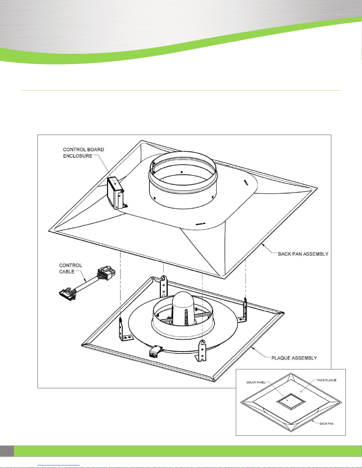
UNPACKING
The units are shipped in two major sub-assemblies; the back pan assembly
and the plaque assembly. An interface cable and quick start instructions
are included and shipped loose.
Locate the control cable in the box (shown below). This cable used to
connect the control board to the plaque assembly. Remove the top
cardboard insert. Remove the diffuser back pan and plaque from the
packaging taking care.
Precautions:
Care should be taken where handling the plaque assembly. The solar
panel can be damaged or dislodged by applying pressure to it or dropping
the plaque on a hard surface.
2
IOM - HELIOS
Redefine your comfort zone. ™ | www.titus-hvac.com
Page 3
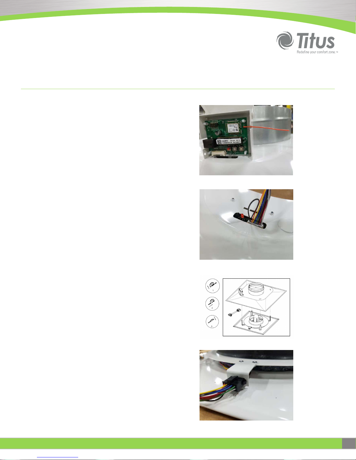
Standalone Installation
1. On the back pan, locate the control box and flip the cover open. There is
an orange antenna on the control board. Rotate the antenna wire into the
notch in the control box housing. Straighten it so it sticks straight out from
the control box. Close the cover.
2. Plug the white connector of the interface cable into the control board
which is accessible through the slot in the back pan.
Figure 2. Antenna position
3. Install the back pan into the ceiling grid and connect the duct work to
back pan inlet.
4. Install the plaque assembly:
• 1. Install the plaque assembly into the back pan by inserting
the hanger legs into the mating slots in the back pan.
• 2. Rotate the plaque slightly clock-wise to align
the hook tip with the small slot.
• 3. Lower the plaque to seat the hook tip in the small slot.
Warning: Do not apply pressure to solar panel.
5. Plug the black connector of the interface cable into receptacle on the
plaque assembly which is located close to the edge of the plaque.
Figure 3. Control board wiring connection
Figure 4. Plaque installation
Figure 5.Plaque assembly wiring connection
Redefine your comfort zone. ™ | www.titus-hvac.com
IOM - HELIOS
3
Page 4
IOM
HELIOS
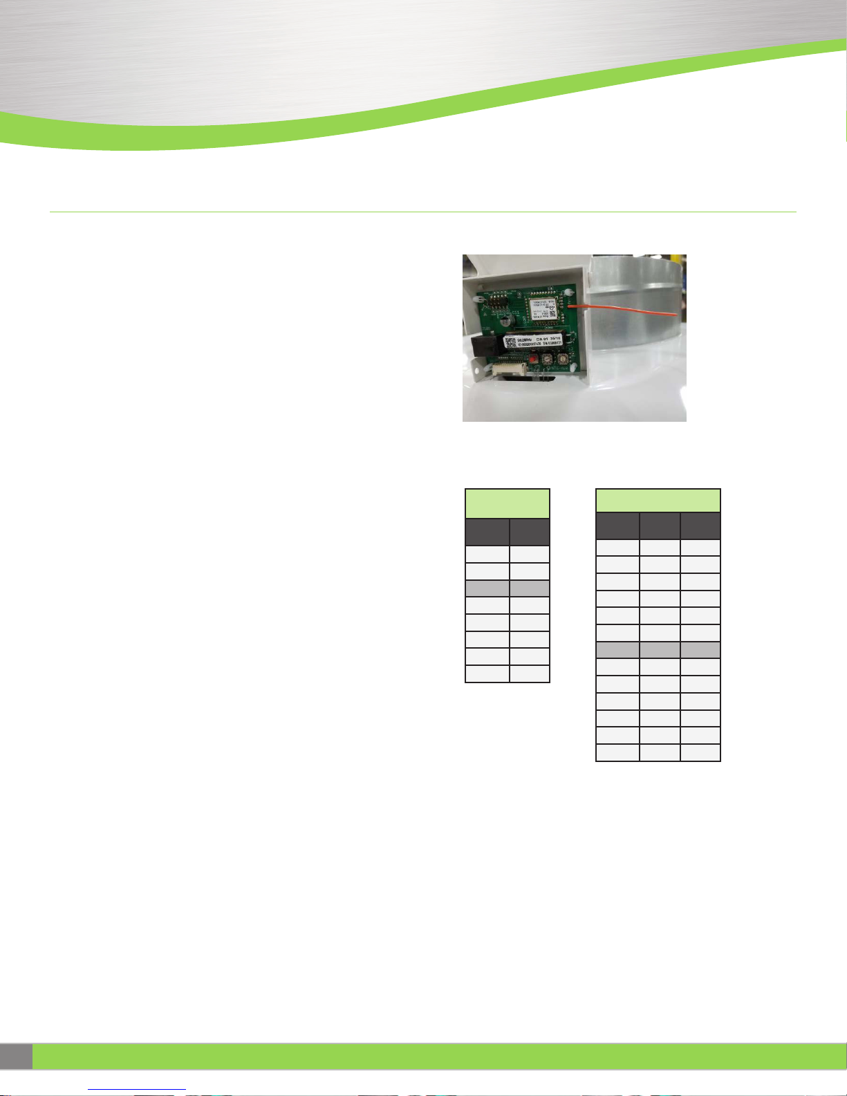
Standalone Commissioning
1. On the back pan, locate the control box and flip the cover open. Locate
the two rotary dial switches on the lower right corner of the control board.
Figure 6. Control Board Enclosure
2. The 10 position dial controls the minimum damper position setting and
the 16 position dial controls the heating and cooling temperature set
points. The tables below show the corresponding settings. Factory set
positions are indicated by shaded cells below.
3. When the desired settings are selected, press the red button on the
control board to read the new settings into memory.
4. To place the unit in maximum open position for airflow balancing, press
the red button 3 times in quick succession. The LED will blink 3 times.
The damper will be driven to full open position. The damper will stay in
this position for 1-1/2 hours before returning to normal operating mode. If
balancing is completed prior to this time, pressing the red button 1 time
will return the diffuser to normal operating mode.
10 Position
Dial Switch
Dial
Position
0 0
1 5
2 10
3 15
4 20
5 25
6 30
7 35
Minimum
Position
10 Position Dial Switch
Dial
Position
6, 7, 8, 9 75 72
Cooling
Set Point
0 69 66
1 71 68
2 73 70
3 75 72
4 77 74
5 79 76
A 69 64
B 71 66
C 73 68
D 75 70
E 77 72
F 79 74
Figure 7. Control Board Switch Settings
Heating
Set Point
4
IOM - HELIOS
Redefine your comfort zone. ™ | www.titus-hvac.com
Page 5

Troubleshooting
SELF-TEST PROCEDURE
1. Press the test button 4 consecutive times (4 short presses). This puts
the diffuser n self-test mode. The damper ring should move through a full
range of motion from (full open to full closed)
2. If there is no problem detected, the external led will be turn on and stay
on. The extension harness may now be disconnected.
3. If a problem is detected, the external led will blink in a pattern indicating
the type of error detected. Use the table below to troubleshoot possible
solutions.
BLINK
PATTERN
1x
2x
3x
4x
ERROR DETAILS POSSIBLE CAUSES CORRECTIVE ACTION
Solar current out of range
(light level measured at solar cell must be above
(increments prior to mechanical block exceed
100 lux)
Motor timeout error
limit)
Other motor errors
(no encoder increments detected)
Temperature out of range
(<=5BC or >=50BC)
(<=41BF or >=122BF)
Figure 12. Control Board Error Codes
SOLAR CELL DEFECT CHECK THAT SOLAR CELL IS CONNECTED. REPLACE SOLAR CELL IF NECESSARY.
LIGHT LEVEL BELOW 100 LUX CHECK THAT LIGHT SOURCE IS ON AND SOLAR CELL IS OVER THE LIGHT. ADJUST LIGHT SOURCE TO 100 LUX IF NECESSARY.
BOARD DEFECT REPLACE CONTROL BOARD
MOTOR OR WIRING DEFECT CHECK THAT THE MOTOR IS CONNECTED. REPLACE MOTOR IF NECESSARY.
MECHANICAL DEFECT REPLACE MOTOR
BOARD DEFECT REPLACE CONTROL BOARD
MECHANICAL UNIT BLOCKED CHECK FOR OBSTRUCTIONS ON ACTUATOR
MOTOR DEFECT REPLACE MOTOR
BOARD DEFECT REPLACE CONTROL BOARD
ROOM OR SUPPLY AIR
TEMPERATURE OUT OF RANGE
SENSOR DEFECT REPLACE ROOM TEMPERATURE SENSOR; REPLACE CONTROL BOARD
BOARD DEFECT REPLACE CONTROL BOARD
CHECK THAT ROOM TEMPERATURE SENSOR IS CONNECTED; CHECK THAT SUPPLY TEMPERATURE SENSOR IS NOT TOUCHING
DIFFUSER BACKPAN
Redefine your comfort zone. ™ | www.titus-hvac.com
IOM - HELIOS
5
Page 6

IOM
HELIOS
Theory of Operation
• The Helios diffuser is a self-powered variable geometry air distribution
device capable of maintaining temperature control in an occupied space
though digitally controlled VAV operation.
• A damper ring is vertically adjusted by a motorized lead screw which
varies air flow through the diffuser.
• The digital control circuitry and motor are powered by an energy storage
capacitor that is charge by a solar collection panel mounted in the plaque
face of the diffuser. After full charge the capacitor will maintain a charge
for 3 to 4 weeks
• The diffuser can be operated in three configurations:
• Standalone
• Single zone controlled by a wireless Helios wireless thermostat
• Multiple zone controlled by BACNET interface
Modes of Operation
Normal operating mode
Wakes every ten minutes to check:
• Capacitor charge level
• Light level- requires 100 Lux minimum (Average windowless office is about 130)
• Supply air and room temperature
Energy conservation mode - After 8 hours of low light (less than 100 Lux)
Maintains current damper position, wakes every ten minutes to check:
• Capacitor charge level
• Light level- requires 100 Lux minimum
Low Energy mode - capacitor charge drops below 2.8V
• Damper moves to full open
• 0 minute intervals between capacitor charge level check
6
IOM - HELIOS
Redefine your comfort zone. ™ | www.titus-hvac.com
Page 7

Notes
Redefine your comfort zone. ™ | www.titus-hvac.com
IOM - HELIOS
7
Page 8

605 Shiloh Rd
Plano TX 75074
ofc: 972.212.4800
fax: 972.212.4884
Redefine your comfort zone. ™ | www.titus-hvac.com
 Loading...