

Page 1
Installation Instructions
(Please see reverse side.)
FR-TDC/A-FR-II 2-28-13
FR-TMS/A-FR-II 2-28-13
FR-PAS-FR-II 2-28-13
FR-PCS-FR-II 2-28-13
FR-PSS-FR-II 2-28-13
FR-PAR-FR-II 2-28-13
5
6
3
4
7
8
2
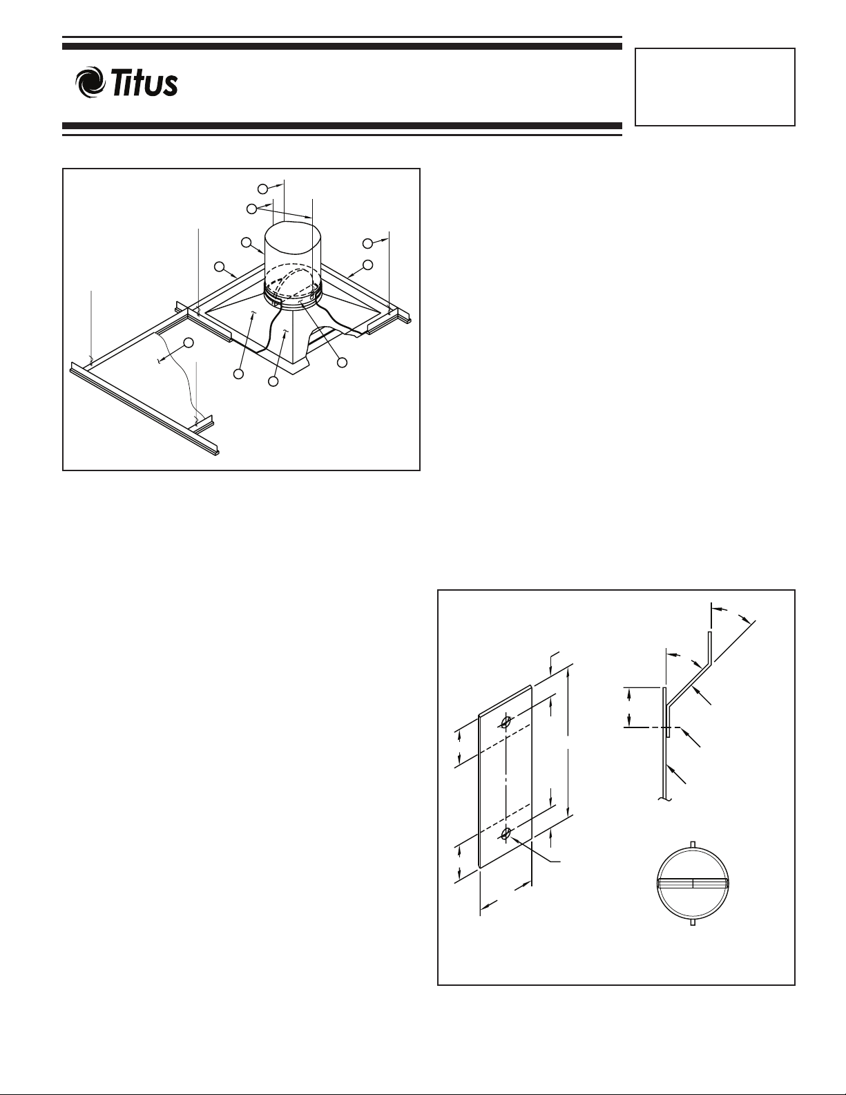
ITEM DESCRIPTION
1. Damper
2. Diffuser 24 Gauge Minimum
3. Flex Air Duct
4. Ceiling grid (UL Classified)
5. 12 Gauge Steel Wire
6. 16 Gauge Steel Wire
7. Ceiling Material (UL Classified)
8. Thermal Blanket Insulation Mineral Fiber or
Ceramic Fiber
General Installation
The four intersections of the cross-tees and main runners at the corners
of the grid module containing the diffuser, or the midpoint of the cross-
5
4
1
tees adjacent to the diffuser, shall be directly supported from the structural members of the floor or roof by 12 SWG minimum vertical hanger
wires. When the duct extends over the intersections of the grid
members, minimum No. 16 gauge, cold-rolled steel channels shall be
used to ensure that the grid is supported from structural members by 12
SWG minimum hanger wires. All UL Classified ceiling assemblies
require lay-in ceiling panels be cut to fill the remainder of the 24” x 48”
module and shall provide a minimum of 3/8” bearing on the ceiling grid
members.
A steel clamp of No. 16 SWG minimum steel wire shall fasten the flex
air duct to the damper when flex air duct is used to connect the main
duct to the damper. The flex air duct shall be Class 0 or Class 1 and
bear the UL Listing Mark. Refer to the UL Fire Resistance Directory
“Design Information Section — General” for installation requirements.
IMPORTANT: Screws, bolts, rivets, etc. used in connection of the
damper MUST NOT INTERFERE WITH DAMPER BLADE
OPERATION. Hanger wires
must be vertical and not splayed.
The damper must be fastened to the diffuser neck or grille frame in
installations 1, 2, 3, 4, and 5. The damper must also be fastened to the
duct drop in installation 2.
0
45
Min.
0
45
Bend
Line
3/8"
1"
3"
Hanger Strap
3/16" Diameter
Rivet
APPLICATION
Fire Resistance Classified Ceiling Air Diffusers are for use in lieu of
hinged-blade sheet metal dampers in steel ducts as specified in the
“Design Information Section — General” and in individual floor/ceiling or
roof/ceiling designs used as illustrated and described in the UL Fire
3/4"
Resistance Directory (FRD). When installed as shown and as described
herein, these ceiling air diffusers provide appropriate protection to
ceiling penetrations in any fire rated floor/ceiling or roof/ceiling assemblies with ratings of three hours or less as described in the FRD.
A maximum size ceiling penetration of 576 square inches can be
protected using the thermal insulating blanket furnished with the ceiling
air diffuser. The thermal insulating blanket protects the exposed
3/4"
Bend
Line
3/8"
3/16"
Typ.
Damper Frame
Hanger
Strap Location
portions of the ceiling diffuser and the ceiling damper protects the neck
or inlet of the ceiling diffuser.
All system components (ducts, duct drops, sleeves, diffuser pan, or
grille frames) must be constructed of steel. The installations and
diffusers shown in these instructions illustrate general arrangement
only. Installations must also incorporate any specific
requirements
included in the FRD. Note that both “Design Information Section —
1"
Min.
Detail of Hanger Strap
(Optional)
Damper Top View
(Location of Hanger Straps is
similar on Rectangular units)
General” and individual floor/ceiling or roof/ceiling design listings apply.
An adjustable damper must be installed in closed position with clearance between the diffuser and adjustment mechanism. Cycle the damper open
after the diffuser and damper have been completely assembled and clearance verified.
Page 2
3
7
8
9
10
1
8
14
2
12
5
6
X
7
9
13
8
10
14
2
4
1
5
5
6
X
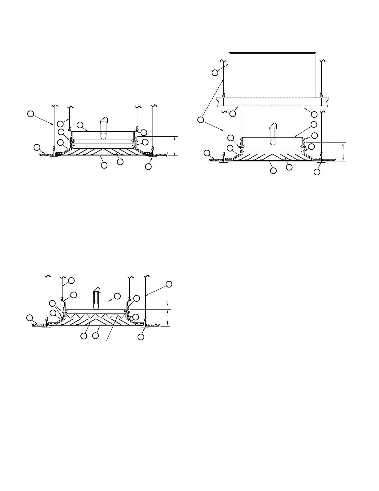
Installation 1
Ductless return or flex duct supply with
two support straps required
With steel duct for any size unit
Installation 2
UNIT DESCRIPTION
(Installations 1, 2, and 3)
1. Damper
2. Diffuser 24 Gauge Minimum
8
12
8
9
10
2
14
1
Volume Controller (optional)
11
5
6
7
1"
Max. 4 1/4"
Installation 3
For extended height assemblies
3. Duct
4. Duct Drop
5. #8 Sheet Metal Screw (see text)
6. Ceiling Grid (UL Classified)
7. No. 12 Gauge Steel Wire
8. No. 16 Gauge Steel Wire
9. Ceiling Material (UL Classified)
10. Thermal Blanket Insulation, Mineral Fiber or
Ceramic Fiber
11. Thermal Blanket Extension (3” wide), Mineral
Fiber or Ceramic Fiber
12. Hanger Strap
13. No. 16 MSG, 1
1
/2” Cold-Rolled Steel Channel
14. Diffuser Core (Metallic or Non-Metallic)
NOTE:
X Dimension — 4” maximum with 12” diameter (113 sq. in.) damper
and smaller.
3
/4” maximum with damper larger than 12” diameter
2
(113 sq. in.)
When extended height is required, see Installation 3.
2
Page 3

INSTALLATION 5
Four thermal insulating blanket strips are supplied. The strips are to be
laid between adjacent tee bars and the collar as depicted. No retaining
wire is required. All fasteners must be No. 8 sheet metal steel screws,
3
/16” tubular steel rivets, or 1/4” minimum tack welds. Use a minimum of
two connections per side for rectangular or square dampers and three
equally spaced connections for round dampers. Space fasteners a maximum of 6” apart. A maximum of 1/8” (1/4” total) clearance must exist
between the ceiling damper and diffuser or duct drop.
In each installation, all screw or rivet attachments shall be placed a minimum of
frame. All dampers must be supported by No. 16 SWG, 1 1/2” cold-rolled
steel channels adjacent to both sides of the duct drop with a No. 12
SWG vertical (not splayed) hanger wire at each end.
As an alternate, two hanger straps may be used with a No. 12 SWG
hanger wire support from each strap to structural members.
Hanger straps may be factory supplied (optional) or may be field fabricated from 1” wide x
Form as shown in Hanger Strap Detail. Fasten hanger strap to damper
frame using 3/16” tubular steel rivets. Rivets must not interfere with operation of the damper blades.
3
/16” from the edge of the damper frame, duct drop, or diffuser
3” long strips of No. 20 gauge galvanized steel.
4
5
3
6
7
2
5
4
3
8
1
6
6
9
5
6
7
3
8
1
Installation 4
Any Size Unit with
18 x 18 Neck Size and Smaller
5
8
7
1
ITEM DESCRIPTION
1. Damper
2. Diffuser (No. 24 Gauge Minimum)
2 3/4" MAX.
2
10
4
3. Ceiling Grid (UL Classified)
4. No. 12 Gauge Steel Wire
5. No. 16 Gauge Steel Wire
6. Ceiling Material (UL Classified)
7. Thermal Insulating Blanket
8. Hanger Strap
ITEM DESCRIPTION
(Installations 4 and 5)
1. Damper
2. Diffuser Frame (No. 24 Gauge Minimum)
3. #8 Sheet Metal Steel Screw (see text)
4. Ceiling Grid (UL Classified)
5. No. 12 Gauge Steel Wire
6. No. 16 Gauge Steel Wire
7. Ceiling Material (UL Classified)
3
2" max.
8. Thermal Blanket Insulation
9. Hanger Strap
10. Diffuser (Metallic or Non-Metallic)
4
10
2
CAUTION: Replace the thermal insulating blanket if it is damaged
Installation 5
during shipment or installation.
3
Page 4

FR-TDC/A-FR-II 2-28-13
FR-TMS/A-FR-II 2-28-13
FR-PAS-FR-II 2-28-13
FR-PCS-FR-II 2-28-13
FR-PSS-FR-II 2-28-13
FR-PAR-FR-II 2-28-13
Part # 719687-07
Note: This submittal is meant to demonstrate general dimensions of this product. The drawing on this submittal are not meant to detail every
aspect of the product with exactness. Drawings are not to scale. TITUS reserves the right to make changes without written notice.
All rights reserved. No part of this work may be reproduced or transmitted in any form or any means, electronic or mechanical, including photocopying and recording, or by any information storage retrieval system without permission in writing from Air Distribution Technologies.
605 Shiloh Road • Plano, Texas 75074 • 972- 212- 4800
 Loading...