

Page 1
INSTALLATION & OPERATION MANUAL
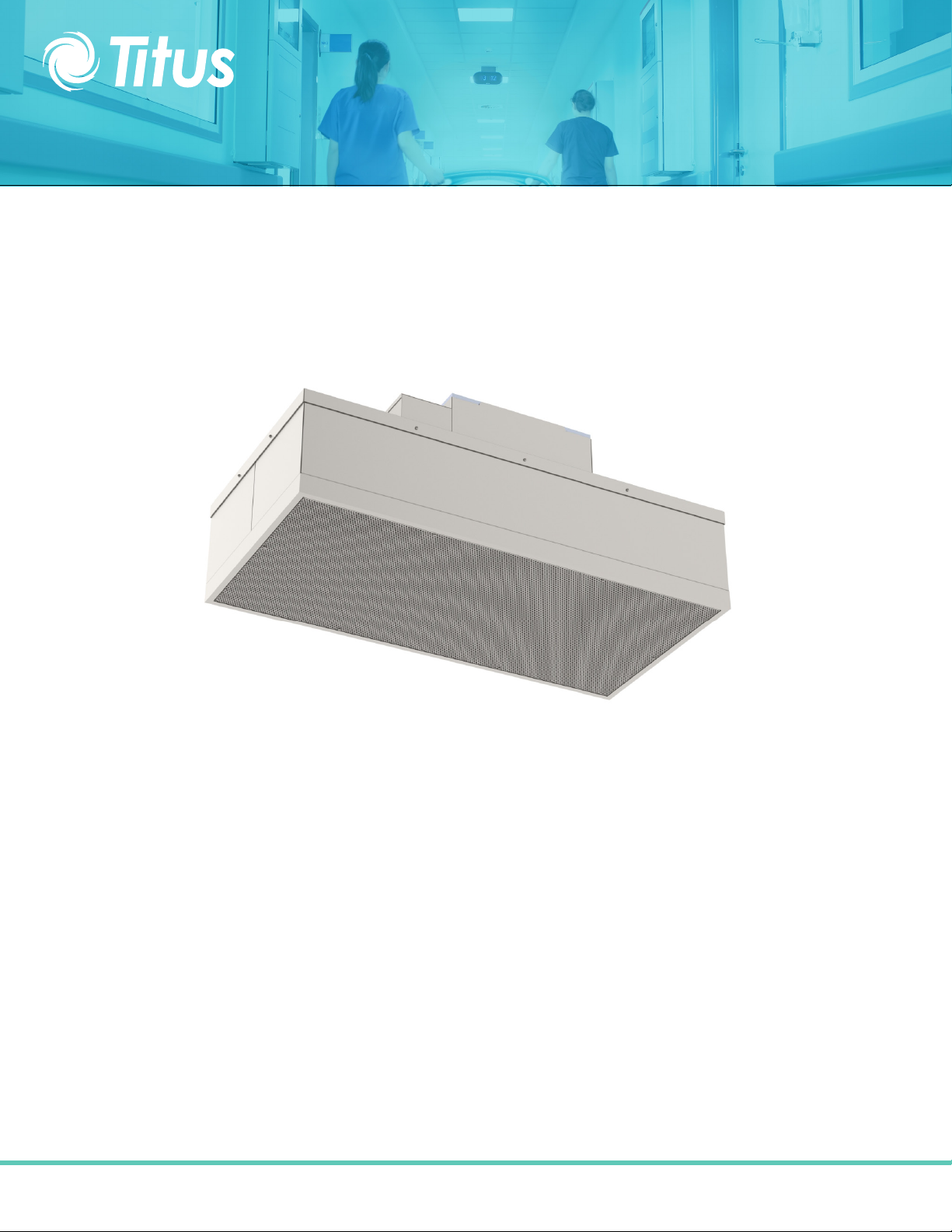
Fan Filter Unit
FFD, FFDR, & FFDRA Models
Page 2

INSTALLATION & OPERATION MANUAL
Table of Contents
Fan Filter Unit IOM
FFD, FFDR, FFDRA Models
Critical Operations of the Fan Filter Unit .......................................................................... 3
Warnings ................................................................................................................................. 3
Installation.............................................................................................................................4
ON/OFF Switch - Speed/Airflow Adjustment ....................................................................5
Troubleshooting.................................................................................................................6
Pre-filter Cleaning (foam) ..................................................................................................7
Service: Removal and Replacement of FFD Filters.............................................................8
Service: Removal and Replacement of Roomside Replaceable Filters ............................9
Service: FFD and FFDR Motor Removal and Installation .................................................10
Service: FFDRA Motor Removal and Installation .............................................................11
Unit Wiring Diagrams .......................................................................................................12
Unit Replacement Parts List ..............................................................................................13
Drawing - FFD Filter ..........................................................................................................14
Drawing - FFDR & FFDRAFilter .........................................................................................15
Testing...............................................................................................................................16
Installation & Operation
Page 3
Fan Filter Unit IOM
FFD, FFDR, FFDRA Models
INSTALLATION & OPERATION MANUAL
Critical Operation Conditions of FFD, FFDR, & FFDRA models
1. Touching of the HEPA filter will damage it, voiding the warranty on the filter. The screen is only to protect against an
accidental ‘touch’ of the filter. Never place a hand or tool on the filter. Never lie filter face flat down on a surface always
have filter on its side to protect from damage.
2. Prior to powering the unit, verify voltage on label and that the unit has been wired into the correct voltage. The serial
number label on the top of the unit has the required voltage.
3. To insure you order the proper replacement parts or complete unit, record the part number and serial number. This
information is located on the serial number label, located adjacent to the electrical box. If you can’t locate the Sales Order
Number, please contact Titus for this information. Once obtained, record the information for reference.
Warning
TO REDUCE THE RISK OF FIRE, ELECTRICAL SHOCK, OR INJURY TO PERSONS, OBSERVE THE FOLLOWING:
A. Installation work and electrical wiring must be done by qualified person(s) in accordance with all applicable codes and
standards, including fire-rated construction.
B. When cutting or drilling into wall or ceiling, do not damage electrical wiring and other hidden utilities.
C. If this unit is to be installed over an area using liquid, such as water or chemical cleaning solutions, it must be marked as
appropriate for the application.
D. Use this unit only in the manner intended by the manufacturer. If you have any questions, contact the manufacturer.
E. Before servicing or cleaning the unit, switch power off at unit service panel and lock service panel to prevent power from
being switched on accidentally.
Installation & Operation
3
Page 4
Fan Filter Unit IOM
FFD, FFDR, FFDRA Models
INSTALLATION & OPERATION MANUAL
Installation
Note: Titus fan filter units are completely assembled at the factory with the exception of the optional ¼”-20 eyebolts
that are used when hanging the unit from an engineered design support system and installation of the HEPA/ULPA filters
(eyebolts not included and can be ordered separately, p/n 222449-001).
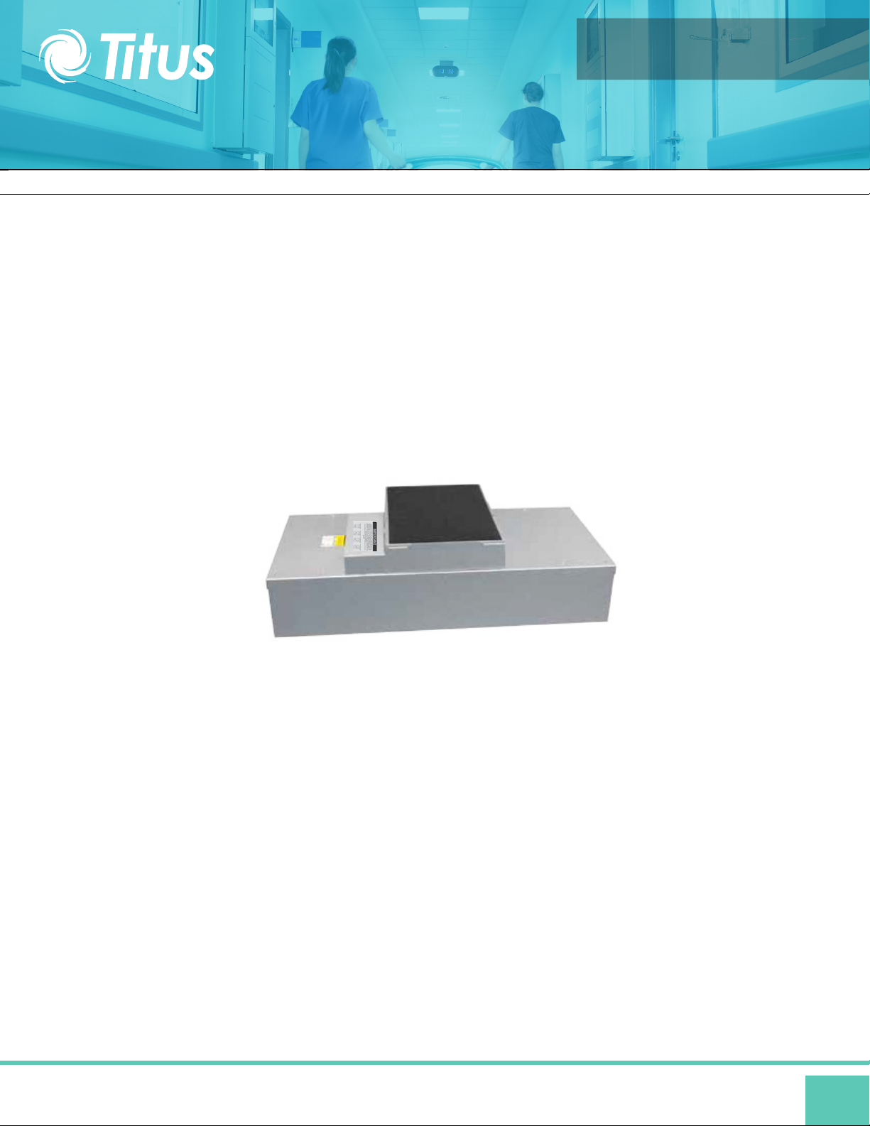
Step 1. Carefully remove the unit from the shipping carton and inspect for any damage that may have occurred during
transportation (See Figure 1).
Note: When ordering FFDR and
FFDRA units, the HEPA filters may
be shipped separately to be installed
into units after the fan box has been
installed.
Figure 1: Unboxing
If using rigidly supported grid (usually 2” (50 mm) or wider), raise unit through ceiling and lower onto the gasketed grid.
Step 2.
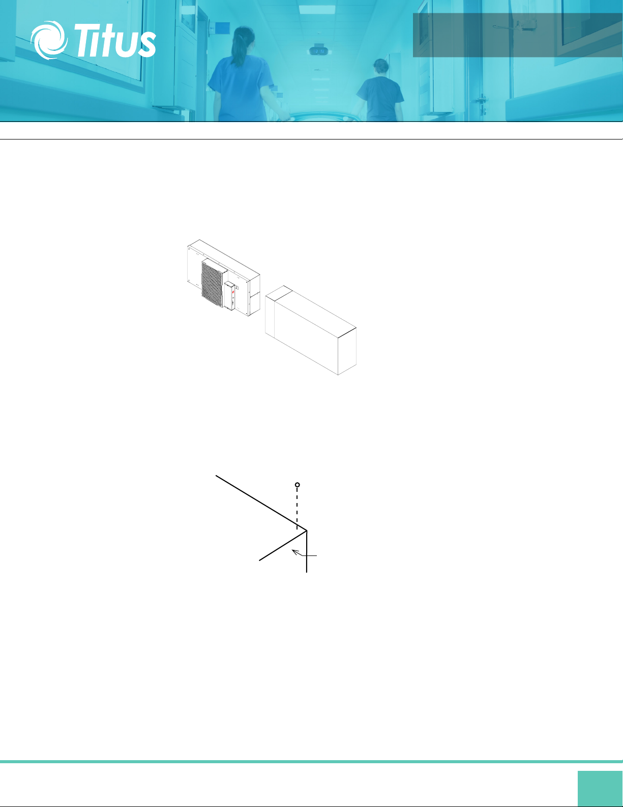
If using a flexible grid (typically supported with wires), the unit must be secured to an engineered design support system
with s-hooks and chain. Screw the four eyebolts into the nutserts on the lid assembly before lifting into an overhead position
(see Figure 2) Note: Confirm fan dimensions to match T-grid dimensions.
EYEBOLT
FAN FILTER
UNIT
Figure 2: Hanger Supports
Step 3. Raise the unit and secure it into place using the chosen support system method suspended from a structural support
bracing.
Step 4. Have an electrician wire the unit to the appropriate voltage, according to the wiring diagram (page 17), and all national
and local electrical codes. All units are equipped with a three position terminal block for field onnection. Verify correct singlephase
power, before energizing units.
Step 5. Turn on the power using the two position rocker switch (ON/OFF) located on the electrical box. For FFDR and
FFDRA units, let the unit run for a few hours to purge off particulate (if filters are shipped loose) that may be adhered to
the inside of the unit before installing the filters. Do not run fan at full speed as this may cause overload condition.
Note: Your fan filter may have been shipped separate. Controls have been shipped separately.
Installation & Operation
4
Page 5
INSTALLATION & OPERATION MANUAL
ON/OFF Switch - Speed/Airflow Adjustment
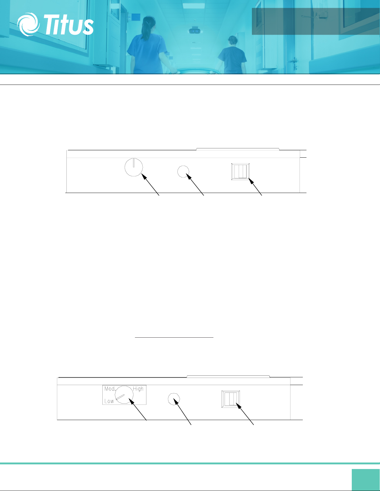
All units are equipped with a speed control enabling adjustment of airflow at any setting
within the recommended performance range. The speed control knob is located on the
side of the electrical box, adjacent to the on/off switch.
Fan Filter Unit IOM
FFD, FFDR, FFDRA Models
ON/OFF SwitchElectrical EntranceSpeed Control
Speed Control Adjustment
Airflow/speed is adjusted by rotating the knob (See figure above):
Clockwise Lowers the speed
Counter-Clockwise Increases the speed
Fully rotating the speed control knob to the left or counter-clockwise will turn the unit off.
Note : When turning the unit “ON” from the “OFF” position of the speed control, the fan
is at the highest speed. Turning the speed control knob clockwise will lower the airflow.
Optional Speed Control
For units equipped with a three-position rotary switch, it is located on the side of the
electrical box. (See figure below)
Recommended fan speed during initial start-up and operation is the “LOW” speed. As
airflow eventually decreases due to filter loading, fan speed may be increased by
moving the rocker switch to the top or “MEDIUM” position, and finally to the “HIGH”
position. Periodic airflow velocity readings (per IEST Reccommended Practices)
should be conducted to determine the filter condition and appropriate fan speed
setting.
ON/OFF SwitchElectrical Entrance3-Speed Switch
Installation & Operation
5
Page 6

Fan Filter Unit IOM
FFD, FFDR, FFDRA Models
INSTALLATION & OPERATION MANUAL
Troubleshooting
Low Air Velocity:
Step 1. Adjust variable speed control for higher blower output. For units eqquped with 3-speed, adjust switch setting from
“LOW” to “MEDIUM” to “HIGH”.
Step 2. Check prefilter media; replace or clean as necessary.
Step 3. Check incoming power supply for proper voltage (120,208-240,277/24).
Step 4. Examine the HEPA/ULPA filter.
High Air Velocity:
Step 1. Adjust variable speed control for lower blower output. For units eqquped with 3-speed, adjust switch setting from
“HIGH” to “MEDIUM” to “LOW”.
Filter Issues:
Non-Laminar Flow and/or Excessive Contamination:
Step 1. Insure that no large obstructions are upstream of airflow pattern.
Step 2. Determine that no other air-moving devices are operating in or around clean room which disrupt room’s
airflow pattern.
Step 3. Check air velocity and if low, conduct the “Low Air Velocity” procedure outlined above.
Step 4. Conduct smoke and photometer test on HEPA/ULPA filter. Seal or replace HEPA filter as necessary.
Installation & Operation
6
Page 7

Fan Filter Unit IOM
FFD, FFDR, FFDRA Models
INSTALLATION & OPERATION MANUAL
Cleaning the Pre-filter (foam)
Tools Required: None.
Note: To keep the filter in top operating condition, washing
the foam prefilter is recommended every three to six months.
Step 1. To gain access to the prefilter, remove the ceiling
panel next to the unit, if applicable.
Step 2. Switch the ON-OFF switch to the off position.
Step 3. Remove the 16”x23” prefilter from the snap-in frame. (See figure below)
Step 4. Clean the prefilter by hand washing in water with a mild detergent or by using a vacuum cleaner . Allow prefilter to
dry completely before replacing.
Step 5. Reassemble by reversing the above steps.
DISCONNECT THE UNIT FROM THE ELECTRICAL
POWER SOURCE BEFORE ATTEMPTING
WARNING
ANY SERVICE
ON/OFF SWITCH
PREFILTER SURFACE ON TOP SIDE
SUPPORT SCREEN ON BOTTOM SIDE
Installation & Operation
7
Page 8

Fan Filter Unit IOM
FFD, FFDR, FFDRA Models
INSTALLATION & OPERATION MANUAL
Service: Removal and Replacement of FFD HEPA/ULPA Filters
WARNING
WARNING
DISCONNECT THE UNIT FROM THE ELECTRICAL
POWER SOURCE BEFORE ATTEMPTING
ANY SERVICE
Note: All filters should be visually inspected for freight damage before installation. It is necessary to use two workers when
removing the filter and for installation to avoid twisting or separation of the media seals. Handle the filter only by the frame
and never place anything on the upstream filter side of the filter. Additionally, it is important to keep the filter level to prevent
any shearing force on the media itself.
For Standard Filters:
Tools Required: Phillips Head Driver, Battery Operated Drill with 5/32 drill bit, Rivet Hand Tool, Ø5/32 aluminum rivet grip
range.126-.187
Step 1. Remove unit from ceiling.
Step 2. Remove the 10 screws holding the HEPA/ULPA filter to the lid assembly.
Step 3. Lift the lid assembly off the HEPA/ULPA filter (see figure). Remove filter deflectors using 5/32 drill bit. Keep filter
deflectors to install in new filter. Discard the used filter as per requirements of the applicable regulations. Carefully install the
filter deflectors into the new filter using the 5/32 rivets. Do not touch or place the filter deflectors on the HEPA/ULPA media
pack. This could cause tears in the filter pack.
Step 4. Before replacing with the new filter, carefully inspect the new filter for any visible damage. Also inspect the gasket
and the T-Bar to insure a tight seal. Replace if necessary.
Step 5. To replace a filter, raise the filter and rotate into position in the ceiling grid (with power off), then lower the plenum
housing into place. Reconnect wiring and hardware from previous steps that have been removed.
Step 6. Restore power and verify proper operation of FFU.
THE STANDARD FILTER IS PROTECTED WITH AN
EXTENDED METAL FACE SCEEN. THIS IS NEVER TO
BE USED TO HANDLE THE FILTER. IT IS ONLY FOR
PROTECTION AGAINST AN ACCIDENTAL TOUCH
OF THE FILTER. ONLY HANDLE THE FILTER BY THE
FRAME
Electrical Knock Out
Filter Deflector
HEPA/ULPA Filter
Standard Filter Change
On/Off Switch
Lid Assembly
#8 Screws (10x)
Ø5/32 Rivet (6x)
Installation & Operation
8
Page 9

Fan Filter Unit IOM
FFD, FFDR, FFDRA Models
INSTALLATION & OPERATION MANUAL
Service: Removal and Replacement of FFDR & FFDRA Filters
WARNING
WARNING
DISCONNECT THE UNIT FROM THE ELECTRICAL
POWER SOURCE BEFORE ATTEMPTING
ANY SERVICE
Note: All filters should be visually inspected for freight damage before installation. It is necessary to use two workers when
removing the filter and for installation to avoid twisting or separation of the media seals. Handle the filter only by the frame
and never place anything on the upstream filter side of the filter. Additionally, it is important to keep the filter level to prevent
any shearing force on the media itself.
For FFDR & FFDRA Filters:
Tools Required: Phillips Head Driver, Battery Operated Drill, 3/16” hex head ball driver (2ea)
Step 1. With the power off, remove the diffuser screen by removing the 6 each 10-32x1/2 screws, then carefully place in a
safe location.
Step 2. Loosen the six 1/4x12 socket head screws far enough to rotate the eight filter clips 90°. The filter may be loose
enough to drop during this operation. If not, slowly pull the filter away from the knife-edge seal, taking care not to touch the
filter face during this operation. It is important to pull the filter slowly away from the seal, so that the gel remains in the filter
gel track.
Step 3. Carefully clean plenum assembly knife edge surface of residual gel material.
Step 4. Inspect filter for visible damage, if damaged set aside for replacement or repair.
Step 5. Inspect the gel seal, if reinstalling the removed filter. Determine if the gel has lost its ability to seal (i.e. the gel should
reform to cover the track without voids or openings), if so repair the gel material or consider replacement of filter.
Step 6. Place the filter evenly against the filter-sealing surface of the unit. Reposition filter clips and screws. The clips
should be rotated and angled into place. It is recommended that four workers work on each corner of the filter
simultaneously, holding the filter seated into the track. Hand tighten clips from opposite corners evenly until all clamps are
tightened.
Step 7. Reinstall diffuser screen by hand-tightening the screws.
Step 8. Determine if recertification or testing of replacement is required.
Step 9: Restore power to FFU and verify proper operation of FFU.
Fan Filter Unit
THE STANDARD FILTER IS PROTECTED WITH AN
EXTENDED METAL FACE SCEEN. THIS IS NEVER TO
BE USED TO HANDLE THE FILTER. IT IS ONLY FOR
PROTECTION AGAINST AN ACCIDENTAL TOUCH
OF THE FILTER. ONLY HANDLE THE FILTER BY THE
FRAME
Filter
2-Piece Welded
Plenum Housing
Filter
Knife- Edge
Seal
Gel Track
Filter Clip and
Screw (typ 6)
Diffuser Screen
Screws (typ 6)
FFDR & FFDRA Filter Change FFDR & FFDRA Filter Replacement
¼ -20
Cap
Screw
10-32
PHP
Screws
Filter Clip
Installation & Operation
Diffuser
Screen
9
Page 10

INSTALLATION & OPERATION MANUAL
Service: FFD and FFDR Motor Removal and Installation
Fan Filter Unit IOM
FFD, FFDR, FFDRA Models
WARNING
DISCONNECT THE UNIT FROM THE ELECTRICAL
POWER SOURCE BEFORE ATTEMPTING
ELECTRICAL SERVICE SHOULD ONLY BE PERFORMED
BY A LICENSED OR QUALIFIED ELECTRICIAN
WARNING
ANY SERVICE
Tools Required: Phillips Head Driver, Battery Operated Drill, (2) 8” adjustable wrenches, 10 mm hex head wrench,
#2 screwdriver, and slip joint pliers.
Step 1. To gain access to the motor, remove the ceiling panel next to the unit, if applicable.
Step 2. Switch the ON-OFF switch to the off position.
Step 3. Loosen the electrical box cover screws (2), and slide/lift off cover.
Step 4. Make note of all wire routing and locations for later reinstallation.
Step 5. Disconnect the two brown wires from the capacitor, using a pair of pliers. Disconnect the motor wiring from the rotary switch and rocker
switch or speed control and rocker switch and remove the grommet from the motor leads. Save this grommet for reinstallation.
Step 6. Remove the eight mounting screws to free the motor/blower assembly from the lid assembly. If using power drivers,
set the unit to a low torque setting to avoid stripping the sheet metal screws. Carefully remove housing assembly, paying
attention to wire routing.
Step 7. Using an adjustable wrench loosen the two set screws that attach the blower wheel to the motor shaft.
Step 8. Mark the location of the motor support bracket (belly band), then loosen the bolt just enough to allow the motor
support bracket to slid off the motor.
Step 9. Using the removed motor, mark the new motor with the location of the motor support bracket.
Step 10. Replace with the new motor and reassemble by reversing the above steps 1-8. Set the spacing at 0.25” (6.35 mm)
clearance between the blower and the upper motor plate/prefilter frame. This will give a 0.11” overlap between the venturi
ring and the blower.
Prefilter
Power Entrance
Motor/Electrical Removal
Motor
Venturi Ring
Blower Wheel
ON/OFF Switch
Installation & Operation
10
Page 11

INSTALLATION & OPERATION MANUAL
Service: FFDRA Motor Removal and Installation
Fan Filter Unit IOM
FFD, FFDR, FFDRA Models
WARNING
DISCONNECT THE UNIT FROM THE ELECTRICAL
POWER SOURCE BEFORE ATTEMPTING
ELECTRICAL SERVICE SHOULD ONLY BE PERFORMED
BY A LICENSED OR QUALIFIED ELECTRICIAN
WARNING
ANY SERVICE
Note: Minimum 2 person project.
Tools Required: 3/16 Ball Driver, Phillips screw bit, Head Driver, Battery Operated Drill, (2) 8” adjustable wrenches, 10 mm
hex head wrench, #2 standard screwdriver, and slip joint pliers.
Step 1. To gain access to the motor, remove the gel seal filter.
Step 2. Prior to removing motor/blower assembly, remove blower wheel to expose motor connectors on motor. Using an
adjustable wrench loosen the two set screws that attach the blower wheel to the motor shaft. Disconnect the two brown wires from
the capacitor, using a pair of pliers. Disconnect the motor wiring from the rotary switch and rocker switch or speed control and rocker
switch and remove the grommet from the motor leads. Save this grommet for reinstallation.
Step 3. While supporting the motor blower assembly from below, remove the six screws on the underside of the venturi ring
and lower the assembly. (See Figure 7). Note the baffle does not have to be removed to remove the motor/blower assembly.
Step 4. Before removal of the motor mount bracket, measure the precise location of the bracket on the motor. Remove the
bracket.
Step 5. Replace with the new motor and reassemble by reversing the above steps. Set the location of the motor mount
bracket as measured (see above Step 6). Set the spacing at 0.25” (6.35 mm) clearance between the blower and the upper
motor plate/prefilter frame creating a 0. 1” (2.80 mm) overlap between the wheel and the venturi ring. When reinstalling the
assembly, align the plate to insure that the leads will reach the electrical box.
Electrical connectors
located in inner
prefilter wall
Grommet
Plenum
Motor/Blower
Assy
Baffle Assembly
Gel Seal Filter
Screen
Motor/Electrical Removal
Motor Assembly
Machine Screw
Motor
Wellnut
and washer
Venturi
Ring
Blower
Wheel
Installation & Operation
11
Page 12

Wiring Diagrams
Fan Filter Unit IOM
FFD, FFDR, FFDRA Models
INSTALLATION & OPERATION MANUAL
Three Speed Wiring Diagram
Speed Control Wiring Diagram
Pressure Monitor Switch)
Network Control Card Wiring Diagram
Installation & Operation
12
Page 13

Replacement Parts List
Fan Filter Unit IOM
FFD, FFDR, FFDRA Models
INSTALLATION & OPERATION MANUAL
Model
FFD FFDR
FFDRA
FFD FFDR PSC Motor/Blower Assembly (FFD & FFDR)
Size/Voltage
N/A Disconnect Switch 63739-002
N/A Pre-filter (foam) 62981-001
N/A Deflector - Filter 38532-001
N/A Gasket, Neop .125x.5 62968
N/A Grommet 5/8 Id 1 1/8 Od 63388
120V
208V-240V
277V
120V
208V-240V
277V
230V Speed Controller (CE Marked) 63742
N/A
N/A
120V 64083-001
208V-240V 64083-002
277V 64083-003
120V 24332-001
208V-240V 24332-002
277V 24332-003
120V 24332-015
208V-240V 24332-016
277V 24332-017
Network Control Card (FFD, FFDR, & FFDRA)
PSC Motor/Blower Assembly (FFDRA)FFDRA
Description Part Number
Transformer 24V
Speed Controller
Blower Wheel
Ventiri Ring
63677
63666
63665
63011
63015
63016
63270
62964
Installation & Operation
13
Page 14

FFD Filter Drawing
Fan Filter Unit IOM
FFD, FFDR, FFDRA Models
INSTALLATION & OPERATION MANUAL
Installation & Operation
14
Page 15

FFDR and FFDRA Filter Drawing
Fan Filter Unit IOM
FFD, FFDR, FFDRA Models
INSTALLATION & OPERATION MANUAL
Installation & Operation
15
Page 16

Fan Filter Unit IOM
Recommended Testing – 8 readings with a Velgrid
FFD, FFDR, FFDRA Models
INSTALLATION & OPERATION MANUAL
Testing
Each fan filter unit is thoroughly tested at the factory before shipment. However, because of the “rigors” of
shipping, Titus encourages units are re-tested after installation.
Titus recommends that the customer contact an independent organization, with technicians trained
and experienced in performance evaluation and maintenance of clean air equipment.
HEPA filters (Type J) are tested to IEST-RP-00034. ULPA filters are tested to (Type F) IEST-RP-00034. All filters
are UL 900 recognized. Your filters may have special requirements, please see original engineering specifications
for you specific project.
All units that are airflow tested at Titus are tested using a Shortridge Airdata Multimeter 870 with a Velgrid head.
The recommended method of reading is to place one corner of the Velgrid head 1-1/4” from the corner of the
filter face and then take four reading evenly spaced along the four foot side, then repeat these reads three
additional times. This gives a total of 8 reading to test the unit. All advertised data is based on using the Velgrid
with 8 readings (128 velocity points). Titus recognized the using 8 reading during a cleanroom start-up may be
time consuming and recommends using 4 Velgrid readings taken on each 2x2 filter section will approximate the
same as 8 readings.
Recommended Testing – 8 readings with a Velgrid
Additional independent testing on the Titus fan filter units show that using one-2x4 or two-2x2 hoods
simultaneously give airflow data (cfm) with 5 percent of a duct traverse using 10 diameters of straight duct
upstream of the fan intake.
Installation & Operation
16
 Loading...