

Page 1
TU-FB-IOM 08-26-13
Fan Powered Terminals VAV Terminals
Receiving Inspection
After unpacking the terminal, check it for
shipping damage. If any shipping
damage is found, report it immediately
to the delivering carrier. Store units in a
clean dry location and do not stack more
than four high.
Caution: Do not use the inlet collar,
damper shaft, flow sensor or air
tubing as a handle to lift or move
assembly. Damage to the unit or
controls may result.
Before installation, remove fan packing
and all foreign material from the unit.
Check the blower wheel
for free rotation.
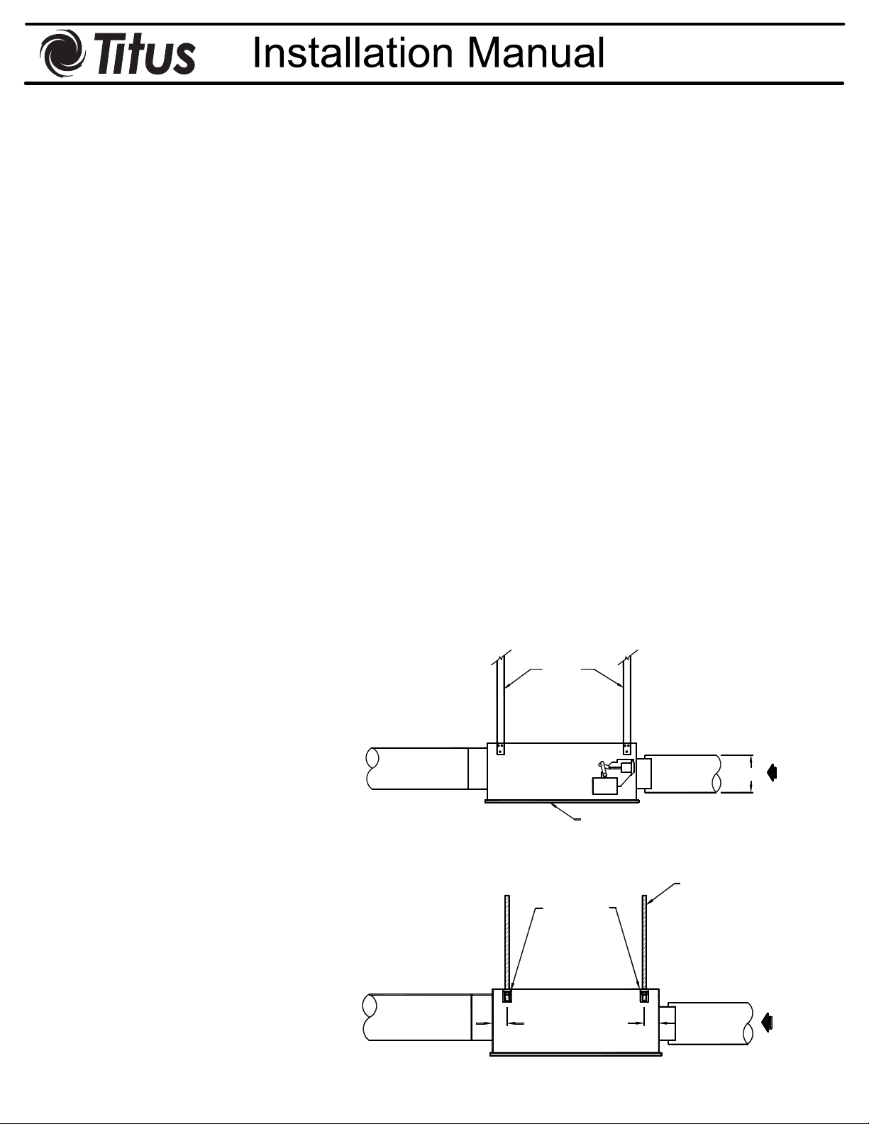
Supporting the Assembly
Suspend the unit from the building
structure in a horizontal plane with the
access panels facing downward.
Do not obstruct the access panels
with support channels or straps.
One inch long sheet metal screws can
be used to penetrate the casing (see
Figure 1). Use the support method
prescribed for the rectangular duct on
the job specifications. Unit may be
equipped with optional hanging brackets
(see Figure 2). Hanger rod up to 7/16"
diameter may be used.
The diameter of the inlet duct “D” in
inches must
be equal to the listed size of
the terminal; e.g. a duct that actually
measures 8 inches must be fitted to a
size 8 terminal. The inlet collar of the
terminal is made 1/8" smaller than listed
size in order to fit inside the duct (see
Figure 1).
Important: Do not insert duct work
inside the inlet collar of the
assembly.
Inlet duct should be installed in
accordance with SMACNA guidelines.
Rectangular discharge opening is
designed for flanged duct connections.
Fasten and seal
by method prescribed
in the job specification.
If single-point electronic velocity sensor
is used, 3 to 5 inlet duct diameters of
straight duct should be provided at the
terminal inlet.
Minimum Access
Fan Powered terminals require sufficient
clearance to service the fan blower
assembly and internal actuator (if so
equipped) from the bottom of the unit,
Straps
low voltage controls from the side of the
unit, and line voltage motor controls or
electric heat section (if so equipped)
from the rear or discharge of the unit.
For bottom access panel removal, 3"
minimum vertical clearance below the
unit is required, plus sufficient horizontal
clearance to slide the access panel clear
of the bottom of the unit. Horizontal
clearance is dependent on access panel
dimensions as indicated on product
submittals.
For low voltage control enclosure
access, a minimum of 18" is
recommended. Specific control
enclosure location is indicated on
product submittals. Panel for low voltage
enclosures are removable (not hinged).
For line voltage motor controls or electric
heat control access, a minimum
of 36"
should be provided to allow full opening
of hinged access doors. Specific location
is indicated on product submittals.
Important: These recommendations
do not preclude NEC or local codes
that may be applicable, which are
the responsibility of the installing
contractor.
Note: If equipped with pneumatic
control
s, or unit is parallel fan type
(Model TQP or FLP), the terminal must
Discharge
D
be mounted right side up. It must be
level within ±10 degrees of horizontal,
both parallel to the air flow and at the
right angle of air flow. The control side of
the terminal is labeled with an arrow
Figure 1.
Access Panel
(Entire Bottom is
Removeable)
indicating UP.
Hanger Rod
Duct Connections
Slip each inlet duct over the inlet collar
Optional
Hanger
Bracket
of the terminal. Fasten and seal the
connection by the method prescribed by
the job specification.
Discharge
1 1/2"
1 1/2"
Figure 2.
This IOM is meant to demonstrate general product details. The drawings are not meant to detail every aspect of the product. Drawings are not to scale. Titus reserves the right to
All rights reserved. No part of this work may be reproduced or transmitted in any form or by any means, electronic or mechanical, including photocopying and recording, or by any information storage retrieval s ystem without permission in writing from Air Distribution Technologies.
make changes without written notice.
Air
Flow
Air
Flow
1 of 9
Page 2
TU-FB-IOM 08-26-13
Field Wiring
All field wiring must comply with the
local codes and with the National
Electrical Code (ANSI/NFPA 70-1996).
Disconnect switches are optional
equipment. Electrical, control, and piping
diagrams are shown on the exterior
labeling or on a diagram on the inside of
the control and high voltage enclosure
covers. Unless specified otherwise in
the order write-up, all units are wired for
a single point electrical connection to the
fan and optional electrical heater. All
electric heaters if provided by TITUS are
balanced by kW per stage. The installing
electrician should rotate incoming
electric service by phase in order to help
balance the building electric load.
Caution—Electrical Requirement:
1. Provide a safety disconnect per
NEC 424-19, 20 & 21.
2. Disconnect all incoming power
before wiring or servicing unit. All
disconnect switches on the terminal
(if so equipped) should be in OFF
position while making power
connections.
3. All field wiring must be in
accordance with NEC and local
code requirements. All units with
electric heat should have copper
wires for 125% of Nameplate
Amperage.
4. Observe wiring diagram and
instructions mounted on the unit.
480 V/3 phase units require a 4th
(neutral) wire in addition to the full
sized ground wire. All units must be
grounded as required by NEC 42414 and 250.
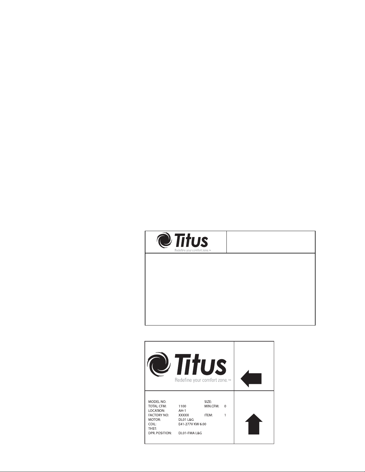
Unit Labeling
Each unit will have two main labels
attached to the casing. The FAN UNIT
label (Figure 3) lists the Model Number,
Supply Voltage requirements, Motor
Horsepower, and Overcurrent Protection
requirements. The AIR FLOW label
(Figure 4) lists the Model Number, Unit
Size, Factory Order Number, and
Location. The Location (or "Tag")
indicates the engineer's planned
location for the unit to be installed.
There may be other labels attached to
the unit, as options or codes may
require.
Control Start-up, Operation
Detailed information regarding power,
accessory and communications
connections, start-up and operating
procedures for the TITUS TD-1
controller (digital) or pneumatic and
analog controls are available from your
local TITUS representative. For specific
information on controls by other
manufacturers contact that
manufacturer’s local branch or dealer.
Note: Controllers may incorporate
specific communication addresses
based on Building Management
Systems Architecture, and original
engineering drawings. Installing the
terminal in a different location than
noted on unit label may result in
excessive start-up labor.
Primary Air Damper
TFS, TQS and TQP Models:
To replace
a. Disconnect power before servicing.
the damper blade and/or
shaft assemblies:
Remove control enclosure cover to
access actuator.
MODEL NO.: DTFS CODE: 88-XXXXX-A 2 REV: 02
MOTOR VOLT: 277 PHASE: 1 HZ 60
HP: 1/4 FLA(EA) 1.4
HEAT VOLT 277 PHASE 1 HZ 60
KW 6.0 AMPS 21.66
MOTOR (S) ARE THERMALLY PROTECTED
MIN. SUPPLY CIRCUIT AMPS: 24 AMP
MAX. FUSE OR OVERCURRENT PROTECTION: 30 AMP
MAX. OUTLET AIR TEMPERATURE: 200F
UNIT DESIGNED TO OPERATE AT NO LESS THAN 0.2 IWG STATIC PRESSURE
ZERO CLEARANCE FROM UNIT, CONNECTED DUCT AND/OR PLENUM
TO COMBUSTIBLE MATERIAL
Figure 3. FAN UNIT Label
DTFS
b. Note position of damper shaft, using
indicating arrow. Loosen linkage or
actuator collar to allow damper to
rotate freely.
c. Remove bottom access door to
expose damper assembly. Rotate
damper to fully closed position,
exposing rivets holding damper
blade to shafts.
d. Drill out rivets using 1/2” drill, rotate
damper to fully open position, and
slide damper and/or shaft
assemblies out of the duct.
e. Fit new damper and/or shaft
assemblies in place, using 1/4-20
screws with lock nuts to replace
rivets.
everse procedure in steps c, b,
f. R
and a, for assembly. When locking
down actuator linkage or collar,
position indicating arrow on damper
in the same location as before the
repair.
FLS and FLP Models:
These units use an opposed blade
damper assembly that is not repairable.
The entire assembly must be replaced.
FAN UNIT
AIR
FLOW
C12
UP
Please read all labels on a typical
unit, before beginning installation. If
you have any questions, please contact
the local TITUS Representative for
clarification. Have the key points from
the Air Flow label available for reference
before calling.
303155001015
Figure 4. AIR FLOW Label
2 of 9
Page 3

TU-FB-IOM 08-26-13
Standard PSC Motor Fan Flow
Adjustment
Note: Before starting fan motor, follow
steps 1 and 2.
1. Discharge ductwork should be
connected. The minimum
recommended discharge static
pressure is 0.2" wg. Be sure fan
packing is removed from units with
fan packing!
2. All foreign materials should be
removed from duct system. Filters
should be installed where required.
3. Standard PSC motors are shipped
from factory at full speed setting.
Allow motor to run-in at least 15
minutes before adjusting speed.
During initial run-in, check ductwork
connections for leaks and repair if
necessary. (Do not adjust fan speed
down if ductwork is not connected).
4. Unit is equipped with manual fan
speed control, mounted on the
bottom of the line voltage motor
enclosure or electric heat
enclosure. Turning the control
counterclockwise will reduce the fan
speed; clockwise will increase
speed.
5. Set the unit to full heating
(maximum induction). Adjust and
set remote balancing dampers, if
present. Adjust the speed control to
deliver the required CFM by
measuring air quantity at the room
outlets.
6. Proceed to primary air adjustment
procedure, detailed in control
installation information. Fan should
be re-adjusted with primary air and
ventilation air at maximum setpoint,
to insure that no supply air is
discharged at the induction port.
Maintenance Procedures:
Fan and Motor
Motor is equipped with permanently
lubricated bearings. Inspect fan and
motor assembly for accumulation of dust
and dirt as required by operating
environment. Clean as necessary.
If fan motor does not run:
a. Free rotation of blower wheel fan
packing removed. Freight or
installation damage.
b. Check for proper unit power
Disconnects should be ON .Check
optional fusing.
c. Check for proper control signal, P/E
switch setting, proper air control 24
Vac at fan contactor, coil energized.
If fan motor runs, excessive noise:
a. Clearance problems on blower. All
components securely attached.
b. Verify integrity of ductwork. Leaks
or loose connections. Rattling
diffusers or balancing dampers.
c. Maximum CFM too high, or
discharge static pressure too low
If fan motor runs, insufficient air flow:
a. Check for ductwork restrictions.
Dirty air filters. Clogged water coils.
b. Re-adjust fan spee d control.
c. Discharge static pressure too high.
If repair or replacement is required:
Motor and fan should be removed as an
assembly. Disconnect all power
before servicing. Remove the hex
nuts from the mounting lugs holding
the fan assembly to the discharge
panel, and lower the assembly. For
model TFS, lift the motor / blower
assembly to release the tabs from
the discharge panel, then lower the
assembly. Do not allow assembly to
hang from wiring.
Optional Water Coil Cleaning
In most cases, the supply side of the
water coil (optional) can be cleaned by
removing the bottom access door and
cleaning the coil face through the open
space between the motor / blower
assembly and the unit casing.
If more space is desired to clean the
water coil, the motor / blower assembly
may be removed and reinstalled as
described above.
If removing motor from blower, first
loosen the set screw holding the
blower wheel to the motor shaft.
Remove the three screws holding
motor to the fan housing, and slide
motor and fan housing apart.
Reverse the procedure for assembly.
Note: Over tightening motor mounting
screws may crush isolation bushings,
causing excessive fan noise.
3 of 9
Page 4

ECM Overview and Setup
TU-FB-IOM 08-26-13
Overview
This section addresses the Titus ECM motor which is
optional on all Fan Powered Terminal units. The ECM
motor provides outstanding comfort, safety, and
performance with greatly reduced energy consumption
compared to traditional units with permanent split
capacitance AC motors and with proper installation and
operation the units will provide a long service life . The
ECM motor provides a high degree of flexibility and
configurability, with the simplicity of customized factory
configurations appropriate to most installations. Very little
intervention is needed by service and installation personnel
in most applications; however, installers must read through
this entire section before beginning installation of the new
equipment. This literature focuses on unit motors and
associated controls.
General Information
There are four primary components that enable the ECM
technology on Fan Powered Terminal units:
1. Titus ECM Motor
2. ECM Engine Board
3. PWM Controllers
4. Inductors
The motors and modules are combined as a system, and
cannot work without each other.
ECM Engine Board
3. The Fan Powered Terminal unit can be equipped with
either a manual control or a remote control PWM fan
speed controller, mounted on the side of the line voltage
control enclosure.
A - Remote Signal PWM Controller
ECM motors shipped with remote PWM controller require a
signal from the DDC controller to control fan speed.
B- Manual/Unit PWM Controller
ECM Motor
ECM Motor Fan Flow Adjustment
NOTICE
Before starting the fan motor, follow steps 1 and 2
1. Discharge ductwork should be connected. The
minimum
recommended discharge static pressure is 0.2" wg. Be
sure that any fan packing is removed from units prior!
ECM motors with manual PWM controllers are shipped
from the factory at design CFM when provided. Otherwise
motors are shipped at motor full speed setting.
4. Allow motor to run-in at least 15 minutes before
adjusting speed. During initial run-in, check ductwork
connections for leaks and repair if necessary. (Do not
adjust fan speed down if ductwork is not connected).
5. Set the unit to full heating (maximum induction). Adjust
and set remote balancing dampers, if present. Adjust the
speed control to deliver the required CFM by measuring air
quantity at the room outlets.
6. Proceed to primary air adjustment procedure, detailed in
control installation information. Fan should be re-adjusted
with primary air and ventilation air at maximum setpoint,
to insure that no supply air is discharged at the induction
port.
2. All foreign materials should be removed from duct
system. Filters should be installed where required.
4 of 9
Page 5

TU-LSC-IOM
ECM Overview and Setup (Cont.)
TU-FB-IOM 08-26-13
Manual / Unit PWM Signal Interface Board
Signal
RPM/CFM
Adjustment
RPM/CFM Indicator
24VAC
Power Supply
Communication
connector to
ECM Motor
The Manual PWM interface board allows accurate manual
adjustment and monitor of fan with the ECM Motor.
The Manual interface board features a 4 digit LED
numerical display to allow easy reading in dark spaces.
Watch the display and set the flow index with a screwdriver
adjust. Twenty seconds later, the display shows the
motor RPM. Then, the display periodically alternates
between the flow index and motor RPM.
Operation
ECM motors configured for Vspd operation are
factory configured for external torque or airflow
adjustment. A numerical flow index accurately adjusts the
fan to the desired torque or airflow. The flow index is a
number from 0-100 having a linear relationship to the
minimum to maximum torque or airflow range specified by
Titus. Refer to the fan specifications, data and charts to
convert the flow index to torque or mass airflow.
The Manual PWM interface board allows local on/off and
fan airflow adjustment. Rotating a single screwdriver
adjuster changes the variable output signal to the motor
from off to full output. While rotating the adjuster, a
numerical flow index is locked on the illuminated
numerical display. After adjustment, the display
shows fan RPM.
Remote PWM Signal Interface Board Details
Jumper Link
Control Signal Type
Manual Adjust
Signal
Communication
connector to
ECM Motor
Control Signall
RPM Out
24VAC Aux Power
24VAC Power Supply
The remote interface allows industry standard 0-10Vdc
automation signals to adjust and monitor ECM Motor.
The interface board provides remote adjustment of the
ECM output from 0% to 100% of the programmed control
range. A signal lamp on the control continuously flashes
out the flow index
the flow index. A 0-10Vdc signal connects RPM to the
automation control. Jumpers allow the Interface to be
configured for 0-10Vdc automation signal, 2-10Vdc
automation signal, and manual/override control. The
interface can also be used for stand-alone manual control.
The green lamp continuously indicates the flow index. After
a pause, the lamp flashes out the tens digit, then the units
digit of a number between 1 and 99. Long flashes
represent the tens digit, and short flashes represent the
units digit. For example, a flow index of 23 flashes two
longs, then three shorts.
Two extra long flashes indicate a flow index of 0. An extra
long flash and ten short flashes indicates a flow index of
100. The lamp flashes the signal that was present when
the flash sequence started.
Turning Adjust controls the ECM motor to the manually
adjusted setting. The manual setting has authority for 15
minutes.Set the unit to full heating (maximum induction).
Adjust and set remote balancing dampers, if present.
Adjust the speed control to deliver the required CFM by
measuring air quantity at the room outlets.
2. Instruments are not required to read
5 of 9
Page 6

ECM Overview and Setup (Cont.)
TU-FB-IOM 08-26-13
Remote PWM Signal Interface Board Details
Jumpers
P - Jumper provides ON/OFF control by
switching the motor's "GO" control line
when the input signal drops below the
2 volt (4 mA) operating point. without the
jumper, turn power to the interface board
+ On/Off to control motor On/Off.
Rotating Adjust changes the Flow Index
from 0 to 100.
The “P” jumper also allows manual on/off control.
Signal with
“P” Jumper Out
Input / Output Control Signals
"Opt" Configuration - 0-10 Vdc = 1% to 100%
"P" Configuration - 2-10Vdc = 0-100%
- 4-20mA = 0-100%
- ON/OFF Control Between1 & 2
Vdc (2 & 4 mA)
RPM Signal - 0-10 Vdc, 5 mA max. = 0 to 2,000
RPM in 10 RPM steps
Outputs Go & VSpd - 22Vdc @ 5mA
DDC Control - Air Balance
If the DDC Controller signal is already installed, air
balance can be achieved using the DDC Controller
software tools. Please notice that a control signal less than
0.2Vdc may put the interface board into manual override.
Avoid setting the DDC signal to less than 0.2Vdc.
WARNING
Turning Adjust potentiometer locks out the BAS
signal for 15 minutes
Signal with
“P” Jumper In
M - Jumper enables manual override. Manual override is
overridden when the 0-10V automation signal exceeds
0.2Vdc.
Manual override controls the motor before Building
Automation System (BAS) is installed, or when BAS fails.
Without the “M” jumper, manual override is enabled
whenever Adjust is turned. It is disabled by causing the
Interface board to turn the motor off/on 5 times while signal
is greater than 0.1Vdc.
R - Jumper reverses Adjust rotation so adjustment is
correct from the component side of the board.
Opt - The Opt. space has no function. The space
may be used to store an unused jumper.
Cycle power ON/OFF for faster lockout removal.
Manual Air Balance
The interface board can be manually adjusted before the
DDC Controller signal is available. The balancer’s manual
adjustment has authority until automation is connected.
Air Balancer
1. Use Adjust to set the air flow. This adjustment will have
authority for at least 15 minutes.
2. Read the flashing green light and record the flow index
on the air balance report.
DDC Integrator
1. Set the Signal to 0Vdc to invoke manual override.
2. Record the RPM on the air balance report.
3. Enter the flow index the air balancer entered on the air
balance report.
4. Observe the RPM is at or near the RPM observed in
step 2.
5. Cycle the motor on/off 5 times. This clears the manual
override function unless the “M” jumper is in
place.
6 of 9
Page 7

Replacement Parts List
TU-FB-IOM 08-26-13
Description Part Number
Multipoint Velocity Sensors
Size 6" 3151520002
Size 8" 3151520004
Size 10" 3151520006
Size 12" 3151520007
Size 14" 3151520008
Size 16" 3151520009
Damper Shaft Extension
Short Stub All Sizes 7 0300301
Long Ext. Sz 6,14,16 70300302
Long Ext. Sz 8,10,12 70300303
Shaft Bearing – All 70324901
Primary Damper Assembly (TFS,TQS,TQP)
Size 6 31171301
Size 8 31171303
Size 10 31171305
Size 12 31171306
Size 14 31171307
Size 16 31171308
Primary Damper Assembly (FLS, FLP)
Sizes 2, 3 31171303
Size 4 FLS 31462102
Size 4 FLP 31462101
Induced Air Filters
Model TFS
B,C 16x14 1026491614
D,E 14x18 1026491418
Model TFS-F Fantom IQ
TM
B,C 11x14 1026491114
D,E 18x17 1026491817
Model TQS, TQP
2,3,4 19x17 1026491917
5,6,7 27x20 1026492720
Model FLS
2,3,4 10x15 1026491015
Model FLP
2,4 18x10 1026491810
Filter Bracket Universal 71124401
Filter Clip, Wire 1026 2701
Control Tube
Red Stripe .25" O.D. 61510035
Green Stripe .25" O.D. 61510034
Red Stripe .38" O.D. 61510279
Green Stripe .38" O.D. 61510280
Tees for Sensor Taps
Plastic .25" 42150011
Plastic .38" 42150020
Description Part Number
Plugs for Tees
.25" (1/4" ) 42160081
.38" (3/8") 10015601
Fan Motor Fuse (SC-CL-G 300V)
1 Amp 10048301
3 Amp 10048501
4 Amp 10048601
6 Amp 10048801
8 Amp 10049001
10 Amp 10049101
12 Amp 10049201
15 Amp 10049301
20 Amp 10105201
Disconnects
Fan Toggle 10027801
Door Interlock 3P/30A 10329101
Door Interlock 3P/60A 10329201
Door Handle 10329301
Adapter Kits
Door Interlock 3P/30A
31489601
Door Interlock 3P/60A
31489602
Fan Relays
1 Pole, 24V Coil 10156901
2 Pole, 24V Coil 10161801
Contactors, Magnetic
2P/20A, 24V coil 10054401
2P/20A, 120V coil 10054402
2P/20A, 208/240V coil 10054404
2P/20A, 277V coil 10054403
Safety Devices
Auto Reset Thermal Cutout for
Elec. Coils 10052101
Air Flow Switch (AFS) 10269501
AFS Sensor 4" length 10057201
AFS Sensor 6" length 10057202
P.E. Switch, 1 step 10000901
P.E. Switch, 2 step 10199801
P.E. Switch, 3 step 10199802
Control Transformers
120/24V, 50 VA 10029301
208/240/24V, 50 VA 10057501
277/24V, 50 VA 10006601
Hanger Brackets
TFS 7247020103
TQS, TQP, FLS, FLP 7073 8001
Description Part Number
Fan Speed Controllers (SCR)
120V 10055301
208/240V 10057601
277V 10053301
Fan Motor Capacitors
(120V, 208/240V, 277V)
1/10 Hp Motor 4 MFD 10053001
1/6 Hp Motor 4MFD 10053001
1/4 Hp Motor 5 MFD 10053002
1/3 Hp Motor 10 MFD 10053003
1/2 Hp Motor 10 MFD 10053003
3/4 Hp Motor 20 MFD 10055701
1 Hp Motor 25 MFD 10053004
Mounting Bracket (all) 10054501
ECM Motor Components
ECM Motor Mounting Assembly
Includes: 31372602
Motor Belly Band
Grommet Set (3)
Nut, ¼ - 20 x 1½
Hex Bolt ¼ x ¾
¼ x ¾ Screw (3)
Washers (4)
PWM (Manual Operation) 10352601
PWM (Remote Operation) 10352602
277V Power Cable, 8 ft. 10320501
277V Power Cable, 5 ft. 10320520
24V Comm. Cable, 8 ft. 10334901
24V Comm. Cable, 5 ft. 10334902
Power Filter (1 hp) 10335001
Power Filter (½, 1/3 hp) 10335001
This IOM is meant to demonstrate general product details. The drawings are not meant to detail every aspect of the product. Drawings are not to scale. Titus reserves the right to
All rights reserved. No part of this work may be reproduced or transmitted in any form or by any means, electronic or mechanical, including photocopying and recording, or by any information storage retrieval system without permission in writing from Air Distribution Technologies.
make changes without written notice.
7 of 9
Page 8

Replacement Parts List (cont.)
PSC Motors & Blowers
TU-FB-IOM 08-26-13
Model
TFS, TFS-F
Left Hand
Unit
TFS, TFS-F
Right Hand
Unit
TQS
TQP
Unit Size
A
B
C
D
E
B
C
D
E
2
3
4
5
6
7
2
3
4
5
6
HP
1/10
1/6
1/4
1/3
3/4
1/6
1/4
1/3
3/4
1/6
1/4
1/3
1/3
3/4
1
1/6
1/4
1/3
1/3
3/4
120V/1
10051101
10095302
10051204
10151205
10317204
10095301
10051201
10151201
10317201
10095301
10051201
10151201
10151201
10051401
N/A
10095301
10051201
10151201
10151201
10051401
208/240V/1
10056901
10150102
10150104
10151206
10317205
10150101
10150103
10151203
10317202
10150101
10056902
10151203
10151203
10057003
31423101
10150101
10056902
10151203
10151203
10057003
277V/1
10051102
10096702
10051203
10151204
10317206
10096701
10051202
10151202
10317203
10096701
10051202
10151202
10151202
10051402
31423102
10096701
10051202
10151202
10151202
10051402
Blower
Assembly
10192501
10192402
10045002
10358002
10051006
10192401
10045001
10358001
10051005
10051001
10044601
10051003
10051003
10051005
10311701
10051001
10044601
10044601
10051003
10051005
FLS
FLP
2
3
4
2
4
1/6
1/4
1/6 (2)
1/6
1/4
10095301
10095303
10095301
10095301
10095303
10150101
10150103
10150101
10150101
10150103
10096701
10096703
10096701
10096701
10096703
10045501
10045001
10045002
10045001
10045001
8 of 9
Page 9

Replacement Parts List (cont.)
ECM Motors & Blowers
PRODUCT OPTION CODES SIZE V OLT AGE
FLP LH 2 277 321014-101 CCW 1/3 150237-A0S301
FLP LH 4 277 321014-102 CCW 1/3 150237-A0S301
FLP RH 2 277 32101 4- 14 6 CW 1/3 150237-A0S301
FLP RH 4 277 32101 4- 14 7 CW 1/3 150237-A0S301
FLP LH 2 120/208/240 321014-183 CCW 1/3 150237-A0S302
FLP LH 4 120/208/240 321014-185 CCW 1/3 150237-A0S302
FLP RH 2 120/208/ 240 321014-184 CW 1/3 150237-A0S302
FLP RH 4 120/208/ 240 321014-186 CW 1/3 150237-A0S302
FLS LH 3 277 321014-013 CCW 1/3 10335101 150237-A0S301
FLS RH 4 277 32101 4- 01 4 CW 1/3 10335101 150237-A0S301
FLS LH 4 277 321014-015 CCW 1/3 10335101 150237-A0S301
FLS LH 3 120 321014-028 CCW 1/3 10322601 150237-A0S302
FLS RH 4 120 32101 4- 02 9 CW 1/3 10322601 150237-A0S302
FLS LH 4 120 321014-030 CCW 1/3 10322601 150237-A0S302
FLS LH 3 208 321014-133 CCW 1/3 150237-A0S302
FLS RH 4 208 321014-134 CW 1/3 150237-A0S302
FLS LH 4 208 321014-135 CCW 1/3 150237-A0S302
FLS L H 3 240/50HZ 321014 -176 CCW 1/3 150237-A0S302
FLS RH 4 240/50HZ 321014-177 CW 1/3 150237-A0S302
FLS LH 4 240/50HZ 321014-178 CCW 1/3 150237-A0S302
LHK 3 277 321014- 00 9 CCW 1/3 10335101 150237-A0S301
LHK 4 277 321014- 01 0 CCW 1/3 10335101 150237-A0S301
LHK 3 120 321014- 02 4 CCW 1/3 10322601 150237-A0S302
LHK 4 120 321014- 02 5 CCW 1/3 10322601 150237-A0S302
LHK 3 208 321014-129 CCW 1/3 150237-A0S302
LHK 4 208 321014-130 CCW 1/3 150237-A0S302
LHK 3 220 50HZ 321014-144 CCW 1/3 150237-A0S302
LHK 4 220 50HZ 321014-145 CCW 1/3 150237-A0S302
LSC LH 3 120 321014-187 CCW 1/3 10322601 150237-A0S302
LSC RH 4 120 321014-188 CW 1/3 10322601 150237-A0S302
LSC LH 4 120 321014-189 CCW 1/3 10322601 150237-A0S302
LSC LH 3 208 321014-190 CCW 1/3 150237-A0S 302
LSC RH 4 208 321014-191 CW 1/3 150237-A0S302
LSC LH 4 208 321014-192 CCW 1/3 150237-A0S302
LSC LH 3 240/50HZ 321014-1 93 CCW 1/3 150237-A0S302
LSC RH 4 240/ 5 0HZ 321014-194 CW 1/3 150237-A0S302
LSC LH 4 240/50HZ 321014-195 CCW 1/3 150237- A0S302
LSC LH 3 277 321014-196 CCW 1/3 10335101 150237-A0S301
LSC RH 4 277 321014-197 CW 1/3 10335101 150237-A0S301
LSC LH 4 277 321014-198 CCW 1/3 10335101 150237-A0S301
PFC 14 277 321014-011 CCW 1/2 10322601 150237-B0S301
PFC 16 277 321014-012 CCW 1 10348001 150237-D0S301
PFC 14 120 321014-026 CCW 1/2 10348001 150237-B0S301
PFC 16 120 321014-027 CCW 1 10322501 150237-D0S301
PFC 10 277 321014-033 CCW 1/3 10335101 150237-A0S301
PFC 10 120 321014-034 CCW 1/3 10322601 150237-A0S302
PFC 14 208 321014-131 CCW 1/2 150237-B0S 301
PFC 16 208 321014-132 CCW # 15 023 7-D0S301
PFC 10 208 321014-138 CCW 1/3 150237-A0S 302
PFC 10 220 50HZ 321014-141 CCW 1/3 150237-A0S302
PFC 14 220 50HZ 321014-142 CCW 1/2 150237-B0S301
PFC 16 220 50HZ 321014-143 CCW # 150237-D0S301
TFP LH B 120 32101 4- 07 9 CW 1/3 150237-A0S302
TFP LH C 120 321014-080 CW 1/3 150237-A0S302
TFP LH D 120 321014-081 CW 1/2 150237-B0S301
TFP LH E 120 32101 4- 08 2 CW 3/4 150237-C0S301
TFP LH B 277 32101 4- 08 3 CW 1/3 150237-A0S301
TFP LH C 277 321014-084 CW 1/3 150237-A0S301
TFP LH D 277 321014-085 CW 1/2 150237-B0S301
TFP LH E 277 32101 4- 08 6 CW 3/4 150237-C0S301
TFP RH B 120 321014- 08 7 CCW 1/3 150237-A0S302
TFP RH C 120 321014-088 CCW 1/3 150237-A0S302
TFP RH D 120 321014-089 CCW 1/2 150237-B0S301
TFP RH E 120 321014- 09 0 CCW 3/4 150237-C0S301
TFP RH B 277 321014- 09 1 CCW 1/3 150237-A0S301
TFP RH C 277 321014-092 CCW 1/3 150237-A0S301
TFP RH D 277 321014-093 CCW 1/2 150237-B0S301
TFP RH E 277 321014- 09 4 CCW 3/4 150237-C0S301
TFS RH B 277 321014- 03 9 CCW 1/3 10335101 150237-A0S301
TFS RH C 277 321014-040 CCW 1/3 10335101 150237-A0S301
TFS RH D 277 321014-041 CCW 1/2 10322601 150237-B0S301
TFS RH B 120 321014- 04 7 CCW 1/3 10322601 150237-A0S302
TFS RH C 120 321014-048 CCW 1/3 10322601 150237-A0S302
TFS RH D 120 321014-049 CCW 1/2 10348001 150237-B0S301
TFS LH B 277 32101 4- 05 5 CW 1/3 10335101 150237-A0S301
TFS LH C 277 321014-056 CW 1/3 10335101 150237-A0S301
TFS LH D 277 321014-057 CW 1/2 10322601 150237-B0S301
TFS LH B 120 32101 4- 06 3 CW 1/3 10322601 150237-A0S302
TFS LH C 120 321014-064 CW 1/3 10322601 150237-A0S302
TFS LH D 120 321014-065 CW 1/2 10348001 150237-B0S301
Motor/Blower
Assy
Motor
Rotation
Inductor MTR PART#
HP
TU-FB-IOM 08-26-13
PRODUCT OPTIO N CO DES SIZE VOL T AG E
TFS RH E 120 321014-071 CCW 3/4 10348001 150237-C0S301
TFS RH E 277 321014-072 CCW 3/4 10348001 150237-C0S301
TFS LH E 120 321014-075 CW 3/4 10348001 150237-C0S301
TFS LH E 277 321014-076 CW 3/4 10348001 150237-C0S301
TFS RH B 208 321014-103 CCW 1/3 150237-A0S302
TFS RH C 208 321014-104 CCW 1/ 3 150237-A0S302
TFS RH D 208 321014-105 CCW 1/ 2 150237-B0S301
TFS RH E 208 321014-106 CCW 3/4 150237-C0S301
TFS LH B 208 321014-111 CW 1/ 3 150237-A0S302
TFS LH C 208 321014-112 CW 1/3 150237-A0S302
TFS LH D 208 321014-113 CW 1/2 150237-B0S301
TFS LH E 208 321014-114 CW 3/4 150237-C0S301
TFS RH B 240/50HZ 321014-150 CCW 1/3 150237-A0S302
TFS RH C 240/ 50HZ 321014-151 CCW 1/3 150237-A0S302
TFS RH D 240/ 50HZ 321014-152 CCW 1/2 150237-B0S301
TFS RH E 240 /50HZ 321014-153 CCW 3/4 150237-C0S301
TFS LH B 240/50HZ 321014-158 CW 1/3 150237-A0S302
TFS LH C 240/50HZ 321014-159 CW 1/3 150237-A0S302
TFS LH D 240/50HZ 321014-160 CW 1/2 150237-B0S301
TFS LH E 240/50HZ 321014-161 CW 3/4 150237-C0S301
TFS-A STD A 120 321014-095 CCW 1/3 150237-A0S302
TFS-A STD A 277 321014-096 CCW 1/3 150237-A0S301
TFS-A STD A 208 321014-119 CCW 1/3 150237-A0S302
TFS-A STD A 240/50HZ 321014-166 CCW 1/3 150237-A0S302
TFS-F RH B 277 321014-043 CCW 1/3 10335101 150237-A0S301
TFS-F RH C 277 321014-044 CCW 1/3 10335101 150237-A0S301
TFS-F RH D 277 321014-045 CCW 1/2 10322601 150237-B0S301
TFS-F RH B 120 321014-051 CCW 1/3 10322601 150237-A0S302
TFS-F RH C 120 321014-052 CCW 1/3 10322601 150237-A0S302
TFS-F RH D 120 321014-053 CCW 1/2 10348001 150237-B0S301
TFS-F LH B 277 321014-059 CW 1/3 10335101 150237-A0S301
TFS-F LH C 277 321014-060 CW 1/3 10335101 150237-A0S301
TFS-F LH D 277 321014-061 CW 1/2 10322601 150237-B0S301
TFS-F LH B 120 321014-067 CW 1/3 10322601 150237-A0S302
TFS-F LH C 120 321014-068 CW 1/3 10322601 150237-A0S302
TFS-F LH D 120 321014-069 CW 1/2 10348001 150237-B0S301
TFS-F RH E 120 321014-073 CCW 3/4 10348001 150237-C0S301
TFS-F RH E 277 321014-074 CCW 3/4 10348001 150237-C0S301
TFS-F LH E 120 321014-077 CW 3/4 10348001 150237-C0S301
TFS-F RH E 277 321014-078 CW 3/4 10348001 150237-C0S301
TFS-F RH B 208 321014-107 CCW 1/3 150237-A0S302
TFS-F RH C 208 321014-108 CCW 1/3 150237-A0S 302
TFS-F RH D 208 321014-109 CCW 1/2 150237-B0S 301
TFS-F RH E 208 321014-110 CCW 3/4 150237-C0S301
TFS-F LH B 208 321014-115 CW 1/3 150237-A0S 302
TFS-F LH C 208 321014-116 CW 1/3 150237-A0S302
TFS-F LH D 208 321014-117 CW 1/2 150237-B0S301
TFS-F LH E 208 321014-118 CW 3/4 150237-C0S301
TFS-F RH B 240/ 50HZ 321014-154 CCW 1/3 150237-A0S302
TFS-F RH C 240/50HZ 321014-155 CCW 1/3 150237-A0S302
TFS-F RH D 240/50HZ 321014-156 CCW 1/2 150237-B0S301
TFS-F RH E 240/50HZ 321014-157 CCW 3/4 150237-C0S301
TFS-F LH B 240/50HZ 321014-162 CW 1/3 150237-A0S 302
TFS-F LH C 240/50HZ 321014-163 CW 1/3 150237-A0S302
TFS-F LH D 240/50HZ 321014-164 CW 1/2 150237-B0S301
TFS-F LH E 240/50HZ 321014-165 CW 3/4 150237-C0S301
TFS-G G 120/240 321014-099 CCW 1 150237-D0S301
TFS-G G 277 321014-100 CCW 1 150237-D0S301
TQP 4 277 321014-035 CCW 1/2 10322601 150237-B0S301
TQP 4 120 321014-036 CCW 1/2 10348001 150237-B0S301
TQP 6 277 321014-037 CCW 1 10348001 150237-D0S301
TQP 6 120 321014-038 CCW 1 10322501 150237-D0S301
TQP 4 208 321014-139 CCW 1/2 150237-B0S301
TQP 6 208 321014-140 CCW # 150237-D0S301
TQP 4 240/50HZ 321014-181 CCW 1/2 150237-B0S301
TQP 6 240/50HZ 321014-182 CCW # 150237-D0S301
TQS 4 277 321014-001 CCW 1/2 10322601 150237-B0S301
TQS 6 277 321014-002 CCW 1 10348001 150237-D0S301
TQS 4 120 321014-016 CCW 1/2 10348001 150237-B0S301
TQS 6 120 321014-017 CCW 1 10322501 150237-D0S301
TQS 4 208 321014-121 CCW 1/2 150237-B0S301
TQS 6 208 321014-122 CCW # 150237-D0S301
TQS 4 240/50HZ 321014-168 CCW 1/2 150237-B0S301
TQS 6 240/50HZ 321014-169 CCW # 150237-D0S301
TQS DUAL WALL UltraLoc 4 277 321014-003 CCW 1/2 10322601 150237-B0S301
TQS DUAL WALL UltraLoc 6 277 321014-004 CCW 1 10348001 150237-D0S301
TQS DUAL WALL UltraLoc 4 120 321014-018 CCW 1/2 10348001 150237-B0S301
TQS DUAL WALL UltraLoc 6 120 321014-019 CCW 1 10322501 150237-D0S301
UAL W A LL FRESUltaLoc UNIT ACCY 4,5,6 4 277 321014-007 CCW 1/2 10322601 150237-B0S 301
UAL W A LL FRESUltraLoc, UNIT ACCY 7,8 6 277 321014-008 CCW 1 10348001 150237-D0S301
TQS FRESH AIR UNIT ACCY 4,5,6 4 277 321014-005 CCW 1/ 2 10322601 150237-B0S301
TQS FRESH AIR UNIT ACCY 7,8 6 277 321014-006 CCW 1 10348001 150237-D0S301
Motor/Blower
Assy
Motor
Rotation
Ind u c tor MTR PART#
HP
9 of 9
 Loading...