

Titus Electric Heat User Manual
Installation Manual
EHeat-IOM-1.0 6-1-01
Electric Coil Installation, Operation, and Maintenance Man ual
(For use with Titus Electric Coils manufactured after June 2 001)
General Information
All fan terminals with electric coils are ETL listed.
All single duct electric coils are ETL listed.
All electric coil control enclosures meet NEMA 1.
Single point power connection.
Installation
All terminal units with electric coils are designed to be
mounted in a horizontal plane with regard to the UP arrow
marked on the product label.
Always inspect electric coils for damage prior to applying
power.
Use copper conductors only.
All field wiring must conform to NEC and local building
codes.
Phase rotation of the incoming power is recommended
when connecting three phase electric coils to balance
building loads.
Always allow a minimum clearance of 36” in front of all
electric coil enclosures.
All terminal units must be properly grounded per NEC 42414 and 250.
Always check product label for voltage and current data to
determine proper wire size and current protection.
These recommendations are not meant to preclude NEC
requirements or local building codes that may be
applicable, which are the responsibility of the installing
contractor.
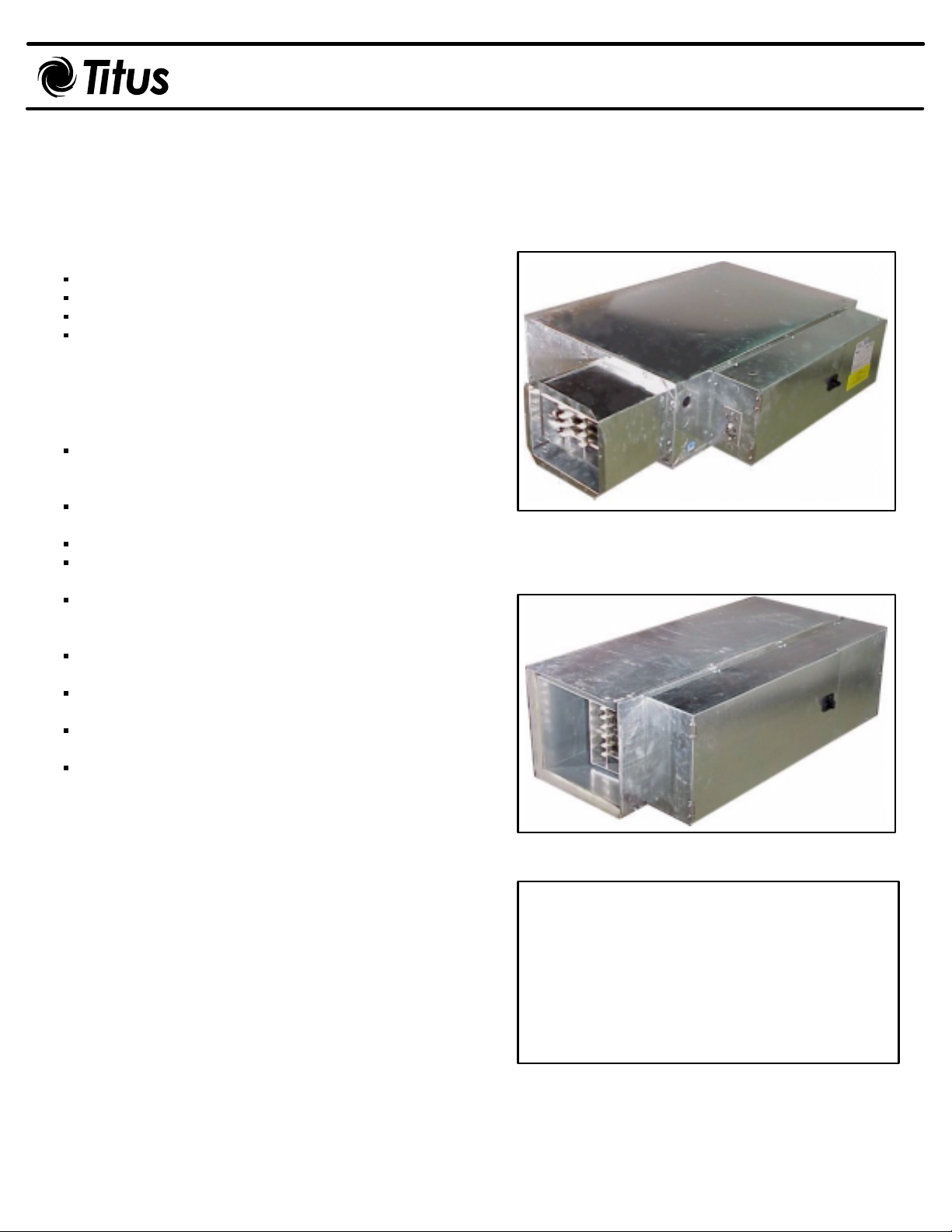
Fan Terminal Unit with Heater
Single Duct Terminal Unit with Heater
CAUTION
ELECTRIC SHOCK MAY RESULT
1. DISCONNECT POWER BEFORE
SERVICING UNIT.
2. DO NOT OPERATE UNIT WITHOUT
CONTROL COVER INSTALLED.
EHeat-IOM-2.0 6-1-01
Data Label
All electric coils are provided with a product label affixed to the control enclosure cover. This label contains all
necessary information regarding electrical power and circuit protection requirements, as specified by UL. See Figure 1.
Figure 1.
FAN UNIT
MODEL NO DTQ S CODE 99-361901-B 6 REV:
MOTOR VOLT 277 PHASE 1 HZ 60
HP 1/6 FLA(EA) 1.40
HEAT VOLT 277 PHAS E 1 HZ 60
KW 6.0 AMPS 21.66
MOTOR(S) ARE THERMALLY PROTECTED MAXIMUM OVERCURRENT
N. SUPPLY CIRCUIT AMPS 1.38 AMP PROTECTION = 15 AMP
MI
XXXXXXXXXXXXXXXXXXXXXXXXXXX
MAX. OUTLET AIR TEMPERATURE 200
UNIT DESIGNED TO OPERATE AT NO LESS THAN 0.2 IWG STATIC PRESSURE
ZERO CLEARANCE FROM UNIT, CONNECTED DUCT AND/OR PLENUM
TO COMBUSTIBLE MATERIAL.
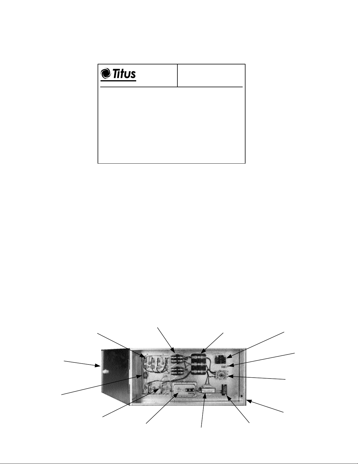
Heater Control Enclosure
O
F
Figure 2 shows the interior of a typical electric coil control enclosure. Various components contained within this
enclosure are necessary for the safe operation of the product. An interlocking safety door disconnect switch is
recommended, but not required. It prevents access to the enclosure until all ungrounded conductors are disconnected
from the electric coil circuit. If an optional disconnect switch is not ordered, a terminal block will be provided for single
point electrical hook-up. A ground lug is provided to insure proper grounding of the terminal unit housing and
enclosure. Optional line fuses and fan motor fuses provide overcurrent protection, if permitted by local building
codes. An air flow switch is always provided to lock-out the coil when there is no air flow across the elements. An
automatic reset thermal cut-out is required to de-energize elements whenever discharge temperature is excessive.
The coil will resume operation when discharge temperatures decrease. An optional manual reset thermal cut-out will
protect the elements in the event of a thermal cut-out failure and prevent the coil from operating until qualified service
personnel can make repairs. Fuse links are required on all single duct electric coils to provide safety in event of a
thermal cut-out failure. Fuse links must be replaced as they cannot be reset. A control transformer is provided
whenever a 24 V circuit is required. PE switches may be load bearing on small pneumatically-controlled electric coil s,
or pilot duty when current loads require magnetic contactors. Optional mercury contactors are available for extra
long service life and / or silent operation. In addition to these components, fan powered terminals may include an SCR
motor speed control and a fan relay.
Heating Element Terminal Box
Recessed into Air Stream for
Accurate Temperature Sensing by
Thermal Cutouts
Hinged Access Door
Latched by Optional
Interlock Disconnect Switch
Automatic Reset
Thermal Cutout
Magnetic Contactors
for Primary Control
Line Fuse Block and
Fuses (3 Phase
Shown)
Fan Interlock Relay
Ground Lug
Door Interlock
Disconnect Switch
(Optional)
Figure 2.
Heating Elements
Staggered for Uniform
Heat Transfer
Differential Pressure
Air Flow Switch
Control Transformer
NEMA 1 Casing, Heavy
Gauge Corrosion
Resistant Steel
Control Circuit
Terminal Block
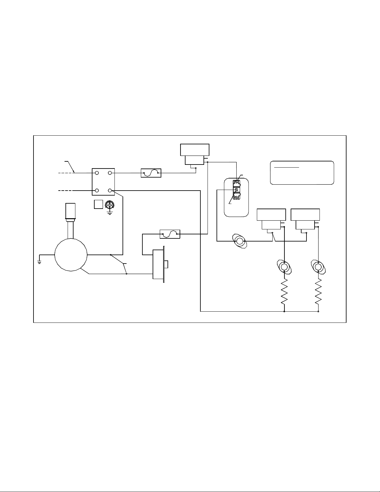
Wiring Diagrams
Figure 3 - Typical pneumatic parallel fan powered terminal with load bearing PE switches.
Figure 4 - Typical pneumatic parallel fan powered terminal with contactors.
Figure 5 - Typical pneumatic series fan powered terminal with load bearing PE switches.
Figure 6 - Typical fan powered terminal with factory wired controls.
Figure 7 - Typical electronic fan powered terminal with field mounted controls.
Figure 8 - Typical electronic single duct terminal with field mounted controls.
Figure 9 - Typical pneumatic single duct terminal with contactor.
Figure 3.
Pneumatic Parallel (Variable Volume) Fan Powered Terminal
Electric Reheat, 277V, 1φ, 2 Stage, 2 Element
P.E. SWITCH
FAN
USE COPPER
CONDUCTORS ONLY
L1
N
BLACK
WHITE
TERM BLOCK
OR OPTIONAL
DISC SWITCH
BROWN
WHITE
OPTIONAL
LINE FUSE
BLACK
COM
NC
ORANGE
NO
COM
BLACK
EHeat-IOM-3.0 6-1-01
CAUTION:
ELECTRIC SHOCK MAY RESULT
DISCONNECT POWER SUPPLY
PRIOR TO SERVICING UNIT.
GREEN
MOTOR
ORANGE
N.O.
AFS
OPTIONAL
MANUAL RESET
ORANGE
SEE NOTE #1
P.E. SWITCH
STEP 1
COM
WHITE
SEE NOTE #1
P.E. SWITCH
STEP 2
NC
NO
ORANGE
BROWN
COM
NC
NO
RED
THERMAL
HI LIMIT
(TYP)
CAP
BROWN
BROWN
3
G
WHITE
1
BLACK
NOTES:
1. FACTORY WIRED P.E. SWITCH. DIRECT ACTING WIRED N.C.,
REVERSE ACTING WIRED N.O. AND PIPED TO THERMOSTAT LINE.
WHITE
OPTIONAL
CRIMP CAP
RED
MOTOR FUSE
RED
RED
SCR
BLACK
 Loading...