

Page 1
INSTALLATION &
OPERATION MANUAL
Displacement
Ventilation Diffusers
DVCP / DVVC / DVHC
DVBC / DVRI / DVIR
Redefine your comfort zone. ™ | www.titus-hvac.com
Page 2

IOM
DVCP / DVVC / DVHC
DVBC / DVRI / DVIR
Table of Contents
Section 1 DVCP (Round Diffuser)
Diffuser Installation & Commissioning ............................................................................................... 3
Duct Cover Installation ......................................................................................................................... 4
Section 2 DVVC (Radius Corner Diffuser)
Diffuser Installation & Commissioning ................................................................................................ 8
Duct Cover Installation ......................................................................................................................... 9
Section 3 DVHC (Semi-Round Diffuser)
Diffuser Installation & Commissioning .............................................................................................. 12
Duct Cover Installation ....................................................................................................................... 13
Section 4 DVBC (Rectangular Diffuser)
Diffuser Installation & Commissioning .............................................................................................. 16
Duct Cover Installation ....................................................................................................................... 17
Section 5 DVRI (Rectangular Diffuser)
Diffuser Installation & Commissioning .............................................................................................. 20
Section 6 DVIR (Rectangular Diffuser)
Diffuser Installation & Commissioning .............................................................................................. 23
2
Installation Manual-DISPLACEMENT VENTILATION DIFFUSERS
Redefine your comfort zone. ™ | www.titus-hvac.com
Page 3
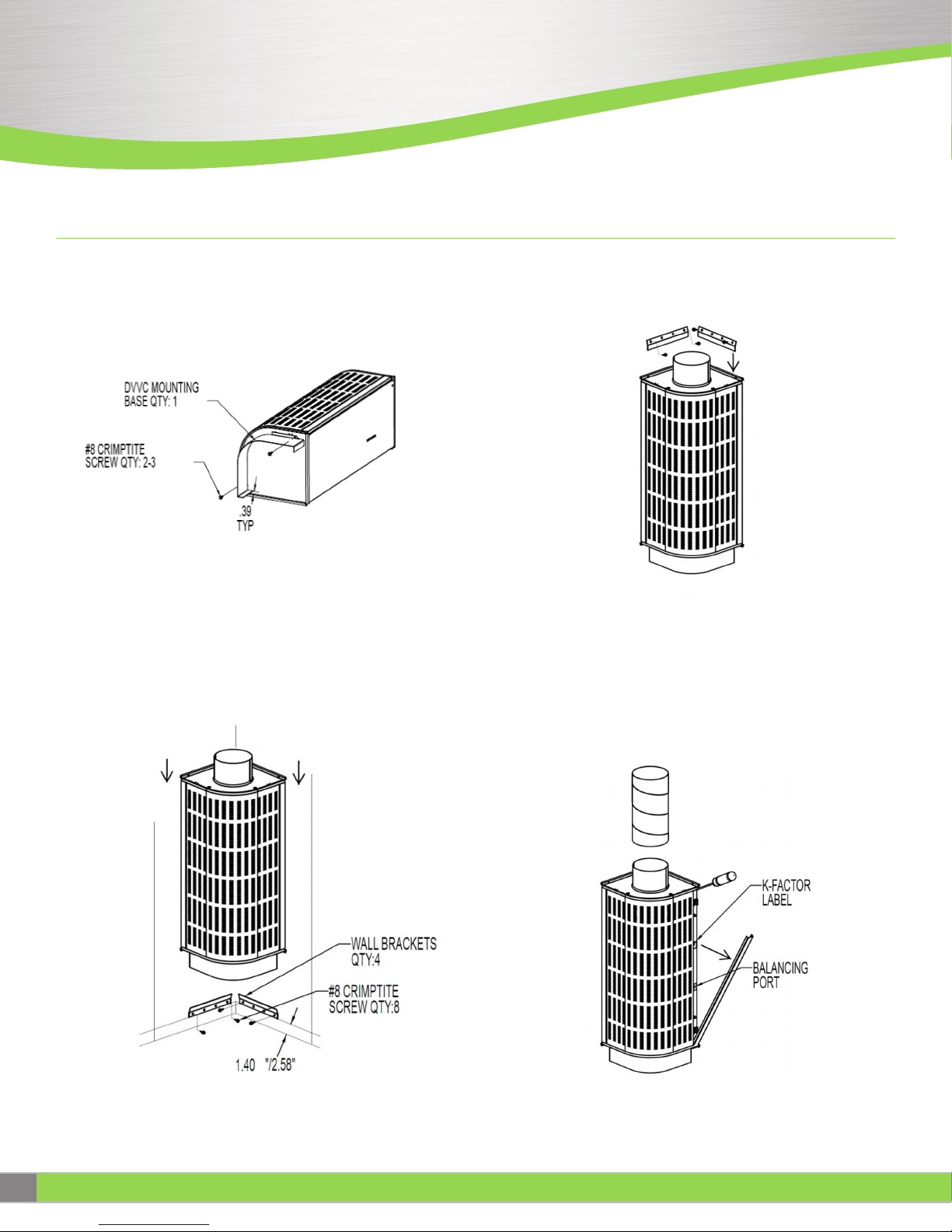
DVCP Installation
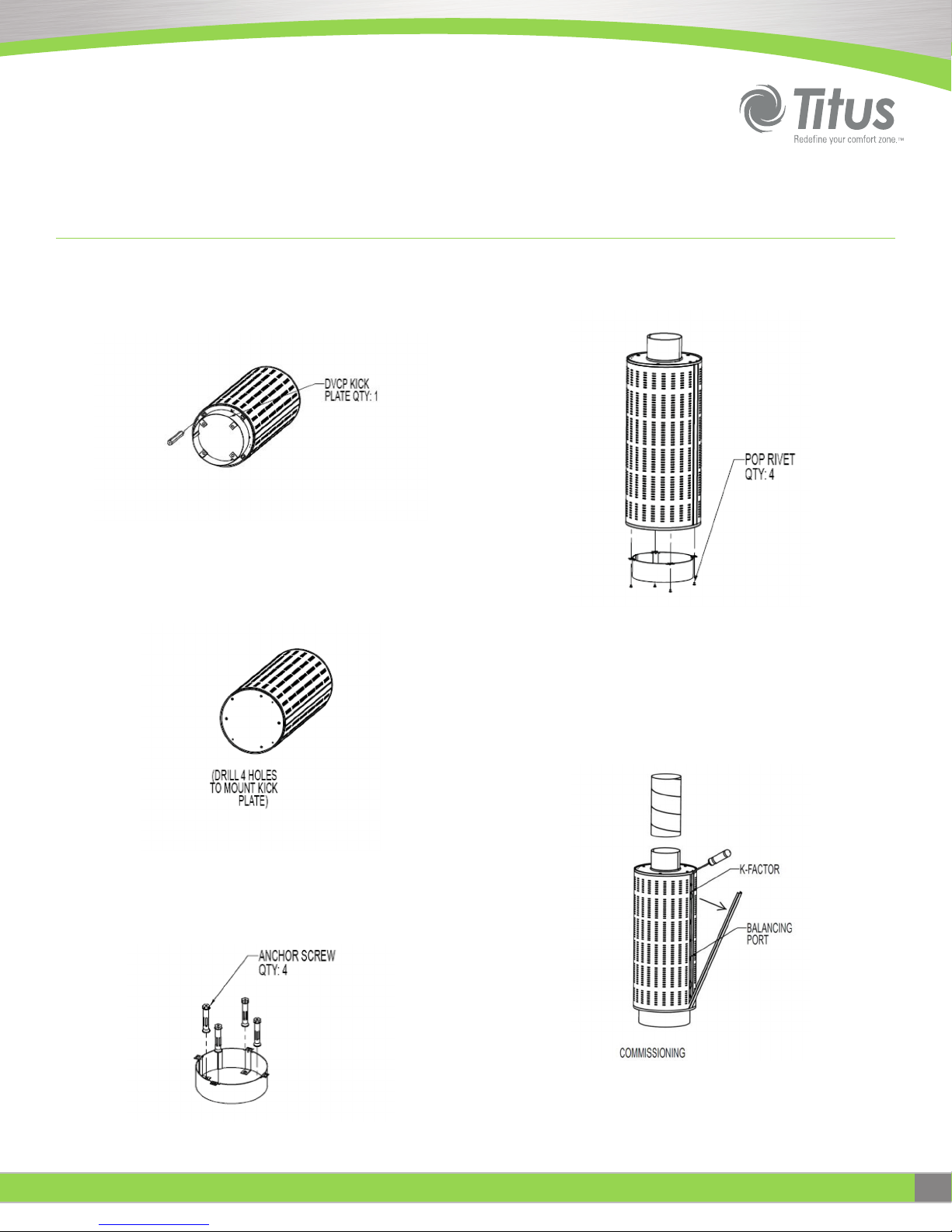
STEP 1
Mark the positions to drill the 4 holes on the bottom plate of the unit.
Figure 1
STEP 2
Drill holes to mount the mounting base.
STEP 4
Install the unit onto the mounting base using pop rivets.
Figure 4
Commissioning (Balancing): The balancing port is positioned on the side
behind the decor strip. The K-factor of the unit is stated on the K-factor
label mounted on one of the side of the balancing port. The k-factor can
also be found on our website in the relevant k-factor guide. See Figure 5
Figure 2
STEP 3
Install mounting base to the floor using anchor screws.
Figure 3
Redefine your comfort zone. ™ | www.titus-hvac.com
Figure 5
Installation Manual-DISPLACEMENT VENTILATION DIFFUSERS
3
Page 4
IOM
DVCP / DVVC / DVHC
DVBC / DVRI / DVIR
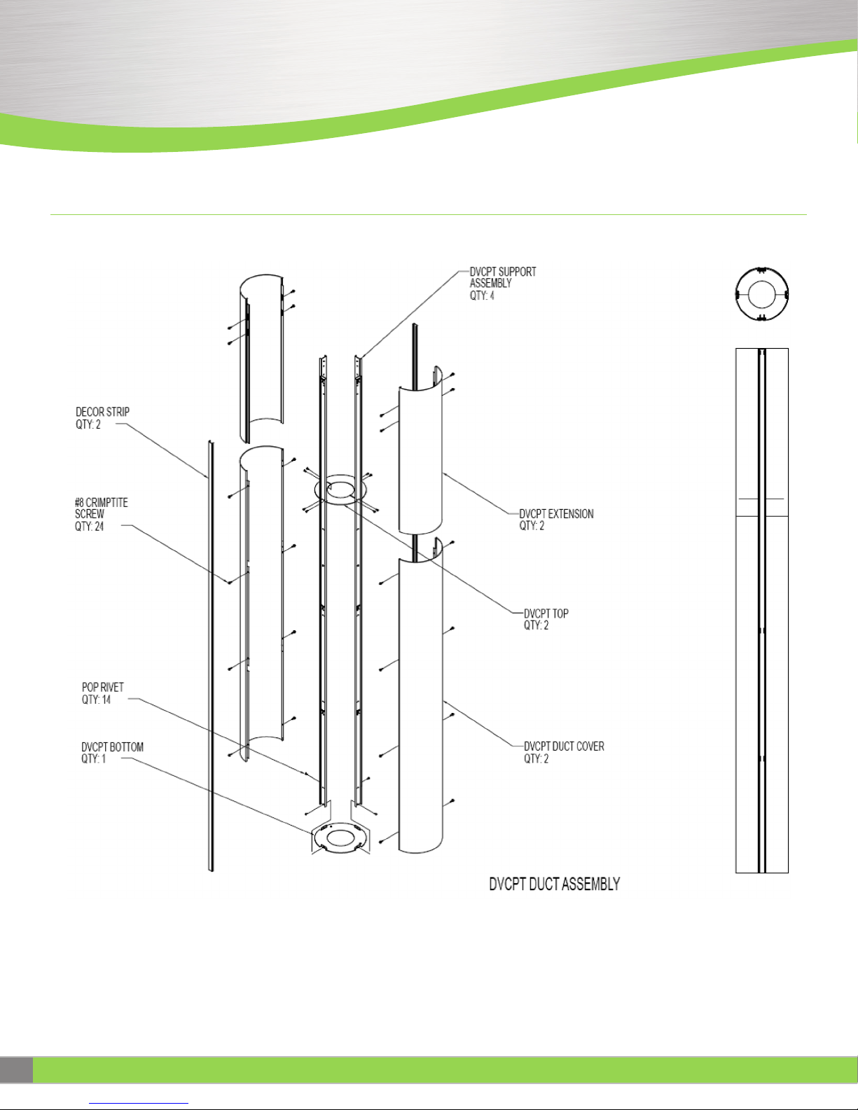
DVCP Duct Cover Installation
4
Installation Manual-DISPLACEMENT VENTILATION DIFFUSERS
Redefine your comfort zone. ™ | www.titus-hvac.com
Page 5
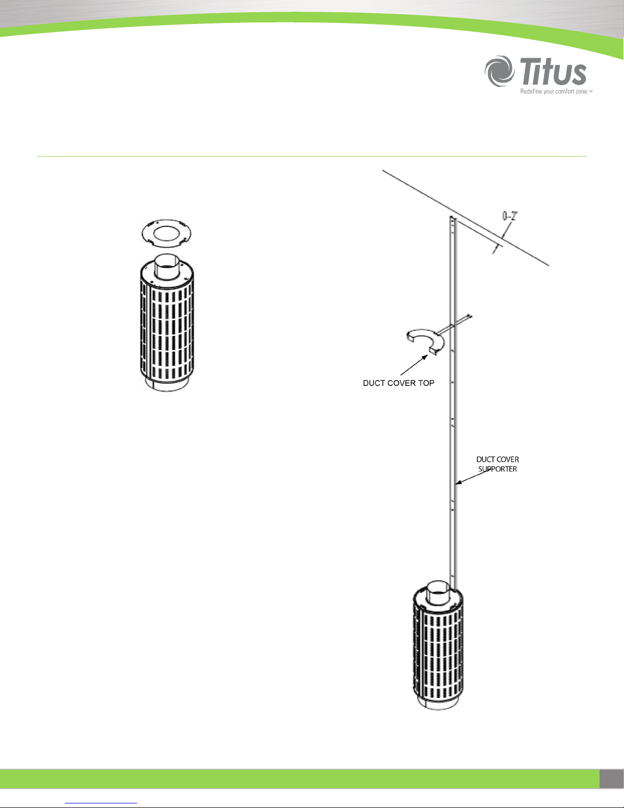
DVCP Duct Cover Installation (continued)
STEP 1
Mount the duct cover bottom on the top of the unit.
Figure 1
STEP 2
Mount the duct cover support assembly on the top of the unit. Align the
holes on the flange of the duct cover bottom and the duct cover support
assembly and cut the support according to the ceiling height keeping
2” distance between the ceiling and the top of the duct covert support
assembly. Align the duct cover top with the three holes on the support
assembly and rivet the duct cover top with the duct cover support assembly
in 2 places.
Figure 2
Redefine your comfort zone. ™ | www.titus-hvac.com
Installation Manual-DISPLACEMENT VENTILATION DIFFUSERS
5
Page 6
IOM
DVCP / DVVC / DVHC
DVBC / DVRI / DVIR
DVCP Duct Cover Installation (continued)
STEP 3
Install the duct onto the unit. Install the second duct cover top to the duct
cover support assembly enclosing the duct. Assemble both the duct cover
top together using pop rivets.
STEP 4
Assemble all four duct cover support assemblies to the duct cover bottom
using pop rivets.
Figure 3 Figure 4
6
Installation Manual-DISPLACEMENT VENTILATION DIFFUSERS
Redefine your comfort zone. ™ | www.titus-hvac.com
Page 7
DVCP Duct Cover Installation (continued)
STEP 5
Align the top edge of the duct cover support assembly with the top face
of the extension and install the extension assembly onto the duct cover
support assembly using screws. (Décor strip of the unit should align with
the décor strip of the duct cover assembly)
STEP 6
Place the duct cover on the top of the unit and assemble it to the duct
cover support assembly using screws. Snap the décor strips into the
springs of the duct cover support assemblies.
Figure 5 Figure 6
Redefine your comfort zone. ™ | www.titus-hvac.com
Installation Manual-DISPLACEMENT VENTILATION DIFFUSERS
7
Page 8
IOM
DVCP / DVVC / DVHC
DVBC / DVRI / DVIR
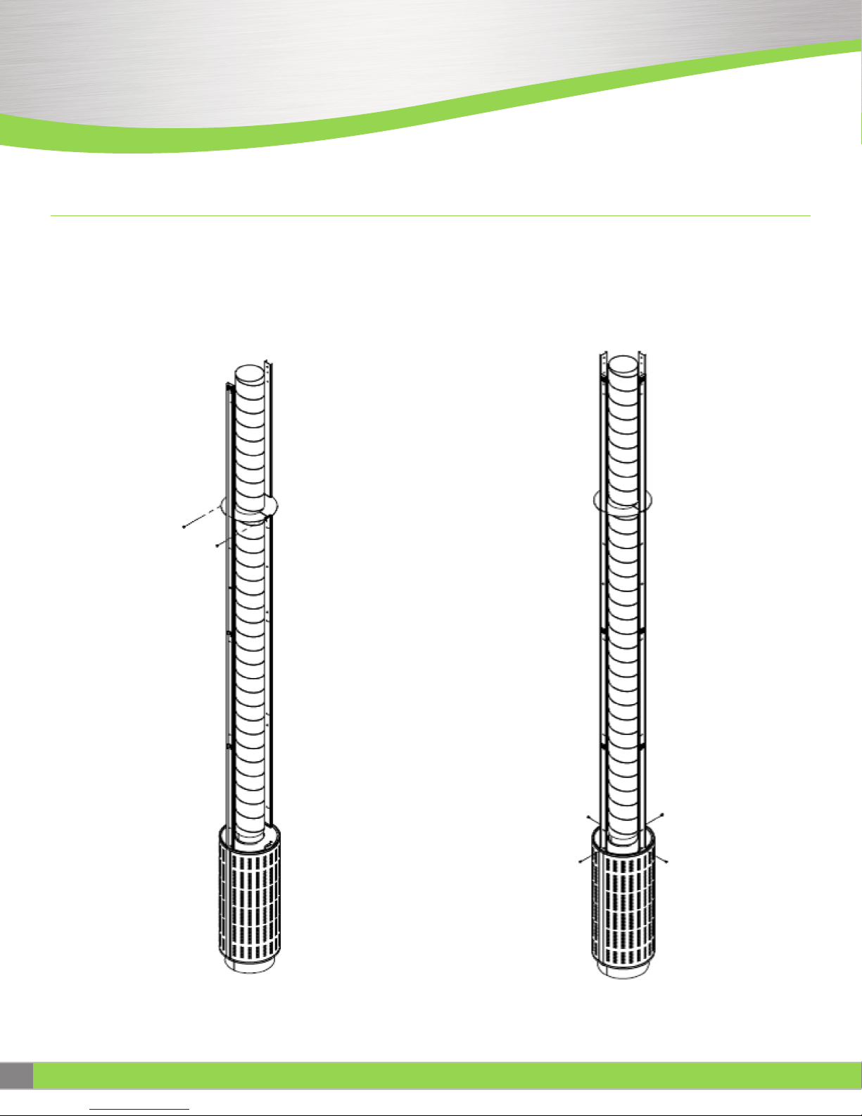
DVVC Installation
STEP 1
Drill the holes on the bottom plate of the unit and the mounting base.
Install the mounting base into place using screws.
Figure 1
STEP 2
Install wall brackets to the wall using screws and slide the bottom of the
unit into the angle wall brackets.
STEP 3
Install wall bracket to the wall to hold the top of the unit using screws.
Figure 3
Commissioning (Balancing): The balancing port is positioned on the side
behind the decor strip. The K-factor of the unit is stated on the K-factor
label mounted on one of the side of the balancing port. The k-factor can
also be found on our website in the relevant k-factor guide. See Figure 4
Figure 2
8
Installation Manual-DISPLACEMENT VENTILATION DIFFUSERS
Figure 4
Redefine your comfort zone. ™ | www.titus-hvac.com
Page 9

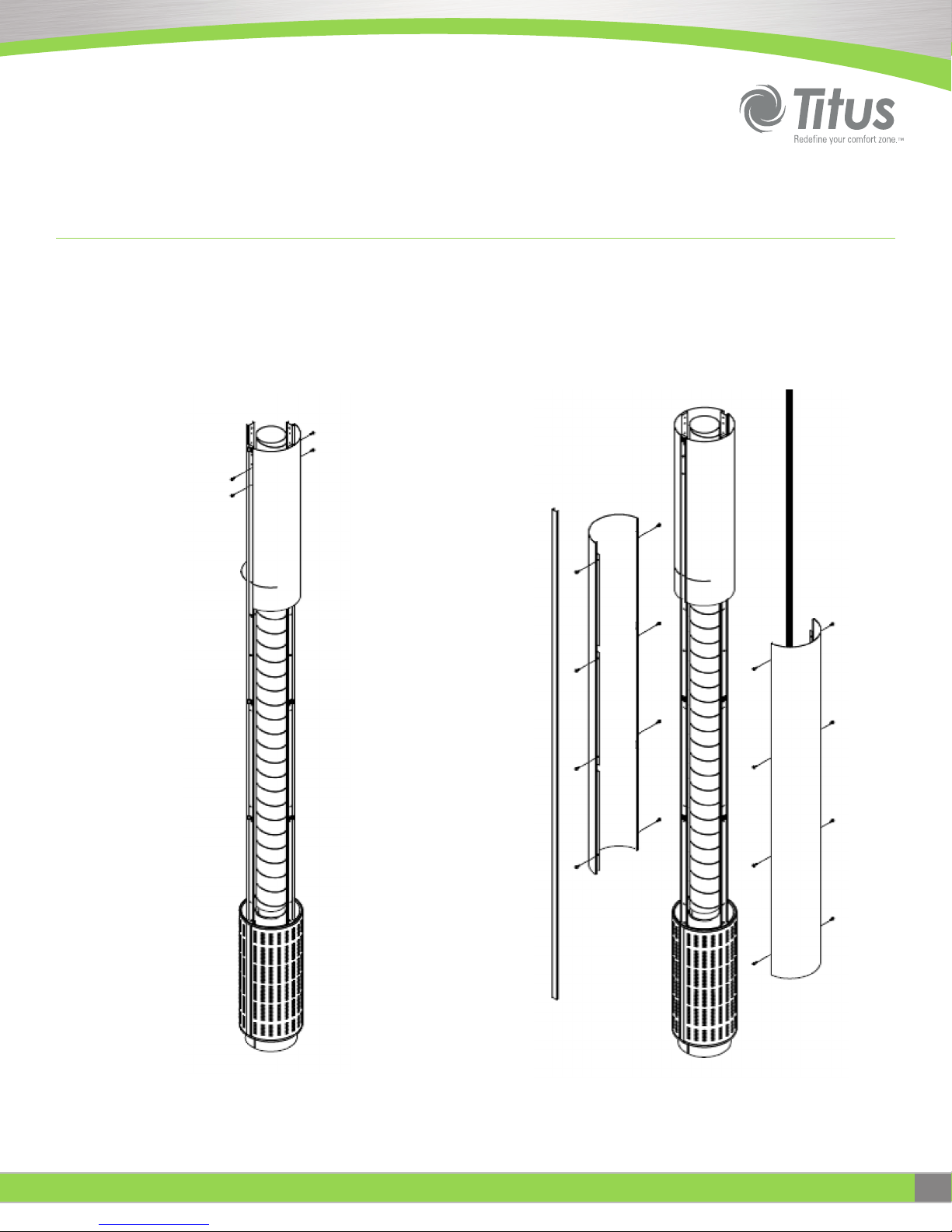
DVVC Duct Cover Installation
Redefine your comfort zone. ™ | www.titus-hvac.com
Installation Manual-DISPLACEMENT VENTILATION DIFFUSERS
9
Page 10

IOM
DVCP / DVVC / DVHC
DVBC / DVRI / DVIR
DVVC Duct Cover Installation (continued)
STEP 1
Cut the brackets according to the ceiling height keeping 0-2” distance
between the ceiling and top of the bracket.
STEP 2
Using spacers align the brackets to the end of the unit keeping 0.67”
distance from the end face of the unit. Screw the left and right brackets
to the wall.
Figure 1
10
Installation Manual-DISPLACEMENT VENTILATION DIFFUSERS
Figure 2
Redefine your comfort zone. ™ | www.titus-hvac.com
Page 11

DVVC Duct Cover Installation (continued)
STEP 3
Install the duct onto the unit. Align the top edge of the brackets with the
top face of the extension and install the extension assembly onto the
brackets using screws.
STEP 4
Place the duct cover assembly on the top of the unit and assemble it to
the brackets using screws. Snap the décor strips into the springs of the
extension and duct cover assemblies.
Figure 3 Figure 4
Redefine your comfort zone. ™ | www.titus-hvac.com
Installation Manual-DISPLACEMENT VENTILATION DIFFUSERS
11
Page 12

IOM
DVCP / DVVC / DVHC
DVBC / DVRI / DVIR
DVHC Installation
STEP 1
Drill the holes on the bottom plate of the unit and the mounting base.
Install the mounting base into place using screws.
Figure 1
STEP 2
Install wall bracket to the wall using screws and slide the bottom of the
unit into the angle wall bracket.
STEP 3
Install wall bracket to the wall to hold the top of the unit using screws.
Figure 3
Commissioning (Balancing): The balancing port is positioned on the side
behind the decor strip. The K-factor of the unit is stated on the K-factor
label mounted on one of the side of the balancing port. The k-factor can
also be found on our website in the relevant k-factor guide. See Figure 4
Figure 2
12
Installation Manual-DISPLACEMENT VENTILATION DIFFUSERS
Figure 4
Redefine your comfort zone. ™ | www.titus-hvac.com
Page 13

DVHC Duct Cover Installation
Redefine your comfort zone. ™ | www.titus-hvac.com
Installation Manual-DISPLACEMENT VENTILATION DIFFUSERS
13
Page 14

IOM
DVCP / DVVC / DVHC
DVBC / DVRI / DVIR
DVHC Duct Cover Installation (continued)
STEP 1
Cut the brackets according to the ceiling height keeping 0-2” distance
between the ceiling and top of the bracket.
STEP 2
Using spacers align the brackets to the end of the unit keeping 0.67”
distance from the end face of the unit. Screw the left and right brackets
to the wall.
Figure 1
14
Installation Manual-DISPLACEMENT VENTILATION DIFFUSERS
Figure 2
Redefine your comfort zone. ™ | www.titus-hvac.com
Page 15

DVHC Duct Cover Installation (continued)
STEP 3
Install the duct onto the unit. Align the top edge of the brackets with the
top face of the extension and install the extension assembly onto the
brackets using screws.
STEP 4
Place the duct cover assembly on the top of the unit and assemble it to
the brackets using screws. Snap the décor strips into the springs of the
extension and duct cover assemblies.
Figure 3
Redefine your comfort zone. ™ | www.titus-hvac.com
Figure 4
Installation Manual-DISPLACEMENT VENTILATION DIFFUSERS
15
Page 16

IOM
DVCP / DVVC / DVHC
DVBC / DVRI / DVIR
DVBC Installation
STEP 1
Drill the holes on the bottom plate of the unit and the mounting base.
Install the mounting base into place using screws.
Figure 1
STEP 2
Install wall bracket to the wall using screws and slide the bottom of the
unit into the angle wall bracket.
STEP 3
Install wall bracket to the wall to hold the top of the unit using screws.
Figure 3
Commissioning (Balancing): The balancing port is positioned on the side
behind the decor strip. The K-factor of the unit is stated on the K-factor
label mounted on one of the side of the balancing port. The k-factor can
also be found on our website in the relevant k-factor guide. See Figure 4
Figure 2
16
Installation Manual-DISPLACEMENT VENTILATION DIFFUSERS
Figure 4
Redefine your comfort zone. ™ | www.titus-hvac.com
Page 17

DVBC Duct Cover Installation
Redefine your comfort zone. ™ | www.titus-hvac.com
Installation Manual-DISPLACEMENT VENTILATION DIFFUSERS
17
Page 18

IOM
DVCP / DVVC / DVHC
DVBC / DVRI / DVIR
DVBC Duct Cover Installation (continued)
STEP 1
Cut the brackets according to the ceiling height keeping 0-2” distance
between the ceiling and top of the bracket.
STEP 2
Using spacers align the brackets to the end of the unit keeping 0.67”
distance from the end face of the unit. Screw the left and right brackets
to the wall.
Figure 2
Figure 1
STEP 3
Install the duct onto the unit. Align the top edge of the brackets with the
top face of the extension and install the extension assembly onto the
brackets using screws.
Figure 3
18
Installation Manual-DISPLACEMENT VENTILATION DIFFUSERS
Redefine your comfort zone. ™ | www.titus-hvac.com
Page 19

DVBC Duct Cover Installation (continued)
STEP 4
Mount the mounting fixture assembly on the top of the unit.
STEP 5
Slide the duct cover in-between the mounting strip and the aluminum strip
and assemble it to the brackets using screws. Snap the décor strips into
the springs of the extension and duct cover assemblies.
Figure 4
Redefine your comfort zone. ™ | www.titus-hvac.com
Figure 5
Installation Manual-DISPLACEMENT VENTILATION DIFFUSERS
19
Page 20

IOM
DVCP / DVVC / DVHC
DVBC / DVRI / DVIR
DVRI Installation
STEP 1
Drill the holes and install the mounting base into place using screws.
Figure 1
STEP 2
In Wall Mounting - Install the four Angle brackets on the top of the unit
using screws. (You may need to cut the angle strips to match the overall
dimensions of the unit.) Install the unit into the wooden frame and screw
to the sides. Install angle strips from the sides to the front of the unit
using screws.
20
Installation Manual-DISPLACEMENT VENTILATION DIFFUSERS
Figure 2
Redefine your comfort zone. ™ | www.titus-hvac.com
Page 21

DVRI Installation (continued)
STEP 3
Floor Mounting - Using Angle Strips screw the unit to the wall from the top
and the sides. (You may need to cut the angle strips to match the overall
dimensions of the unit.)
STEP 4
Mounting against the wall - Using Angle Strips screw the unit against the
wall from the top and the bottom. (You may need to cut the angle strips to
match the overall dimensions of the unit.)
Figure 3
Redefine your comfort zone. ™ | www.titus-hvac.com
Figure 4
Installation Manual-DISPLACEMENT VENTILATION DIFFUSERS
21
Page 22

IOM
DVCP / DVVC / DVHC
DVBC / DVRI / DVIR
DVRI Installation (continued)
Commissioning (Balancing): Uninstall the front cover for maintenance.
For Size < 10 the balancing port is positioned on the side of the unit behind
the white plug and For Size > 12 the balancing port is positioned in the
center behind the decor strip. The K-factor of the unit is stated on K-factor
label mounted on long bracket behind the front cover for Size < 10 and on
one of the side of the balancing port for Size > 12. The k-factor can also be
found on our website in the relevant k-factor guide. See Figure 6
Figure 5
Figure 6
22
Installation Manual-DISPLACEMENT VENTILATION DIFFUSERS
Redefine your comfort zone. ™ | www.titus-hvac.com
Page 23

DVIR Installation
STEP 1
Screw the Plenum-Inlet Assembly into place through the sides.
Note: Plenum-Inlet Assembly is mounted before the wall board is fixed
STEP 3
Install front cover onto the Mounting frame-Distributor assembly.
Figure 3
Commissioning (Balancing): Uninstall the front cover for commissioning.
The balancing port is positioned on the lower edge of the unit. The K-factor
of the unit is stated on K-factor label placed on one of the side of the
Plenum box. The k-factor can also be found on our website in the relevant
k-factor guide. See Figure 4
Figure 1
STEP 2
Install the Mounting frame-Distributor assembly to the wall board
using screws.
Figure 2
Redefine your comfort zone. ™ | www.titus-hvac.com
Figure 4
Installation Manual-DISPLACEMENT VENTILATION DIFFUSERS
23
Page 24

605 Shiloh Rd
Plano TX 75074
ofc: 972.212.4800
fax: 972.212.4884
Redefine your comfort zone. ™ | www.titus-hvac.com
 Loading...