

Titan Tool Speedflo PowrTwin 8900XLT Owner's Manual
Owner’s Manual
For professional use only
Do not use this equipment
before reading this manual!
PowrTwin 8900XLT
Model Number:
305
-
Gas Bare
DC Electric Bare 449-310
Gas Complete 449-315
Gas/Electric C
Printed in the U. S.
A.
omplet
449
-320
449
e
NOTE: This manual contains important warnings
and instructions. Please read and retain for
reference.
0205 © 2005 Titan Tool Inc. All rights reserved. Form No. 313-2486A
Table of Contents
CAUTION
WARNING
WARNING
afety Precautions. . . . . . . . . . . . . . . . . . . . . . . . . . . . . . . . . 2
S
rounding Instructions . . . . . . . . . . . . . . . . . . . . . . . . . . . . . 3
G
asoline Engine Safety . . . . . . . . . . . . . . . . . . . . . . . . . . . . 4
G
pecifications. . . . . . . . . . . . . . . . . . . . . . . . . . . . . . . . . . . . . 4
S
ntroduction . . . . . . . . . . . . . . . . . . . . . . . . . . . . . . . . . . . . . . 5
I
peration . . . . . . . . . . . . . . . . . . . . . . . . . . . . . . . . . . . . . . . . 5
O
ueling . . . . . . . . . . . . . . . . . . . . . . . . . . . . . . . . . . . . . . . . . 5
F
etup . . . . . . . . . . . . . . . . . . . . . . . . . . . . . . . . . . . . . . . . . . 6
S
reparing to Paint. . . . . . . . . . . . . . . . . . . . . . . . . . . . . . . . . 7
P
ainting. . . . . . . . . . . . . . . . . . . . . . . . . . . . . . . . . . . . . . . . . 8
P
ressure Relief Procedure . . . . . . . . . . . . . . . . . . . . . . . . . . 9
P
leanup . . . . . . . . . . . . . . . . . . . . . . . . . . . . . . . . . . . . . . . . . . 9
C
leaning a Clogged Tip . . . . . . . . . . . . . . . . . . . . . . . . . . . 10
C
aintenance . . . . . . . . . . . . . . . . . . . . . . . . . . . . . . . . . . . . . 10
M
aily Maintenance . . . . . . . . . . . . . . . . . . . . . . . . . . . . . . . 10
D
aintaining the Filter Assembly . . . . . . . . . . . . . . . . . . . . . 10
M
aintaining the Hydraulic System . . . . . . . . . . . . . . . . . . . 11
M
aintaining the Fluid Section . . . . . . . . . . . . . . . . . . . . . . . 11
M
Basic Engine Maintenance (gas engine) . . . . . . . . . . . . . . 11
Replacing the Motor Brushes (electric motor) . . . . . . . . . . 12
Troubleshooting. . . . . . . . . . . . . . . . . . . . . . . . . . . . . . . . . . 13
Airless Gun . . . . . . . . . . . . . . . . . . . . . . . . . . . . . . . . . . . . . 13
Fluid Section. . . . . . . . . . . . . . . . . . . . . . . . . . . . . . . . . . . . 13
Hydraulic Motor . . . . . . . . . . . . . . . . . . . . . . . . . . . . . . . . . 14
Spray Patterns . . . . . . . . . . . . . . . . . . . . . . . . . . . . . . . . . . 15
Parts Lists and Service Instructions . . . . . . . . . . . . . . . . . 16
Main Assembly . . . . . . . . . . . . . . . . . . . . . . . . . . . . . . . . . . 16
Bleed Hose Assembly with Valve . . . . . . . . . . . . . . . . . . . . 16
Cart Assembly . . . . . . . . . . . . . . . . . . . . . . . . . . . . . . . . . . 17
Belt Guard Assembly . . . . . . . . . . . . . . . . . . . . . . . . . . . . . 17
Hydraulic System . . . . . . . . . . . . . . . . . . . . . . . . . . . . . . . . 18
DC— Electric Convertokit. . . . . . . . . . . . . . . . . . . . . . . . . . 19
Gas Convertokit . . . . . . . . . . . . . . . . . . . . . . . . . . . . . . . . . 20
Filter Assembly . . . . . . . . . . . . . . . . . . . . . . . . . . . . . . . . . . 20
Bleed Valve Assembly . . . . . . . . . . . . . . . . . . . . . . . . . . . . 21
Siphon Hose Assembly . . . . . . . . . . . . . . . . . . . . . . . . . . . 21
Hydraulic Motor . . . . . . . . . . . . . . . . . . . . . . . . . . . . . . . . . 22
Fluid Section. . . . . . . . . . . . . . . . . . . . . . . . . . . . . . . . . . . . 24
Gun Manifold Assemblies (optional). . . . . . . . . . . . . . . . . . 26
SAE O-Ring Fitting Installation. . . . . . . . . . . . . . . . . . . . . . 27
Accessories and Service Kits. . . . . . . . . . . . . . . . . . . . . . . 27
Airless Tip Selection. . . . . . . . . . . . . . . . . . . . . . . . . . . . . . 27
Limited Warranty . . . . . . . . . . . . . . . . . . . . . . . . . . . . . . . . . 32
Safety Precautions
This manual contains information that must be read and
understood before using the equipment. When you come to
an area that has one of the following symbols, pay particular
attention and make certain to heed the safeguard.
HAZARD: Injection injury - A high pressure stream
O NOT TREAT AN INJECTION INJURY AS A SIMPLE
D
UT! Injection can lead to amputation. See a physician
C
mmediately.
i
The maximum operating range of the gun is 3300 PSI /
22.8 MPa fluid pressure.
PREVENTION:
•
• NEVER allow any part of the body to touch the fluid stream.
• NEVER put your hand in front of the gun. Gloves will not
• ALWAYS lock the gun trigger, shut the pump off, and
• ALWAYS keep the tip guard in place while spraying. The
• ALWAYS remove the spray tip before flushing or cleaning
• The paint hose can develop leaks from wear, kinking and
• NEVER use a spray gun without a trigger lock and trigger
• All accessories must be rated at or above the maximum
NOTE TO PHYSICIAN:
Injection into the skin is a traumatic injury. It is
important to treat the injury as soon as possible. DO
NOT delay treatment to research toxicity. Toxicity is a
concern with some coatings injected directly into the
blood stream. Consultation with a plastic surgeon or
reconstructive hand surgeon may be advisable.
produced by this equipment can pierce the
skin and underlying tissues, leading to serious
injury and possible amputation. See a
physician immediately.
NEVER aim the gun at any part of the body.
DO NOT allow body to touch a leak in the fluid hose.
provide protection against an injection injury.
release all pressure before servicing, cleaning the tip or
guard, changing tip, or leaving unattended. Pressure will
not be released by turning off the motor. The
PRIME/SPRAY valve or pressure bleed valve must be
turned to their appropriate positions to relieve system
pressure. Refer to the PRESSURE RELIEF
PROCEDURE described in this manual.
tip guard provides some protection but is mainly a
warning device.
the system.
abuse. A leak can inject material into the skin. Inspect
the hose before each use.
guard in place and in good working order.
operating pressure range of the airless sprayer. This
includes spray tips, guns, extensions, and hose.
This symbol indicates a potential hazard that may cause
serious injury or loss of life. Important safety information
will follow.
This symbol indicates a potential hazard to you or to the
equipment. Important information that tells how to
prevent damage to the equipment or how to avoid causes
of minor injuries will follow.
NOTE: Notes give important information that should
be given special attention.
English
HAZARD: EXPLOSION OR FIRE - Solvent and paint fumes
can explode or ignite. Severe injury and/or
property damage can occur.
PREVENTION:
• Provide extensive exhaust and fresh air introduction to
keep the air within the spray area free from accumulation
of flammable vapors.
• Avoid all ignition sources such as static electric sparks,
open flames, pilot lights, and hot objects. Connecting or
disconnecting power cords or working light switches can
make sparks.
• Do not smoke in spray area.
• Fire extinguisher must be present and in good working
order.
• Place paint pump in a well ventilated area. Flammable
vapors are often heavier than air. Floor area must be
extremely well ventilated. The paint pump contains arcing
parts that emit spark and can ignite vapors.
• The equipment and objects in and around the spray area
must be properly grounded to prevent static sparks.
• Use only conductive or grounded high pressure fluid hose.
Gun must be grounded through hose connections.
2 © Titan Tool Inc. All rights reserved.
• Power cord must be connected to a grounded circuit
CAUTION
(electric models only).
Always flush unit into a separate metal container, at low
•
ump pressure, with spray tip removed. Hold gun firmly
p
gainst side of container to ground container and prevent
a
tatic sparks.
s
• Follow the material and solvent manufacturer's warnings
and instructions.
• Use extreme caution when using materials with a
flashpoint below 70° F (21° C). Flashpoint is the
temperature that a fluid can produce enough vapors to
ignite.
• Plastic can cause static sparks. Never hang plastic to
enclose a spray area. Do not use plastic drop cloths
when spraying flammable materials.
• Use lowest possible pressure to flush equipment.
GAS ENGINE (WHERE APPLICABLE)
lways place pump outside of structure in fresh air. Keep all
A
solvents away from the engine exhaust. Never fill fuel tank
with a running or hot engine. Hot surface can ignite spilled
fuel. Always attach ground wire from pump unit to a grounded
object, such as a metal water pipe. Refer to engine owner’s
manual for complete safety information.
HAZARD: EXPLOSION HAZARD DUE TO INCOMPATIBLE
PREVENTION:
• Do not use materials containing bleach or chlorine.
• Do not use halogenated hydrocarbon solvents such as
• Contact your coating supplier about the compatibility of
HAZARD: HAZARDOUS VAPORS - Paints, solvents,
PREVENTION:
• Use a respirator or mask if vapors can be inhaled. Read
• Wear protective eyewear.
• Wear protective clothing as required by coating
HAZARD:
PREVENTION:
• Read all instructions and safety precautions before
• Always disconnect the motor from the power supply
•
• The United States Government Safety Standards have
•
• Before each use, check all hoses for cuts, leaks,
MATERIALS - Will cause severe injury or
property damage.
mildewcide, methylene chloride and 1,1,1 trichloroethane. They are not compatible with aluminum.
material with aluminum.
insecticides, and other materials can be
harmful if inhaled or come in contact with the
body. Vapors can cause severe nausea,
fainting, or poisoning.
all instructions supplied with the mask to be sure it will
provide the necessary protection.
manufacturer.
GENERAL
injury or property damage.
operating equipment.
before working on the equipment (electric models only).
Follow all appropriate local, state, and national codes
governing ventilation, fire prevention, and operation.
been adopted under the Occupational Safety and Health
Act (OSHA). These standards, particularly part 1910 of
the General Standards and part 1926 of the Construction
Standards should be consulted.
Use only manufacturer authorized parts. User assumes
all risks and liabilities when using parts that do not meet
the minimum specifications and safety devices of the
pump manufacturer
abrasion or bulging of cover. Check for damage or
movement of couplings. Immediately replace the hose if
any of these conditions exist. Never repair a paint hose.
Replace it with another grounded high-pressure hose.
- This product can cause severe
.
• Do not spray outdoors on windy days.
Wear clothing to keep paint off skin and hair.
•
Grounding Instructions
lectric models must be grounded. In the event of an
E
lectrical short circuit, grounding reduces the risk of electric
e
hock by providing an escape wire for the electric current.
s
his product is equipped with a cord having a grounding wire
T
ith an appropriate grounding plug. The plug must be
w
lugged into an outlet that is properly installed and grounded
p
n accordance with all local codes and ordinances.
i
DANGER — Improper installation of the grounding plug can
result in a risk of electric shock. If repair or replacement of the
cord or plug is necessary, do not connect the green grounding
wire to either flat blade terminal. The wire with insulation
having a green outer surface with or without yellow stripes is
the grounding wire and must be connected to the grounding
pin.
Check with a qualified electrician or serviceman if the
grounding instructions are not completely understood, or if you
are in doubt as to whether the product is properly grounded.
Do not modify the plug provided. If the plug will not fit the
outlet, have the proper outlet installed by a qualified
electrician.
This product is rated more than 15 amperes and is for use on
a circuit having a nominal rating of 120 volts, or the product is
for use on a circuit having a nominal rating more than 120
volts, and is factory-equipped with a specific electric cord and
plug to permit connection to a proper electric circuit. Make
sure that the product is connected to an outlet having the
same configuration as the plug. No adapter should be used
with this product. If the product must be reconnected for use
on a different type of electric circuit, the reconnection should
be made by qualified service personnel.
Use only a 3-wire extension cord that has a 3-blade
grounding plug and a 3-slot receptacle that will accept the
plug on the product. Make sure your extension cord is in
good condition. When using an extension cord, be sure
to use one heavy enough to carry the current your
product will draw. An undersized cord will cause a drop
in line voltage resulting in loss of power and overheating.
For lengths less than 50 feet, No. 12 AWG extension cords
should be used. If an extension cord is to be used
outdoors, it must be marked with the suffix W-A after the
cord type designation. For example, a designation of
SJTW-A would indicate that the cord would be appropriate
for outdoor use.
© Titan Tool Inc. All rights reserved. 3
Gasoline Engine Safety
CAUTION
WARNING
WARNING
The engine exhaust from this unit contains chemicals
known to the State of California to cause cancer, birth
defects, or other reproductive harm.
. Honda engines are designed to give safe and dependable
1
service if operated according to instructions. Read and
understand the Honda Owner's Manual before operating
the engine. Failure to do so could result in personal injury
or equipment damage.
2. To prevent fire hazards and to provide adequate
entilation, keep the engine at least 1 meter (3 feet) away
v
from buildings and other equipment during operation. Do
not place flammable objects close to the engine.
3. Children and pets must be kept away from the area of
operation due to a possibility of burns from hot engine
components or injury from any equipment the engine may
be used to operate.
4. Know how to stop the engine quickly, and understand the
operation of all controls. Never permit anyone to operate
the engine without proper instructions.
5. Gasoline is extremely flammable and is explosive under
certain conditions.
6. Refuel in a well-ventilated area with the engine stopped.
Do not smoke or allow flames or sparks in the refueling
area or where gasoline is stored.
7. Do not overfill the fuel tank. After refueling, make sure
the tank cap is closed properly and securely.
8. Be careful not to spill fuel when refueling. Fuel vapor or
spilled fuel may ignite. If any fuel is spilled, make sure
the area is dry before starting the engine.
9. Never run the engine in an enclosed or confined area.
Exhaust contains poisonous carbon monoxide gas;
exposure may cause loss of consciousness and may lead
to death.
10. The muffler becomes very hot during operation and
remains hot for a while after stopping the engine. Be
careful not to touch the muffler while it is hot. To avoid
severe burns or fire hazards, let the engine cool before
transporting it or storing it indoors.
11. Never ship/transport unit with gasoline in the tank.
DO NOT use this equipment to spray water or acid.
Do not lift by cart handle when loading or unloading.
Warning Labels
our sprayer has the English
Y
language warning labels. If
you require these labels in
French, German, or Spanish,
or require additional English
labels, order directly from
Speeflo free of charge.
Part #
313-771 English
313-784
313-1837
313-1306
313-1307
313-785 French
313-786
313-787 German
313-788
Language
Spanish
Specifications
Gas Unit
Gallons per minute (GPM)...............2.35 (8.9 LPM)
Cycle rate per gallon........................40 (10.5 cycles/liter)
Maximum tip sizes ...........................1 gun = .052”
Maximum pressure ..........................3300 psi (22.8 MPa)
Power...............................................Honda 6.5 HP, 4-stroke,
Fuel capacity....................................1.6 US gallons
Halogenated solvent compatible......Yes
Weight..............................................155 lbs. (70.3 kg.)
Inlet paint filter .................................10 mesh “Rock Catcher”
Outlet paint filter...............................50 mesh, 18 in.
Pump inlet........................................1” NPT(F)
Pump outlet......................................1/2” NPT(F) to paint filter
Paint filter hose connections............1/4” NPS(M)
Dimensions ......................................42 1/2" L (108 cm) x
Fluid section wetted parts:
Electroless nickel plated ductile iron, electroless nickel plated
carbon steel, stainless steel, tungsten carbide, Teflon, thiokol
impregnated leather, ultra high molecular weight polyethylene.
Electric Unit
Gallons per minute (GPM)...............1.25 (4.7 LPM)
Cycle rate per gallon........................40 (10.5 cycles/liter)
Maximum tip sizes ...........................1 gun = .036”
Maximum pressure ..........................3300 psi (22.8 MPa)
Power...............................................2 HP DC Motor,
Halogenated solvent compatible......Yes
Weight..............................................164 lbs. (74.4 kg.)
Inlet paint filter .................................10 mesh “Rock Catcher”
Outlet paint filter...............................50 mesh, 18 in.
Pump inlet........................................1” NPT(F)
Pump outlet......................................1/2” NPT(F) to paint filter
Paint filter hose connections............
Dimensions ......................................42 1/2" L (108 cm) x
Fluid section wetted parts:
Electroless nickel plated ductile iron, electroless nickel plated
carbon steel, stainless steel, tungsten carbide, Teflon, thiokol
impregnated leather, ultra high molecular weight polyethylene.
2 guns = .038”
guns = .032”
3
4 guns = .028”
5 guns = .024”
ingle cylinder, overhead
s
valve engine w/oil alert
(approx. 2.5 hours run time)
2
3/8” NPT(F) (plugged)
3/8” NPS(M)
27" W (68.6 cm) x
34" H (86.6 cm)
2 guns = .026”
3 guns = .019”
115V 15.5A,
overload protected
2
1/4” NPS(M)
3/8” NPT(F) (plugged)
3/8” NPS(M)
27" W (68.6 cm) x
34" H (86.6 cm)
English
4 © Titan Tool Inc. All rights reserved.
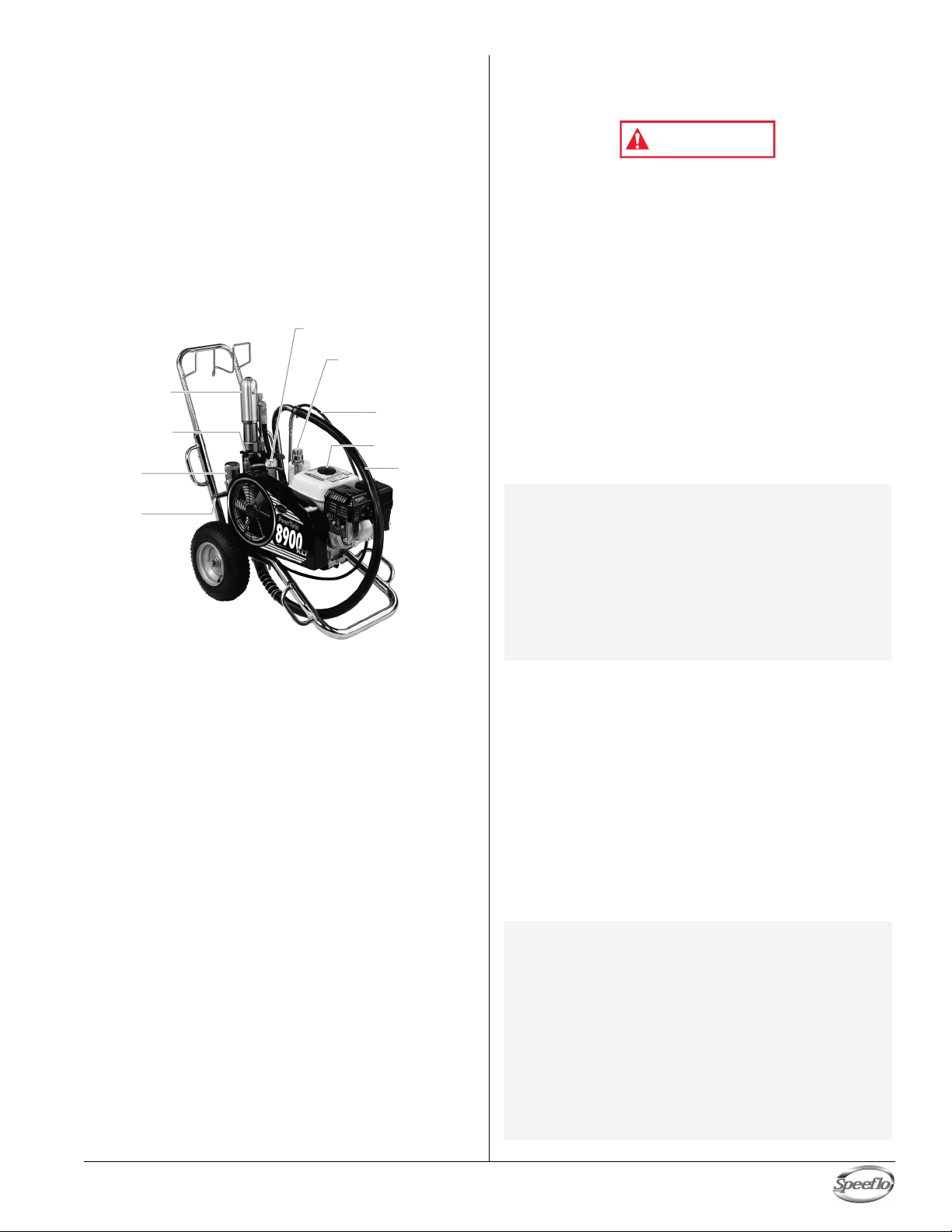
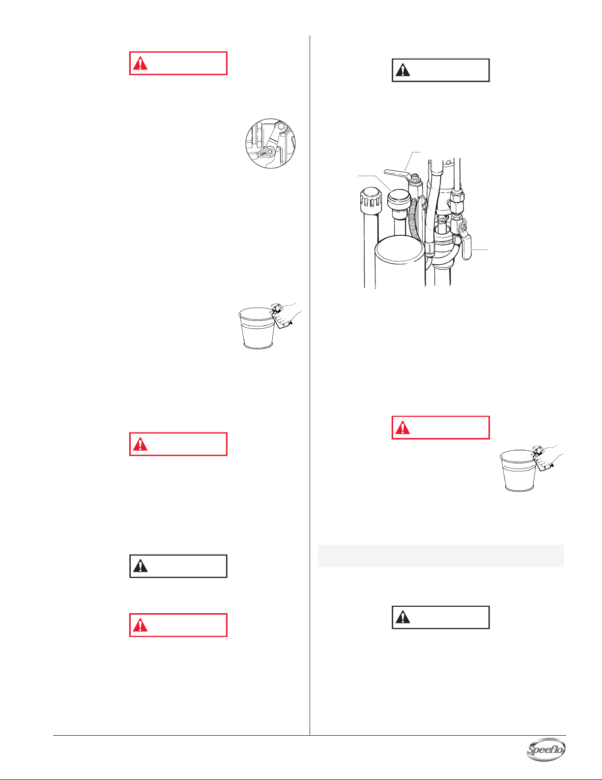
Bleed Valve
Motor/Pump
Assembly
Filter
Outlet
Fitting
Pressure Control
Knob
Bleed Hose
Siphon Hose
Hydraulic
Fluid Cap/
Dipstick
Gas Tank
WARNING
Introduction
ongratulations on having selected the finest airless sprayer
C
vailable in the world. Speeflo piston pumps are tireless
a
orkhorses — so tough they are virtually indestructible, even
w
nder the most severe service. Speeflo designs and builds
u
quipment with superior quality and reliability. Equipment that
e
ill last for years with minimal maintenance and downtime.
w
his equipment will make you money year after year. We
T
hank you for your purchase and welcome you to our large and
t
rowing family of Speeflo users.
g
The unique ability of this PowrTwin to operate with either gas
or electric power provides you with the flexibility to work
indoors or outside where no electricity is available.
Hydraulic drive makes possible the longest stroke and slowest
cycling pumps in the industry, which translates into low
maintenance and longer life. Electric units operate quietly with
no motor starting and stopping.
This PowrTwin is equipped with Speeflo's exclusive fluid
pump. This technology will give you significantly longer rod,
cylinder, and packing life than any other sprayer built in the
world. This double ball piston pump employs a dependable
and durable time-tested design. All pumps use thick, stainless
steel rod and cylinder parts. This proprietary heat-treating
process is much more abrasion resistant than any other
material used by other paint pump manufacturers. Highly
polished parts reduce friction, extend packing life, and avoid
damage from corrosion and abrasion. More than 100,000 of
these pumps are in operation around the world.
This PowrTwin offers other cost saving features:
Freeze-proof pressure control
•
• Choice of power — gas, electric, or both
ungsten carbide reversible valve seats
T
•
• Self-adjusting packings
• Exclusive hand-tight swivel foot valve
• Large capacity inline paint filter
• Waterborne compatible
• "Floating Ball" pressure bleed valve
5 gallon siphon hose and bleed line assemblies are
•
standard
ou have made an excellent choice. W
Y
pleased with your new PowrT
Speeflo. W
e appreciate your business.
win.
e know you will be
Thanks again for selecting
Operation
Fueling (gas engine)
Gasoline is extremely flammable and is explosive under
certain conditions.
• ALWAYS turn the engine off before refueling.
• Refuel in a well-ventilated area.
• Do not smoke or allow flames or sparks in the refueling
area or where gasoline is stored.
• Do not overfill the fuel tank. After refueling, make sure
the tank cap is closed properly and securely.
• Be careful not to spill fuel when refueling. Spilled fuel or
fuel vapor may ignite. If any fuel is spilled, make sure the
area is dry before starting the engine.
• Avoid repeated or prolonged contact with skin or
breathing of vapor.
• Keep out of the reach of children.
Fuel Specifications
• Use automotive gasoline that has a pump octane number
of 86 or higher, or that has a research octane number of 91
or higher. Use of a lower octane gasoline can cause
persistent "pinging" or heavy "spark knock" (a metallic
rapping noise) which, if severe, can lead to engine damage.
NOTE: If "spark knock" or "pinging" occurs at a
Gasolines Containing Alcohol
If you decide to use a gasoline containing alcohol (gasohol),
be sure its octane rating is at least as high as that
recommended by the engine manufacturer
types of "gasohol": one containing ethanol, and the other
containing methanol. Do not use gasohol that contains more
than 10% ethanol. Do not use gasoline containing methanol
(methyl or wood alcohol) that does not also contain cosolvents and corrosion inhibitors for methanol. Never use
gasoline containing more than 5% methanol, even if it has cosolvents and corrosion inhibitors.
NOTE: Fuel system damage or engine performance
steady engine speed under normal load,
change brands of gasoline. If spark knock or
pinging persists, consult an authorized dealer
of the engine manufacturer. Failure to do so is
considered misuse, and damage caused by
misuse is not covered by the engine
manufacturer’s limited warranty.
Occasionally you may experience light spark
knock while operating under heavy loads. This
is no cause for concern, it simply means your
engine is operating efficiently.
• Unleaded fuel produces fewer engine and spark plug
deposits and extends the life of the exhaust system
components.
• Never use stale or contaminated gasoline or an
oil/gasoline mixture. Avoid getting dirt, dust, or water in
the fuel tank.
. There are two
problems resulting from the use of fuels that
contain alcohol is not covered under the
warranty. The engine manufacturer cannot
endorse the use of fuels containing methanol
since evidence of their suitability is incomplete
at this time.
Before buying gasoline from an unfamiliar
station, try to find out if the gasoline contains
alcohol. If it does, confirm the type and
percentage of alcohol used. If you notice any
undesirable operating characteristics while using
a gasoline that contains alcohol, or one that you
think contains alcohol, switch to a gasoline that
you know does not contain alcohol.
© Titan Tool Inc. All rights reserved. 5
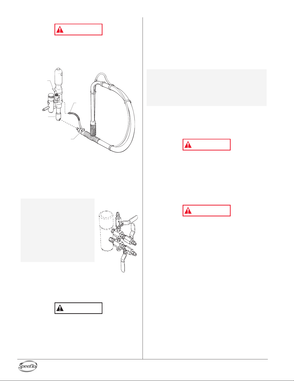
Setup
CAUTION
Multiple Gun
Manifold
Bleed
Hose
Siphon Hose
Bleed Valve
Fluid Section
WARNING
WARNING
WARNING
Read, understand, and follow all warnings before starting
or operating this sprayer.
. Connect the siphon hose to the fluid section and the bleed
1
ose to the bleed valve. They each have factory installed
h
eflon tape on the male end of the hoses and should be
T
ightened wrench tight.
t
6. For gas models, check the engine oil level daily before
starting the unit. The gasoline engine oil level is
determined by the engine manufacturer. Refer to the
engine manufacturer’s service manual supplied with this
unit.
. For electric models, use a 20 amp service outlet. Always
7
ocate the electric model within 10 to 15 feet of the service
l
utlet. Use a short electric cable and a long paint hose.
o
ny extension cord will create some voltage drop. If an
A
xtension cord is necessary, use only a grounded 3-wire
e
12 extension cord.
#
NOTE: If the unit is being operated in an area that is
8. Make sure the unit is grounded. All units are equipped
overloaded by other appliances or low voltage
conditions, it is important to start the unit
"unloaded." Tip the electric motor forward so
that the belt is loosened and the motor starts
without full load. This reduces the amperage
draw on starting and may avoid tripping the
circuit breaker.
with a grounding lug. A grounding cable (not supplied)
should be used to connect the unit to a true earth ground.
Check your local electrical regulations for detailed
grounding instructions. See the Accessories and Service
Kits section near the back of this manual for grounding
cable ordering information.
2. Attach a minimum of 50’ of nylon airless spray hose to the
unit. Do not use Teflon tape or thread sealant on the
spray hose connection.
3. Attach an airless spray gun to the spray hose. Do not
attach the tip to the spray gun yet. Remove the tip if it is
already attached.
a. To use two guns, remove the plug from the second gun
outlet on the filter assembly. Connect a hose and gun
to the outlet.
NOTE: The gas unit is
4. Fill the oil cup 1/2 full with Speeflo
5. Check the hydraulic fluid level daily before starting the
engineered to handle up
to 5 guns with .024" tips
and the electric unit is
engineered to handle up
to 3 guns with .019” tips.
For multiple gun
operation, connect a
multiple gun manifold to
the single gun outlet.
Connect a hose and gun
to each outlet. Make
sure the second gun
outlet remains plugged.
Piston Lube (P/N 314-480) supplied
by the factory
life.
unit. The hydraulic fluid level should be at the “Full” mark
on the dipstick. Refer to the Maintenance section of this
manual for hydraulic system maintenance instructions.
This extends packing
.
Proper grounding is important. This applies to both gas
and electric powered models. The passage of some
materials through the nylon fluid hose will build up a
static electric charge, which if discharged, could ignite
solvent vapors present and create an explosion.
9. Strain all paints with a nylon strainer to ensure trouble free
operation and freedom from frequent cleaning of the inlet
screen and gun filter.
10 Make sure the spray area is well ventilated to prevent
hazardous operation with volatile solvents or exhaust
fumes.
If lacquer or other flammable materials are to be sprayed,
ALWAYS locate the unit outside the immediate spraying
area. Failure to do so may cause an explosion.
11. Locate the unit outside the immediate spraying area to
avoid clogged air intake of the engine or electric motor
with overspray.
Use of Speeflo's Coolflo
the hydraulic system. Do not use any other hydraulic
fluid. Use of any other hydraulic fluid may seriously
damage the hydraulic system and will void the warranty
™
English
Hydraulic Fluid is mandatory in
.
6 © Titan Tool Inc. All rights reserved.
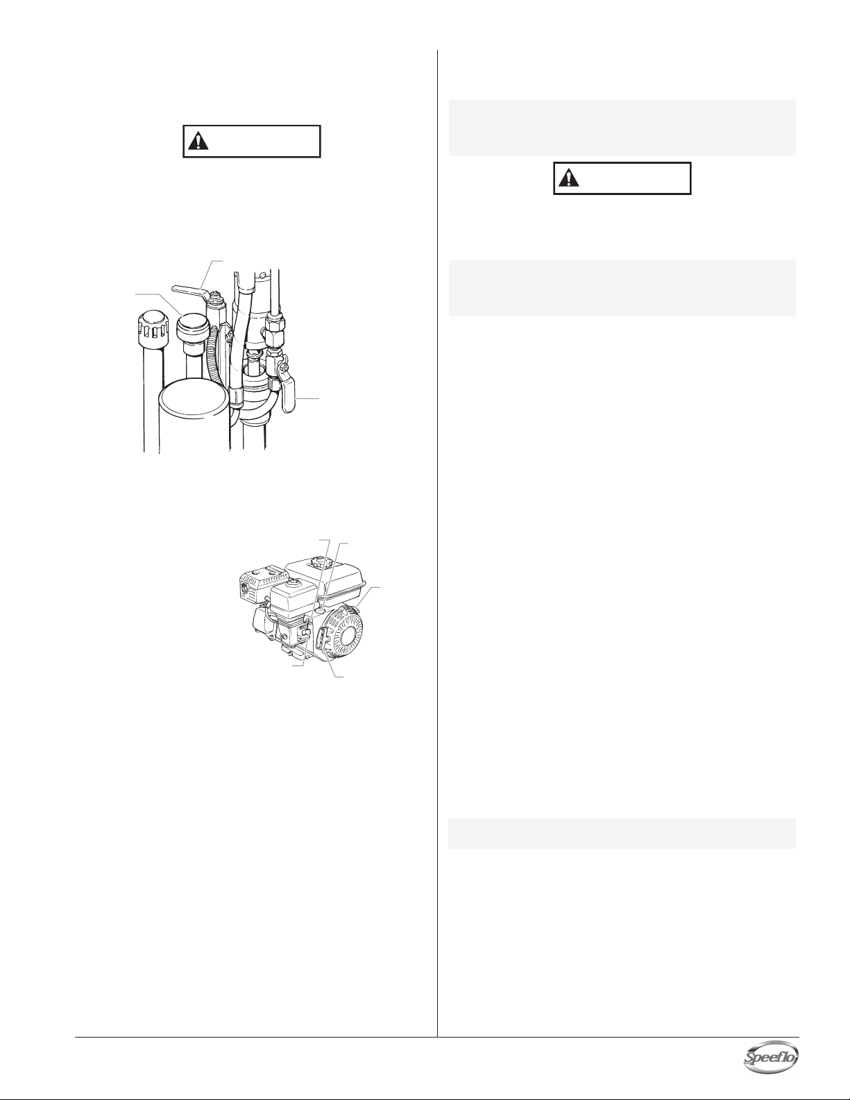
Fuel Valve
Lever
Choke Lever
Engine
Switch
Throttle
Lever
Starter Rope
Pressure
Control
Knob
Bleed Valve
Hydraulic Shut-off
Valve (in open
position)
CAUTION
CAUTION
P
reparing a New Sprayer
If this unit is new, it is shipped with test fluid in the fluid section
to prevent corrosion during shipment and storage. This fluid
must be thoroughly cleaned out of the system with mineral
spirits before you begin spraying.
Always keep the trigger lock on the spray gun in the
locked position while preparing the system.
1. Place the siphon hose into a container of mineral spirits.
. Place the bleed hose into a metal waste container.
2
. Set the pressure to minimum by turning the pressure
3
ontrol knob fully counterclockwise.
c
4. Open the hydraulic shut-off valve located on the hydraulic
pressure hose. The handle should be in line with the hose.
5. Open the bleed valve by rotating the bleed valve handle
fully counterclockwise.
6. Start the engine or turn on the electric motor.
a. To start the gas
engine,
• move the fuel
valve lever to
the open
position,
• move the
throttle lever to
its middle point,
• move the choke
lever to the
closed position
for a cold engine or to the open position for a warm
engine,
• turn the engine switch to the ON position, and
• pull the starter rope briskly until the engine starts.
b. To start the electric motor, move the ON/OFF switch to
the ON position.
7. Turn the pressure control knob clockwise approximately
1/3 of the way down to increase pressure until the sprayer
cycles evenly and solvent flows freely from the bleed hose.
8. Allow the sprayer to run for 15–30 seconds to flush the
test fluid out through the bleed hose and into the waste
container.
9. Turn off the unit.
a. To turn off the gas engine,
set the pressure to minimum by turning the pressure
•
control knob fully counterclockwise,
• move the throttle lever to the slow position, and
turn the engine switch to the OFF position.
•
b. To turn off the electric motor,
• set the pressure to minimum by turning the pressure
control knob fully counterclockwise,
• move the ON/OFF switch to the OFF position.
Preparing to Paint
Before painting, it is important to make sure that the fluid in the
system is compatible with the paint that is going to be used.
NOTE: Incompatible fluids and paint may cause the
Always keep the trigger lock on the spray gun in the
locked position while preparing the system.
1. Place the siphon hose into a container of the appropriate
N
2. Place the bleed hose into a metal waste container.
3. Set the pressure to minimum by turning the pressure
4. Open the hydraulic shut-off valve located on the hydraulic
5. Open the bleed valve by rotating the bleed valve handle
6. Start the engine or turn on the electric motor.
7. Turn the pressure control knob clockwise approximately
8. Allow the sprayer to run for 15–30 seconds to flush the
9. Turn off the unit.
NOTE:
10.
11. Start the engine or turn on the electric motor.
12. Turn the pressure control knob clockwise approximately
13. Unlock the gun by turning the gun trigger lock to the
valves to become stuck closed, which would
require disassembly and cleaning of the
sprayer’s fluid section.
solvent.
OTE: If you are spraying a water-based latex, flush
ith warm, clean water. If you are using any
w
ther material, check with the material
o
manufacturer for a compatible solvent.
control knob fully counterclockwise.
pressure hose. The handle should be in line with the hose.
fully counterclockwise.
a. To start the gas engine,
• move the fuel valve lever to the open position,
• move the throttle lever to its middle point,
• move the choke lever to the closed position for a
cold engine or to the open position for a warm
engine,
• turn the engine switch to the ON position, and
• pull the starter rope briskly until the engine starts.
b. To start the electric motor, move the ON/OFF switch to
the ON position.
1/3 of the way down to increase pressure until the sprayer
cycles evenly and solvent flows freely from the bleed hose.
test fluid out through the bleed hose and into the waste
container.
a. To turn off the gas engine,
• set the pressure to minimum by turning the pressure
control knob fully counterclockwise,
• move the throttle lever to the slow position, and
• turn the engine switch to the OFF position.
b. To turn off the electric motor,
set the pressure to minimum by turning the pressure
•
control knob fully counterclockwise,
move the ON/OFF switch to the OFF position.
•
Make sure that the spray gun does not have a
tip or tip guard installed.
Close the bleed valve by rotating the bleed valve handle
fully clockwise.
1/3 of the way down to increase pressure.
unlocked position.
© Titan Tool Inc. All rights reserved. 7
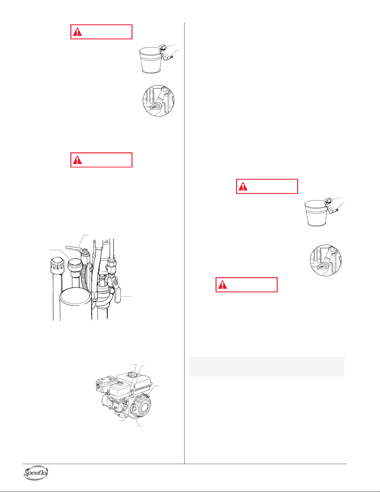
Ground the gun by holding it against the
Fuel Valve
Lever
Choke Lever
Engine
Switch
Throttle
Lever
Starter Rope
Pressure
Control
Knob
Bleed Valve
Hydraulic Shut-off
Valve (in open
position)
WARNING
Trigger lock in
locked position.
WARNING
WARNING
Trigger lock in
locked position.
WARNING
edge of the metal container while flushing.
Failure to do so may lead to a static
electric discharge, which may cause a fire.
14. Trigger the gun into the metal waste
container until the old solvent is gone
and fresh solvent is coming out of the gun.
15. Lock the gun by turning the gun trigger
lock to the locked position.
16. Set down the gun and increase the
pressure by turning the pressure control
knob slowly clockwise.
7. Check the entire system for leaks. If
1
eaks occur, follow the “Pressure Relief
l
Procedure” in this manual before
tightening any fittings or hoses.
18. Follow the “Pressure Relief Procedure” in this manual
before changing from solvent to paint.
Be sure to follow the pressure relief procedure when
shutting the unit down for any purpose, including
servicing or adjusting any part of the spray system,
changing or cleaning spray tips, or preparing for cleanup.
Painting
1. Place the siphon hose into a container of paint.
2. Place the bleed hose into a metal waste container.
3. Set the pressure to minimum by turning the pressure
control knob fully counterclockwise.
b. To start the electric motor, move the ON/OFF switch to
the ON position.
7. Turn the pressure control knob clockwise approximately
1/3 of the way down to increase pressure until the sprayer
cycles evenly and paint flows freely from the bleed hose.
8. Turn off the unit.
a. To turn off the gas engine,
• set the pressure to minimum by turning the pressure
control knob fully counterclockwise,
move the throttle lever to the slow position, and
•
• turn the engine switch to the OFF position.
b. To turn off the electric motor,
• set the pressure to minimum by turning the pressure
control knob fully counterclockwise,
• move the ON/OFF switch to the OFF position.
9. Remove the bleed hose from the waste container and
place it into the container of paint.
10. Close the bleed valve by rotating the bleed valve handle
fully clockwise.
11. Start the engine or turn on the electric motor.
12. Turn the pressure control knob clockwise approximately
1/3 of the way down to increase pressure.
13. Unlock the gun by turning the gun trigger lock to the
unlocked position.
Ground the gun by holding it against the
edge of the metal container while
flushing. Failure to do so may lead to a
static electric discharge, which may cause
a fire.
14. Trigger the gun into the metal waste container until all air
and solvent is flushed from the spray hose and paint is
flowing freely. from the gun.
15. Lock the gun by turning the gun trigger
lock to the locked position.
16. Turn off the unit.
17. Attach tip guard and tip to the gun as
instructed by the tip guard or tip manuals.
4. Open the hydraulic shut-off valve located on the hydraulic
pressure hose. The handle should be in line with the hose.
5. Open the bleed valve by rotating the bleed valve handle
fully counterclockwise.
6. Start the engine or turn on the electric motor
a. To start the gas engine,
.
move the fuel
•
valve lever to
the open
position,
• move the
throttle lever to
its middle point,
move the choke
•
lever to the
closed position
for a cold
engine or to the
open position for a warm engine,
• turn the engine switch to the ON position, and
pull the starter rope briskly until the engine starts.
•
English
POSSIBLE INJECTION HAZARD. Do not spray without the
tip guard in place. Never trigger the gun unless the tip is
in either the spray or the unclog position. Always engage
the gun trigger lock before removing, replacing or
cleaning tip.
18. Start the engine or turn on the electric motor.
19. Increase the pressure by turning the pressure control
knob slowly clockwise and test the spray pattern on a
piece of cardboard. Adjust the pressure control knob until
the spray from the gun is completely atomized.
NOTE: T
8 © Titan Tool Inc. All rights reserved.
urning the pressure up higher then needed to
atomize the paint will cause premature tip wear
and additional overspray.
Pressure Relief Procedure
WARNING
CAUTION
WARNING
T
rigger lock in
l
ocked position.
WARNING
CAUTION
WARNING
Pressure
Control
Knob
Bleed Valve
Hydraulic Shut-off
Valve (in open
position)
CAUTION
3. Place the siphon tube into a container of the appropriate
solvent.
Be sure to follow the pressure relief procedure when
shutting the unit down for any purpose, including
servicing or adjusting any part of the spray system,
changing or cleaning spray tips, or preparing for cleanup.
. Lock the gun by turning the gun trigger
1
ock to the locked position.
l
2. Turn off the unit.
. To turn off the gas engine,
a
• set the pressure to minimum by
turning the pressure control knob
fully counterclockwise,
• move the throttle lever to the slow
position, and
• turn the engine switch to the OFF position.
b. To turn off the electric motor,
• set the pressure to minimum by turning the pressure
control knob fully counterclockwise,
• move the ON/OFF switch to the OFF position.
3. Close the hydraulic shut-off valve on the hydraulic
pressure hose.
4. Unlock the gun by turning the gun trigger lock to the
unlocked position.
5. Hold the metal part of the gun firmly to
the side of a metal waste container to
ground the gun and avoid a build up of
static electricity.
6. Trigger the gun to remove any pressure
that may still be in the hose.
7. Lock the gun by turning the gun trigger lock to the locked
position.
8. Place the bleed hose into the metal waste container.
9. Open the bleed valve by rotating the bleed valve handle
fully counterclockwise.
Cleanup
Use only compatible solvents when cleaning out oil based
enamels, lacquers, coal tar, and epoxies. Check with the
fluid manufacturer for the recommended solvent.
4. Place the bleed hose into a metal waste container.
. Set the pressure to minimum by turning the pressure
5
ontrol knob fully counterclockwise.
c
6. Open the hydraulic shut-off valve located on the hydraulic
pressure hose. The handle should be in line with the hose.
7. Open the bleed valve by rotating the bleed valve handle
fully counterclockwise.
8. Start the engine or turn on the electric motor.
9. Allow the solvent to circulate through the unit and flush
the paint out of the bleed hose into the metal waste
container.
10. Turn off the unit.
11. Close the bleed valve by rotating the bleed valve handle
fully clockwise.
12. Start the engine or turn on the electric motor.
Special cleanup instructions for use with flammable
solvents:
The sprayer, hose, and gun should be cleaned thoroughly
after daily use. Failure to do so permits material to build
up, seriously affecting the performance of the unit.
Always spray at minimum pressure with the gun nozzle tip
removed when using mineral spirits or any other solvent
to clean the sprayer, hose, or gun. Static electricity
buildup may result in a fire or explosion in the presence of
flammable vapors.
© Titan Tool Inc. All rights reserved. 9
Always flush spray gun preferably outside and at least one
•
hose length from spray pump.
If collecting flushed solvents in a one gallon metal
•
container, place it into an empty five gallon container
flush solvents.
Area must be free of flammable vapors.
•
Follow all cleanup instructions.
•
1. Follow the “Pressure Relief Procedure” found in the
Operation section of this manual.
2. Remove the gun tip and tip guard and clean with a brush
using the appropriate solvent.
, then
Ground the gun by holding it against the
edge of the metal container while
flushing. Failure to do so may lead to a
static electric discharge, which may cause
a fire.
13. Trigger the gun into the metal waste container until the
paint is flushed out of the hose and solvent is coming out
of the gun.
14. Continue to trigger the spray gun into the waste container
until the solvent coming out of the gun is clean.
NOTE: For long-term or cold weather storage, pump
mineral sprits through the entire system.
15. Follow the “Pressure Relief Procedure” found in the
Operation section of this manual.
16. Store the unit in a clean, dry area.
Do not store the unit under pressure.
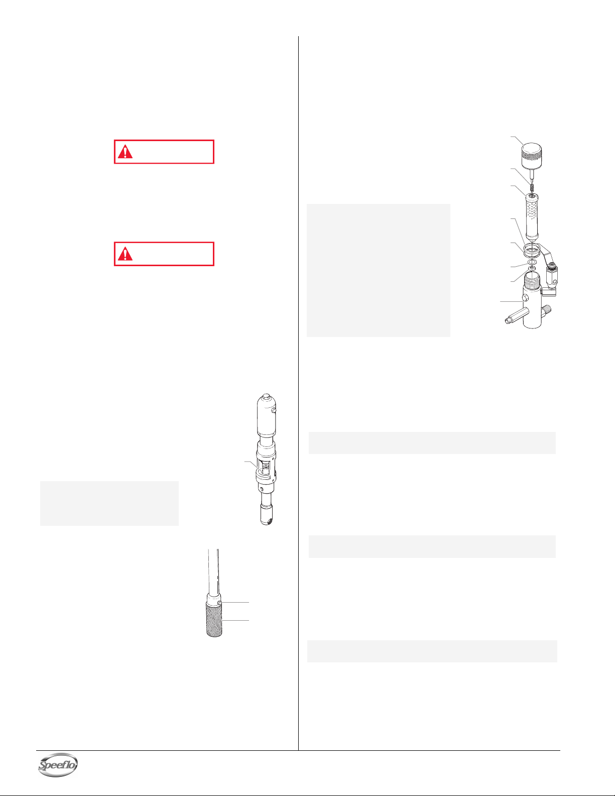
Cleaning a Clogged Tip
Rock
Catcher
Nut
Packing Oil
Reservoir
WARNING
WARNING
F
ilter Cap
A
ssembly
Filter
Element
w/Ball
Teflon Gasket
(thick)
Teflon Gasket
(thin)
Teflon O-ring
Carbide Seat
Filter
Body
Spring
1. Follow the “Pressure Relief Procedure” in the Operation
section of this manual.
2. If the tip clogs, rotate the tip handle 180° until the arrow
on the handle is facing the opposite of the spray direction
and the handle clicks in the reverse position.
3. Trigger the gun once so that the pressure can blow the
clog out. NEVER use the tip in the reverse position for
more than ONE trigger pull at a time. This procedure can
be repeated until the tip is free of clogging.
he flow from the spray tip is at very high pressure.
T
ontact with any body part may be dangerous. Do not
C
lace finger on gun outlet. Do not point the gun at any
p
erson. Never operate the spray gun without the proper
p
ip guard.
t
Maintenance
Before proceeding, follow the Pressure Relief Procedure
outlined previously in this manual. Additionally, follow all
other warnings to reduce the risk of an injection injury,
injury from moving parts or electric shock. Always unplug
the sprayer before servicing!
Daily Maintenance
Two daily procedures are required for routine operator
maintenance on this unit:
1. Lubricating the upper packings.
2. Cleaning the rock catcher.
Lubricating the Upper Packings
1. Clean out the paint that has
seeped past the upper
packings into the packing oil
reservoir above the fluid
section.
2. Fill the packing oil reservoir 1/2
full with Piston Lube (P/N 314-
480) supplied by the factory.
This will extend packing life.
NOTE: Do not over-fill the
Cleaning the Rock Catcher
1. The rock catcher will clog and
must be cleaned at least once a
day.
Loosen the nut that secures the
2.
rock catcher to the siphon tube.
3. Remove the rock catcher from the
bottom of the siphon tube.
4. Clean thoroughly with the
appropriate solvent.
reservoir so that it
overflows and drips
into the paint.
English
Maintaining the Filter Assembly
Clean the filter regularly. Dirty or clogged filters can greatly
reduce filtering ability and cause a number of system problems
including poor spray patterns, clogged spray tips, etc.
Cleaning
To clean the filter, perform the following procedure.
1. Follow the “Pressure Relief Procedure” found in the
Operation section of this manual.
2. Remove the filter cap assembly
and spring.
3. Pull the filter element with ball
straight out of the filter body.
. Clean inside the filter body,
4
ilter element with ball, and filter
f
ap assembly using the
c
ppropriate solvent.
a
OTE: Use care in handling
N
Inspection
Inspect all parts of the filter assembly before reassembly.
1. Inspect the ball inside the filter element. If the ball has
NOTE: Removal of the Teflon o-ring will damage the
2. Remove the spring from the spring guide on the filter cap.
3. Inspect the two
NOTE:
Reassembly
After cleaning and inspecting all parts, reassemble the filter.
1. Place the carbide seat into the filter body. Make sure the
2. Place the Teflon o-ring into the groove on the outer
3. Place the filter element with ball into the filter body.
NOTE: The top and bottom of the filter element with
4. Push the spring back onto the spring guide of the filter cap
5. Place the thin Teflon gasket onto the step at the top of the
6. Place the thick Teflon gasket onto the top of the thin
7. Tighten the filter cap assembly onto the filter body.
10 © Titan Tool Inc. All rights reserved.
parts as dirt, debris,
scratches, or nicks
may prevent o-rings or
gaskets from sealing.
This filter element
filters from the inside
out. Be sure to clean
the filter element
thoroughly on the
inside. Soak in
solvent to loosen
hardened paint or
replace.
pressure cuts or scratches, replace the filter element.
a. If the ball is cut, remove the Teflon o-ring using an o-
ring pick and remove the carbide seat.
b. Check the seat for nicks or grooves. If the seat is
damaged, replace.
o-ring and require replacement.
a. Measure the length of the spring uncompressed. If it
measures less than 3/4” from end to end, replace.
b. Push the spring back onto the spring guide until it
“snaps” back into position.
deformity, nicks, or cuts. Replace, if needed.
The T
are packaged in Filter Service Kit P/N 930-050.
beveled side of the seat is facing up.
diameter of the carbide seat.
ball are identical.
until it “snaps” back into position, if not already done.
filter body.
gasket.
Teflon gaskets and the Teflon o-ring for
eflon gaskets, Teflon o-ring, and spring
 Loading...