

Page 1
Owner’s Manual
For professional use only
Do not use this equipment before reading this manual!
NOTE: This manual contains
important warnings
and instructions.
lease read and retain
P
for reference.
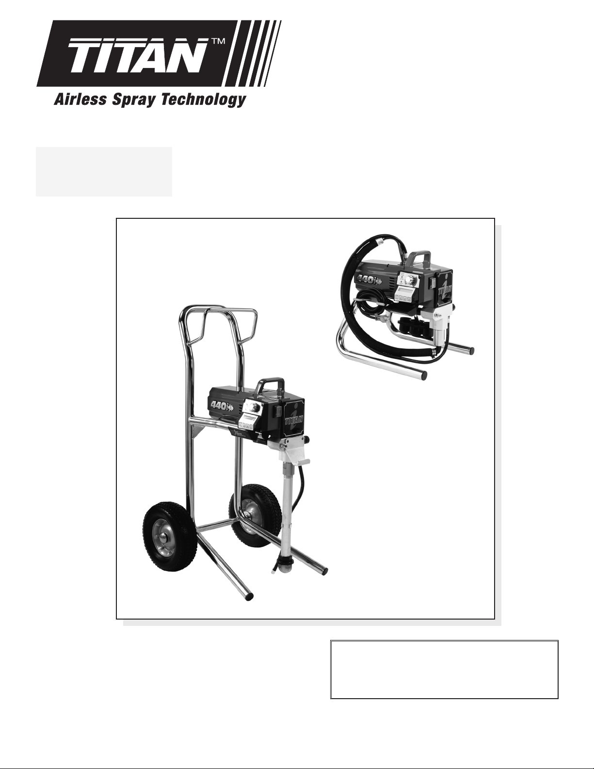
440ix
Airless Sprayer
Model Numbers:
Skid Basic 700-3030
Skid Loaded 700-3035
High Rider Basic
High Rider L
Printed in the U. S.
A.
oaded
700-3040
700-3045
X-Lock Theft Deterrent System
Security Code
— — — —
itan Tool Inc. All rights reserved. Form No. 313-2459A
T
2005
©
0105
Page 2
Table of Contents
WARNING
CAUTION
WARNING
afety Precautions.................................................................2
S
pecifications .........................................................................3
S
eneral Description ...............................................................4
G
peration ................................................................................4
O
etup ....................................................................................4
S
reparing to Paint.................................................................4
P
ainting.................................................................................5
P
ontrol Panel Indicators .......................................................5
C
act Digital Control System Operation.................................6
X
ressure Relief Procedure ...................................................7
P
praying ..................................................................................8
S
praying Technique ..............................................................8
S
ractice.................................................................................8
P
leanup ...................................................................................9
C
aintenance............................................................................9
M
eneral Repair and Service Notes.......................................9
G
eplacing the Motor ...........................................................10
R
eplacing the Gears...........................................................10
R
Replacing the Transducer...................................................11
Replacing the PRIME/SPRAY Valve...................................11
Servicing the Fluid Section.................................................12
Replacing the Filters...........................................................13
roubleshooting ...................................................................14
T
Xact Digital Control System Error Messages
Parts Listings
Main
Assembly ....................................................................21
Skid
Siphon Assembly ................................................................21
Fluid Section Assembly ......................................................22
Drive Assembly...................................................................23
High Rider Cart Assembly ..................................................24
Labels .................................................................................24
Electrical Schematic ...........................................................24
Accessories ........................................................................25
Warranty................................................................................28
........................................................................20
Assembly....................................................................20
.....................15
Safety Precautions
This manual contains information that must be read and
understood before using the equipment. When you come to an
area that has one of the following symbols, pay particular
attention and make certain to heed the safeguard.
This symbol indicates a potential hazard that may cause
serious injury or loss of life. Important safety information will
follow.
This symbol indicates a potential hazard to you or to the
equipment. Important information that tells how to prevent
damage to the equipment or how to avoid causes of minor
injuries will follow
NOTE: Notes give important information which should
HAZARD: Injection injury -
DO NOT TREAT AN INJECTION INJURY AS A SIMPLE
CUT! Injection can lead to amputation. See a physician
immediately.
The maximum operating range of the sprayer is 3300 PSI/
22.8 MPa fluid pressure.
PREVENTION:
• NEVER aim the gun at any part of the body.
.
be given special attention.
produced by this equipment can pierce the
skin and underlying tissues, leading to serious
injury and possible amputation. See a
physician immediately
A high pressure fluid stream
.
• NEVER allow any part of the body to touch the fluid stream.
DO NOT allow body to touch a leak in the fluid hose.
• NEVER put hand in front of the gun. Gloves will not
provide protection against an injection injury.
• ALWAYS lock gun trigger, shut pump off, and release all
pressure before servicing, cleaning tip or guard, changing
tip, or leaving unattended. Pressure will not be released
by turning off the motor. The PRIME/SPRAY valve handle
must be turned to PRIME to relieve the pressure. Refer to
the PRESSURE RELIEF PRESSURE described in the
pump manual.
• ALWAYS keep tip guard in place while spraying. The tip
guard provides some protection but is mainly a warning
device.
• ALWAYS remove the spray tip before flushing or cleaning
the system.
• Paint hose can develop leaks from wear, kinking and
abuse. A leak can inject material into the skin. Inspect
the hose before each use.
• NEVER use a spray gun without a working trigger lock
and trigger guard in place.
• All accessories must be rated at or above the maximum
operating pressure range of the airless sprayer. This
includes spray tips, guns, extensions, and hose.
NOTE TO PHYSICIAN:
Injection into the skin is a traumatic injury. It is
important to treat the injury as soon as possible. DO
NOT delay treatment to research toxicity. Toxicity is a
concern with some coatings injected directly into the
blood stream. Consultation with a plastic surgeon or
reconstructive hand surgeon may be advisable.
HAZARD: EXPLOSION AND FIRE - Solvent and paint
fumes can explode or ignite. Severe injury
and/or property damage can occur.
PREVENTION:
• Provide extensive exhaust and fresh air introduction to
keep the air within the spray area free from accumulation
of flammable vapors.
• Avoid all ignition sources such as static electricity sparks,
electrical appliances, flames, pilot lights, hot objects, and
sparks from connecting and disconnecting power cords or
working light switches.
• Do not smoke in spray area.
• Fire extinguisher must be present and in good working
order.
• Place pump at least 25 feet (7.6 m) from the spray object
in a well ventilated area (add more hose if necessary).
Flammable vapors are often heavier than air. Floor area
must be extremely well ventilated. The pump contains
arcing parts that emit sparks and can ignite vapors.
• The equipment and objects in and around the spray area
must be properly grounded to prevent static sparks.
• Use only conductive or grounded high-pressure fluid hose.
Gun must be grounded through hose connections.
• Power cord must be connected to a grounded circuit.
• Always flush unit into separate metal container, at low
pump pressure, with spray tip removed. Hold gun firmly
against side of container to ground container and prevent
static sparks.
• Follow material and solvent manufacturer's warnings and
instructions.
• Use extreme caution when using materials with a
flashpoint below 70° F (21° C). Flashpoint is the
temperature at which a fluid can produce enough vapors
to ignite.
• Plastic can cause static sparks. Never hang plastic to
enclose spray area. Do not use plastic drop cloths when
spraying flammable materials.
• Use lowest possible pressure to flush equipment.
2 © Titan Tool Inc. All rights reserved.
Page 3
GAS ENGINE (WHERE APPLICABLE)
CAUTION
CAUTION
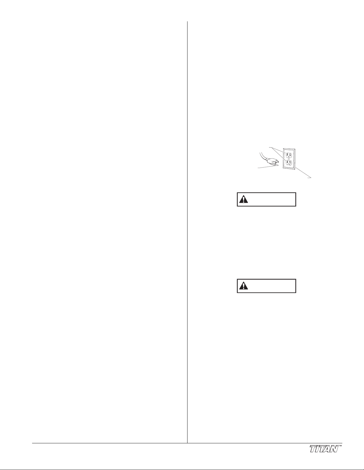
Grounded Outlet
Grounding Pin
Cover for grounded outlet box
lways place sprayer outside of structure in fresh air. Keep all
A
olvents away from engine exhaust. Never fill fuel tank with a
s
unning or hot engine. Hot surface can ignite spilled fuel.
r
lways attach ground wire from pump to a grounded object.
A
efer to engine owner’s manual for complete safety information.
R
HAZARD: EXPLOSION HAZARD DUE TO INCOMPATIBLE
PREVENTION:
• Do not use materials containing bleach or chlorine.
• Do not use halogenated hydrocarbon solvents such as
•
HAZARD: HAZARDOUS VAPORS - Paints, solvents,
PREVENTION:
• Use a respirator or mask if vapors can be inhaled. Read
• Wear protective eyewear.
• Wear protective clothing as required by coating
HAZARD: GENERAL - Can cause severe injury or
PREVENTION:
• Read all instructions and safety precautions before
• Follow all appropriate local, state, and national codes
• The United States Government Safety Standards have
• Use only manufacturer authorized parts. User assumes
•
• All hoses, swivels, guns, and accessories must be
• Do not spray outdoors on windy days.
• Wear clothing to keep paint off skin and hair.
• Always unplug cord from outlet before working on equipment.
MATERIALS - will cause severe injury or
property damage.
bleach, mildewcide, methylene chloride and 1,1,1 trichloroethane. They are not compatible with aluminum.
Contact your coating supplier about the compatibility of
aterial with aluminum.
m
insecticides, and other materials can be
harmful if inhaled or come in contact with body.
Vapors can cause severe nausea, fainting, or
poisoning.
all instructions supplied with the mask to be sure it will
provide the necessary protection.
manufacturer.
property damage.
operating equipment.
governing ventilation, fire prevention, and operation.
been adopted under the Occupational Safety and Health
Act (OSHA). These standards, particularly part 1910 of
the General Standards and part 1926 of the Construction
Standards, should be consulted.
all risks and liabilities when using parts that do not meet
the minimum specifications and safety devices of the
pump manufacturer.
Before each use, check all hoses for cuts, leaks, abrasion
or bulging of cover
couplings. Immediately replace hose if any of those
conditions exist. Never repair a paint hose. Replace with
a grounded high-pressure hose.
pressure rated at or above the maximum operating
pressure range of the airless sprayer.
. Check for damage or movement of
Grounding Instructions
This product must be grounded. In the event of an electrical
short circuit, grounding reduces the risk of electric shock by
providing an escape wire for the electric current. This product
is equipped with a cord having a grounding wire with an
appropriate grounding plug. The plug must be plugged into an
outlet that is properly installed and grounded in accordance
with all local codes and ordinances.
DANGER — Improper installation of the grounding plug can
result in a risk of electric shock. If repair or replacement of the
cord or plug is necessary, do not connect the green grounding
wire to either flat blade terminal. The wire with insulation
having a green outer surface with or without yellow stripes is
the grounding wire and must be connected to the grounding
pin.
Check with a qualified electrician or serviceman if the
grounding instructions are not completely understood, or if you
are in doubt as to whether the product is properly grounded.
Do not modify the plug provided. If the plug will not fit the
outlet, have the proper outlet installed by a qualified
electrician.
Use only a 3-wire extension cord that has a 3-blade
grounding plug and a 3-slot receptacle that will accept the
plug on the product. Make sure the extension cord is in
good condition. When using an extension cord, be sure
to use one heavy enough to carry the current the product
will draw. An undersized cord will cause a drop in line
voltage resulting in loss of power and overheating. A 12
gauge cord is recommended. If an extension cord is to be
used outdoors, it must be marked with the suffix W-A after
the cord type designation. For example, a designation of
SJTW-A would indicate that the cord would be appropriate
for outdoor use.
When the sprayer is used with a generator or uncontrolled
line voltage, the use of Titan’s “Line Surge Protector” (P/N
800-935) is recommended.
Specifications
Gallons per minute (GPM)...............0.50 (1.9 LPM)
Maximum tip sizes ...........................
Maximum pressure
Power...............................................1.15 HP Infinity Brushless
eight, Skid
W
Weight, High Rider...........................55 lbs. (24.9 kg)
Maximum hose length......................300’ (91.4 m)
..........................3300 PSI (22.8 MPa)
.....................................30 lbs. (13.6 kg)
0.022”
DC motor
© Titan Tool Inc. All rights reserved. 3
Page 4
General Description
CAUTION
WARNING
WARNING
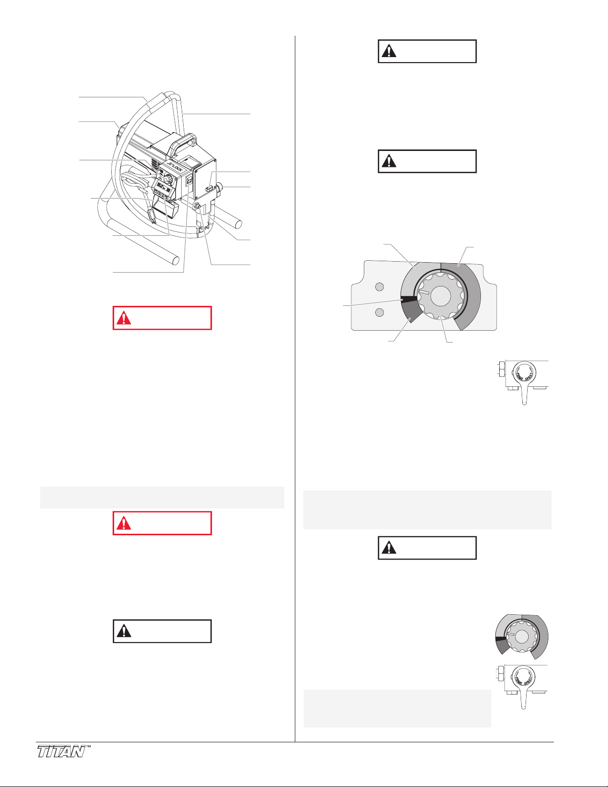
ON/OFF
Switch
Motor
Siphon
Tube
Xact Digital
Control System
(Optional)
Control
System
Cover
Pressure
Control
Knob
O
il Cup
Outlet
Fitting
Fluid
Section
Return
Hose
PRIME/
SPRAY
Valve
Min PSI
(Bar)
Max PSI
(
Bar)
Pulse
Clean
CAUTION
Min PSI
(Bar)
Max PSI
(Bar)
Blinking Yellow
0-200 PSI
Solid Yellow
201-1900 PSI
Solid Green
1901-3300 PSI
Motor Running
Pulse
Clean
Min. – 1900 PSI
(yellow zone)
1901 – 3300 PSI
(green zone)
Turbo PulseClean
(red zone)
OFF
(black
zone)
Pressure
Control Knob
CAUTION
CAUTION
This airless sprayer is a precision power tool used for spraying
many types of materials. Read and follow this instruction
manual carefully for proper operating instructions,
maintenance, and safety information.
Operation
lways use a minimum 12 gauge, three-wire extension cord
A
ith a grounded plug. Never remove the third prong or use
w
n adapter.
a
Preparing a New Sprayer
If this sprayer is new, it is shipped with test fluid in the fluid
section to prevent corrosion during shipment and storage.
This fluid must be thoroughly cleaned out of the system with
mineral spirits before you begin spraying.
Always keep the trigger lock on the spray gun in the
locked position while preparing the system.
1. Place the siphon tube into a container of mineral spirits.
2. Place the return hose into a metal waste container.
3. Set the pressure to minimum by turning the pressure
control knob to the “Min” setting in the yellow zone.
This equipment produces a fluid stream at extremely high
pressure. Read and understand the warnings in the
Safety Precautions section at the front of this manual
before operating this equipment.
Setup
Perform the following procedure before plugging in the power
cord of an electric unit.
1. Ensure that the siphon tube and the return hose are
attached and secure.
2. Using a wrench, attach a minimum of 50’ of 1/4” nylon
airless spray hose to the outlet fitting on the sprayer.
Tighten securely.
3. Attach an airless spray gun to the spray hose. Using two
wrenches (one on the gun and one on the hose), tighten
securely
NOTE: Do not attach the tip to the spray gun yet.
Make sure all airless hoses and spray guns are electrically
grounded and rated at or above the maximum operating
pressure range of the airless sprayer.
4. Make sure the pressure control knob is in its OFF position
in the black zone.
5. Make sure the ON/OFF switch is in its OFF position.
6. Fill the oil cup with one tablespoon of piston seal lubricant
(Piston Lube).
Never operate unit for more than ten seconds without
fluid. Operating this unit without fluid will cause
unnecessary wear to the packings.
7. Make sure the electrical service is 120V, 15 amp
minimum.
8. Plug the power cord into a properly grounded outlet at
least 25’ from the spray area.
.
Remove the tip if it is already attached.
4. Move the PRIME/SPRAY valve down to
the PRIME position.
5. Turn on the sprayer by moving the
ON/OFF switch to the ON position.
6. Allow the sprayer to run for 15–30 seconds
to flush the test fluid out through the return hose and into
the waste container.
7. Turn off the sprayer by moving the ON/OFF switch to the
OFF position.
Preparing to Paint
Before painting, it is important to make sure that the fluid in the
system is compatible with the paint that is going to be used.
NOTE: Incompatible fluids and paint may cause the
Always keep the trigger lock on the spray gun in the
locked position while preparing the system.
1.
2. Place the return hose into a metal waste
3.
4. Move the PRIME/SPRAY valve down to the
NOTE: Hold the return hose in the waste
4 © Titan Tool Inc. All rights reserved.
valves to become stuck closed, which would
require disassembly and cleaning of the
sprayer’s fluid section.
Place the siphon tube into a container of the appropriate
solvent. Examples of the appropriate solvent are water for
latex paint or mineral spirits for oil-based paints.
container.
Set the pressure to minimum by turning
the pressure control knob to the “Min”
setting in the yellow zone.
PRIME position.
container when moving the
PRIME/SPRAY valve to PRIME in
case the sprayer is pressurized.
Page 5

5. Turn on the sprayer by moving the ON/OFF switch to the
Min PSI
(Bar)
Max PSI
(Bar)
Pulse
Clean
WARNING
Trigger lock in
locked position.
WARNING
M
in PSI
(Bar)
Max PSI
(Bar)
Blinking Yellow
0-200 PSI
Solid Yellow
201-1900 PSI
Solid Green
1901-3300 PSI
Motor Running
Pulse
Clean
Pressure
Indicator
Motor Running
Indicator
WARNING
Trigger lock in
locked position.
WARNING
ON position.
. Allow the sprayer to run for 15–30 seconds to flush the old
6
olvent out through the return hose and into the metal
s
aste container.
w
7. Turn off the sprayer by moving the ON/OFF switch to the
OFF position.
OTE: Make sure that the spray gun does not have a
N
ip or tip guard installed.
t
8. Move the PRIME/SPRAY valve up to the
SPRAY position.
9. Turn on the sprayer.
0. Unlock the gun by turning the gun trigger
1
ock to the unlocked position.
l
Ground the gun by holding it against the
edge of the metal container while flushing.
Failure to do so may lead to a static
electric discharge, which may cause a fire.
2. Trigger the gun into the metal waste
1
ontainer until all air and solvent is flushed from the spray
c
ose and paint is flowing freely. from the gun.
h
3. Lock the gun by turning the gun trigger
1
ock to the locked position.
l
14. Turn off the sprayer.
15. Attach tip guard and tip to the gun as
instructed by the tip guard or tip manuals.
Ground the gun by holding it against the
edge of the metal container while
flushing. Failure to do so may lead to a
static electric discharge, which may cause
a fire.
12. Lock the gun by turning the gun trigger
13. Set down the gun and increase the
14. Check the entire system for leaks. If
15. Follow the “Pressure Relief Procedure” in this manual
Be sure to follow the pressure relief procedure when
shutting the unit down for any purpose, including
servicing or adjusting any part of the spray system,
changing or cleaning spray tips, or preparing for cleanup.
Painting
10. Turn on the sprayer.
© Titan Tool Inc. All rights reserved. 5
11. Trigger the gun into the metal waste container until the old
solvent is gone and fresh solvent is coming out of the gun.
lock to the locked position.
pressure by turning the pressure control
knob slowly clockwise into the green zone.
leaks occur, follow the “Pressure Relief
Procedure” in this manual before
tightening any fittings or hoses.
before changing from solvent to paint.
1. Place the siphon tube into a container of paint.
2. Place the return hose into a metal waste
container.
3. Set the pressure to minimum by turning
the pressure control knob to the “Min”
setting in the yellow zone.
4. Move the PRIME/SPRAY valve down to the
PRIME position.
5. Turn on the sprayer by moving the ON/OFF
switch to the ON position.
6. Allow the sprayer to run until paint is
coming through the return hose into the metal waste
container.
7. Turn off the sprayer by moving the ON/OFF switch to the
OFF position.
8. Remove the return hose from the waste container and place
it in its operating position above the container of paint.
9. Move the PRIME/SPRAY valve up to the
SPRAY position.
11. Unlock the gun by turning the gun trigger
lock to the unlocked position.
POSSIBLE INJECTION HAZARD. Do not spray without the
tip guard in place. Never trigger the gun unless the tip is in
either the spray or the unclog position. Always engage the
gun trigger lock before removing, replacing or cleaning tip.
16. Turn on the sprayer.
17. Increase the pressure by turning the pressure control knob
slowly clockwise toward the green zone and test the spray
pattern on a piece of cardboard. Adjust the pressure control
knob until the spray from the gun is completely atomized.
Try to keep the pressure control knob at the lowest setting
that maintains good atomization.
NOTE: Turning the pressure up higher then needed to
atomize the paint will cause premature tip wear
and additional overspray.
NOTE: If the sprayer is equipped with an Xact Digital
Control System, go to “Xact Digital Control
System Operation” at the end of the Operation
section of this Manual.
Control Panel Indicators
The following is a description of the control panel indicators.
Pressure Indicator
The pressure indicator shows the current operating pressure of
the sprayer. It has three different indications: blinking yellow,
solid yellow, and solid green.
Blinking Yellow
When the pressure indicator is blinking yellow, the sprayer is
operating between 0 and 200 PSI. A blinking yellow pressure
indicator means:
• The sprayer is plugged in and turned “ON”
• The sprayer is at priming pressure (little or no pressure)
• It is safe to move the PRIME/SPRAY valve between
positions
• It is safe to change or replace the spray tip
NOTE: If the pressure indicator begins blinking yellow
when the pressure control knob is set at a
higher pressure and the PRIME/SPRAY valve is
in the SPRAY position, either the spray tip is
worn or the sprayer is in need of service/repair.
Page 6

Solid Yellow
SET PSI 3000
ACTUAL PSI 2950
MENU +–SELECT
4321
Display
Function
Keys
ON TIME XXXXX:XX
RUN TIME XXXX:XX
JOB TIMERS
SELECT-4 MENU-1
ON TIME XXXXX:XX
RUN TIME XXXX:XX
TIMERS
SELECT-4 MENU-1
SER # XXXXXXXXXX
PRESS 1 FOR MENU
UNIT SERIAL #
SELECT-4 MENU-1
JOB GALLONS XXXX
MENU-1 RESET-3
JOB VOLUME
SELECT-4 MENU-1
GALLONS XXXXXX
PRESS 1 FOR MENU
VOLUME PUMPED
SELECT-4 MENU-1
PRE-SET #1 750
PRESS +/- TO CHG
PSI SETTING 750
SELECT-4 CHG-2
SELECT
PRE-SETS 1-4
USER PRE-SETS
SELECT-4 MENU-1
SET PSI 3000
ACTUAL PSI 2950
When the pressure indicator is solid yellow, the sprayer is
operating between 201 and 1900 PSI. A solid yellow pressure
indicator means:
The sprayer is at the proper pressure setting for spraying
•
tain, lacquer, varnish, and multi-colors
s
• If the pressure indicator goes to solid yellow when the
pressure is set so that it starts at solid green, it indicates
one of the following:
a. Tip Wear Indicator — when spraying with latex or at
high pressure the solid yellow appears. This means
the tip is worn and needs to be replaced.
b. Tip Too Large — when a tip that is too large for the
sprayer is put in the gun, the pressure indicator will turn
from solid green to solid yellow.
c. Fluid Section Wear — if a solid yellow pressure
indicator appears when using a new tip and the
pressure is set at maximum, service may be required
(worn packings, worn piston, stuck valve, etc...).
Solid Green
When the pressure indicator is solid green, the sprayer is
operating between 1901 and 3300 PSI. A solid green pressure
indicator means:
• The sprayer is at the proper pressure setting for spraying
oil-based and latex house paints
• The sprayer is operating at peak performance at a high
pressure setting
Motor Running Indicator
The Motor Running indicator is on when the motor is
commanded to run. This indicator is used by service centers
to troubleshoot motor problems.
Xact Digital Control System Operation
(if equipped)
The Xact Digital Control System is an optional add-on that
increases the functionality of the sprayer. It is installed directly
below the pressure control knob on the control panel. It consists
of a display and four function keys. The display shows various
menu screens that allow the user to customize and monitor
sprayer operation using the function keys.
NOTE: The pressure control knob overrides the Xact
Function Keys
The function keys are numbered 1–4. Each key is labeled with
an additional function as well.
#1/Menu Key
Pressing the #1 key scrolls through the available menu
screens or performs a function described on the active menu
screen.
#2/+ Key
Pressing the #2 key performs a function described on the
active menu screen or increases a value.
#3/- Key
Pressing the #3 key performs a function described on the
active menu screen or decrease a value.
#4/Select Key
Pressing the #4 key selects the active menu screen or
performs a function described on the active menu screen.
Digital Control System settings. Anytime the
pressure control knob is turned, the sprayer
pressure will change accordingly.
M
enu Screens
Several menu screens are available for the user to customize
and monitor sprayer operation. They include Main Screen,
User Pre-Sets, Volume Pumped, Job Volume, Unit Serial #,
TImers, Job Timers, Service Time, Pressure, Security Code,
Prime, and Pulse Clean.
ain Screen
M
The Main Screen is the default
screen for the control system
at sprayer startup. Pressing the #2 key switches between PSI
and MPa units of measure. Press the #1 key to scroll through
the remaining menu screens.
User Pre-Sets Screen
The User Pre-Sets screen
allows the user to set four
different pressure settings and save them for future use. To
select the User Pre-Sets screen, press the #4 key.
Press keys 1 through 4 from
the Select screen to select or
change a pre-set pressure.
Press the #4 key to select the
setting and the Main Screen
will appear.
Press the #2 key to change
the setting. On the following
screen, use the #2/+ key to
increase the setting or the #3/- screen to decrease the setting.
Once the desired setting has been reached, press the #4 key
to set and the Main Screen will appear. To select or change
the remaining three pre-sets, scroll to the User Pre-Sets
screen and repeat the above procedure.
Volume Pumped Screen
The Volume Pumped screen
shows the total number of
gallons or liters sprayed by the
sprayer.
To select the Volume Pumped
screen, press the #4 key.
Job Volume Screen
The Job Volume screen allows
the user to reset a gallon
counter to track usage on
specific jobs.
To select the Job Volume
screen, press the #4 key.
Unit Serial # Screen
The Unit Serial # screen
shows the sprayers serial
number.
To select the Unit Serial #
screen, press the #4 key.
Timers Screen
The Timers screen shows the
total time the sprayer has been
turned on as well as the total
time the sprayer has been running (pumping).
To select the Timers screen,
press the #4 key.
Job Timers Screen
The Job Timers screen allows
the user to reset the “ON
TIME” and “RUN TIME” to
track time on specific jobs.
o select the Job
T
screen, press the #4 key
screen will toggle between the
timers and a screen that allows the user to reset the timers.
6 © Titan Tool Inc. All rights reserved.
TImers
.
The
Page 7
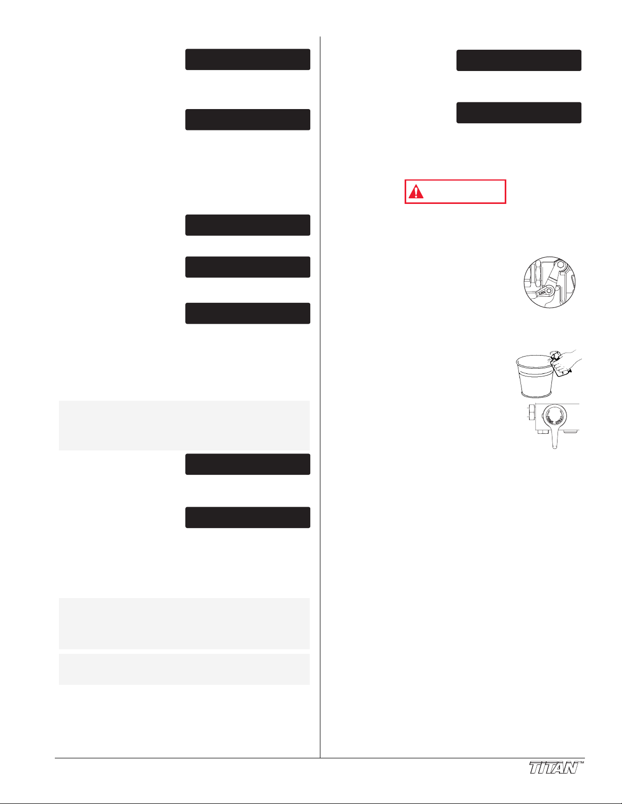
Service Time Screen
ENTER NEW CODE
NUMBER
ENTER OLD CODE
NUMBER
SECURITY CODE
SELECT-4 MENU-1
SET PSI 3000
ACTUAL PSI 2950
PRESSURE
SELECT-4 MENU-1
SERVICE @ XXXHR
RUN HOURS XX
SERVICE TIME
SELECT-4 MENU-1
Trigger lock in
locked position.
WARNING
PULSE CLEAN
ACTUAL PSI XXXX
PRIME
The Service Time screen
allows the user to set a service
time interval (in hours). Below
the set time, the screens shows the current amount of hours
on the sprayer. To select the Service TImer screen, press the
#4 key.
The screen will toggle between
the service hours and a screen
that allows the user to change
the service time interval.
When the service time interval is set and met by the run hours,
the display will toggle between the "Main screen" and a
"Service Required" screen at sprayer startup. To stop the
toggling, scroll to the "Service Time" screen and either set a
new service time interval or set the service time to "0".
Pressure Screen
The Pressure screen allows
the user to see the current set
point pressure as well as the
actual working pressure.
To select the Pressure screen,
press the #4 key. This screen
is also the Main Screen.
Security Code Screen
The Security Code screen
allows the user to set a four
digit security code to prevent
unauthorized use of the sprayer. If a security code has been
set, the control system display will ask for the code at startup.
If the correct code is entered, the display will show the Main
Screen and the sprayer will operate. If the wrong code is
entered, the display will continue to ask for the correct code
and the sprayer will be disabled. To set or change the security
code, press the #2 key.
NOTE: If the sprayer is new, no security code is set
and the Main Screen will appear at startup.
Also, when setting a security code for the first
time, the “Enter Old Code Number” screen will
not appear.
Prime Screen
he Prime screen appears
T
when the pressure control
knob is set at the “Min” setting
in the yellow zone.
Pulse Clean Screen
The Pulse Clean screen
appears when the pressure
control knob is set at the
PULSE CLEAN position in the red zone and the
PRIME/SPRAY valve is in the PRIME position.
Pressure Relief Procedure
Be sure to follow the pressure relief procedure when
shutting the unit down for any purpose, including
servicing or adjusting any part of the spray system,
changing or cleaning spray tips, or preparing for cleanup.
1. Lock the gun by turning the gun trigger
lock to the locked position.
2. Turn off the sprayer by moving the
ON/OFF switch to the OFF position.
3. Turn the pressure control knob
counterclockwise to its OFF position in
the black zone.
4. Unlock the gun by turning the gun trigger
lock to the unlocked position.
5. Hold the metal part of the gun firmly to
the side of a metal container to ground
the gun and avoid a build up of static
electricity.
6. Trigger the gun to remove any pressure
that may still be in the hose.
7. Lock the gun by turning the gun trigger
lock to the locked position.
8. Move the PRIME/SPRAY valve down to
the PRIME position.
Enter the old security code
number to access the screen
that allows the code change.
If the wrong code is entered, the display will continue to ask
for the correct code and the security code cannot be changed.
Enter the new security code.
Once the new code is entered,
the display will automatically
ask that the new code be re-entered for verification. If the
same new code is re-entered, the display will confirm that the
new code has been accepted and return to the Main Screen.
If the new code is re-entered incorrectly, the display will return
to the “Enter New Code Number” screen and the process will
repeat.
NOTE: To remove the security function, enter “1111”
NOTE: If there is no action at any menu screen for 30
at the “Enter New Code Number” screen (this
is the default code that leaves the sprayer
unlocked). As a result, the Main Screen will
appear at sprayer startup.
seconds, the display will go back to the Main
Screen.
© Titan Tool Inc. All rights reserved. 7
Page 8
Spraying
Too Thick
Offspray
Arcing Gun at angle
start
stroke
release
trigger
pull
trigger
end
stroke
WARNING
Good spray pattern
Paint tailing pattern
O
verlap edges
1st 2nd 3rd 4th 5th
POSSIBLE INJECTION HAZARD. Do not spray without the
tip guard in place. Never trigger the gun unless the tip is
in either the spray or the unclog position. Always engage
the gun trigger lock before removing, replacing, or
cleaning tip.
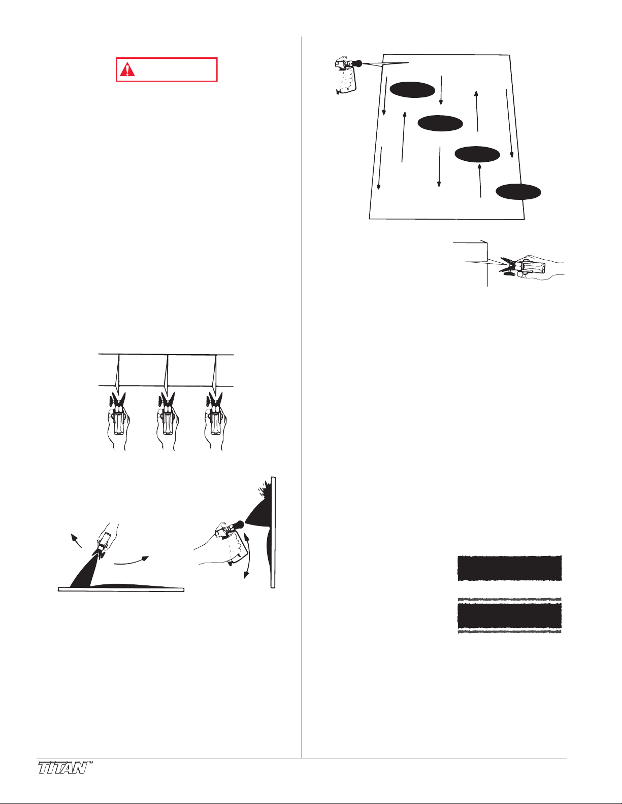
Spraying Technique
The following techniques, if followed, will assure professional
painting results.
Hold the gun perpendicular to the surface and always at equal
distance from the surface. Depending on the type of material,
surface, or desired spray pattern, the gun should be held at a
distance of 12 to 14 inches (30 to 35 cm).
Move the gun either across or up and down the surface at a
steady rate. Moving the gun at a consistent speed conserves
material and provides even coverage. The correct spraying
speed allows a full, wet coat of paint to be applied without
runs or sags.
Holding the gun closer to the surface deposits more paint on
the surface and produces a narrower spray pattern. Holding
the gun farther from the surface produces a thinner coat and
wider spray pattern. If runs, sags, or excessive paint occur,
change to a spray tip with a smaller orifice. If there is an
insufficient amount of paint on the surface or you desire to
spray faster, a larger orifice tip should be selected.
Maintain uniform spray stroke action. Spray alternately from
left to right and right to left. Begin movement of the gun
before the trigger is pulled.
Avoid arcing or holding the gun at an angle. This will result in
an uneven finish.
Proper lapping (overlap of spray pattern) is essential to an
even finish. Lap each stroke. If you are spraying horizontally,
aim at the bottom edge of the preceding stroke, so as to lap
the previous pattern by 50%.
For corners and edges, split the
center of the spray pattern on the
corner or edge and spray vertically
so that both adjoining sections
receive approximately even
amounts of paint.
When spraying with a shield, hold it firmly against the surface.
Angle the spray gun slightly away from the shield and toward
the surface. This will prevent paint from being forced
underneath.
Shrubs next to houses should be tied back and covered with a
canvas cloth. The cloth should be removed as soon as
possible. Titan gun extensions are extremely helpful in these
situations.
Nearby objects such as automobiles, outdoor furniture, etc.
should be moved or covered whenever in the vicinity of a
spray job. Be careful of any other surrounding objects that
could be damaged by overspray.
Practice
1. Be sure that the paint hose is free of kinks and clear of
objects with sharp cutting edges.
2. Set the pressure to minimum by turning the pressure
control knob to the “Min” setting in the yellow zone.
3. Move the PRIME/SPRAY valve up to its SPRAY position.
4. Turn the pressure control knob clockwise to its highest
setting. The paint hose should stiffen as paint begins to
flow through it.
5. Unlock the gun trigger lock.
6. Trigger the spray gun to bleed air out of the hose.
7. When paint reaches the spray tip, spray a test area to
check the spray pattern.
8. Use the lowest pressure
setting necessary to get a
good spray pattern. If the
pressure is set too high, the
spray pattern will be too light.
If the pressure is set too low,
tailing will appear or the paint
will spatter out in gobs rather
than in a fine spray.
8 © Titan Tool Inc. All rights reserved.
Page 9

Cleanup
WARNING
Min PSI
(Bar)
Max PSI
(Bar)
Pulse
Clean
WARNING
CAUTION
WARNING
CAUTION
WARNING
CAUTION
Special cleanup instructions for use with flammable
solvents:
• Always flush spray gun preferably outside and at least one
hose length from spray pump.
• If collecting flushed solvents in a one gallon metal
container, place it into an empty five gallon container, then
flush solvents.
Area must be free of flammable vapors.
•
• Follow all cleanup instructions.
13. Continue to trigger the spray gun into the waste container
until the solvent coming out of the gun is clean.
NOTE: For long-term or cold weather storage, pump
14. Follow the “Pressure Relief Procedure” found in the
15. Unplug the unit and store in a clean, dry area.
o not store the unit under pressure.
D
mineral sprits through the entire system.
For short-term storage when using latex paint,
pump water mixed with Titan Liquid Shield
through the entire system (see the Accessories
section of this manual for part number).
Operation section of this manual.
The sprayer, hose, and gun should be cleaned thoroughly
after daily use. Failure to do so permits material to build
up, seriously affecting the performance of the unit.
Always spray at minimum pressure with the gun nozzle tip
removed when using mineral spirits or any other solvent
to clean the sprayer, hose, or gun. Static electricity
buildup may result in a fire or explosion in the presence of
flammable vapors.
1. Follow the “Pressure Relief Procedure” found in the
Operation section of this manual.
2. Remove the gun tip and tip guard and clean with a brush
using the appropriate solvent.
3. Place the siphon tube into a container of the appropriate
solvent. Examples of the appropriate solvent are water for
latex paint or mineral spirits for oil-based paints.
4. Place the return hose into a metal waste container.
5. Move the PRIME/SPRAY valve down to its
PRIME position.
NOTE: Hold the return hose in the waste
6. Set the pressure to Turbo PulseClean by
7. Turn on the sprayer by moving the
8.
9. Turn off the sprayer by moving the ON/OFF switch to the
10. Move the PRIME/SPRAY valve up to its
1.
1
Ground the gun by holding it against the
edge of the metal container while
flushing. Failure to do so may lead to a
static electric discharge, which may cause
a fire.
12. Trigger the gun into the metal waste
container when moving the
PRIME/SPRAY valve to PRIME in
case the sprayer is pressurized.
turning the pressure control knob to its
PULSE CLEAN position in the red zone.
ON/OFF switch to the ON position.
Allow the solvent to circulate through the unit and flush
the paint out of the return hose into the metal waste
container
OFF position.
SPRAY position.
urn on the sprayer
T
container until the paint is flushed out of the hose and
solvent is coming out of the gun.
.
.
Maintenance
Before proceeding, follow the Pressure Relief Procedure
outlined previously in this manual. Additionally, follow all
other warnings to reduce the risk of an injection injury,
injury from moving parts or electric shock. Always unplug
the sprayer before servicing!
General Repair and Service Notes
The following tools are needed when repairing this sprayer:
Phillips Screwdriver 3/8" Hex Wrench
Needle Nose Pliers 5/16" Hex Wrench
Adjustable Wrench 1/4" Hex Wrench
Rubber Mallet 3/16" Hex Wrench
Flat-blade Screwdriver 5/32” Hex Wrench
1. Before repairing any part of the sprayer, read the
instructions carefully, including all warnings.
Never pull on a wire to disconnect it. Pulling on a wire
could loosen the connector from the wire.
2. Test your repair before regular operation of the sprayer to
be sure that the problem is corrected. If the sprayer does
not operate properly, review the repair procedure to
determine if everything was done correctly. Refer to the
Troubleshooting Charts to help identify other possible
problems.
3. Make certain that the service area is well ventilated in
case solvents are used during cleaning.
protective eyewear while servicing. Additional protective
equipment may be required depending on the type of
cleaning solvent. Always contact the supplier of solvents
for recommendations.
4. If you have any further questions concerning your TITAN
Airless Sprayer, call TITAN:
Customer Service (U.S.) .......................
................................................
Fax
Customer Service (Canada)..................1-800-565-8665
Fax ................................................ 1-905-856-8496
Customer Service (International)...........1-201-405-7520
Fax ................................................1-201-405-7449
Always wear
1-800-526-5362
1-800-528-4826
© Titan Tool Inc. All rights reserved. 9
Page 10
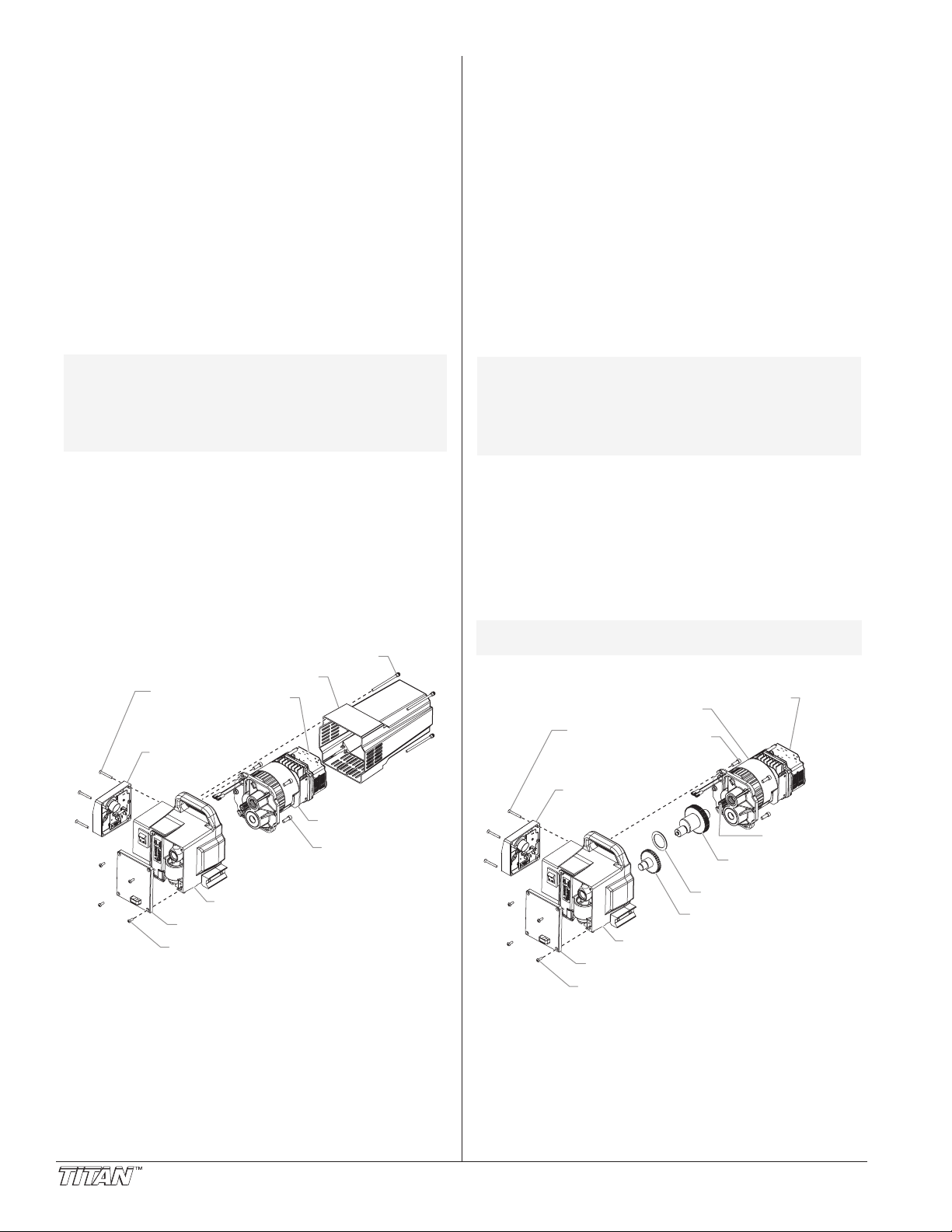
Replacing the Motor
Motor
Motor Mounting
Screw
Pump Housing
Front Cover
Front Cover Screw
Control
Panel
Control
Panel
Mounting
Screw
Motor Cover Screw
Motor Cover
Electronic
Pressure
Control
(EPC)
2nd Stage Gear
Thrust Washer
Gear and Crank
Assembly
Armature Gear
Motor
Electronic
Pressure
Control
(EPC)
Motor
Mounting
Screw
Pump Housing
Front Cover
Front Cover Screw
Control
Panel
Control
Panel
Mounting
Screw
1. Perform the Pressure Relief Procedure and unplug the
sprayer.
2. Loosen and remove the four motor cover screws.
Remove the motor cover.
3. At the electronic pressure control (EPC) on the back off
the motor, disconnect the wire coming from the
potentiometer and the wire coming from the transducer.
Also, disconnect the two wires coming from the control
panel board (refer to the electrical schematic in the Parts
List section of this manual).
. Remove the four control panel mounting screws. Pull
4
ack the control panel for access to the control panel
b
board.
5. At the the control panel board, disconnect the two wires
coming from the motor (refer to the electrical schematic in
the Parts List section of this manual).
6. Loosen and remove the four motor mounting screws.
7. Pull the motor out of the pump housing.
NOTE: If the motor will not dislodge from the pump
8. With the motor removed, inspect the gears in the pump
9. Install the new motor into the pump housing.
10. Secure the motor with the four motor mounting screws.
11. Reconnect the wires (refer to the electrical schematic in
12. Position the control panel on the pump housing and
13. Slide the motor cover over the motor. Secure the motor
housing:
• Remove the front cover plate.
• Using a rubber mallet, carefully tap on the
front of the motor crankshaft that extends
through the slider assembly.
housing for damage or excessive wear. Replace the
gears, if necessary.
the Parts List section of this manual).
secure in position using the four control panel mounting
screws.
cover with the four motor cover screws.
Replacing the Gears
1. Perform the Pressure Relief Procedure and unplug the
sprayer.
2. Loosen and remove the four motor cover screws.
Remove the motor cover.
3. At the electronic pressure control (EPC) on the back off
the motor, disconnect the wire coming from the
potentiometer and the wire coming from the transducer.
Also, disconnect the two wires coming from the control
panel board (refer to the electrical schematic in the Parts
List section of this manual).
4. Remove the four control panel mounting screws. Pull
back the control panel for access to the control panel
board.
. At the the control panel board, disconnect the two wires
5
oming from the motor (refer to the electrical schematic in
c
he Parts List section of this manual).
t
6. Loosen and remove the four motor mounting screws.
7. Pull the motor out of the pump housing.
NOTE: If the motor will not dislodge from the pump
8. Inspect the armature gear on the end of the motor for
9. Remove and inspect the 2nd stage gear for damage or
10. Remove and inspect the gear and crank assembly for
11. Reassemble the pump by reversing the above steps.
NOTE: Refill the gear box in the pump housing with
housing:
• Remove the front cover plate.
• Using a rubber mallet, carefully tap on the
front of the motor crankshaft that extends
through the slider assembly.
damage or excessive wear. If this gear is completely
worn out, replace the entire motor.
excessive wear. Replace if necessary.
damage or excessive wear. Replace if necessary.
During reassembly, make sure the thrust washer is in
place.
five ounces of Lubriplate (P/N 314-171).
10 © Titan Tool Inc. All rights reserved.
Page 11
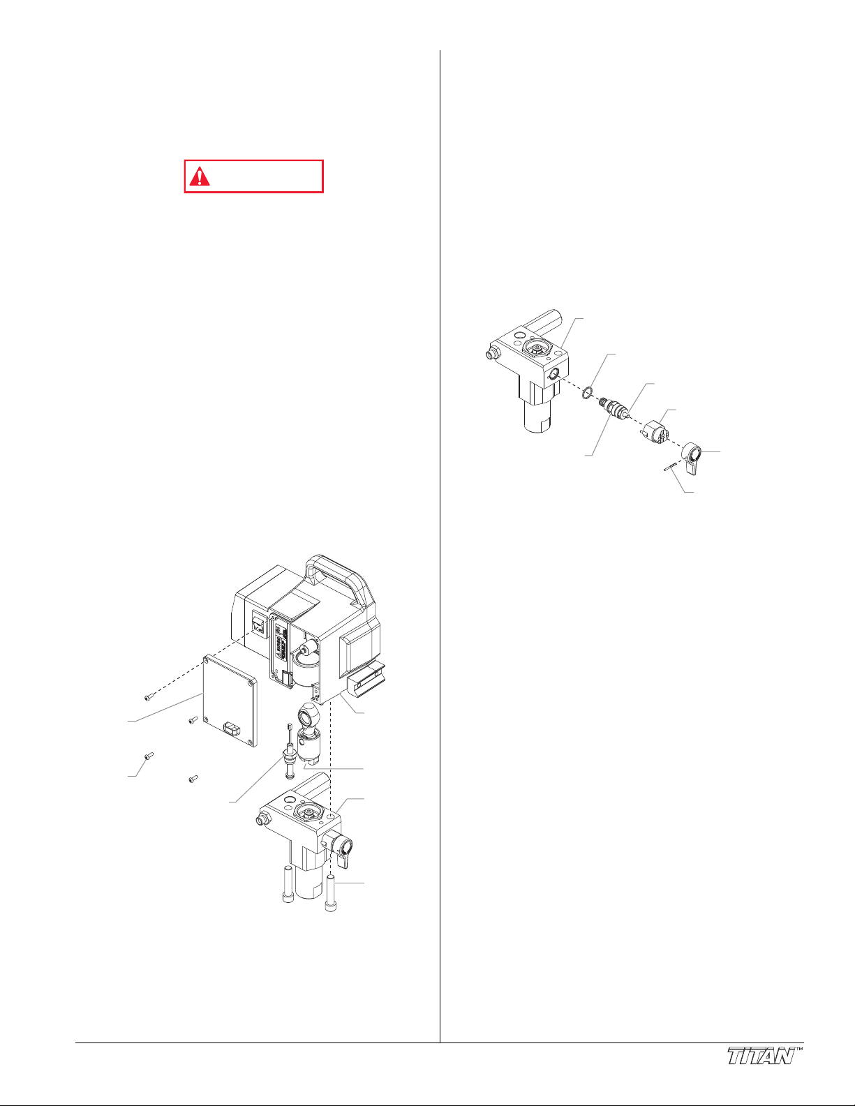
Replacing the Transducer
T-Slot
Pump
Housing
Pump
Block
Pump
Block
Mounting
Screw
Front
Cover
Front
Cover
Screw
Transducer
Assembly
WARNING
Gasket
Cam Base
Valve Stem
Pump Block
Valve Housing
Assembly
Valve
Handle
Groove Pin
1. Loosen and remove the four front cover screws. Remove
the front cover.
2. Stop the sprayer at the bottom of its stroke so that the
piston is in its lowest position.
3. Perform the Pressure Relief Procedure and unplug the
sprayer.
Before proceeding, follow the Pressure Relief Procedure
outlined previously in this manual. Additionally, follow all
other warnings to reduce the risk of an injection injury,
injury from moving parts or electric shock. Always unplug
the sprayer before servicing!
4. Tilt the pump back for easy access to the fluid section.
5. Using a 3/8” hex wrench, loosen and remove the two
pump block mounting screws.
6. Pull the pump block down approximately 1/2” from the
pump housing to clear the transducer.
7. Slide the pump block and piston rod forward until the
piston rod is out of the T-slot on the slider assembly.
8. Carefully pull the transducer wire out of the pump housing
until the connection to the transducer jumper is exposed.
Unplug the wire from the transducer jumper (refer to the
electrical schematic in the Parts List section of this
manual).
9. Using a wrench, remove the transducer assembly from the
pump block.
10. Thread the new transducer assembly into the pump block.
Tighten securely with a wrench.
11. Plug the new transducer wire into the transducer jumper
(refer to the electrical schematic in the Parts List section of
this manual).
12. Reassemble the pump by reversing steps 1–7.
Replacing the PRIME/SPRAY Valve
Perform the following procedure using PRIME/SPRAY valve
replacement kit P/N 700-258
1. Push the groove pin out of the valve handle.
2. Remove the valve handle and the cam base.
. Using a wrench, loosen and remove the valve housing
3
ssembly.
a
4. Make sure the gasket is in place and thread the new valve
housing assembly into the pump block. Tighten securely
with wrench.
5. Place the cam base over the valve housing assembly.
Lubricate the cam base with grease and line up the cam
with the pump block.
. Line up the hole on the valve stem with the hole in the
6
alve handle.
v
7. Insert the groove pin into the valve handle and through
the valve stem to secure the valve handle in position.
© Titan Tool Inc. All rights reserved. 11
Page 12
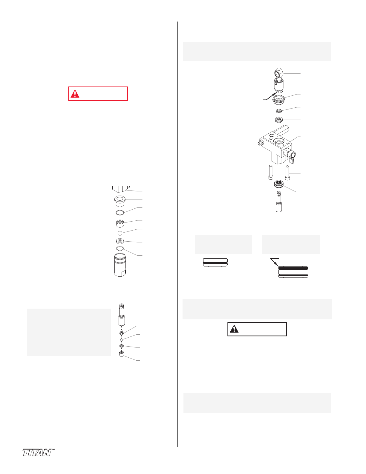
Servicing the Fluid Section
Outlet Valve
Retainer
Outlet Valve
Seat
Outlet Valve
Ball
Outlet Cage
Piston Rod
Foot Valve
Housing
Foot Valve
Seat
Foot Valve
Ball
Bushing
Teflon
O-Ring
Inlet Cage
Foot Valve
Seal
Pump Block
WARNING
CAUTION
Install upper packing
with raised lip and O-ring
facing down.
O-Ring
Raised Lip
Beveled Edge
Install lower packing
with the beveled
edge facing up.
Slider
A
ssembly
Retainer
Nut
Piston
Guide
Upper
Packing
Pump
Block
Lower
Packing
Pump Block
Mounting
Screw
Piston Rod
T-Slot
Use the following procedures to service the valves and repack
the fluid section. Perform the following steps before
performing any maintenance on the fluid section.
1. Loosen and remove the four front cover screws. Remove
the front cover.
. Stop the sprayer at the bottom of its stroke so that the
2
iston is in its lowest position.
p
3. Perform the Pressure Relief Procedure and unplug the
sprayer.
efore proceeding, follow the Pressure Relief Procedure
B
utlined previously in this manual. Additionally, follow all
o
ther warnings to reduce the risk of an injection injury,
o
njury from moving parts or electric shock. Always
i
unplug the sprayer before servicing!
4. For High Rider cart units, remove the return hose from the
hose clip on the siphon tube. Unscrew the siphon tube
from the foot valve housing.
5. For Skid units, unscrew the return hose assembly from
the pump block. Remove the retaining clip from the
bottom of the foot valve housing. Remove the siphon
assembly.
6. Tilt the sprayer back for easy access to the fluid section.
Servicing the Valves
The design of the fluid section
allows access to the foot valve and
seat as well as the outlet valve and
seat without completely
disassembling the fluid section. It
is possible that the valves may not
seat properly because of debris
stuck in the foot valve seat or outlet
valve seat. Use the following
instructions to clean the valves and
reverse or replace the seats.
1. Using a wrench, loosen and
remove the foot valve housing
from the pump block.
2. Clean out any debris in the
foot valve housing and
examine the valve housing and
seat. If the seat is damaged, reverse or replace the seat.
3. Using a 3/8" hex wrench, loosen and remove the outlet
valve retainer from the piston rod.
NOTE: Always service the
Clean out any debris and
4.
examine the outlet valve housing
and seat. If the seat is damaged,
reverse or replace the seat.
5. Remove, clean, and inspect the outlet cage and outlet
valve ball. Replace if they are worn or damaged.
Reassemble the valves by reversing the steps above.
6.
outlet valve with the
piston rod attached to
the pump. This will
prevent the piston rod
from rotating during
disassembly of the
outlet valve.
R
epacking the Fluid Section
1. Remove the foot valve assembly using the steps in the
“Servicing the Valves” procedure above.
OTE: The outlet valve does not need to be
N
2. Using 3/8” a hex
. Pull the pump block
3
4. Slide the pump block
5. Slide the piston rod
6.
7. Remove the upper
8. Clean the pump block
9. Inspect the piston rod for wear and replace if necessary.
10. Reassemble the outlet valve assembly into the piston rod.
NOTE: Use the T-slot on the slider assembly to hold
Never use a wrench on the piston itself. This could cause
damage to the piston and cause leakage.
1
1. Insert the piston guide into the retainer nut. Thread the
12. Slide the piston guide tool (included in the repacking kit)
NOTE: Coat the piston guide tool and the piston rod
13. Using a wrench, tighten the retainer nut securely.
14. Slide the top of the piston rod into the T-slot on the slider
12 © Titan Tool Inc. All rights reserved.
isassembled from the piston rod for this
d
rocedure.
p
wrench, loosen and
remove the two pump
block mounting
screws.
own approximately
d
/2” from the pump
1
ousing.
h
nd piston rod
a
forward until the
piston rod is out of
the T-slot on the
slider assembly.
out through the
bottom of the pump
block
Loosen and remove
the retainer nut and
piston guide from the
pump block.
and lower packings
from the pump block.
and install the new upper and lower packings. Refer to
the illustration below for proper packing orientation.
Tighten the outlet valve retainer with a wrench until secure.
the piston rod in position while securing the
outlet valve retainer.
retainer nut into the pump block until it is hand tight.
over the top of the piston rod and insert the piston rod
through the bottom of the pump block. Using a rubber
mallet, tap the bottom of the piston rod lightly until the
piston rod is in position in the pump block.
with grease before inserting them into the
pump block.
assembly.
Page 13
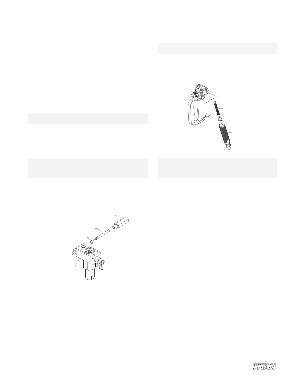
15. Position the pump block underneath the pump housing
Pump Block
Seal
Filter
Filter Housing
Handle
Handle
Seal
Filter
Gun
Body
and push up until it rests against the pump housing.
6. Thread the pump block mounting screws through the
1
ump block and into the pump housing. Tighten securely.
p
17. Reassemble the foot valve assembly into the pump block.
18. For High Rider cart units, thread the siphon tube into the foot
valve and tighten securely. Make sure to wrap the threads
on the siphon tube with Teflon tape before assembly.
Replace the return hose into the hose clip on the siphon
tube.
19. For Skid units, insert the elbow on the siphon assembly
into the bottom of the foot valve housing. Push the
retaining clip up into the groove inside the foot valve
housing to secure the siphon assembly in position.
Thread the return hose into the pump block and tighten
securely.
20. Place the front cover on the pump housing and secure in
position using the four front cover screws.
21. Turn on the sprayer by following the procedure in the
“Operation” section of this manual and check for leaks.
NOTE: Repacking kit P/N 704-586 is available. For
best results use all parts supplied in this kit.
Replacing the Filters
Pump Filter
1. Loosen and remove the filter housing.
2. Turning clockwise, unscrew the filter from the pump block.
NOTE: Left-handed threads require turning the filter
3. Inspect the seal. Based on inspection, clean or replace
4. Turning counterclockwise, thread the new or cleaned filter
5. Slide the filter housing over the filter and thread it into the
clockwise to remove. If the filter breaks off in
the pump block, use a small wood screw to
remove.
the seal.
into the pump block.
pump block until secure.
G
un Filter
1. Move the gun trigger lock to the unlocked position.
. Loosen and remove the handle from the gun body.
2
3. Turning clockwise, unscrew the filter from the gun body.
NOTE: Left-handed threads require turning the filter
4. Turning counterclockwise, screw the new or cleaned filter
5. Make sure the handle seal is in position and thread the
6. Move the gun trigger lock to the locked position.
NOTE: For more detail, part number information, and
clockwise to remove.
into the gun body.
handle into the gun body until secure.
complete assembly drawings, please see the
II
LX-80
Manual (P/N 313-2293).
Professional Airless Gun Owner's
© Titan Tool Inc. All rights reserved. 13
Page 14

P
roblem
he unit will not run.
T
Troubleshooting
C
ause
. The unit is not plugged in.
1
2. Tripped breaker.
3. The pressure is set too low (pressure
control knob set at minimum setting
does not supply power to unit).
4. Faulty or loose wiring.
5. Excessive motor temperature.
. ON/OFF switch is defective.
6
S
olution
. Plug the unit in.
1
2. Reset the breaker.
3. Turn the pressure control knob clockwise to
supply power to the unit and increase the
pressure setting.
4. Inspect or take to a Titan authorized service
center.
5. Allow motor to cool.
. Replace the ON/OFF switch.
6
The unit will not prime.
The unit will not build or
maintain pressure.
1. The PRIME/SPRAY valve is in the
SPRAY position.
2. Air leak in the siphon tube/suction set.
3. The pump filter and/or inlet screen is
clogged.
4. The siphon tube/suction set is clogged.
1. The spray tip is worn.
2. The spray tip is too large.
3. The pressure control knob is not set
properly.
4. The pump filter, gun filter, or inlet
screen is clogged.
5. Material flows from the return hose
when the PRIME/SPRAY valve is in the
SPRAY position.
6. Air leak in the siphon tube/suction set.
7. There is external fluid leak.
8. There is an internal fluid section leak
(packings are worn and/or dirty, valve
balls are worn).
9. Worn valve seats
10. Motor powers but fails to rotate
1. Rotate the PRIME/SPRAY valve clockwise
to the PRIME position.
2. Check the siphon tube/suction set
connection and tighten or re-tape the
connection with Teflon tape.
3. Remove the pump filter element and clean.
Remove the inlet screen and clean.
4. Remove the siphon tube/suction set and
clean.
1. Replace the spray tip following the
instructions that came with the spray gun.
2. Replace the spray tip with a tip that has a
smaller orifice following the instructions that
came with the spray gun.
3. Turn the pressure control knob clockwise to
increase the pressure setting.
4. Remove the pump filter element and clean.
Remove the gun filter and clean. Remove
the inlet screen and clean.
5. Clean or replace the PRIME/SPRAY valve.
6. Check the siphon tube/suction set
connection and tighten or re-tape the
connection with Teflon tape.
7. Check for external leaks at all connections.
Tighten connections, if necessary.
8. Clean the valves and service the fluid
section following the “Servicing the Fluid
Section” procedure in the Maintenance
section of this manual.
9. Reverse or replace the valve seats
following the “Servicing the Fluid Section”
procedure in the Maintenance section of
this manual.
10. Take unit to a Titan authorized service
center.
Fluid leakage at the upper end
of the fluid section.
Excessive surge at the spray
gun.
1. The upper packing is worn.
2. The piston rod is worn.
1. Wrong type of airless spray hose.
2. The spray tip worn or too large.
3. Excessive pressure.
14 © Titan Tool Inc. All rights reserved.
1. Repack the pump following the “Servicing
the Fluid Section” procedure in the
Maintenance section of this manual.
2. Replace the piston rod following the
“Servicing the Fluid Section” procedure in
the Maintenance section of this manual.
1. Replace hose with a minimum of 50’ of 1/4”
grounded textile braid airless paint spray
hose.
2. Replace the spray tip following the
instructions that came with the spray gun.
3. Rotate the pressure control knob
counterclockwise to decrease spray
pressure.
Page 15

P
HIGH MOTOR
TEMPERATURE
LOW VOLTAGE
CHECK MOTOR
CHECK TRANSDUCER
CHECK PAINT
WARNING
COMMUNICATION
ERROR
EXCEEDED
PRESSURE LIMIT
HIGH LOAD
CHECK MECHANISM
HIGH CONTROL
TEMPERATURE
roblem
oor spray pattern.
P
Troubleshooting
C
ause
. The spray tip is too large for the
1
material being used.
2. Incorrect pressure setting.
3. Insufficient fluid delivery.
4. The material being sprayed is too
viscous.
S
olution
. Replace the spray tip with a new or smaller
1
spray tip following the instructions that
came with the spray gun.
2. Rotate the pressure control knob to adjust
the pressure for a proper spray pattern.
3. Clean all screens and filters.
4. Add solvent to the material according to the
manufacturer's recommendations.
he unit lacks power.
T
. The pressure adjustment is too low.
1
2. Improper voltage supply.
Xact Digital Control System Error Messages
The following error message screens appear whenever the
Xact Digital Control System detects a problem with the
. Once a problem occurs and the error message
sprayer
appears, the sprayer will shut down.
Before proceeding, follow the Pressure Relief Procedure
outlined previously in this manual. Additionally, follow all
other warnings to reduce the risk of an injection injury,
injury from moving parts or electric shock. Always
unplug the sprayer before servicing!
Check Paint Screen
The Check Paint screen
appears when the pump
pressure drops to a very low
level and the pressure control knob has not been adjusted.
Check the paint level and refill. Restart the sprayer by
following the “Painting” procedure in the Operation section of
this manual.
Check Transducer Screen
The Check Transducer screen
appears when the transducer
has become disconnected or
is defective. Take the sprayer to a Titan authorized service
center for repair.
Check Motor Screen
The Check Motor screen
appears when the motor or
motor sensor is defective.
Take the sprayer to a Titan authorized service center for repair.
Low Voltage Screen
The Low Voltage screen
appears when the sprayer
shuts down because of low
input voltage. Check the power supply and correct the
problem. Restart the sprayer by following the “Painting”
procedure in the Operation section of this manual.
High Motor Temperature Screen
The High Motor Temperature
screen appears when the
temperature of the motor has
risen too high. Take the sprayer to a Titan authorized service
center for repair.
. Rotate the pressure control knob clockwise
1
to increase the pressure setting.
2. Reconnect the input voltage for 120V AC.
High Control Temperature Screen
The High Control Temperature
screen appears when the
temperature of the Xact Digital
Control System has risen too high. Take the sprayer to a Titan
authorized service center for repair.
High Load Check Mechanism Screen
The High Load Check
Mechanism screen appears
when the sprayer shuts down
because of high current or when the sprayer goes into current
fold back mode.. Take the sprayer to a Titan authorized
service center for repair.
Exceeded Pressure Limit Screen
The Exceeded Pressure Limit
screen appears when the
sprayer pressure exceeds
3300 PSI / 22.8 MPa. Take the sprayer to a Titan authorized
service center for repair.
Communication Error Screen
The Communication Error
screen appears when the Xact
Digital Control System loses
communication with the control panel. Take the sprayer to a
Titan authorized service center for repair.
© Titan Tool Inc. All rights reserved. 15
Page 16
Consignes de sécurité
AVERTISSEMENT
ATTENTION
AVERTISSEMENT
Le présent manuel comprend des renseignements devant être
lus attentivement avant toute utilisation de l'appareil. Lorsque
l'un des symboles suivants apparaît, il est recommandé d'être
particulièrement attentif et de tenir compte des mesures de
sécurité indiquées.
Ce symbole indique un danger potentiel pouvant causer des
blessures graves ou même mortelles. Des renseignements
importants sur la sécurité sont également indiqués.
Ce symbole indique un danger potentiel pouvant causer des
blessures corporelles ou des dommages à l'équipement. Des
renseignements importants sur la façon de prévenir tout
dommage à l'équipement ou toute blessure corporelle mineure
sont également indiqués.
NOTA : Les remarques donnent des renseignements
DANGER: BLESSURES PAR PERFORATION - Le jet de
NE PAS TRAITER UNE BLESSURE PAR PERFORATION
COMME UNE SIMPLE COUPURE! Une perforation peut
entraîner des risques d'amputation. Consultez
immédiatement un médecin.
Pression de service maximale du fluide dans l’appareil :
3300 lb/po2 / 22.8 MPa.
MESURES PRÉVENTIVES:
importants requérant une attention particulière.
peinture à haute pression produit par cet
appareil peut perforer la peau et les tissus
sous-jacents et entraîner de sévères blessures
pouvant nécessiter une amputation. Consultez
immédiatement un médecin.
• NE JAMAIS diriger le pistolet vers une quelconque partie
du corps.
• NE JAMAIS mettre une quelconque partie du corps en
contact avec le jet de liquide. NE JAMAIS se mettre au
contact d'un jet de liquide provenant d'une fuite du flexible
d'alimentation en liquide.
• NE JAMAIS placer votre main devant le pistolet. Des
gants ne vous protégeront pas contre les risques de
blessures par perforation.
• TOUJOURS verrouiller la gâchette du pistolet, fermer la
pompe à liquide et décompresser l'appareil lorsque vous
travaillez sur celui-ci, nettoyez le protecteur de tête,
remplacez la tête de pulvérisation ou vous éloignez de
l'appareil. Couper le moteur ne décompresse pas l'appareil.
Vous devez, pour le décompresser, placer le bouton
AMORÇAGE/PULVÉRISATION en position AMORÇAGE.
Reportez-vous, pour cela, à la PROCÉDURE DE
DÉCOMPRESSION décrite dans de ce manuel.
OUJOURS s'assurer que le protecteur de tête est en
T
•
place lorsque vous pulvérisez. Le protecteur de tête of
une certaine protection contre les blessures par perforation
mais sa principale fonction est d'ordre préventif.
• TOUJOURS ôter la tête de pulvérisation avant de purger
ou nettoyer l'appareil.
Le flexible d'alimentation en peinture peut fuir à la suite
•
d'une usure, de chocs ou de mauvais traitements. Une
fuite peut entraîner une perforation de la peau. Inspecter
le flexible avant chaque utilisation.
• NE JAMAIS utiliser un pistolet dont la gâchette n'est pas
munie d'un loquet ou un cran de sécurité qui soit en état
de fonctionner.
ous les accessoires doivent être homologués pour une
T
•
pression égale ou supérieure à 3300 lb/po2 / 22.8 MPa.
Cela s'applique, entre autres, aux têtes de pulvérisation,
aux accessoires du pistolet et aux flexibles.
fre
Français
AVERTISSEMENT AUX MÉDECINS : Une perforation
sous-cutanée constitue un traumatisme. Il est
important de traiter la blessure de façon chirurgicale
aussitôt que possible. NE RETARDEZ PAS ce
traitement pour des recherches de toxicité. La toxicité
n'est un risque que dans les cas où certains produits
de revêtement pénètrent dans le flux sanguin. Il peut
être nécessaire de faire appel à des soins de chirurgie
plastique ou de reconstruction de la main.
ANGER: RISQUES D'EXPLOSION OU D'INCENDIE - Les
D
MESURES PRÉVENTIVES:
• Veiller à éviter toute accumulation de vapeurs
inflammables en vous assurant que la zone où la
pulvérisation a lieu est suffisamment ventilée.
• Veiller à éviter la présence de toute source incandescente
telle qu'étincelle électrostatique, flamme nue, flammepilote, objet brûlant, cigarette et étincelle provenant du
branchement ou du débranchement d'un cordon
d'alimentation électrique ou d'un commutateur.
• Ne pas fumer dans la zone d’épandage.
• Toujours avoir un extincteur en état de fonctionner à
portée de la main.
• Placer la pompe à peinture à une distance d’au moins un
mètre (3 pi) (on recommande d’ailleurs une plus grande
distance) de l’objet qui doit être vaporisé dans une pièce
séparée bien aérée, ou à une distance d’au moins six
mètres (20 pi) de celui-ci dans une zone bien aérée
(utiliser d’autres tuyaux si nécessaires). Les vapeurs
inflammables sont souvent plus lourdes que l’air. Le
plancher doit être extrêmement bien aéré. La pompe à
peinture contient des pièces pouvant créer des étincelles
et enflammer les vapeurs présentes dans l’air.
• Le matériel utilisé, ainsi que les objets se trouvant à
proximité de la zone de pulvérisation, doivent être
convenablement reliés à la terre afin d'éviter toute
étincelle ou toute décharge électrostatique.
• N'utiliser que des flexibles d'alimentation en liquide à
haute pression conducteurs ou reliés à la terre dans les
cas d'utilisation sans air comprimé. S'assurer que le
pistolet est convenablement relié à la terre par
l'intermédiaire du flexible.
• Le cordon d’alimentation doit être raccordé à un circuit
mis à la terre.
• Toujours purger l’appareil dans un contenant métallique
séparé, en s’assurant que la pompe soit à basse pression
et que le chapeau soit retiré. T
contre la paroi du contenant pour mettre celui-ci à la terre
et empêcher l’émission d’étincelles causées par
l’électricité statique.
• Se conformer aux consignes et recommandations de
sécurité du fabricant du solvant ou du produit.
S’entourer de toutes les précautions possibles lorsqu’on
•
utilise des produits ayant un point d’éclair inférieur à 21
C (70
°
à laquelle les vapeurs émanant du fluide peuvent
s’enflammer au contact d’une flamme ou d’une étincelle.
• Le plastique peut être une source d’étincelles provoquées
par l’électricité statique. Ne jamais utiliser une couverture
en plastique pour fermer une zone d’épandage ni utiliser
des toiles de protection en plastique lors de la
pulvérisation de matières inflammables.
Lorsque vous purgez l'appareil, veillez à utiliser à la
•
pression minimale.
16 © Titan Tool Inc. Tous droits réservés.
apeurs dégagées par le solvant ou la peinture
v
ont explosives et inflammables et peuvent
s
auser des corporels sérieux ou dommages
c
atériels.
m
enir le pistolet fermement
°F). Le point d’éclair d’un fluide est la température
Page 17
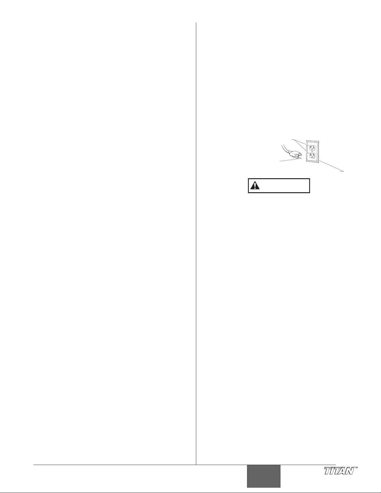
MOTEUR À ESSENCE
ATTENTION
Prise de terre
Goupille de mise à la terre
Couvercle du boîtier de prise de terre
(DANS LES CAS OÙ CELA S’APPLIQUE)
Toujours placer la pompe à l’extérieur de la structure à l’air
frais. Garder tous les solvants loin de l’échappement du
moteur. Ne jamais remplir le réservoir à carburant lorsque le
moteur est en marche ou lorsqu’il est chaud ; les surfaces
chaudes risquent d’enflammer le carburant déversé
accidentellement. Toujours raccorder un fil de mise à la terre
entre la pompe et un objet mis à la terre, tel qu’une conduite
d’eau métallique. Se reporter au guide d’utilisation du moteur
pour obtenir de plus amples renseignements concernant la
sécurité.
DANGER: RISQUES D'EXPLOSION PAR INCOMPATIBILITÉ
ESURES PRÉVENTIVES:
M
• Ne pas utiliser de matériaux contenant des agents de
• Ne pas utiliser des solvants à base d’hydrocarbure
• Communiquer avec votre fournisseur de revêtement pour
DANGER: VAPEURS NOCIVES – la peinture, les solvants,
MESURES PRÉVENTIVES:
• Utiliser un respirateur ou un masque chaque fois qu'il y a
• Porter des lunettes de protection.
• Porter des vêtements de protection, conformément aux
DANGER: GÉNÉRALITÉS - Peut causer des dommages
MESURES PRÉVENTIVES:
• Avant d'utiliser tout équipement, lire attentivement toutes
• Toujours débrancher le moteur de l’alimentation électrique
• Se conformer à la législation locale, provinciale ou fédérale
• Les normes de sécurité du Gouvernement américain sont
• N’utiliser que les pièces autorisées par le fabricant.
• Vérifier, avant toute utilisation, que les flexibles ne
• Tout flexible, raccord orientable, pistolet et accessoire
• Ne jamais pulvériser lorsqu'il vente.
• Porter des vêtements pour protéger la peau et les
DES MATÉRIAUX - Peuvent être à l'origine de
corporels sérieux ou dommages matériels.
blanchiment ou du chlore.
halogéné tels que l’agent anticryptogamique, le chlorure
de méthylène et le trichloro-éthane-1,1,1. Ces produits ne
sont pas compatibles avec l’aluminium
connaître la compatibilité du matériau avec l’aluminium.
les insecticides et autres matériaux peuvent
être nocifs lorsqu’ils sont inhalés ou en contact
avec le corps. Les vapeurs peuvent causer une
nausée importante, des évanouissements ou
un empoisonnement.
des risques d'inhalation de vapeurs. Lire attentivement
toutes les instructions se rapportant au masque pour
vérifier que celui-ci vous assure une protection suffisante
contre les vapeurs toxiques.
directives du fabricant de revêtement.
matériels ou corporels sérieux.
les instructions et les consignes de sécurité
avant d’effectuer des travaux sur l’appareil.
pour tout ce qui concerne la ventilation, la prévention des
incendies et les conditions générales d'utilisation.
régies par le Occupational Safety and Health Act (OSHA).
Il est important de consulter ces normes, en particulier la
section 1910 sur le normes générales et la section 1926
sur les des normes de la construction.
L’utilisateur assume tous les risques et responsabilités
lorsqu’il utilise des pièces qui ne sont pas conformes aux
caractéristiques techniques minimales ainsi qu’aux
dispositifs de sécurité du fabricant de la pompe.
présentent pas d'entaille ou de fuite, que le couvercle ne
soit pas gonflé et que les raccords ne soient pas
endommagés. Si le flexible a subi l'un des dommages
précités, remplacez-le immédiatement. Ne jamais réparer
un flexible d'alimentation en peinture. Le remplacer par un
autre flexible mis à la terre.
utilisé avec cet appareil doit pouvoir fonctionner à une
pression égale ou supérieure à 3300 lb/po2 / 22.8 MPa.
cheveux contre tout contact avec la peinture.
Instructions de mise à la terre
Cet appareil doit être mis à la terre. La mise à la terre réduit
les risques d'électrocution lors d'un court-circuit en permettant
au courant de s'écouler par le fil de mise à la terre. Cet
appareil est muni d'un cordon électrique avec fil de mise à la
terre ainsi que d'une fiche de terre. La fiche doit être branchée
sur une prise installée correctement et mise à la terre
conformément à la réglementation et aux codes en vigueur.
DANGER — Une prise de terre mal branchée peut être à l'origine
d'électrocutions. S'il s'avère nécessaire de réparer ou de remplacer
le cordon électrique ou la fiche, ne pas brancher le fil vert de mise à
la terre sur l'une ou l'autre des bornes à broche plate. Le fil
recouvert d'un isolant vert avec ou sans rayures jaunes est le fil de
mise à la terre et doit être branché sur la broche de mise à la terre.
i vous ne comprenez pas les instructions de mise à la terre
S
u si vous n'êtes pas sûr que l'appareil est correctement mis à
o
a terre, contactez un électricien agréé. Ne pas modifier la
l
iche d'origine. Si la prise ne convient pas à la fiche, faites
f
nstaller la prise adéquate par un électricien agréé.
i
Utiliser uniquement une rallonge à trois fils munie d'une fiche
de terre dans une prise secteur mise à la terre correspondant
au type de fiche de l'appareil. S'assurer que votre rallonge est
en bon état. Lorsque vous utilisez une rallonge, assurez-vous
qu'elle soit d'un calibre suffisant pour supporter l'intensité du
courant requise par l'appareil. Une rallonge trop mince
entraîne une chute de tension, une diminution de l'intensité et
une surchauffe. Une rallonge de calibre 12 est recommandée.
Si vous devez utiliser une rallonge à l’extérieur, celle-ci doit
comprendre la marque W-A après la désignation indiquant le
type de cordon. Par exemple, la désignation SJTW-A indique
que le cordon est conçu pour être utilisé à l’extérieur.
© Titan Tool Inc. Tous droits réservés. 17
Français
Page 18
Precauciones de seguridad
ADVERTENCIA
PRECAUCION
ADVERTENCIA
Este manual contiene información que debe leer y comprender
antes de usar el equipo. Cuando se encuentre con uno de los
siguientes símbolos, asegúrese de observar sus indicaciones
de seguridad.
NOTA PARA EL MÉDICO: La inyección dentro de la piel
s una lesión traumática. Es importante que la lesión
e
se trate quirúrgicamente tan pronto como sea posible .
NO retrase el tratamiento por investigar la toxicidad.
La toxicidad es motivo de preocupación con algunos
revestimientos que se inyectan directamente en la
corriente sanguínea. Es recomendable consultar a un
cirujano plástico o reconstructor de manos.
Este símbolo indica la existencia de un peligro potencial que
puede causar lesiones graves o la muerte. Después del
mismo se incluye información de seguridad importante.
Este símbolo indica la existencia de un peligro potencial para
usted o el equipo. Después del mismo se incluye información
importante que indica la forma de evitar daños al equipo o la
forma de prevenir lesiones menores.
NOTA: los avisos contienen información importante,
présteles especial atención.
PELIGRO: LESIÓN POR INYECCIÓN - La corriente de
pintura de alta presión que produce este
equipo puede perforar la piel y tejidos
subyacentes, lo que conduciría a lesiones
serias y una posible amputación. Consulte de
inmediato a un médico.
NO TRATE LAS LESIONES POR INYECCIÓN COMO SI
FUERAN SIMPLES CORTADAS! Una inyección puede
conducir a una amputación. Consulte de inmediato a un
médico.
El rango de operación máximo de la unidad es 3300 PSI /
22.8 MPa de presión de fluidos.
PARA PREVENIR:
• NO dirija NUNCA la punta de la pistola hacia alguna parte
del cuerpo.
• NO permita NUNCA que alguna parte del cuerpo tenga
contacto con la corriente del fluido. EVITE tener contacto
con corrientes de fluido que salgan de fugas que haya en
la manguera.
• NO ponga NUNCA la mano enfrente de la manguera. Los
guantes no ofrecen ninguna protección contra lesiones
por inyección.
• Bloquee SIEMPRE el gatillo de la pistola, apague la
bomba de fluido y libere toda la presión antes de dar
mantenimiento, limpiar el protector de la boquilla, cambiar
la boquilla o dejar desatendido el equipo. La presión no
se liberará al apagar el motor. Para liberar la presión
debe girarse la perilla PRIME/SPRAY (cebar/atomizar)
hasta la posición PRIME. Consulte el PROCEDIMIENTO
PARA LIBERAR LA PRESIÓN que se describe en este
manual.
• Mantenga puesto SIEMPRE el protector de la boquilla
mientras atomice. El protector de la boquilla ofrece cierta
protección contra lesiones por inyección pero es
principalmente un dispositivo de advertencia.
• Quite SIEMPRE la boquilla del atomizador antes de
enjuagar o limpiar el sistema.
• Pueden desarrollarse fugas en la manguera de pintura
por causa del desgaste, retorcimientos o el abuso. Una
fuga es capaz de inyectar el material en la piel. Cada vez
que use la manguera de pintura, inspecciónela antes.
• NO use nunca una pistola de atomización que no tenga
un bloqueador o un protector de gatillo puesto y que
funcione.
• Todos los accesorios deben tener una capacidad de 3300
lb/pulg2 / 22.8 MPa o mayor. Esto incluye las boquillas
de atomizador, pistolas, extensiones y mangueras.
PELIGRO: EXPLOSIÓN O INCENDIO - Los vapores de
PARA PREVENIR:
• Debe proveerse un escape y aire fresco para hacer que el
•
• No fume en la zona de trabajo.
• Debe haber un equipo para extinguir incendios
• Coloque la bomba para pintar a un mínimo de 1 m (de
• El equipo que se utilice, así como los objetos que estén
• Use solamente mangueras para fluidos de alta presión,
• El cable de alimentación debe enchufarse a un circuito
• Siempre enjuague la unidad en un recipiente de metal por
• Siga las advertencias y avisos de seguridad del fabricante
• Tenga muchísimo cuidado al usar materiales cuyo punto
• El plástico puede causar chispas estáticas. Nunca
• Cuando enjuague el equipo utilice la presión más baja
MOTOR DE GAS (SEGÚN CORRESPONDA)
Coloque siempre la bomba fuera del edificio, al aire libre.
Mantenga todo solvente alejado del escape del motor. Nunca
llene el tanque de combustible si el motor está encendido o
caliente. La superficie caliente puede encender el combustible
derramado. Conecte siempre un conductor de tierra desde la
unidad de la bomba a un objeto puesto a tierra, por ejemplo
una tubería de agua metálica. Consulte el manual del motor
para obtener información completa de seguridad.
solventes y pintura pueden explotar o
incendiarse, causando con esto lesiones
severas y/o daños en la propiedad.
aire que está dentro del área de atomización se mantenga
libre de acumulaciones de vapores inflamables.
Evite todas las fuentes de ignición como son las chispas
electrostáticas, llamas abiertas, flamas de piloto, objetos
calientes, cigarros, y chispas que se generan al conectar
y desconectar las extensiones o de apagadores de luz
que estén funcionando.
permanentemente y en buenas condiciones.
preferencia más) en una habitación aparte, bien ventilada,
alejada del objeto que va a pintar o a por lo menos 6 m
de dicho objeto, en una zona bien ventilada (utilice una
manguera más larga, si es necesario). Los gases
inflamables a menudo son más pesados que el aire. La
zona del piso debe tener la debida ventilación. La bomba
para pintar contiene piezas que forman arcos que emiten
chispas y pueden encender los gases.
dentro y alrededor del área de atomización, deben
conectarse a tierra de manera apropiada para prevenir las
descargas eléctricas y las chispas.
conductoras o conectadas a tierra, para aplicaciones sin
aire. Asegúrese de que la pistola esté conectada a tierra
de manera apropiada, mediante conexiones de
manguera.
aterrado.
separado, con presión baja en la bomba y sin la boquilla.
Sostenga la pistola firmemente contra el recipiente para
ponerlo a tierra y evitar chispas estáticas.
de los materiales y solventes.
de ignición sea inferior a 70° F (21° C). El punto de
ignición es la temperatura a la cual pueden encenderse
los vapores emanados por un fluido al exponerlos a
llamas o chispas.
cuelgue plástico en las ventanas ni en las puertas del
área donde va a pintar. No utilice plástico para proteger
el piso cuando pinte materiales inflamables.
posible.
Español
18 © Titan Tool Inc. Todos los derechos reservados.
Page 19
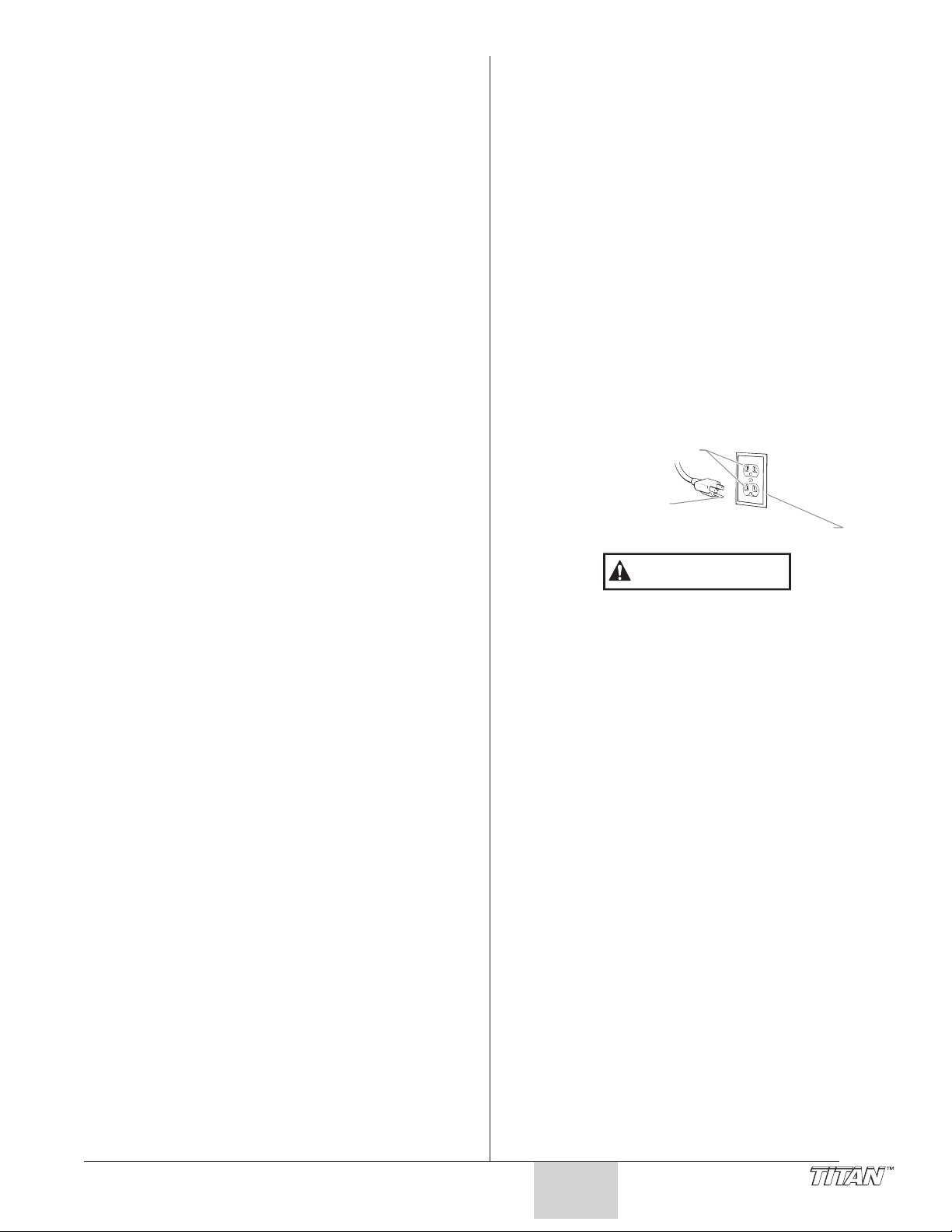
PELIGRO: PELIGRO DE EXPLOSIÓN DEBIDO A
PRECAUCION
Tomacorriente aterrado
Terminal de tierra
Tapa de la caja del tomacorriente aterrado
PARA PREVENIR:
• No utilice materiales que contengan blanqueador o cloro.
•
•
PELIGRO: GASES PELIGROSOS - Las pinturas, solventes,
ARA PREVENIR:
P
• Use una mascarilla respiratoria o careta siempre que
• Use gafas protectoras.
• Use ropa de protección, según lo requiera el fabricante
PELIGRO: GENERAL - Puede causar daños en la
PARA PREVENIR:
• Lea todas las instrucciones y advertencias de seguridad
• Desconecte siempre el motor del suministro eléctrico
• Observe todos los códigos locales, estatales y nacionales
• Los Estándares de Seguridad del Gobierno de los
• Utilice únicamente piezas autorizadas por el fabricante. El
• Antes de usarla cada vez, revise todas las mangueras para
• Todas las mangueras, soportes giratorios, pistolas y
• No atomice en días con viento.
• Use ropa que evite el contacto de la pintura con la piel y
MATERIALES INCOMPATIBLES - Podría
causar lesiones severas o daños en la
propiedad.
No use solventes con hidrocarburos halogenados, tales
omo productos para eliminar el moho, cloruro de
c
etileno y 1,1,1 - tricloroetano. Estos no son compatibles
m
on el aluminio.
c
Comuníquese con el proveedor del producto para obtener
nformación de compatibilidad con materiales de aluminio.
i
insecticidas y otros materiales pueden ser
perjudiciales si se inhalan o entran en contacto
con el cuerpo. Los gases pueden causar
náusea, desmayos o envenenamiento graves.
exista la posibilidad de que se puedan inhalar vapores.
Lea todas las intrucciones que vengan con la careta para
estar seguro de que se tendrá la protección necesaria
contra la inhalación de vapores dañinos.
del producto.
propiedad o lesiones severas.
antes de hacer funcionar cualquier equipo.
antes de dar servicio al equipo.
apropiados que rigen las medidas de ventilación,
prevención de incendios y operación.
Estados Unidos se han adoptado bajo el Acta de
Seguridad y Salud Ocupacionales (OSHA por sus siglas
en inglés). Deben consultarse estos estándares,
particularmente la parte 1910 de los Estándares
Generales y la parte 1926 de los Estándares de la
Construcción.
usuario asume todos los riesgos y responsabilidades si usa
piezas que no cumplen con las especificaciones mínimas y
dispositivos de seguridad del fabricante de la bomba.
ver que no tengan cortadas, fugas, una cubierta desgastada
por abrasión o con abolladuras, así como uniones dañadas
o que se hayan movido. Si existiera cualquiera de estas
condiciones, reemplace la manguera inmediatamente. No
repare nunca una manguera de pintura. Reemplácela con
otra manguera conectada a tierra.
accesorios que se usen con esta unidad deben tener una
capacidad de presión de 3300 lb/pulg2 / 22.8 MPa o
mayor.
el cabello.
Instrucciones para conectar a tierra
Este producto se debe conectar a tierra. En caso de que
ocurra un corto circuito, la conexión a tierra reduce el riesgo
de choque eléctrico al proporcionar un alambre de escape
para la corriente eléctrica. Este producto está equipado con
un cable que tiene un alambre de conexión a tierra con un
enchufe de conexión a tierra apropiado. El enchufe se debe
enchufar en una toma de corriente que se haya instalado y
conectado a tierra debidamente, de acuerdo con todos los
códigos y estatutos locales.
ELIGRO — Una instalación inapropiada del enchufe de
P
onexión a tierra puede dar como resultado el que exista un
c
iesgo de choque eléctrico. Si es necesario reparar o
r
eemplazar el cable o el enchufe, no conecte el alambre de
r
onexión a tierra a ninguno de los terminales de hoja planos.
c
l alambre con aislamiento que tiene la superficie exterior de
E
olor verde con franjas amarillas o sin ellas es el alambre de
c
onexión a tierra que debe conectarse al conector de conexión
c
tierra.
a
Verifique con un electricista o técnico de servicio calificado si
las instrucciones para conectar a tierra no le han quedado
completamente claras, o si duda que el producto haya
quedado conectado a tierra de manera apropiada. No
modifique el enchufe que se proporciona. Si el enchufe no
entra en la toma de corriente, pídale a un electricista calificado
que instale la toma apropiada.
Use solamente extensiones trifilares que tengan un
enchufe de conexión a tierra de 3 hojas y un receptáculo de
triple ranura que acepte el enchufe del producto.
Asegúrese de que su extensión esté en buenas
condiciones. Cuando use una extensión, asegúrese de
usar una que sea lo suficientemente resistente como para
soportar la corriente que descargue su producto. Un cable
de un tamaño menor causará una caída de voltage en la
línea que dará como resultado una pérdida de energía y un
sobrecalenta|ôento. Se recomienda usar un cable de
calibre 12. Si se utiliza un cable de extensión en el exterior,
tiene que estar marcado con el sufijo W-A después de la
designación del tipo de cable. Por ejemplo, SJTW-A para
indicar que el cable es apropiado para uso en exteriores.
© Titan Tool Inc. Todos los derechos reservados. 19
Español
Page 20
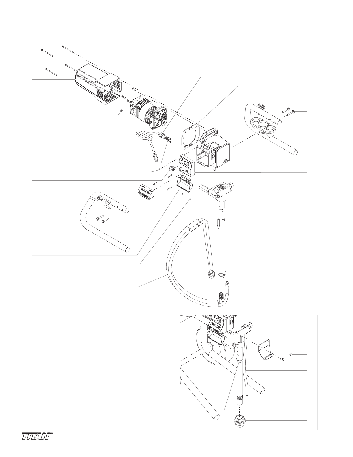
Parts List
1
3
6
5
7
8
9
10
4
11
2
16
17
18
19
20
21
22
23
24
14
15
13
12
High Rider Model
Main Assembly
20 © Titan Tool Inc. All rights reserved.
Page 21
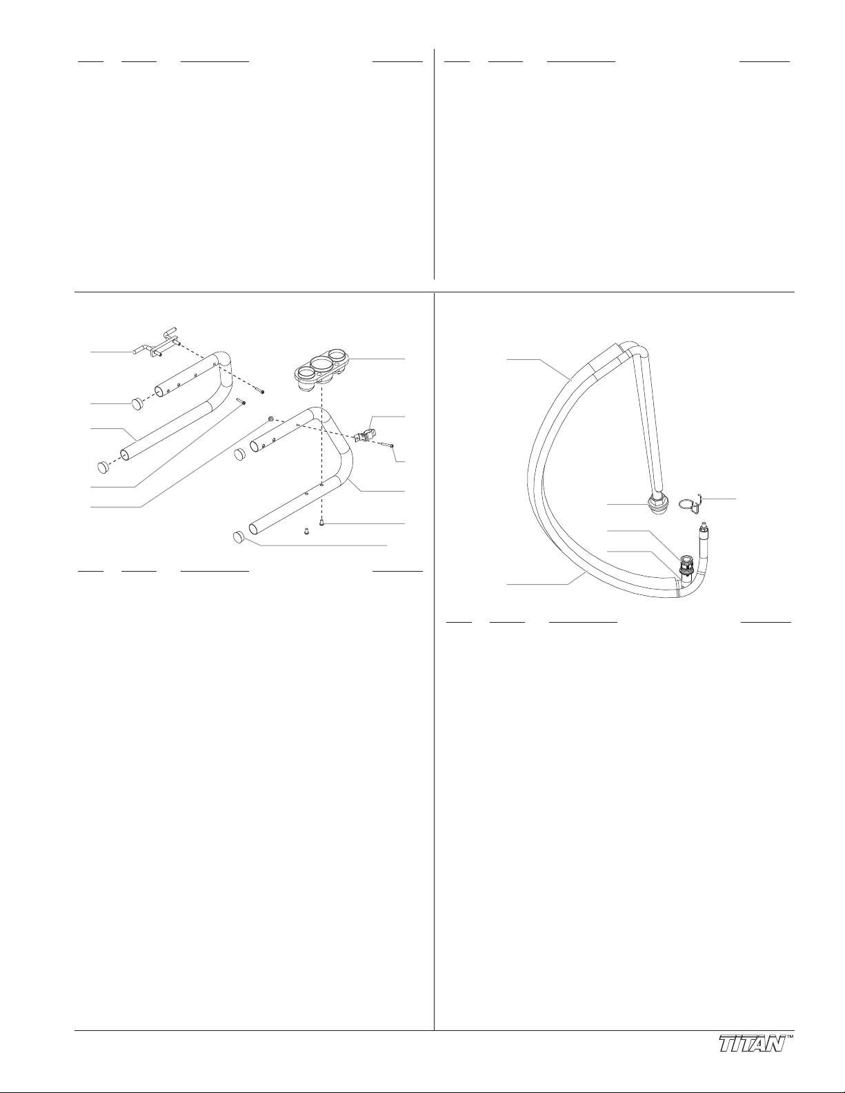
temPart #
1
3
4
5
2
6
7
8
9
10
2
1
2
3
4
5
6
I
704-181 Screw (includes washer and grommet) ......4
1
2 704-232 Motor cover.................................................1
700-681 Screw..........................................................4
3
4 704-499 Power cord (skid)........................................1
704-553 Power cord (high rider)
5 704-229 Ground screw .............................................1
6 704-486 Screw..........................................................4
7 704-488 Pressure control knob.................................1
8 704-469 Xact Digital Control System assembly
9 704-467 Xact Digital Control system cover
10 704-487 Screw..........................................................2
11 704-300 Siphon assembly (skid) ..............................1
12 765-063 Strain relief (skid)........................................1
704-369 Strain relief (high rider)
escription
D
optional).....................................................1
(
optional).....................................................1
(
uantity
Q
temPart #
I
3 704-331 Gasket ........................................................1
1
14 761-178 Hex screw ..................................................4
5 ---------- Skid assembly.............................................1
1
16 704-470 Control panel ..............................................1
17 704-538 Fluid section assembly (skid).......................1
704-571 Fluid section assembly (high rider)
18 704-117 Socket screw ..............................................2
19 704-304 Pail hook (high rider) ..................................1
20 710-033 Hex screw (high rider) ................................2
1 702-239 Return hose (high rider)..............................1
2
22 755-225 Siphon tube (high rider)..............................1
3 730-334 Hose clip (high rider) ..................................1
2
24 710-046 Inlet screen (high rider) .............................1
704-473 Control panel cover (for sprayers without
escription
D
Xact Digital Control System, not shown)
uantity
Q
Skid Assembly
Item Part # Description
1 700-761 Cord wrap...................................................1
2 710-199 Plug.............................................................4
3 704-164 Leg, left.......................................................1
4 700-642 Screw..........................................................2
5 226-001 Lock nut......................................................1
6 700-1043 Drip cup ......................................................1
7 704-244 Clip..............................................................1
8 704-243 Screw..........................................................1
9 704-163 Leg, right.....................................................1
761-188 Screw..........................................................2
10
704-179 Leg, left, complete
704-178 Leg, right, complete
(includes items 1–4)
(includes items 5–10)
Quantity
Siphon Assembly (P/N 704-300)
Item Part # Description Quantity
1 700-1023 Siphon tube assembly
2 704-263 Return hose................................................1
3 700-805 Inlet screen.................................................1
4 704-121 O-ring..........................................................2
704-109
5 700-1024 Elbow ..........................................................1
704-127 Retaining clip
6
7 755-135 Clip (not shown)..........................................1
(includes items 2–4, and 7) ........................1
O-ring (for hot solvents, optional)
..............................................
1
© Titan Tool Inc. All rights reserved. 21
Page 22
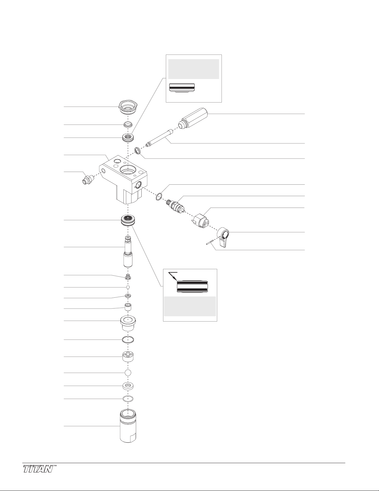
Fluid Section Assembly (Skid P/N 704-538, High Rider 704-571)
1
2
3
4
5
8
10
11
13
12
14
15
16
17
18
9
7
6
20
21
22
23
24
26
25
19
Install upper packing
with raised lip and
O-ring facing down.
O-Ring
Raised Lip
Install lower packing
with the beveled
edge facing up.
Beveled Edge
22 © Titan Tool Inc. All rights reserved.
Page 23
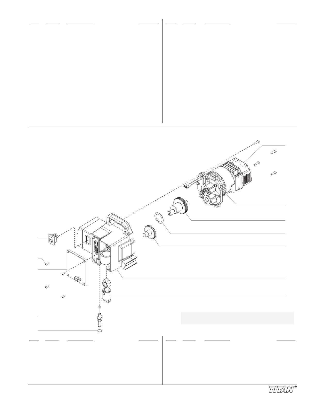
Item Part # Description Quantity
3
1
4
5
2
7
6
8
9
10
11
12
1 730-508 Retainer nut................................................1
2 700-587 Piston guide................................................1
3 704-564 Upper packing assembly with tool..............1
4 704-532 Pump block.................................................1
5 227-006 Outlet fitting.................................................1
6 704-547 Lower packing assembly ............................1
7 704-551 Piston rod....................................................1
8 704-557 Outlet cage .................................................1
9 762-144 Outlet valve ball..........................................1
10 704-558 Outlet valve seat.........................................1
11 704-587 Outlet valve retainer ...................................1
2 755-186 Piston bushing ............................................1
1
3 700-821 Foot valve seal ...........................................1
1
4 730-510 Inlet cage ....................................................1
1
5 762-145 Foot valve ball ............................................1
1
6 762-137 Foot valve seat ...........................................1
1
7 762-058 O-ring, Teflon ..............................................1
1
8 704-054 Foot valve housing (skid)............................1
1
730-511 Foot valve housing (high rider)
Drive Assembly
Item Part # Description Quantity
19 700-421 Filter housing ..............................................1
20 540-030 Filter............................................................1
21 560-038 Seal.............................................................1
22 700-537 Gasket ........................................................1
23 800-925 Valve housing assembly.............................1
24 700-252 Cam base ...................................................1
25 700-697 Valve handle...............................................1
26 700-759 Groove pin ..................................................1
27 762-202 Packing tool (not shown) ............................1
700-258 PRIME/SPRAY valve assembly
704-560 Piston assembly (includes items 7–11)
04-586 Repacking kit (includes items 2, 3, 6, 8, 9,
7
(includes items 22—26)
13, 15, and 17. Also included are packing
grease P/N 700-203 and piston guide tool
P/N 700-793.)
Item Part # Description Quantity
1 704-380 ON/OFF Switch...........................................1
2 700-139 Screw..........................................................8
3 704-019 Front cover..................................................1
704-492
4
5 704-584 Transducer o-ring .......................................1
704-588
6
704-589 Motor...........................................................1
7
ransducer assembly (includes item 5)
T
Electronic pressure control (EPC)
......
..............1
Item Part # Description Quantity
10 704-176 2nd stage gear............................................1
11 704-510 Pump housing.............................................1
1
12 700-2060 Slider assembly ..........................................1
13
NOTE: All electrical work should be performed
8 704-173 Crankshaft/gear assembly..........................1
9 704-174 Thrust washer.............................................1
704-548
704-522
by an authorized service center.
ransducer jumper wire (not shown)
T
Motor assembly (includes items 6 and 7)
..........
1
© Titan Tool Inc. All rights reserved. 23
Page 24
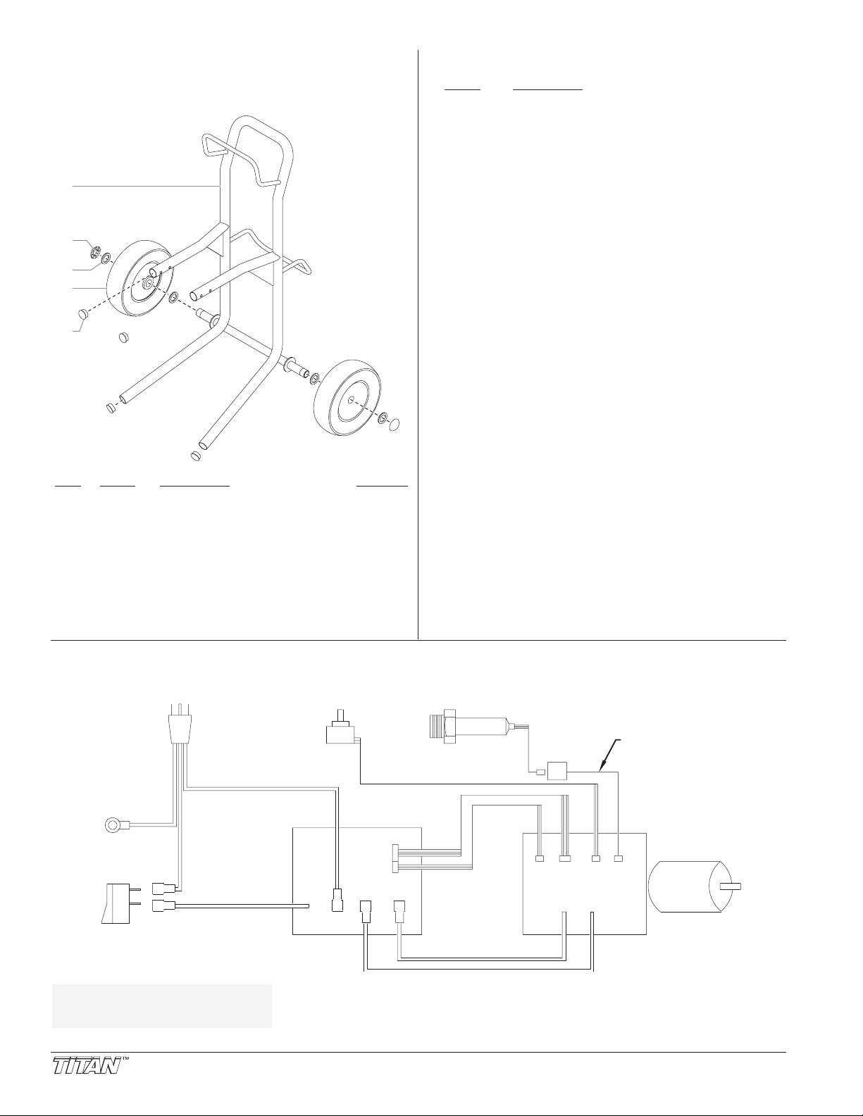
Potentiometer
Motor
Transducer
Transducer
Jumper
Plug
WHITE
WHITE
WHITE
BLACK
BLACK
GREEN
Control Panel
Board
Electronic Pressure
Control (EPC)
J16
AC-Motor
AC-NeutAC-Line
AC-Motor
J9
J2 J1
J12 J7
Switch
Ground
High Rider Cart Assembly
1
2
3
5
4
(P/N 704-574)
Labels
Part # Description
313-1638 Front cover label
313-1629 Motor cover label
313-1673 Warning label
313-1847 Shock hazard label
313-1906 Infinity motor label
313-2324 X-Lock label
313-2327 Xact Digital Control System label
13-2328 Xact Instruction label
3
(injection/explosion)
Item Part # Description Quantity
1 704-573 Cart weldment (includes item 5).................1
2 704-355 Cap .............................................................2
3 704-354 Spacer ........................................................4
4 704-353 Wheel..........................................................2
5 710-199 Plug.............................................................4
Electrical Schematic
NOTE:
All electrical work should
be performed by an
authorized service center
.
24 © Titan Tool Inc. All rights reserved.
Page 25
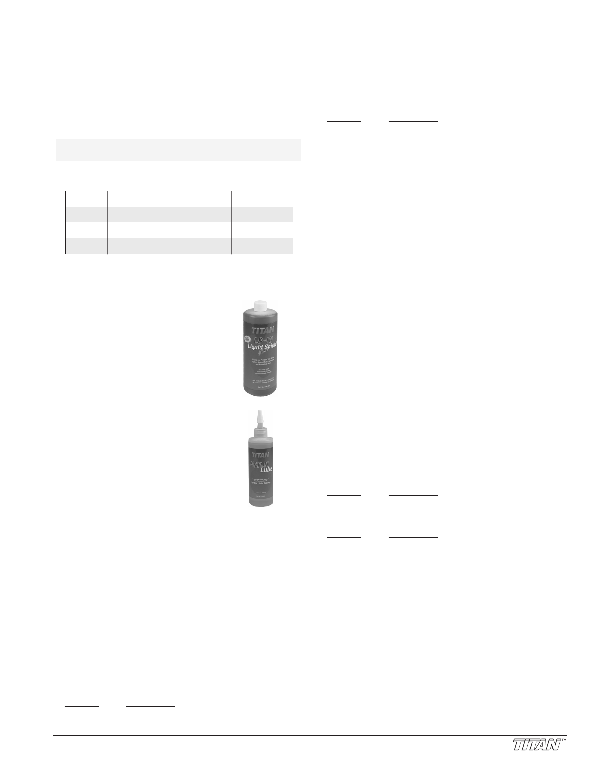
Accessories
T
ip Size Spray Material Filter Type
.011 – .013 Lacquers and stains 100 mesh filter
.015 – .019 Oil and latex 60 mesh filter
.021 – .026 Heavy bodied latex and blockfillers 30 mesh filter
A
irless Tip Selection
Tips are selected by the orifice size and fan width. The proper
selection is determined by the fan width required for a specific
job and by the orifice size that will supply the desired amount
of fluid and accomplish proper atomization.
For light viscosity fluids, smaller orifice tips generally are
desired. For heavier viscosity materials, larger orifice tips are
preferred. Please refer to the chart below.
NOTE: Do not exceed the sprayer's recommended tip
The following chart indicates the most common sizes and the
appropriate materials to be sprayed.
Fan widths measuring 8" to 12" (20 to 30 cm) are preferred
because they offer more control while spraying and are less
likely to plug.
Liquid Shield Plus
Cleans and protects spray systems
against rust, corrosion and premature
wear. Now with -25º anti-freeze
protection.
Piston Lube
Specially formulated to prevent materials
from adhering to the piston rod, which
becomes abrasive to the upper seals.
Piston Lube will break down any material
that may accumulate in the oil cup and
keep it from drying.
size.
Part # Description
314-483...........4 ounce bottle
314-482...........1 quart bottle
Part # Description
314-481...........
314-480...........8 ounce bottle
4 ounce bottle
S
ynergy Fine Finish Tips
Perfect for all fine finish work
•
• Ideal for lacquers, stain, enamels, urethane, and clear top
coats
• Increases standard tip life up to 80%
• Delivers up to a 27% finer atomization at lower pressures
• Increases transfer efficiency resulting in less overspray
art No.
P
671-XXX ..........Synergy Fine Finish Tips
escription
D
WideSpray Reversible Tips
• Designed for high production applications
• Increase production up to 100%
• WideSpray will save time and make you more money
Part No. Description
661-XXXX .........WideSpray Reversible Tips
I-Remote Universal Remote Control System
• Operates your sprayer from over 100 feet away
Works through walls, trees and other obstacles
•
• Increase or decrease the pressure of the sprayer without
climbing down off the ladder
Part No. Description
800-690...........I-Remote Control System
800-691...........I-Remote Control Only
800-692...........I-Remote Receiver Only
Xact Digital Control System
The Xact Digital Control System is an optional add-on that
increases the functionality of the sprayer. It consists of a
display and four function keys. The display shows the user
menu features that enable the user to become more
productive and profitable
• X-Lock Security Features (Individualized Codes)
• Pressure Reading — Set Pressure and Working Pressure
• User Preset Keys
• Total Gallons Sprayed
• Resetable Job Gallon Counter
• Total On Time and Run Time
• Resetable On Time and Run Time
• Programmable Service Time (Hour Meter)
• Advanced Diagnostics
Part No. Description
704-555...........Xact Digital Control System with Cover
LX-80IIAirless Gun
• 3600 PSI
•
All metal construction
• In-handle filter
• High pressure swivel
Part No. Description
580-100...........
581-085
580-050...........LX-80II — 4 Finger GTH Kit
581-150...........LX-80II — 2 Finger GTH Kit
LX-80II — 4 Finger Gun
...........LX-80II — 2 Finger Gun
S-3 Stainless Steel Airless Gun
• 3900 PSI
• Stainless Steel fluid passages
• High Pressure Swivel
• In-handle filter
• 4-finger trigger pull
Part No. Description
550-250
© Titan Tool Inc. All rights reserved. 25
S-3 — 4 Finger Gun
...........
Miscellaneous
Part No.
490-012...........Hose Coupling, 1/4" x 1/4"
730-397...........High Pressure Fl. Gauge
314-171
314-172...........Lubriplate, 6 lb. can
700-1037
Description
...........Lubriplate, 14 ounce individual
Electrostatic discharge (ESD) wrist strap
..........
Page 26

Notes
26 © Titan Tool Inc. All rights reserved.
Page 27

Notes
© Titan Tool Inc. All rights reserved. 27
Page 28

Warranty
United States Sales & Service
1-800-526-5362
Fax 1-800-528-4826
107 Bauer Drive
Oakland, NJ 07436
www.titantool.com
Canadian Branch
1-800-565-8665
Fax 1-905-856-8496
200 Trowers Road, Unit 7B
Woodbridge, Ontario L4L 5Z8
International
1-201-337-1240
Fax 1-201-405-7449
107 Bauer Drive
Oakland, NJ 07436 USA
Titan Tool, Inc., (“Titan”) warrants that at the time of delivery to the original purchaser for use (“End User”), the equipment
covered by this warranty is free from defects in material and workmanship. With the exception of any special, limited, or
extended warranty published by Titan, Titan’s obligation under this warranty is limited to replacing or repairing without charge
those parts which, to Titan’s reasonable satisfaction, are shown to be defective within twelve (12) months after sale to the End
User. This warranty applies only when the unit is installed and operated in accordance with the recommendations and
instructions of Titan.
This warranty does not apply in the case of damage or wear caused by abrasion, corrosion or misuse, negligence, accident,
faulty installation, substitution of non-Titan component parts, or tampering with the unit in a manner to impair normal operation.
Defective parts are to be returned to an authorized Titan sales/service outlet. All transportation charges, including return to the
factory, if necessary, are to be borne and prepaid by the End User. Repaired or replaced equipment will be returned to the End
User transportation prepaid.
THERE IS NO OTHER EXPRESS WARRANTY. TITAN HEREBY DISCLAIMS ANY AND ALL IMPLIED WARRANTIES
INCLUDING, BUT NOT LIMITED TO, THOSE OF MERCHANTABILITY AND FITNESS FOR A PARTICULAR PURPOSE, TO
THE EXTENT PERMITTED BY LAW. THE DURATION OF ANY IMPLIED WARRANTIES WHICH CANNOT BE DISCLAIMED IS
LIMITED TO THE TIME PERIOD SPECIFIED IN THE EXPRESS WARRANTY. IN NO CASE SHALL TITAN LIABILITY EXCEED
THE AMOUNT OF THE PURCHASE PRICE. LIABILITY FOR CONSEQUENTIAL, INCIDENTAL OR SPECIAL DAMAGES
UNDER ANY AND ALL WARRANTIES IS EXCLUDED TO THE EXTENT PERMITTED BY LAW.
TITAN MAKES NO WARRANTY AND DISCLAIMS ALL IMPLIED WARRANTIES OF MERCHANTABILITY AND FITNESS FOR A
PARTICULAR PURPOSE WITH RESPECT TO ACCESSORIES, EQUIPMENT, MATERIALS OR COMPONENTS SOLD BUT NOT
MANUFACTURED BY TITAN. THOSE ITEMS SOLD, BUT NOT MANUFACTURED BY TITAN (SUCH AS GAS ENGINES,
SWITCHES, HOSES, ETC.) ARE SUBJECT TO THE WARRANTY, IF ANY, OF THEIR MANUFACTURER. TITAN WILL PROVIDE
THE PURCHASER WITH REASONABLE ASSISTANCE IN MAKING ANY CLAIM FOR BREACH OF THESE WARRANTIES.
Patents
These products are covered by one or more of the following U.S. patents:
6,031,352 5,848,566 5,769,321 5,725,364 5,671,656 5,435,697 5,228,842
5,346,037 5,252,210 5,217,238 5,192,425 4,908,538 4,768,929 4,744,571
D384,676 6,179,222 5,934,883 4,723,892
Material Safety Data Sheets (MSDS) are available on Titan’s website or by calling Customer Service.
28 © Titan Tool Inc. All rights reserved.
 Loading...