

Page 1
Instruction manual
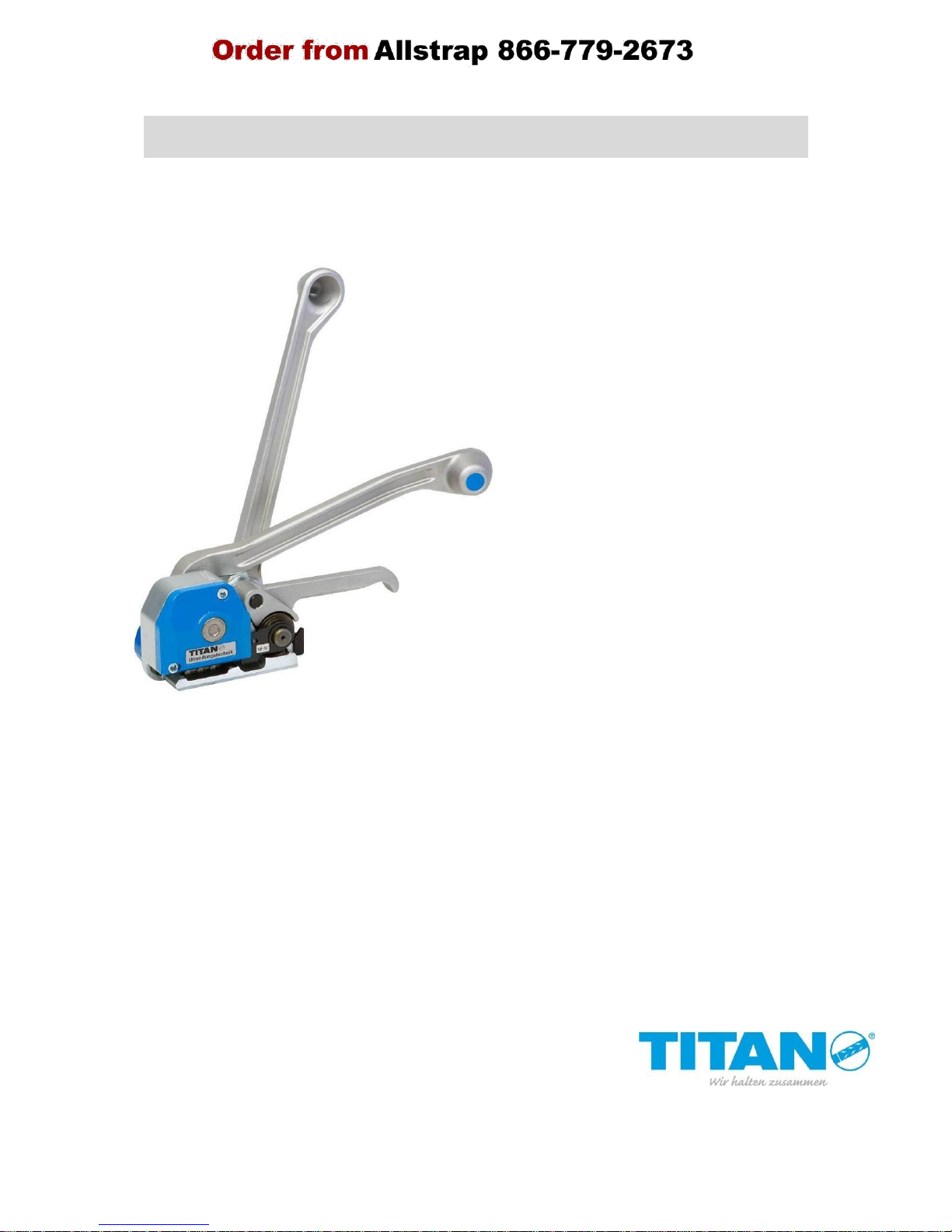
HKE-L
223 000200
Combined strapping tool for
steel strap
Important!
Do not dispose of this manual. It is the
customers responsibility to ensure that all
operators and servicemen read and understand
this manual.
Page 2

HKE-L
H 223 EU 03/11
2.
General information
Many thanks for your confidence in the technology of
TITAN Umreifungstechnik GmbH & Co. KG
These operating instructions are intended to simplify familiarisation with the HKE-L and the
possibilities of application for the intended purpose. The operating instructions contain
important information concerning the safe, proper and efficient use of the strapping
tool. Following the instructions helps avoid risks, reduces repairs and downtimes and
increases reliability and life of the unit.
The operating instructions must always be available at the place of operation of the strapping
tool. They must be read and observed by persons concerned with work on the strapping tool.
This work specifically includes operation, refilling of operating material, fault elimination and
maintenance.
In addition to the operating instructions and the regulations for accident prevention effective
in the country of use and place of application, the recognized technical regulations for safety
and proper working must also be observed.
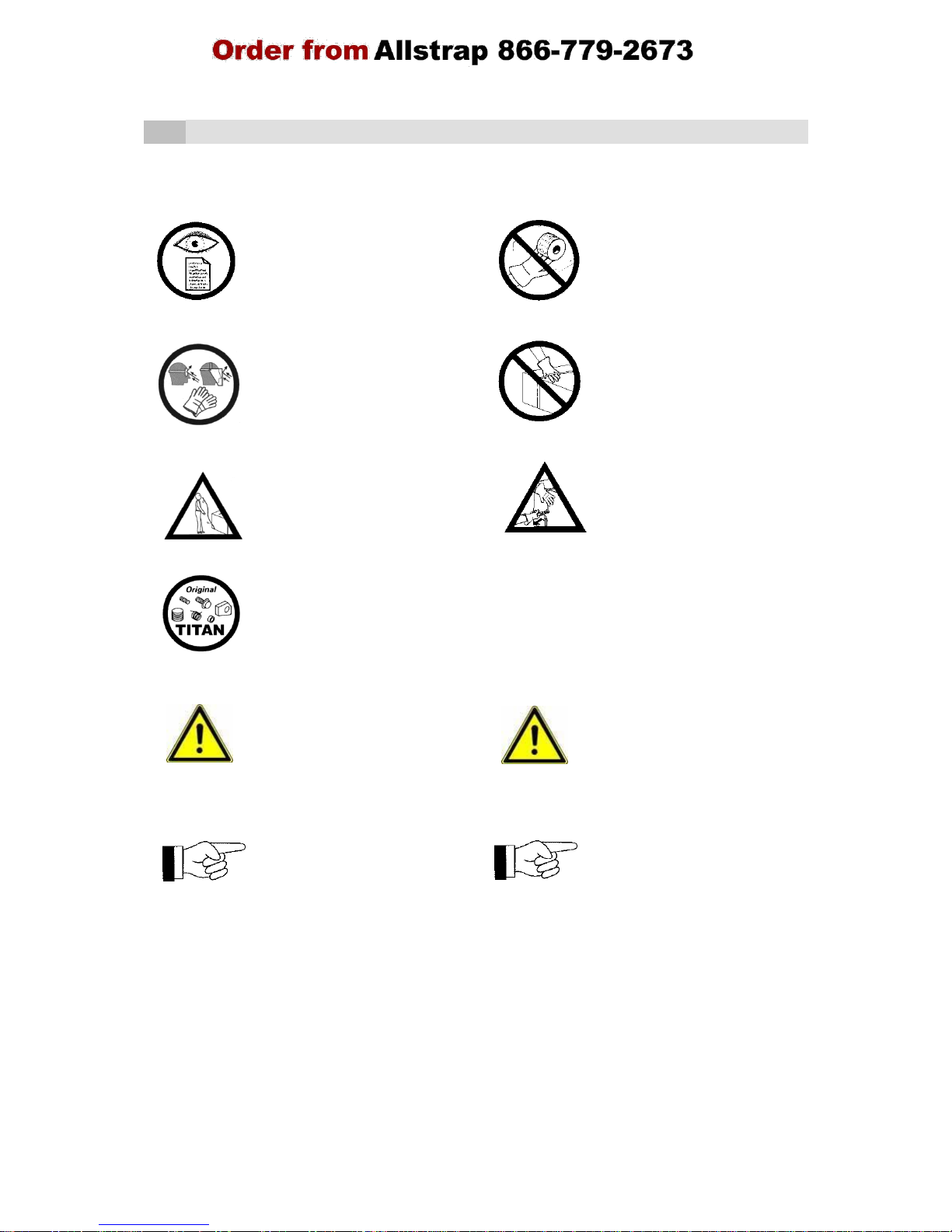
Explanatory notes on the warning and instruction symbols:
Caution!
Used where there is danger to life and health.
Attention!
Used for danger which cause material damage.
Note!
Used for general information and information which if not followed can cause
faults in the operating sequences.
The manufacturer reserves the right to make changes to the scope of delivery
at any time for the purpose of improving the product.
Copyright © TITAN Umreifungstechnik GmbH & Co.KG 2011 All rights reserved.
The contents of this document must not be duplicated, handed to third parties, published or saved in any form,
neither fully nor partly, without prior written permission by TITAN Umreifungstechnik GmbH & Co.KG.
is a registered trademark of TITAN Umreifungstechnik GmbH & Co.KG.
Page 3

HKE-L
H 223 EU 22/11
2.1.
Intended use
This tool is made for strapping packages, pallet loads etc. The tool is designed
and manufactured for safe handling during the strapping operation.
This tool is intended for strapping with steel strap material.
Unintended use!
Strapping material must not be used for the hoisting of loads; this strapping
tool may only be used as intended and specified above.
The use of plastic straps is not allowed with this device.
The strapping tool HKE-L complies with the German and European safety
standards and is in accordance with EU Guidelines: see Declaration of
conformity of the machinery.
Standards applied and technical specifications:
See Declaration of conformity of the machinery.
2.2.
Warranty & liability
TITAN Umreifungstechnik GmbH & Co. KG guarantees all strapping tools
sold by the company for a period of 6 months. The warranty covers all
defects that can be demonstrated to result from faulty craftsmanship or
defective materials.
Wear parts are excluded from the warranty.
Warranty and liability claims shall be excluded if they are due to one or more of
the following causes:
Misuse of the tool.
Incorrect assembly, commissioning, operation and maintenance of the tool.
Operation of the tool with improper safety and protective devices.
Failure to comply with the information in the operating manual.
Unauthorized structural modifications to the tool.
Insufficient monitoring of tool parts that are subject to wear.
Improper repairs.
2.3.
Information on environmental protection
This tool is manufactured without any physical or chemical
substances which could be dangerous to health. For disposal of
all the parts, the governmental instructions must be observed.
Page 4
HKE-L
H 223 EU 33/10
3.
Safety instructions
Failure to comply with the following safety instructions, in addition to errors in
handling the device, can result in serious injuries.
Be informed!
Caution: Danger of crushing!
Read the operating manual
Do not insert fingers into the
carefully before using the
pulley area.
device.
Protect yourself!
Caution:
Always wear eye, face and hand
Strap only objects to be
protection (cut-resistance
packed!
gloves) when working.
Make sure that no hands or
other body parts are between
the strap and the goods to be
packaged.
Attention: Strap can break!
Attention: Strap flies outward!
The strap can break during
When cutting the strap, hold the
tightening! Do not stand in the
top part firmly and stand to the
path of the strap. Make sure that
side.
no one else is in the working
Attention: The lower part of the
area.
strap will fly outward.
Use only original TITAN
replacement parts!
The use of other than original
TITAN replacement parts will
void the warranty and all liability.
The use of straps other than
This tool may be operated only
recommended can result in
by personnel who have been
broken straps during the
trained accordingly. Please
tightening process and
consult your TITAN packaging
insufficient strapping. Use only
consultant if you have any
corresponding quality
questions about this.
products from TITAN!
Workplace!
Always maintain an orderly
workplace. A disorderly
workplace can cause accidents.
When operating the crimper,
make sure that you‟re in a wellbraced position in order to
maintain optimum balance and
prevent the risk of falling. Never
operate the tool in an awkward
working position!
Maintenance!
In order to operate safely, the
tool must be properly
maintained. Check the condition
of your tool regularly for defects
or worn parts. Never use a tool
that has defects or worn parts.
Modifications to the tool are
strictly prohibited. Failure to
comply with this regulation can
result in serious injury.
Page 5

HKE-L
H 223 EU 22/11
4.
Technical data
Joint: No seal joint
Tension force: up to approx. 6.000 N
Weight: 3.2 kg
Dimension: L = 475 mm
B = 115 mm
H = 190 mm
Steel strap for
strap width 13, 16, 19 mm
Standard quality
(Automatenband)
High quality
(Megaband)
Strap thickness
0.4 – 0.6 mm
0.4 – 0.63 mm
Tensile strength
up to approx. 900 N/mm²
up to approx. 1.100 N/mm²
Page 6
HKE-L
H 223 EU 21/06
5.
Description
5.1.
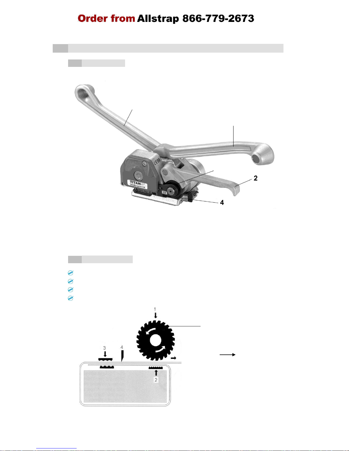
Design
29 = Tension wheel 503 = Gripper plate
35 = Cutting lever 508 = Tension lever complete
509 = Rocker complete
5.2.
Function
Strap clamped by pressure on gripper plate1/2
Tensioning by turning feed wheel 1
Sealing by punching the strap 3
Cutting the strap with cutter 4
Attention!
When changing the feed wheel
strictly observe the moving
direction!
Arrow
508
35
29
509
503
Page 7
HKE-L
H 223 EU 21/06
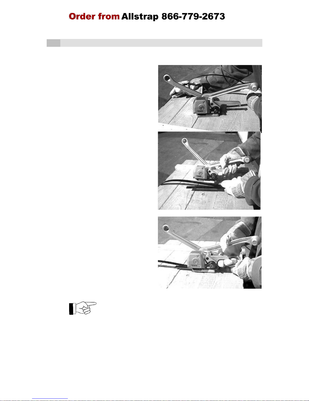
6.
Operating instructions
1.
TITAN steel strap around package
from top. Pull end of strap until it is
positioned in the middle of the
package below the upper strap.
2.
Pull through the strap end until it is in
the centre of the package beneath
the upper run of strap and juts out
approx. 15 cm.
3.
With the left hand hold the upper and
lower run of the strap together. Both
straps must be placed exactly on top
of one another. Grip and press rocker
509 together with the cutting lever 35
with the right hand. Insert the steel
strap laterally until it strikes against
the case wall, ensuring that the lower
run of strap projects slightly out of the
tool at the front. The right hand now
releases the levers which have been
pressed together.
If the straps are not inserted correctly in the tool, it is not possible to
perform the tensioning operation.
Page 8

HKE-L
H 223 EU 21/06
4.
If necessary, tighten the great
strap loop. The left hand pulls the
strap loop, the right hand grasps
the lifting Rocker 509.
5.
The right hand grasps the tension
lever 508 and moves it back and
forth to obtain the desired strap
tension. At the same time the left
hand holds the cutting lever 35.
6.
After having reached the desired
strap tension bring tension lever
508 back into its initial position.
The right hand remains there and
provides support for the joining
process. The TITAN “No-seal” joint
is formed by pushing the cutting
lever 35 forwards rapidly with the
left hand until it strikes against the
case; the steel strap is
simultaneously cut off directly
behind the joint.
7.
Bring tension lever 508 back into
its initial position. Grasp and press
together rocker 509 with cutting
lever 35. Withdraw the tool from
the package by a rotary movement
to the right side.
Page 9
HKE-L
H 223 EU 05/10
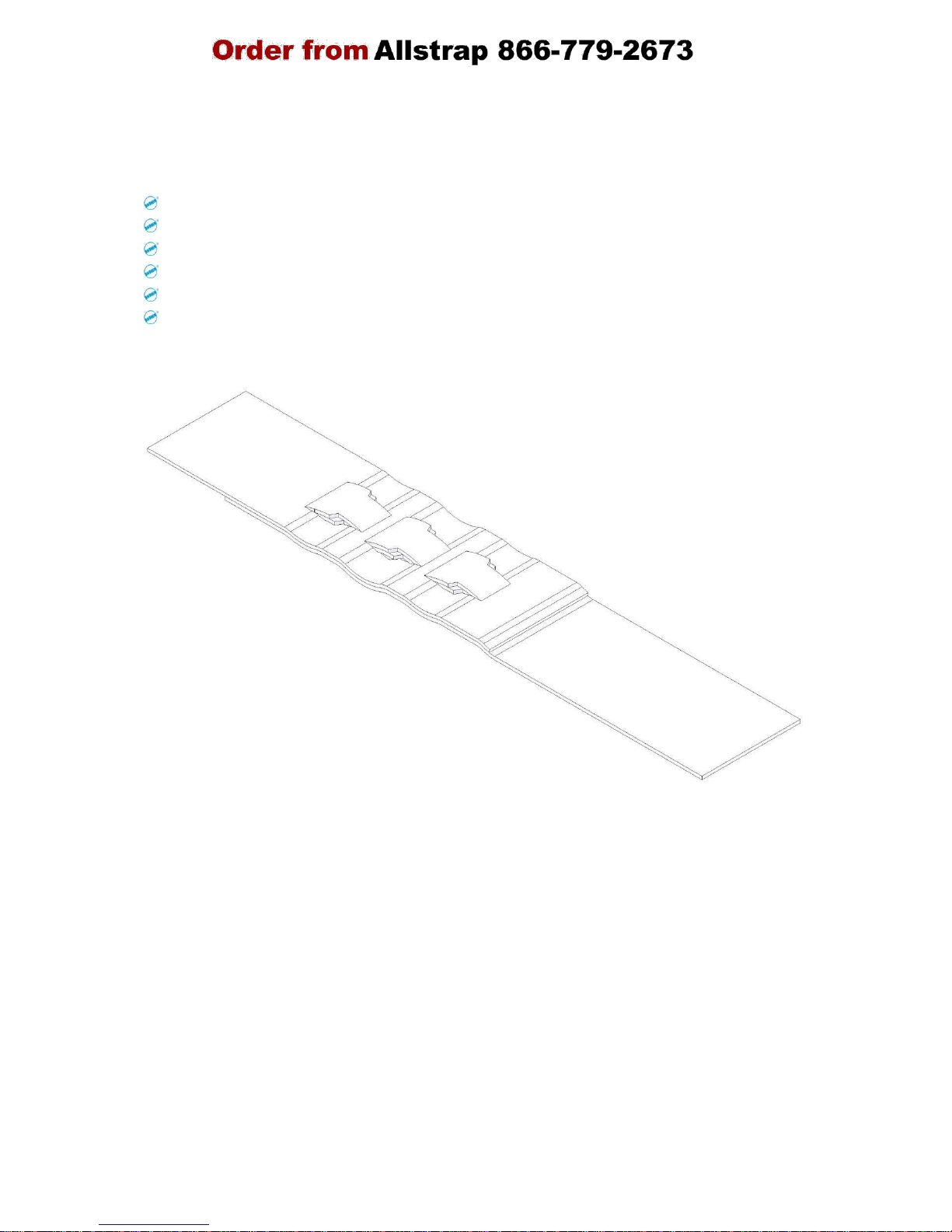
The following picture shows a correctly carved seal.
Check the seals regular:
for even carved cuttings,
for neat cutting edges,
for that the lower run of strap is soaked in the cuttings,
for correct adjustment of the cutter,
for a sufficient overlap of the lower run of strap and
for that the seal is placed in the centre of the strap.
Page 10

HKE-L
H 223 EU 21/06
7.
Adjustments
7.1.
Cutter adjustment
The cutter has been adjusted for the
respective thickness in the case of
varying strap thicknesses.
Release hexagon nut 72, turn set screw
49 (thread pin with flat point) by means
of a screwdriver,
clockwise = less cutting
depth
counter clockwise = greater cutting
depth
Fasten hexagon nut 72 after adjustment has been completed.
Note! After adjustment there should not be any, or very
few, signs of cutting on the lower strap.
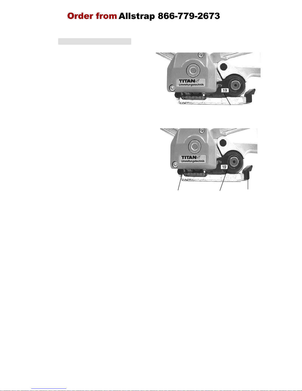
7.2.
Distance between the feed wheel and the gripper plate
The distance between the feed wheel 29
and the gripper plate 503 is adjusted to
0.2 mm. The adjusting screw 84 is
located behind the plastic cover of the
housing. Unscrew the hexagon nut 8
using the 10 mm open-jawed spanner
and adjust a 0.2 mm gap at the
adjusting screw 84.
Note!
The feed wheel and the gripper plate may not come
into contact with each other. Otherwise both parts
will be subject to premature wear.
72
49
84
8
Page 11
HKE-L
H 223 EU 21/06
The strap guide 500 located next to the
feed wheel is replaced when the strap
width is modified. In order to do so the
safety ring has to be removed by means
of a screwdriver and the lifting rocker
509 and the cutting lever 35 pressed
together. The strap guide may now be
pulled off towards the front and be
replaced with the strap guide for other
strap widths. Replace safety ring
afterwards.
Since the strap is guided at three points
in the tool the rear strap guide 42 and
the strap guide front 76 also have to be
set in such a way that the punching is
placed at the centre of the strap.
In order to do this, loosen the two
fastening screws for the rear strap guide
42 and adjust the strap guide to the
respective strap width.
Left = 13mm
Middle = 16mm
Right = 19mm
Fasten screws afterwards.
Also loosen the cap screw at the front strap guide 76 and place the corresponding
number of washers DIN 125-6.4 under the strap guide:
13 mm band width = 2 washers
16 mm band width = 1 washer
19 mm band width = no washer
Fasten cap screw again after adjustment.
7.3. Adjusting strap width
500
76
500
42
Page 12

HKE-L
H 223 EU 05/10
8.
Maintenance
8.1.
Cleaning the tool
Soil and debris hamper the proper functioning of the tool. For this
reason the following areas should be cleaned once a week.
Insertion slot
Cavities between the upper and lower jaws
Tensioning wheel
Gripper plate
Blow off using compressed air if possible (wear protection goggles).
Lubricate with fine conventional spray oil afterwards.
8.2.
Tool inspection
Perform a daily visual inspection of the outside of the unit. The early detection of
damaged parts extends the life of the unit. Replace all damaged parts immediately
with Original TITAN spare parts.
For health reasons please do not use any cleaning
agents which contain solvents.
Page 13

9. Declaration of conformity of the machinery
 Loading...