

Page 1
B ENGINE
A
FL
SECTION
CONTENTS
PREPARATION ........................................................... 2
Special Service Tools ............................................... 2
Commercial Service Tool ......................................... 2
FUEL SYSTEM ........................................................... 3
Checking Fuel Lines ................................................. 3
General Precautions ................................................ 3
FUEL LEVEL SENSOR UNIT, FUEL FILTER AND
FUEL PUMP ASSEMBLY ........................................... 5
Removal and Installation .......................................... 5
REMOVAL ............................................................. 6
INSTALLATION ..................................................... 8
INSPECTION AFTER INSTALLATION ................. 8
FUEL SYSTEM
FUEL TANK ................................................................ 9
Removal and Installation .......................................... 9
REMOVAL ...........................................................10
INSTALLATION ...................................................12
INSPECTION AFTER INSTALLATION ................13
SERVICE DATA AND SPECIFICATIONS (SDS) ......14
Standard and Limit ..................................................14
C
D
E
F
G
H
I
J
K
M
L
Revision: April 2004 2004 Titan
FL-1
Page 2
PREPARATION
PREPARATION PFP:00002 Special Service Tools
The actual shapes of the Kent-Moore tools may differ fr om those of the special tools illustrated here.
Tool number
(Kent-Moore No.)
Tool name
—
(J-46536)
Fuel tank lock ring tool
LBIA0398E
Description
Removing and installing fuel tank lock ring
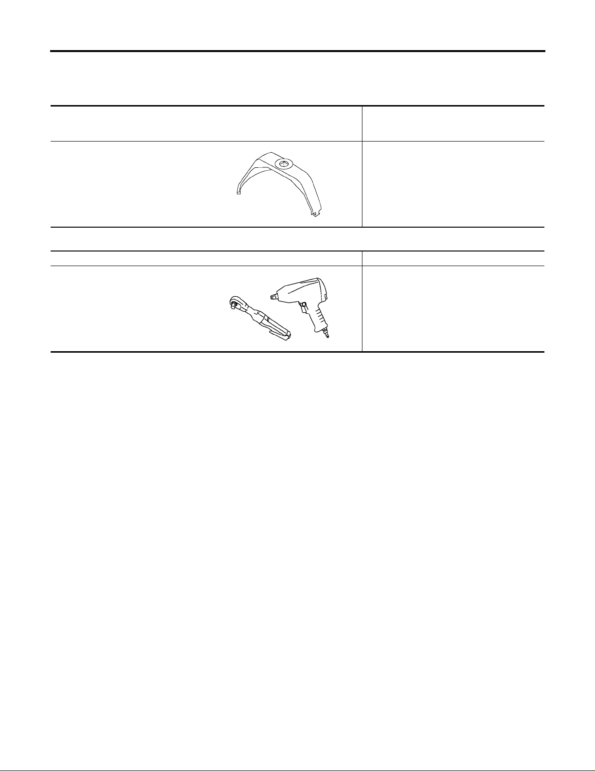
Commercial Service Tool
Tool name Description
Power tool Loosening bolts and nuts
PBIC0190E
EBS00I00
EBS00I01
Revision: April 2004
FL-2
2004 Titan
Page 3
FUEL SYSTEM
FUEL SYSTEM PFP:17503
Checking Fuel Lines
Inspect fuel lines, fuel filler cap and fuel tank for improper attachment, leaks, cracks, damage, loose connections, chafing or deterioration.
If necessary, repair or replace damaged parts.
General Precautions
WARNING:
When replacing fuel line part s, be sure to observe the following.
● Put a “CAUTION: INFLAMMABLE” sign in the workshop.
● Be sure to work in a well ventilated area and furnish workshop with a CO2 fire extinguisher.
● Do not smoke whi l e ser v ic ing fu el syst e m. Ke ep op e n fl a mes and sparks aw ay f rom t he wo rk a r ea.
CAUTION:
● Before removing fuel line parts, carry out the following procedures:
– Put drained fuel in an e xpl osi on-p roof c ontainer and put the lid on securely. Keep the container in
safe area.
– Release fuel pressure from the fuel lines. Refer to EC-46, "FUEL PRESSURE RELEASE" .
– Disconnect the battery negative terminal.
● Always replace O-rings and clamps with new ones.
● Do not kink or twist hoses when they are being installed.
● Do not tighten hose clamps excessively to avoid damaging hoses.
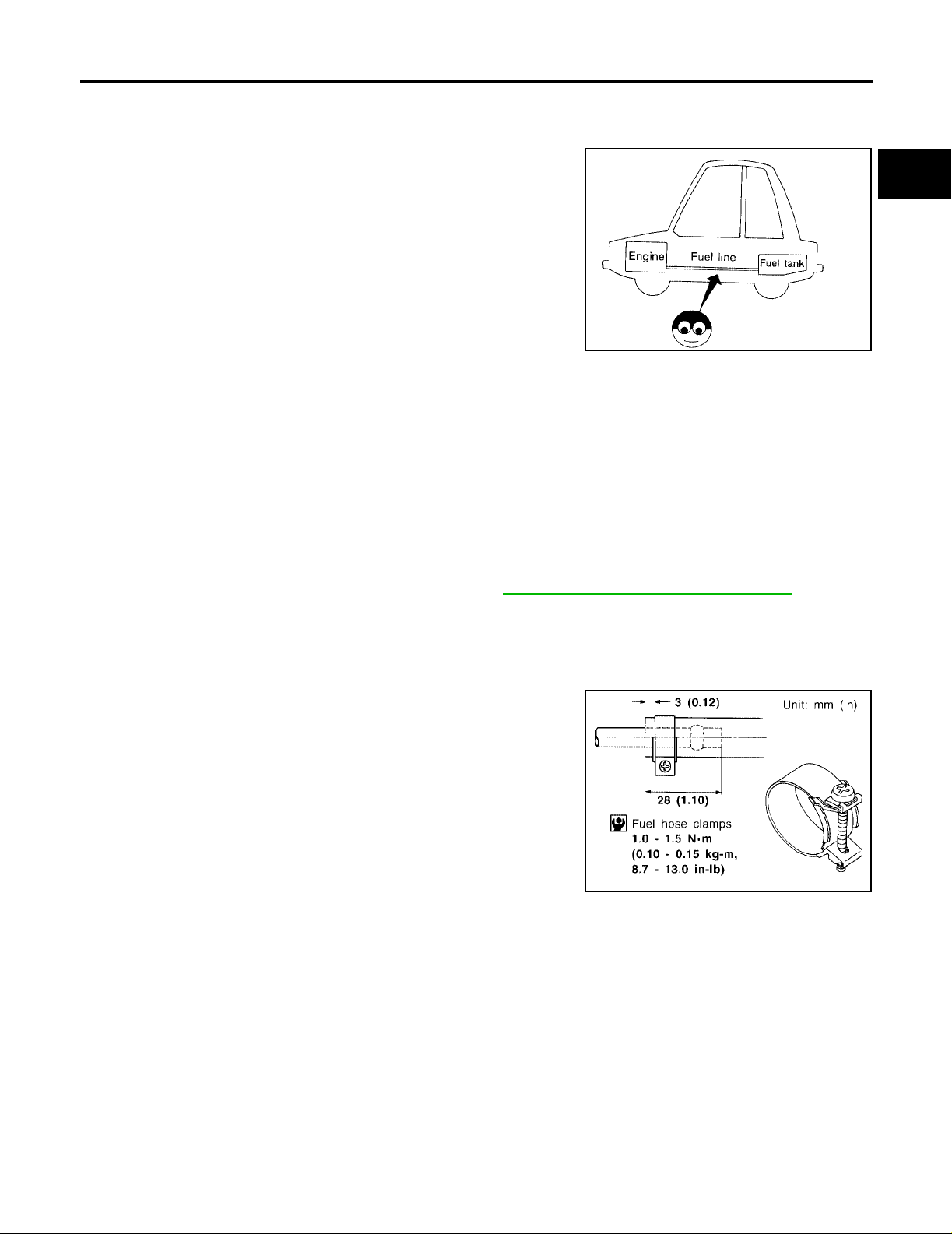
Tighten high-pressure rubber hose clamp so that clamp
end is 3 mm (0.12 in) from hose end.
Tightening torque specification s are the s ame for al l ru bber
hose clamps.
Ensure that screw does not contact adjacent parts.
EBS00I02
SMA803A
EBS00I03
A
FL
C
D
E
F
G
H
I
J
K
L
MMA104A
Revision: April 2004 2004 Titan
FL-3
M
Page 4
FUEL SYSTEM
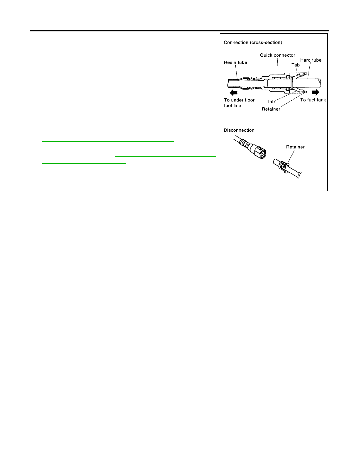
● After connecting the fuel tube q uic k c onn ec tors, ma ke su re
the quick connectors are secure.
Ensure that the connector and resin tube do not contact
any adjacent parts.
● After installing tubes, make sure there is no fuel leakage at
connections in the following steps.
– Apply fuel pressure to fuel lines with turning ignition switch
ON (with engine stop pe d). The n c he ck for fue l l eaks a t co nnections.
– Start the engine and rev it up and check for fuel leaks at
connections.
● Use only a Genuine NISSAN fuel filler cap as a replacement.
If an incorrect fuel filler cap is used, the MIL may come on.
● For servici ng “E vapora ti ve Emis sio n Syst em” p ar t s, refe r to
EC-605, "
● For servicing “On Board Refueling Vapor Recovery
(ORVR)” parts, refer to EC-612, "
VAPOR RECOVERY (ORVR)" .
EVAPORATIVE EMISSION SYSTEM" .
ON BOARD REFUELING
PBIC1268E
Revision: April 2004
FL-4
2004 Titan
Page 5
FUEL LEVEL SENSOR UNIT, FUEL FILTER AND FUEL PUMP ASSEMBLY
FUEL LEVEL SENSOR UNIT, FUEL FILTE R AND FUEL PUMP ASSEMBLY PFP:17042
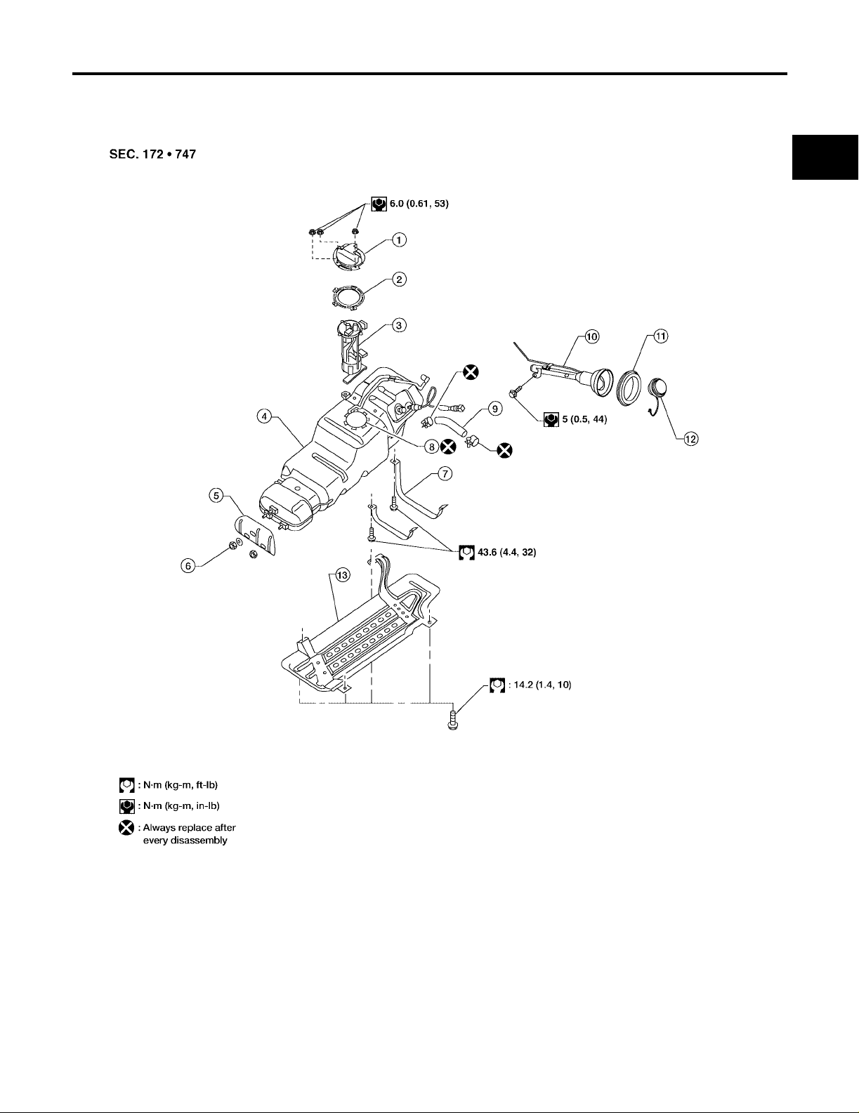
Removal and Installation
EBS00I04
A
FL
C
D
E
F
G
LBIA0420E
1. Fuel line pump protector 2. Lock ring 3. Fuel level sensor, fuel filter, and fuel
pump assembly
4. Fuel tank 5. Fuel tank protector 6. Fuel tank protector clips
7. Fuel tank straps 8. Fuel level sensor, fuel filter, and fuel
pump assembly O-ring
10. Fuel filler pipe 11. Fuel filler hose grommet 12. Fuel filler cap
13. Fuel tank shield
9. Fuel filler hose
H
I
J
K
L
M
Revision: April 2004 2004 Titan
FL-5
Page 6

FUEL LEVEL SENSOR UNIT, FUEL FILTER AND FUEL PUMP ASSEMBLY
REMOVAL
WARNING:
Follow the “Genera l Precautio ns” befor e working o n the f uel syste m. Refer to FL-3, "
tions" .
1. Remove the fuel filler cap to release the pressure from inside the fuel tank.
2. Check the fuel level on level gauge. If the fuel gauge indicates
more than the level as shown (full or almost full), drain the fuel
from the fuel tank until the fuel gauge indicates the level as
shown, or less.
● If the fuel pump does not operate, use the following procedure
to drain the fuel to the specified level.
a. Insert a suitable hose of less than 15 mm (0.59 in) diameter into
the fuel filler pipe through the fue l filler o pening to drain the fue l
from fuel filler pipe.
b. Remove the LH rear wheel and tire. Refer to WT-6, "
Rotation" .
c. Disconnect the fuel filler hose from the fuel filler pipe.
General Precau-
WBIA0390E
LBIA0386E
d. Insert a suitable hose into the fuel tank through the fuel filler hose to drain the fuel from the fuel tank.
● As a guide , the fuel level reaches th e fuel gauge position as shown, or less, when appro ximately 14
liters (3 3/4 U S gal, 3 1/8 Imp gal) of fuel are drained from the fuel tank when it is full.
3. Release the fuel pressure from the fuel lines. Refer to EC-46, "
FUEL PRESSURE RELEASE" .
4. Remove the three nuts and remove fuel line pump protector.
5. Disconnect the EVAP hose at the EVAP canister.
LBIA0405E
6. Disconnect the fuel level sensor, fuel filter, and fuel pump
assembly electrical connector and the fuel feed hose.
Revision: April 2004
FL-6
LBIA0406E
2004 Titan
Page 7

FUEL LEVEL SENSOR UNIT, FUEL FILTER AND FUEL PUMP ASSEMBLY
Disconnect the quick connector as follows:
● Hold the si des of the conn ector, push in tabs and pull out the
tube.
● If the connector and the tube are stuck together, push and pull
several times un til they start to mov e. Then discon nect them
by pulling.
CAUTION:
● The quic k connector can b e disconnec ted when the tabs
are completely depressed. Do not twist the quick connector more than necessary.
● Do not use any tools to disconnect the quick connector.
● Keep the resin tube away from heat. Be especially careful
when welding near the tube.
● Prevent any acid liquids such as battery electrolyte, from
getting on the resin tube.
● Do not bend or twist the resin tube during connection.
● Do not remove the remaining retainer on the hard tube (or
the equivalent) except when the resin tube or the retainer
is replaced.
● When the resin tube or hard tube, or the equivalent, is
replaced, also replace the retainer with a new one (white
colored retainer).
SFE562A
A
FL
C
D
E
F
G
H
I
● To keep the quick connector clean and to avoid damage
and contamination from foreign materials, cover the
quick connector w ith plastic ba gs or suitable material as
shown.
J
K
PBIC1268E
L
M
PBIC0163E
Revision: April 2004 2004 Titan
FL-7
Page 8

FUEL LEVEL SENSOR UNIT, FUEL FILTER AND FUEL PUMP ASSEMBLY
7. Remove the fuel tank strap bolts while supporting the fuel tank
with a suitable lift jack.
8. Lower the fuel tank using a suitable lift jack and remove it from
the vehicle to access the fuel level sensor, fuel filter, and fuel
pump assembly.
9. Remove the lock ring using Tool as shown.
Tool number : — (J-46536)
10. Remove the fuel leve l sensor, fuel filter, and fuel pump assembly. Remove an d d is car d the f u el le vel se ns or, fu el fi l ter, a nd fuel
pump assembly O-r ing.
CAUTION:
● Do not bend the float arm during removal.
● Avoid impacts such as dropping when handling the com-
ponents.
LBIA0387E
LBIA0407E
INSTALLATION
Installation is in the reverse order of removal.
● For installation, use a new fuel level sensor, fuel filter, and fuel pump assembly O-ring.
● Connect the quick connector as follows:
– Check the connection for any damage or foreign materials.
– Align the connector with the pipe, then insert the conn ector straigh t into the pipe until a click is heard.
– After connecting the quick connector, make sure that the con-
nection is secure by checking as follows:
– Pull the tube and th e connec tor to make sure they are secu rely
connected.
– Visually inspect the connector to make sure the two retainer tabs
are securely connected.
PBIC1653E
INSPECTION AFTER INSTALLATION
1. Turn the ignition switch ON but do not start engine, then check the fuel pipes and hose connections for
leaks while applyin g fue l pre ss ure to the sys tem .
2. Start the engine and rev it above idle speed, then check that t here are no fuel leaks at any of the fuel pipe
and hose connecti on s.
Revision: April 2004
FL-8
2004 Titan
Page 9

FUEL TANK
FUEL TANK PFP:17202
Removal and Installation
EBS00I05
A
FL
C
D
E
F
G
LBIA0420E
1. Fuel line pump protector 2. Lock ring 3. Fuel level sensor, fuel filter, and fuel
pump assembly
4. Fuel tank 5. Fuel tank protector 6. Fuel tank protector clips
7. Fuel tank straps 8. Fuel level sensor, fuel filter, and fuel
pump assembly O-ring
10. Fuel filler pipe 11. Fuel filler hose grommet 12. Fuel filler cap
13. Fuel tank shield
9. Fuel filler hose
H
I
J
K
L
M
Revision: April 2004 2004 Titan
FL-9
Page 10

FUEL TANK
REMOVAL
WARNING:
Follow the “Genera l Precautio ns” befor e working o n the f uel syste m. Refer to FL-3, "
tions" .
1. Drain the fuel from the fuel tank, if necessary.
● Position the vehicle so it is level.
2. Remove the fuel filler cap to release the pressure from inside the fuel tank.
3. Check the fuel level on level gauge. If the fuel gauge indicates
more than the level as shown (full or almost full), drain the fuel
from the fuel tank until the fuel gauge indicates the level as
shown, or less.
● If the fuel pump does not operate, use the following procedure
to drain the fuel to the specified level after discon necting the
fuel filler hose from the fuel filler pipe.
a. Insert a suitable hose of less than 15 mm (0.59 in) diameter into
the fuel filler pipe through the fue l filler o pening to drain the fue l
from fuel filler pipe.
b. Insert a suitable hose into the fuel tank through the fuel filler
hose to drain the fuel from the fuel tank.
● As a guide , the fuel level reaches th e fuel gauge position as shown, or less, when appro ximately 14
liters (3 3/4 U S gal, 3 1/8 Imp gal) of fuel are drained from the fuel tank.
General Precau-
WBIA0390E
4. Remove the LH rear wheel and tire. Refer to WT-6, "
Rotation" .
5. Disconnect the fuel filler hose from the fuel filler pipe and disconnect the vent hose quick conn ector.
6. Release the fuel pressure from the fuel lines. Refer to EC-46, "
7. Remove the three nuts and remove fuel line pump protector.
8. Disconnect the EVAP hose at the EVAP canister.
LBIA0386E
FUEL PRESSURE RELEASE" .
Revision: April 2004
FL-10
LBIA0405E
2004 Titan
Page 11

FUEL TANK
9. Disconnect the fuel level sensor, fuel filter, and fuel pump
assembly electrical connector , and the fuel feed hose.
Disconnect the quick connector as follows:
● Hold the si des of the conn ector, push in tabs and pull out the
tube.
● If the connector and the tube are stuck together, push and pull
several times un til they start to mov e. Then discon nect them
by pulling.
A
FL
C
LBIA0406E
D
E
F
G
SFE562A
CAUTION:
● The quic k connector can b e disconnec ted when the tabs
are completely depressed. Do not twist the quick connector more than necessary.
● Do not use any tools to disconnect the quick connector.
● Keep the resin tube away from heat. Be especially careful
when welding near the tube.
● Prevent any acid liquids such as battery electrolyte, from
getting on the resin tube.
● Do not bend or twist the resin tube during connection.
● Do not remove the remaining retainer on the hard tube (or
the equivalent) except when the resin tube or the retainer
is replaced.
● When the resin tube or hard tube, or the equivalent, is
replaced, also replace the retainer with a new one (white
colored retainer).
H
I
J
K
L
M
PBIC1268E
Revision: April 2004 2004 Titan
FL-11
Page 12

FUEL TANK
● To keep the quick connector clean and to avoid damage
and contamination from foreign materials, cover the
quick connector with plastic bags or s uitable material as
shown.
10. Remove the four bolts and remove the fuel tan k shield using po wer tool.
11. Remove the th ree cl i ps an d r e move t he fu el t a nk pro te ct o r at t he
front of the fuel tank as necessary to transfer to the new fuel
tank.
PBIC0163E
12. Disconnect fuel filler hose at t h e fuel tank side.
13. Remove the fuel tank strap bolts while supporting the fuel tank
with a suitable lift jack.
14. Lower the fuel tank using a suitable lift jack and remove it from
the vehicle.
15. If necessary, remove the lock ring using Tool as shown.
Tool number : — (J-46536)
16. If necessary, remove the fuel level sensor, fuel filter, and fuel
pump assembly. Discard the fuel level senso r, fuel filter, and fuel
pump assembly O-r ing.
CAUTION:
● Do not bend the float arm during removal.
● Avoid impacts such as dropping when handling the com-
ponents.
LBIA0388E
LBIA0387E
LBIA0407E
INSTALLATION
Installation is in the reverse order of removal.
● For installation, use a new fuel level sensor, fuel filter, and fuel pump assembly O-ring.
● Connect the quick connector as follows:
– Check the connection for any damage or foreign materials.
– Align the connector with the pipe, then insert the conn ector straigh t into the pipe until a click is heard.
Revision: April 2004
FL-12
2004 Titan
Page 13

FUEL TANK
– After connecti ng the quick connector, make sure that the con -
nection is secure by checking as follows:
– Pull the tube and the con nector to make sure t hey are sec urely
connected.
– Visually inspect the connector to make sure the two retainer tabs
are securely connected.
PBIC1653E
INSPECTION AFTER INSTALLATION
1. Turn the ignition switch ON but do not start engine, then check the fuel pipe and hose connections for
leaks while applying fuel pre ssure.
2. Start the engine and rev i t above id le, then ch eck that th ere are no fu el leaks at any of th e fuel pipe and
hose connections.
A
FL
C
D
E
F
G
H
K
M
I
J
L
Revision: April 2004 2004 Titan
FL-13
Page 14

SERVICE DATA AND SPECIFICATIONS (SDS)
SERVICE DATA AND SPECIFICATIONS (SDS) PFP:00030 Standard and Limit
Fuel tank capacity
EBS00I06
105.8 (28 US gal, 23 1/4 Imp gal)
Revision: April 2004
FL-14
2004 Titan
 Loading...