

Page 1
Owner’s Manual
For professional use only
Do not use this equipment before reading this manual!
ProFinish C-100
Model Number 773-950
Printed in the U. S. A.
NOTE: This manual contains important warnings
and instructions. Please read and retain for
reference.
0900 © 2000 Titan Tool Inc. All rights reserved. Form No. 313-1511, REV B
Page 2
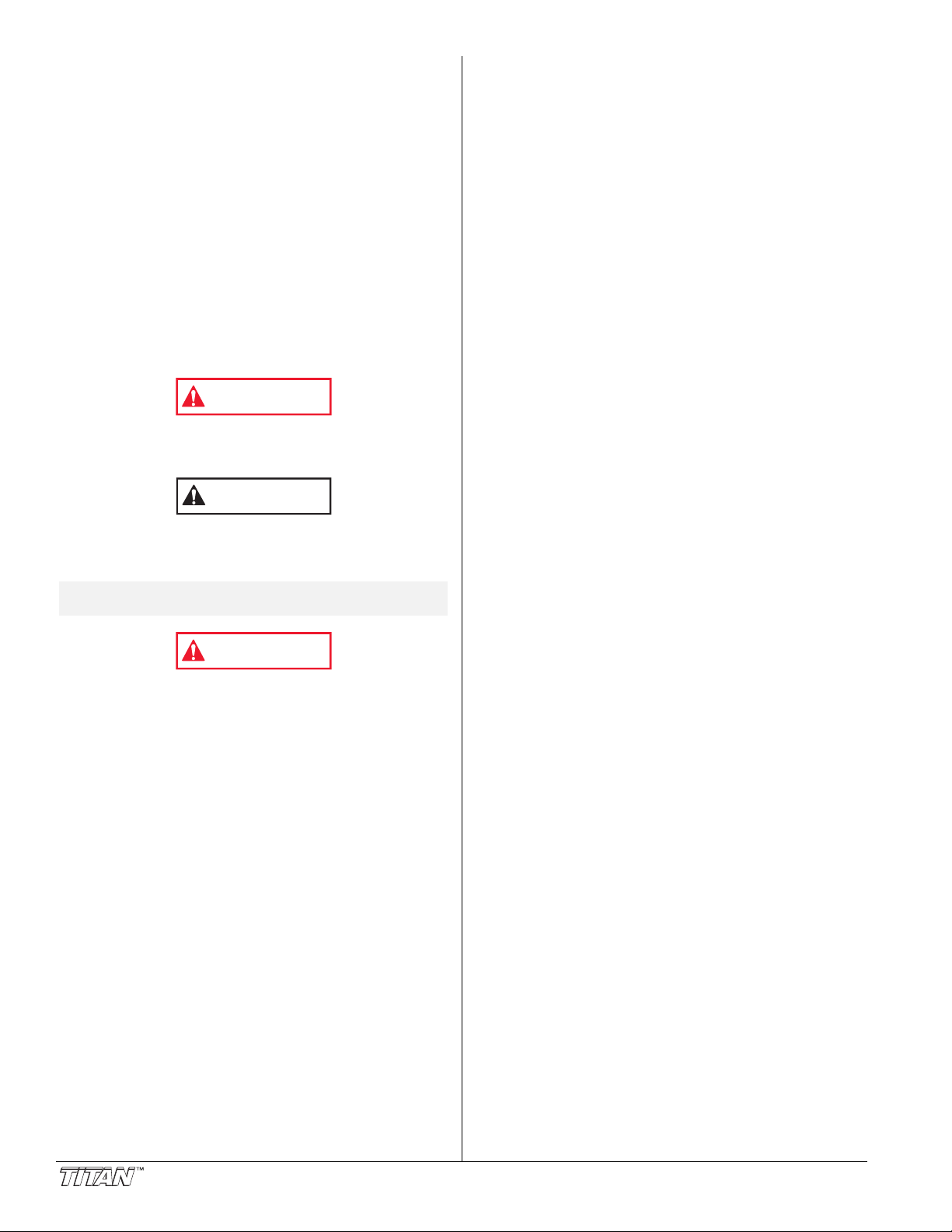
Table of Contents
WARNING
CAUTION
WARNING
Safety . . . . . . . . . . . . . . . . . . . . . . . . . . . . . . . . . . . . . . . . . 2
Français . . . . . . . . . . . . . . . . . . . . . . . . . . . . . . . . . . . . . . 5
Español. . . . . . . . . . . . . . . . . . . . . . . . . . . . . . . . . . . . . . . 7
Introduction. . . . . . . . . . . . . . . . . . . . . . . . . . . . . . . . . . . . . 3
Setup . . . . . . . . . . . . . . . . . . . . . . . . . . . . . . . . . . . . . . . . . . 4
Connecting the Spray System . . . . . . . . . . . . . . . . . . . . . . 4
Operation . . . . . . . . . . . . . . . . . . . . . . . . . . . . . . . . . . . . . . 4
Startup . . . . . . . . . . . . . . . . . . . . . . . . . . . . . . . . . . . . . . . 4
Shutdown . . . . . . . . . . . . . . . . . . . . . . . . . . . . . . . . . . . . . 4
Spray Charts . . . . . . . . . . . . . . . . . . . . . . . . . . . . . . . . . . . . 5
Parts List . . . . . . . . . . . . . . . . . . . . . . . . . . . . . . . . . . . . 9–10
Main Assembly . . . . . . . . . . . . . . . . . . . . . . . . . . . . . . . . . 9
Cart Assembly. . . . . . . . . . . . . . . . . . . . . . . . . . . . . . . . . 10
Warranty . . . . . . . . . . . . . . . . . . . . . . . . . . . . . . . . . . . . . . 12
Safety
This manual contains information that must be read and
understood before using the equipment. When you come to
an area that has one of the following symbols, pay particular
attention and make certain to heed the safeguard.
This symbol indicates a potential hazard that may cause
serious injury or loss of life. Important safety information will
follow.
This symbol indicates a potential hazard to you or to the
equipment. Important information that tells how to prevent
damage to the equipment or how to avoid causes of minor
injuries will follow.
NOTE: Notes give important information that should
be given special attention.
HAZARD: EXPLOSION OR FIRE - Solvent and paint fumes
can explode or ignite. Severe injury and/or
property damage can occur.
PREVENTION:
• Provide extensive exhaust and fresh air introduction to
keep the air within the spray area free from accumulation
of flammable vapors.
• Avoid all ignition sources such as static electric sparks,
open flames, pilot lights, and hot objects. Connecting or
disconnecting power cords or working light switches can
make sparks.
• Do not smoke in spray area.
• Fire extinguisher must be present and in good working
order.
• Place spray system at a minimum of 3 feet (preferably
more) into a separate, well ventilated room from the spray
object or at least 20 feet from the spray object in a well
ventilated area. Flammable vapors are often heavier than
air. Floor area must be extremely well ventilated. The
spray system contains arcing parts that emit spark and
can ignite vapors.
• Follow the material and solvent manufacturer's warnings
and instructions.
• Use extreme caution when using materials with a
flashpoint below 70° F (21° C). Flashpoint is the
temperature that a fluid can produce enough vapors to
ignite.
• Plastic can cause static sparks. Never hang plastic to
enclose a spray area. Do not use plastic drop cloths
when spraying flammable materials.
HAZARD: EXPLOSION HAZARD DUE TO INCOMPATIBLE
MATERIALS - Will cause severe injury or
property damage.
PREVENTION:
• Do not use materials containing bleach or chlorine.
• Do not use halogenated hydrocarbon solvents such as
mildewcide, methylene chloride and 1,1,1 trichloroethane. They are not compatible with aluminum.
• Contact your coating supplier about the compatibility of
material with aluminum.
HAZARD: HAZARDOUS VAPORS - Paints, solvents,
insecticides, and other materials can be harmful if
inhaled or come in contact with the body. Vapors
can cause severe nausea, fainting, or poisoning.
PREVENTION:
• Use a respirator or mask if vapors can be inhaled. Read
all instructions supplied with the mask to be sure it will
provide the necessary protection.
• Wear protective eyewear.
• Wear protective clothing as required by coating manufacturer.
HAZARD: SKIN BURN INJURY— Heated parts can cause
severe skin burn injury.
PREVENTION:
• Quick-disconnect fittings on the hose and the spray gun
become hot during use. Avoid skin contact with any
quick-disconnect fittings when they are hot. Allow the
quick disconnect fittings to cool before disconnecting the
spray gun from the hose
• The compressor becomes hot during use. Allow the
compressor to cool before touching it.
HAZARD: GENERAL - This product can cause severe
injury or property damage.
PREVENTION:
• Read all instructions and safety precautions before
operating equipment.
• Always disconnect the motor from the power supply
before working on the equipment.
• Follow all appropriate local, state, and national codes
governing ventilation, fire prevention, and operation.
• The United States Government Safety Standards have
been adopted under the Occupational Safety and Health
Act (OSHA). These standards, particularly part 1910 of
the General Standards and part 1926 of the Construction
Standards should be consulted.
• Use only manufacturer authorized parts. User assumes
all risks and liabilities when using parts that do not meet
the minimum specifications and safety devices of the
manufacturer.
• Power cord must be connected to a grounded circuit.
• Before each use, check all hoses for cuts, leaks, abrasion
or bulging of cover. Check for damage or movement of
couplings. Immediately replace the hose if any of these
conditions exist. Never repair a hose. Replace it with an
identical replacement hose.
• Do not spray outdoors on windy days.
• Wear clothing to keep paint off skin and hair.
• Never aim spray gun at any part of the body.
HAZARD: EXPLOSION — Compressed air has great force
and may cause injury.
PREVENTION:
• The maximum operating range of the unit is 125 PSI air
pressure.
• The pressure pot assembly is protected from overpressurizing by a safety valve. Pull the ring on the safety
valve occasionally to make sure that the valve operates
freely. The valve must be replaced if it does not operate
freely or if it does not release air when the ring is pulled.
• Never modify the pressure pot or the compressor.
• All accessories must be rated at or above 125 PSI. This
includes spray tips, guns, extensions, hoses, and other tools.
2 © Titan Tool Inc. All rights reserved.
Page 3
Grounding Instructions
Grounded Outlet
Grounding Pin
Tab for
Grounding Screw
Adapter
Metal Screw
Cover for grounded outlet box
This product must be grounded. In the event of an electrical
short circuit, grounding reduces the risk of electric shock by
providing an escape wire for the electric current. This product
is equipped with a cord having a grounding wire with an
appropriate grounding plug. The plug must be plugged into an
outlet that is properly installed and grounded in accordance
with all local codes and ordinances.
DANGER — Improper installation of the grounding plug can
result in a risk of electric shock. If repair or replacement of the
cord or plug is necessary, do not connect the green grounding
wire to either flat blade terminal. The wire with insulation
having a green outer surface with or without yellow stripes is
the grounding wire and must be connected to the grounding
pin.
Check with a qualified electrician or serviceman if the
grounding instructions are not completely understood, or if you
are in doubt as to whether the product is properly grounded.
Do not modify the plug provided. If the plug will not fit the
outlet, have the proper outlet installed by a qualified
electrician.
This product is for use on a nominal 120 volt circuit and has a
grounding plug that looks like the plug illustrated below. A
temporary adapter which looks like the adapter illustrated in
the figure below may be used to connect this plug to a 2 pole
receptacle as shown if a properly grounded outlet is not
available.
The temporary adapter should be used only until a properly
grounded outlet as shown below can be installed by a qualified
electrician. The green colored rigid ear, lug, or the grounding
wire extending from the adapter must be connected to a
permanent ground such as a properly grounded outlet box
cover. Whenever the adapter is used, it must be held in place
by a metal screw.
Introduction
The ProFinish C-100 HVLP spray system is designed for use
as a large capacity, fine finish spray painting tool.
Components of the spray system include a compressor, a cart,
a compressor air outlet, a pressure switch, a pressure pot, a
pressure pot air inlet, and a pressure pot material outlet.
Pressure Pot
Air Inlet
Pressure Pot
Compressor
Storage
Tanks
Cart
NOTE: The compressor can be used to supply air for
other air-powered tools. A tee fitting on the
compressor air outlet allows the installation of
an additional regulator.
Pressure Pot
Material Outlet
(behind regulator)
Compressor
Air Outlet
Pressure Switch
CAUTION
Use only a 3-wire extension cord that has a 3-blade
grounding plug and a 3-slot receptacle that will accept the
plug on the product. Make sure your extension cord is in
good condition. When using an extension cord, be sure
to use one heavy enough to carry the current your
product will draw. For lengths less than 25 feet, No. 16
AWG extension cords should be used. Between 25 feet
and 50 feet, the minimum gauge is 12 AWG. An
undersized cord will cause a drop in line voltage resulting
in loss of power and overheating. If an extension cord is
to be used outdoors, it must be marked with the suffix WA after the cord type designation. For example, a
designation of SJTW-A would indicate that the cord would
be appropriate for outdoor use.
© Titan Tool Inc. All rights reserved. 3
Page 4
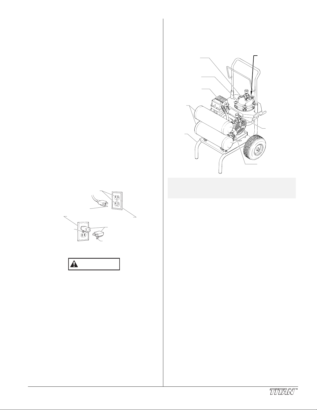
Setup
Pressure Pot Outlet
Material Hose
Air Hose
Spray Gun
Material
Inlet
Spray Gun
Air Inlet
Compressor
Air Outlet
Pressure
Control Knob
Pressure Gauge
Cover
Groove
Seal
Locking Clamp
Pressure Pot
Pressure
Control Knob
Pot Liner
(optional)
Operation
Connecting the Spray System
1. Make sure the ON/OFF lever on the pressure switch is on
the OFF position.
2. Connect the compressor hose from the lower storage tank
to the pressure pot air inlet.
NOTE: The hose features quick-disconnect fittings.
To use, pull back on the spring-loaded collar
of each fitting. Slide the hose fitting over the
correct connection and release the collar.
Pressure Pot Air Inlet
Compressor Hose
3. Thread the end of the material hose onto the pressure pot
material outlet and tighten.
4. Thread the other end of the material hose onto the spray
gun material inlet and tighten.
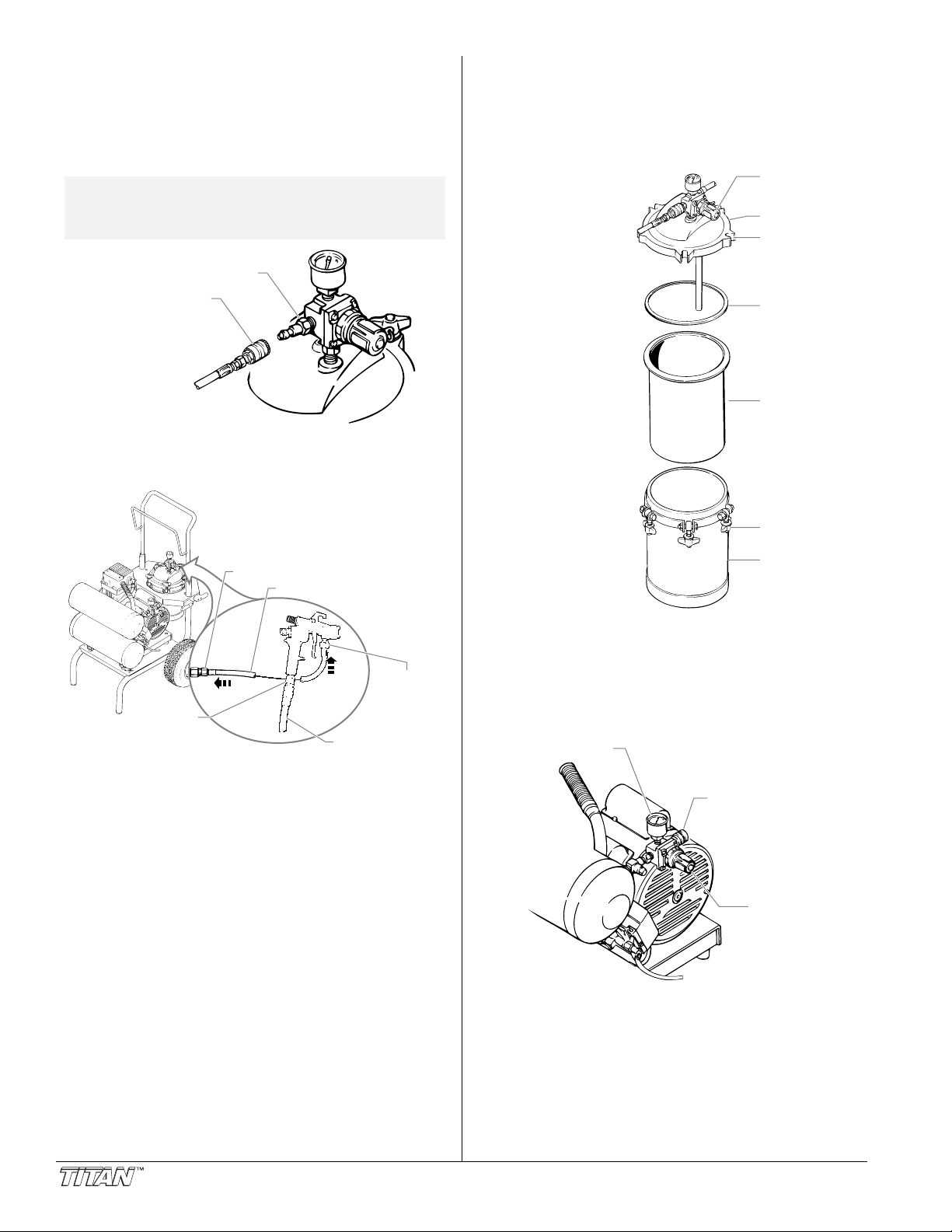
Startup
1. Place the unit in a clean, dry and well-ventilated area.
The compressor should be located at least 12” from walls
or other obstructions that could interfere with the flow of
air.
2. Fill the pressure pot
with spray material.
3. Fasten the cover
securely onto the
pressure pot by
placing the five
locking clamps into
the cover grooves
and rotating each
clockwise until hand
tight. Be certain that
the seal is in place.
4. Plug in the power
cord for the
compressor.
5. Move the ON/OFF
lever on the pressure
switch to the ON
position to start the
compressor. Allow
the tank pressure to
build. When the
motor stops, the
compressor has
reached cut-out
pressure, and the
system is ready for
use.
6. Pull out the pressure
control knob on the
pressure pot and
turn it until the pressure pot pressure is set properly for
the type of material you are using.
• For thin materials, set to 8 PSI.
• For thicker materials, set to between 8 and 14 PSI.
7. Pull out the pressure control knob on the compressor air
outlet and turn it until the gun pressure is set properly for
the type of material you are using (see spray chart for
reference).
5. Connect the air hose to compressor air outlet.
6. Thread the other end of the air hose onto the spray gun
air inlet and tighten.
8. Practice spraying on a piece of scrap wood or cardboard
until you are satisfied with the pot pressure, gun air
pressure, spray pattern, and spray shape. The spray
pattern adjustments and spray shape selections are
described in your gun manual.
Shutdown
1. Move the ON/OFF lever on the pressure switch to the
OFF position.
2. Allow the compressor to cool.
3. Drain the storage tanks (refer to compressor manual for
procedure).
4 © Titan Tool Inc. All rights reserved.
Page 5

Spray Charts
Spraying Pressure Air Consumption
Pressure
Inside Cap
Compressor Pressure*
Air CFM
6 PSI 6.5 9
15
18
20
24
7.5
7.8
8
8.5
8 PSI
10 PSI
12 PSI
14 PSI
*The pressure at the compressor air outlet
when spraying gun.
Français
Sécurité
AVERTISSEMENT
© Titan Tool Inc. All rights reserved. 5
DANGER: RISQUES D'EXPLOSION OU D'INCENDIE - Les
vapeurs dégagées par le solvant ou la peinture
sont explosives et inflammables et peuvent
causer des corporels sérieux ou dommages
matériels.
MESURES PRÉVENTIVES:
• Veiller à éviter toute accumulation de vapeurs
inflammables en vous assurant que la zone où la
pulvérisation a lieu est suffisamment ventilée.
• Veiller à éviter la présence de toute source incandescente
telle qu'étincelle électrostatique, flamme nue, flammepilote, objet brûlant, cigarette et étincelle provenant du
branchement ou du débranchement d'un cordon
d'alimentation électrique ou d'un commutateur.
• Ne pas fumer dans la zone d’épandage.
• Toujours avoir un extincteur en état de fonctionner à
portée de la main.
• Placer la pompe à peinture à une distance d’au moins un
mètre (3 pi) (on recommande d’ailleurs une plus grande
distance) de l’objet qui doit être vaporisé dans une pièce
séparée bien aérée, ou à une distance d’au moins six
mètres (20 pi) de celui-ci dans une zone bien aérée. Les
vapeurs inflammables sont souvent plus lourdes que l’air.
Le plancher doit être extrêmement bien aéré. La pompe à
peinture contient des pièces pouvant créer des étincelles
et enflammer les vapeurs présentes dans l’air.
• Se conformer aux consignes et recommandations de
sécurité du fabricant du solvant ou du produit.
• S’entourer de toutes les précautions possibles lorsqu’on
utilise des produits ayant un point d’éclair inférieur à 21
°C (70 °F). Le point d’éclair d’un fluide est la température
à laquelle les vapeurs émanant du fluide peuvent
s’enflammer au contact d’une flamme ou d’une étincelle.
• Le plastique peut être une source d’étincelles provoquées
par l’électricité statique. Ne jamais utiliser une couverture
en plastique pour fermer une zone d’épandage ni utiliser
des toiles de protection en plastique lors de la
pulvérisation de matières inflammables.
DANGER: RISQUES D'EXPLOSION PAR
INCOMPATIBILITÉ DES MATÉRIAUX - Peuvent
être à l'origine de corporels sérieux ou
dommages matériels.
MESURES PRÉVENTIVES:
• Ne pas utiliser de matériaux contenant des agents de
blanchiment ou du chlore.
• Ne pas utiliser des solvants à base d’hydrocarbure
halogéné tels que l’agent anticryptogamique, le chlorure
de méthylène et le trichloro-éthane-1,1,1. Ces produits ne
sont pas compatibles avec l’aluminium
• Communiquer avec votre fournisseur de revêtement pour
connaître la compatibilité du matériau avec l’aluminium.
DANGER: VAPEURS NOCIVES – la peinture, les solvants,
les insecticides et autres matériaux peuvent
être nocifs lorsqu’ils sont inhalés ou en
contact avec le corps. Les vapeurs peuvent
causer une nausée importante, des
évanouissements ou un empoisonnement.
MESURES PRÉVENTIVES:
• Utiliser un respirateur ou un masque chaque fois qu'il y a
des risques d'inhalation de vapeurs. Lire attentivement
toutes les instructions se rapportant au masque pour
vérifier que celui-ci vous assure une protection suffisante
contre les vapeurs toxiques.
• Porter des lunettes de protection.
• Porter des vêtements de protection, conformément aux
directives du fabricant de revêtement.
Page 6

DANGER: DANGER DE BRÛLURE — Les pièces
Prise de terre
Goupille de mise la terre
Patte pour
vis de mise
la terre
Adapteur
Vis m tallique
Couvercle du bo tier de prise de terre
chauffées peuvent causer de graves brûlures
cutanées.
PRÉVENTION:
• Les raccords à dégagement rapide du tuyau flexible et du
pistolet peuvent s'échauffer en cours d'utilisation; il faut
alors éviter les contacts cutanés, en attendant que les
raccords refroidissent avant de séparer le pistolet du
tuyau.
• Le compresseur devient chaud à l'utilisation. Le laisser
refroidir avant d'y toucher.
DANGER: GÉNÉRALITÉS - Peut causer des dommages
matériels ou corporels sérieux.
MESURES PRÉVENTIVES:
• Avant d'utiliser tout équipement, lire attentivement toutes
les instructions et les consignes de sécurité
• Toujours débrancher le moteur de l’alimentation électrique
avant d’effectuer des travaux sur l’appareil.
• Se conformer à la législation locale, provinciale ou fédérale
pour tout ce qui concerne la ventilation, la prévention des
incendies et les conditions générales d'utilisation.
• Les normes de sécurité du Gouvernement américain sont
régies par le Occupational Safety and Health Act (OSHA).
Il est important de consulter ces normes, en particulier la
section 1910 sur le normes générales et la section 1926
sur les des normes de la construction.
• N’utiliser que les pièces autorisées par le fabricant.
L’utilisateur assume tous les risques et responsabilités
lorsqu’il utilise des pièces qui ne sont pas conformes aux
caractéristiques techniques minimales ainsi qu’aux
dispositifs de sécurité du fabricant.
• Le cordon d’alimentation doit être raccordé à un circuit
mis à la terre.
• Vérifier, avant toute utilisation, que les flexibles ne
présentent pas d'entaille ou de fuite, que le couvercle ne
soit pas gonflé et que les raccords ne soient pas
endommagés. Si le flexible a subi l'un des dommages
précités, remplacez-le immédiatement. Ne jamais réparer
un flexible d'alimentation. Le remplacer avec un flexible
identique de remplacement.
• Ne jamais pulvériser lorsqu'il vente.
• Porter des vêtements pour protéger la peau et les
cheveux contre tout contact avec la peinture.
• NE JAMAIS diriger le pistolet vers une quelconque partie
du corps.
DANGER: EXPLOSION — L'air comprimé est très
puissant et peut provoquer des blessures.
PREVENTION:
• L'ensemble réservoir est protégé contre la surpression par
une soupape de sécurité. De temps en temps, tirer sur
l'anneau de la soupape de sécurité pour vérifier qu'elle
fonctionne normalement. Remplacer la soupape si elle ne
fonctionne pas bien ou si elle ne laisse pas passer l'air
quand on tire sur l'anneau.
• Ne jamais modifier le réservoir sous pression ni le
compresseur.
• Ne connecter aucun autre outil pneumatique au
compresseur.
Instructions de mise à la terre
Cet appareil doit être mis à la terre. La mise à la terre réduit
les risques d'électrocution lors d'un court-circuit en permettant
au courant de s'écouler par le fil de mise à la terre. Cet
appareil est muni d'un cordon électrique avec fil de mise à la
terre ainsi que d'une fiche de terre. La fiche doit être branchée
sur une prise installée correctement et mise à la terre
conformément à la réglementation et aux codes en vigueur.
DANGER — Une prise de terre mal branchée peut être à
l'origine d'électrocutions. S'il s'avère nécessaire de réparer ou
de remplacer le cordon électrique ou la fiche, ne pas brancher le
fil vert de mise à la terre sur l'une ou l'autre des bornes à broche
plate. Le fil recouvert d'un isolant vert avec ou sans rayures
jaunes est le fil de mise à la terre et doit être branché sur la
broche de mise à la terre.
Si vous ne comprenez pas les instructions de mise à la terre
ou si vous n'êtes pas sûr que l'appareil est correctement mis à
la terre, contactez un électricien agréé. Ne pas modifier la
fiche d'origine. Si la prise ne convient pas à la fiche, faites
installer la prise adéquate par un électricien agréé.
Cet appareil est conçu pour un tension normale de 120 V et
est muni d'une fiche de mise à la terre semblable à celle de
l'illustration ci-dessous. Un adaptateur temporaire semblable à
celui illustré à la figure ci-dessous, peut être utilisé pour
raccorder cette fiche dans une prise bipolaire, tel qu’illustré,
lorsqu’une prise de courant avec contact de mise à la terre
n’est pas disponible.
L’adaptateur temporaire doit être utilisé seulement jusqu’à ce
qu’une prise de courant avec contact de mise à la terre, tel
qu’illustré ci-dessous, puisse être installée par un électricien
qualifié. L’oreillette de fixation rigide de couleur verte ou le fil
de mise à la terre raccordé à l’adaptateur doit être mis à la
terre en permanence, par l’entremise d’un composant
quelconque, tel qu’une boîte de sortie. Lorsque l’adaptateur
est utilisé, il doit être tenu en place au moyen d’une vis
métallique.
ATTENTION
Utiliser uniquement une rallonge à trois fils munie d'une
fiche de terre dans une prise secteur mise à la terre
correspondant au type de fiche de l'appareil. S'assurer
que votre rallonge est en bon état. Lorsque vous utilisez
une rallonge, assurez-vous qu'elle soit d'un calibre
suffisant pour supporter l'intensité du courant requise par
l'appareil. Pour des longueurs moins que 25 pieds, No.
16 AWG rallonge devraient être employées. Entre 25 et 50
pieds, de calibre minimum est 12 AWG. Une rallonge trop
mince entraîne une chute de tension, une diminution de
l'intensité et une surchauffe. Si vous devez utiliser une
rallonge à l’extérieur, celle-ci doit comprendre la marque
W-A après la désignation indiquant le type de cordon. Par
exemple, la désignation SJTW-A indique que le cordon est
conçu pour être utilisé à l’extérieur.
6 © Titan Tool Inc. All rights reserved.
Page 7

Español
Seguridad
ADVERTENCIA
PELIGRO: EXPLOSIÓN O INCENDIO - Los vapores de
solventes y pintura pueden explotar o
incendiarse, causando con esto lesiones
severas y/o daños en la propiedad.
PARA PREVENIR:
• Debe proveerse un escape y aire fresco para hacer que el
aire que está dentro del área de atomización se mantenga
libre de acumulaciones de vapores inflamables.
• Evite todas las fuentes de ignición como son las chispas
electrostáticas, llamas abiertas, flamas de piloto, objetos
calientes, cigarros, y chispas que se generan al conectar
y desconectar las extensiones o de apagadores de luz
que estén funcionando.
• No fume en la zona de trabajo.
• Debe haber un equipo para extinguir incendios
permanentemente y en buenas condiciones.
• Coloque la bomba para pintar a un mínimo de 1 m (de
preferencia más) en una habitación aparte, bien ventilada,
alejada del objeto que va a pintar o a por lo menos 6 m
de dicho objeto, en una zona bien ventilada (utilice una
manguera más larga, si es necesario). Los gases
inflamables a menudo son más pesados que el aire. La
zona del piso debe tener la debida ventilación. La bomba
para pintar contiene piezas que forman arcos que emiten
chispas y pueden encender los gases.
• Siga las advertencias y avisos de seguridad del fabricante
de los materiales y solventes.
• Tenga muchísimo cuidado al usar materiales cuyo punto
de ignición sea inferior a 70° F (21° C). El punto de
ignición es la temperatura a la cual pueden encenderse
los vapores emanados por un fluido al exponerlos a
llamas o chispas.
• El plástico puede causar chispas estáticas. Nunca
cuelgue plástico en las ventanas ni en las puertas del
área donde va a pintar. No utilice plástico para proteger
el piso cuando pinte materiales inflamables.
PELIGRO: PELIGRO DE EXPLOSIÓN DEBIDO A
MATERIALES INCOMPATIBLES - Podría
causar lesiones severas o daños en la
propiedad.
PARA PREVENIR:
• No utilice materiales que contengan blanqueador o cloro.
• No use solventes con hidrocarburos halogenados, tales
como productos para eliminar el moho, cloruro de
metileno y 1,1,1 - tricloroetano. Estos no son compatibles
con el aluminio.
• Comuníquese con el proveedor del producto para obtener
información de compatibilidad con materiales de aluminio.
PELIGRO: GASES PELIGROSOS - Las pinturas, solventes,
insecticidas y otros materiales pueden ser
perjudiciales si se inhalan o entran en contacto
con el cuerpo. Los gases pueden causar
náusea, desmayos o envenenamiento graves.
PARA PREVENIR:
• Use una mascarilla respiratoria o careta siempre que
exista la posibilidad de que se puedan inhalar vapores.
Lea todas las intrucciones que vengan con la careta para
estar seguro de que se tendrá la protección necesaria
contra la inhalación de vapores dañinos.
• Use gafas protectoras.
• Use ropa de protección, según lo requiera el fabricante
del producto.
PELIGRO: QUEMADURA DE LA PIEL — Las piezas
calientes pueden causar lesiones de
quemadura de la piel severas.
PREVENCIÓN:
• Las conexiones de desconexión rápida de la manguera y
la pistola de atomización se llegan a calentar mientras se
usan. Evite que la piel tenga contacto con las conexiones
de desconexión rápida cuando se calienten. Deje que las
conexiones de desconexión rápida se enfríen antes de
desconectar la pistola de atomización de la manguera.
• El compresor se calienta durante el uso. Permita que el
compresor se enfríe antes de tocarlo.
PELIGRO: GENERAL - Puede causar daños en la
propiedad o lesiones severas.
PARA PREVENIR:
• Lea todas las instrucciones y advertencias de seguridad
antes de hacer funcionar cualquier equipo.
• Desconecte siempre el motor del suministro eléctrico
antes de dar servicio al equipo.
• Observe todos los códigos locales, estatales y nacionales
apropiados que rigen las medidas de ventilación,
prevención de incendios y operación.
• Los Estándares de Seguridad del Gobierno de los
Estados Unidos se han adoptado bajo el Acta de
Seguridad y Salud Ocupacionales (OSHA por sus siglas
en inglés). Deben consultarse estos estándares,
particularmente la parte 1910 de los Estándares
Generales y la parte 1926 de los Estándares de la
Construcción.
• Utilice únicamente piezas autorizadas por el fabricante.
El usuario asume todos los riesgos y responsabilidades si
usa piezas que no cumplen con las especificaciones
mínimas y dispositivos de seguridad del fabricante.
• El cable de alimentación debe enchufarse a un circuito
aterrado.
• Antes de usarla cada vez, revise todas las mangueras para
ver que no tengan cortadas, fugas, una cubierta desgastada
por abrasión o con abolladuras, así como uniones dañadas
o que se hayan movido. Si existiera cualquiera de estas
condiciones, reemplace la manguera inmediatamente. No
repare nunca una manguera. Reemplazar lo con una
manguera idéntica de reemplazo.
• No atomice en días con viento.
• Use ropa que evite el contacto de la pintura con la piel y
el cabello.
• NO dirija NUNCA la punta de la pistola hacia alguna parte
del cuerpo.
PELIGRO: EXPLOSION — El aire comprimido tiene una
gran fuerza y pudiera causar lesiones.
PREVENCION:
• El ensamble del tanque de presión está protegido con una
válvula de seguridad en caso de una sobre presurización.
Ocasionalmente jale la argolla de la válvula de seguridad
para asegurarse que la válvula opere libremente. En caso
de no operar con libertad o si la válvula no libera aire
cuando se jala la argolla, debe cambiarse.
• Nunca modifique el tanque de presión o el compresor.
• Nunca conecte otras herramientas de aire al compresor.
© Titan Tool Inc. All rights reserved. 7
Page 8

Instrucciones para conectar a tierra
PRECAUCION
Este producto se debe conectar a tierra. En caso de que
ocurra un corto circuito, la conexión a tierra reduce el riesgo
de choque eléctrico al proporcionar un alambre de escape
para la corriente eléctrica. Este producto está equipado con
un cable que tiene un alambre de conexión a tierra con un
enchufe de conexión a tierra apropiado. El enchufe se debe
enchufar en una toma de corriente que se haya instalado y
conectado a tierra debidamente, de acuerdo con todos los
códigos y estatutos locales.
PELIGRO — Una instalación inapropiada del enchufe de
conexión a tierra puede dar como resultado el que exista un
riesgo de choque eléctrico. Si es necesario reparar o
reemplazar el cable o el enchufe, no conecte el alambre de
conexión a tierra a ninguno de los terminales de hoja planos.
El alambre con aislamiento que tiene la superficie exterior de
color verde con franjas amarillas o sin ellas es el alambre de
conexión a tierra que debe conectarse al conector de conexión
a tierra.
Verifique con un electricista o técnico de servicio calificado si
las instrucciones para conectar a tierra no le han quedado
completamente claras, o si duda que el producto haya
quedado conectado a tierra de manera apropiada. No
modifique el enchufe que se proporciona. Si el enchufe no
entra en la toma de corriente, pídale a un electricista calificado
que instale la toma apropiada.
Este producto está diseñado para usarse en un circuito de 120
voltios nominales y el enchufe de conexión a tierra que tiene
se parece al enchufe que se ilustra a continuación. Si no
dispone de una toma de corriente con conexión a tierra, puede
usar un adaptador temporal que se asemeja al adaptador
ilustrado en la figura a continuación, para conectar este
enchufe en un receptáculo de 2 polos como se muestra.
El adaptador temporal solamente se debe utilizar hasta que un
electricista calificado instale debidamente una toma de
corriente con conexión a tierra. La patilla verde o alambre de
conexión a tierra que se extiende desde el adaptador se debe
conectar a tierra permanente, tal como la tapa de una caja de
distribución conectada a tierra. Cuando use el adaptador, debe
mantenerlo en su lugar con un tornillo metálico.
Tomacorriente aterrado
Terminal de tierra
Tapa de la caja del tomacorriente aterrado
Tornillo met lico
Use solamente extensiones trifilares que tengan un
enchufe de conexión a tierra de 3 hojas y un receptáculo
de triple ranura que acepte el enchufe del producto.
Asegúrese de que su extensión esté en buenas
condiciones. Cuando use una extensión, asegúrese de
usar una que sea lo suficientemente resistente como para
soportar la corriente que descargue su producto. Para
longitudes menos de 25 los pies, usan únicos un No. 16
AWG cable de extensión. Entre 25 y 50 pies, el calibre
mínimo es 12 AWG. Un cable de un tamaño menor
causará una caída de voltage en la línea que dará como
resultado una pérdida de energía y un sobrecalenta|ôento.
Si se utiliza un cable de extensión en el exterior, tiene que
estar marcado con el sufijo W-A después de la
designación del tipo de cable. Por ejemplo, SJTW-A para
indicar que el cable es apropiado para uso en exteriores.
Adaptador
Lengueta
del tornillo
de conexi n a tierra
8 © Titan Tool Inc. All rights reserved.
Page 9

3
1
2
11
4
7
5
6
8
2
9
10
11
12
13
14
15
16
18
17
19
20
21
To gun
Parts List
Main Assembly
Item Part # Description Quantity
1 773-914 Air hose.................................................1
2 770-543 Fitting, air, 1/4" male, quick connect.....2
3 773-927 Compressor ..........................................1
4 773-910 Cart .......................................................1
5 858-001 Washer..................................................4
6 763-551 Lock washer..........................................4
7 858-625 Screw....................................................4
8 0275640 Coupling, quick connect .......................1
9 770-544 Pressure gauge, 60 psi.........................1
10 227-027 Plug, 1/4” ..............................................1
11 773-937 Regulator ..............................................2
Item
12 770-541 Fitting, 1/4” x 1/8”..................................1
13 0277348 Hose, material (connects to gun) .........1
14 770-576 Valve, relief ...........................................1
15 770-575 Fitting, fluid ...........................................1
16 770-564 Lid .........................................................1
17 770-563 Tube, pick up ........................................1
18 773-760 Pot gasket.............................................1
19 770-535 Pot liner (optional) ................................1
20 773-938 Pot bottom ............................................1
21 773-913 Pressure pot assembly
Part # Description Quantity
(Includes Items 15, 16,17, 18, and 20)...1
© Titan Tool Inc. All rights reserved. 9
Page 10

2
1
3
4
5
6
7
8
10
12
13
14
15
16
17
18
4
5
19
20
21
22
23
24
11
9
Cart Assembly (P/N 773-910)
Item
1 770-708 Hole trim ...............................................1
2 773-902 Platform ................................................1
3 773-917 Screw....................................................4
4 860-004 Washer..................................................6
5 763-549 Nut ........................................................6
6 773-912 Leg, left.................................................1
7 335-018 Plug.......................................................2
8 0508144 Handle ..................................................1
9 590-508 Roll pin..................................................2
10 590-507 Snap button ..........................................2
11 773-918 Screw....................................................2
12 590-504 Sleeve...................................................2
Part #
Description Quantity
Item
13 590-506 Washer..................................................2
14 773-908 Pressure pot holder ..............................1
15 0279437 Cord wrap.............................................2
16 773-921 Screw....................................................4
17 856-921 Screw....................................................4
18 856-002 Washer..................................................4
19 590-203 Axle.......................................................1
20 570-010 Cotter pin ..............................................2
21 773-743 Spacer ..................................................2
22 773-952 Wheel....................................................2
23 870-004 Washer..................................................2
24 773-911 Leg, right...............................................1
Part # Description Quantity
10 © Titan Tool Inc. All rights reserved.
Page 11

Notes
© Titan Tool Inc. All rights reserved. 11
Page 12

Limited Warranty - High Volume, Low Pressure Spray Equipment
What Is Covered By This Warranty:
This product, manufactured by Titan Tool Inc., is warranted against defects in material and workmanship for one (1) year following
date of purchase if operated in accordance with Titan's printed recommendations and instructions.
Within the applicable warranty period, Titan tool Inc. will repair or replace, at our option, defective parts without charge if such
parts are returned with transportation charges prepaid to the nearest Authorized Service Center or to Titan Tool Inc.. If Titan Tool
Inc. is unable to repair this product as to conform to this Limited Warranty after a reasonable number of attempts, Titan Tool Inc.
will provide, at our option, either a replacement for this product or a full refund of the purchase price of this product. These
remedies are the sole and exclusive remedies available for breach of express and implied warranties.
What is Not Covered By This Warranty:
1. This Warranty does not cover any defects or damages caused by either:
a) the use or installation of repair or replacement parts or accessories not manufactured by Titan Tool Inc., or
b) repair performed by anyone other than a Titan Tool Inc. Authorized Service Center.
2. The Warranty does not cover equipment and accessories supplied to Titan Tool Inc. from an original equipment
manufacturer, including but not limited to: hoses, tips, or accessories. Titan Tool Inc. will provide the purchaser with copies of
the original equipment manufacturer’s express warranties provided to Titan Tool Inc. along with the name and address of the
appropriate manufacturer. In the case of the compressor, the manufacturer has extended the warranty — first year for parts
and service, second year on parts only.
3. This Warranty does not cover damage or defects caused by or related to abrasion, corrosion, abuse, misuse, negligence,
accident, normal wear, faulty installation or tampering in a manner which impairs normal operation.
Limitation of Remedies:
IN NO CASE SHALL TITAN TOOL INC. BE LIABLE FOR ANY INCIDENTAL, SPECIAL OR CONSEQUENTIAL DAMAGES OR
LOSS, INCLUDING TRANSPORTATION COSTS, WHETHER SUCH DAMAGES ARE BASED UPON A BREACH OF EXPRESS
OR IMPLIED WARRANTIES, BREACH OF CONTRACT, NEGLIGENCE, STRICT TORT, OR ANY OTHER LEGAL THEORY.
Disclaimer Of Implied Warranties:
THE FOREGOING WARRANTIES ARE IN LIEU OF ALL OTHER WARRANTIES, EXPRESS OR IMPLIED, INCLUDING BUT
NOT LIMITED TO THE IMPLIED WARRANTIES OF MERCHANTABlLlTY AND FITNESS FOR A PARTICULAR PURPOSE.
No Ability To Transfer:
This warranty is extended to the original purchaser only and is not transferable.
Your Rights Under State Law:
Some states do not allow limitations on how long an implied warranty lasts or the exclusion of incidental or consequential
damages, so the above limitation and exclusion may not apply to you. This warranty gives you specific legal rights, and you may
also have other rights which vary from state to state.
National Sales & Service
1-800-526-5362
Fax 1-800-528-4826
556 Commerce Street
Franklin Lakes, NJ 07417
www.titantool.com
Canadian Branch
1-800-565-8665
Fax 1-905-856-8496
200 Trowers Road, Unit 7B
Woodbridge, L4L 5Z8
12 © Titan Tool Inc. All rights reserved.
International
1-201-405-7520
Fax 1-201-405-7449
556 Commerce Street
Franklin Lakes, NJ 07417 USA
www.titan-tools.com
 Loading...