

Page 1
Owner’s Manual
Notice d’utilisation
Manual del Propietario
For professional use only
Do not use this equipment before reading this manual!
640i
Airless Sprayer
Model Number:
Skid Complete 765-3000
High Rider Complete 765-3010
Low Rider Complete 765-3015
Printed in the U. S. A.
NOTE: This manual contains important warnings
NOTE: This manual contains important warnings
0707 © 2003 Titan Tool Inc. All rights reserved. Form No. 313-1633, REV E
and instructions. Please read and retain for
and instructions. Please read and retain for
reference.
reference.
EnglishFrançaisEspañol
Page 2
Important Safety Information • Read all safety information before
operating the equipment. Save these instructions.
This symbol indicates a hazardous situation,
which, if not not avoided could result in death or
serious injury.
To reduce the risks of fire or explosion, electrical
shock and the injury to persons, read and understand all instructions included in this manual. Be
familiar with the controls and proper usage of the
equipment.
HAZARD: INJECTION INJURY
A high pressure paint stream produced by this
equipment can pierce the skin and underlying
tissues, leading to serious injury and possible
amputation. See a physician immediately
DO NOT TREAT AN INJECTION INJURY AS A SIMPLE
CUT! Injection can lead to amputation. See a physician
immediately
The maximum operating range of the sprayer is 3200 PSI / 22.1
MPa fluid pressure.
PREVENTION:
• NEVER aim the gun at any part of the body.
• Do not aim the gun at, or spray any person or animal.
• NEVER allow any part of the body to touch the fluid stream.
DO NOT allow body to touch a leak in the fluid hose.
• NEVER put your hand in front of the gun. Gloves will not
provide protection against an injection injury.
• ALWAYS lock the gun trigger, shut the pump off, and
release all pressure before servicing, cleaning the tip or
guard, changing tip, or leaving unattended. Pressure will
not be released by turning off the motor. The
PRIME/SPRAY valve or pressure bleed valve must be
turned to their appropriate positions to relieve system
pressure. Refer to the PRESSURE RELIEF
PROCEDURE described in this manual.
• ALWAYS keep the tip guard in place while spraying. The
tip guard provides some protection but is mainly a
warning device.
• ALWAYS remove the spray tip before flushing or cleaning
the system.
• Paint hose can develop leaks from wear, kinking and
abuse. A leak can inject material into the skin. Inspect
the hose before each use. Do not use hose to lift or pull
equipment.
• NEVER use a spray gun without a working trigger lock
and trigger guard in place.
• All accessories must be rated at or above 3200 PSI / 22.1
MPa. This includes spray tips, guns, extensions, and hose.
• Do not leave the unit energized or under pressure while
unattended. When the unit is not in use, turn off the unit
and relieve the pressure in accordance with the
PRESSURE RELIEF PROCEDURE described in this
manual.
• Verify that all connections are secure before operating the
unit. Unsecured parts may eject at great force or leak a
high pressure fluid stream causing severe injury.
• Always engage the trigger lock when not spraying. Verify
the trigger lock is functioning properly.
NOTE TO PHYSICIAN:
Injection into the skin is a traumatic injury. It is
important to treat the injury as soon as possible. DO
NOT delay treatment to research toxicity. Toxicity is a
concern with some coatings injected directly into the
blood stream. Consultation with a plastic surgeon or
reconstructive hand surgeon may be advisable.
.
.
HAZARD: HAZARDOUS VAPORS
Paints, solvents, insecticides, and other materials can
be harmful if inhaled or come in contact with the body
Vapors can cause severe nausea, fainting, or
poisoning.
PREVENTION:
• Use a respirator or mask if vapors can be
inhaled. Read all instructions supplied with the
mask to be sure it will provide the necessary
protection.
Wear protective eyewear.
•
• Wear protective clothing as required by coating
manufacturer.
HAZARD: EXPLOSION OR FIRE
Solvent and paint fumes can explode or ignite.
Property damage and/or severe injury can occur
PREVENTION:
• Provide extensive exhaust and fresh air introduction to
keep the air within the spray area free from accumulation
of flammable vapors. Solvent and paint fumes can
explode or ignite.
•
Do not spray in a confined area.
• Avoid all ignition sources such as static electric
sparks, open flames, pilot lights, electrical
appliances, and hot objects. Connecting or disconnecting
power cords or working light switches can make sparks.
Paint or solvent flowing through the equipment is able to
result in static electricity.
• Do not smoke in spray area.
• Fire extinguisher must be present and in good working
order.
• Place pump at least 25 feet (7.62 meters) from the spray
object in a well ventilated area (add more hose if
necessary). Flammable vapors are often heavier than air.
Floor area must be extremely well ventilated. The pump
contains arcing parts that emit sparks and can ignite
vapors.
• The equipment and objects in and around the spray area
must be properly grounded to prevent static sparks.
• Keep area clean and free of paint or solvent containers,
rags and other flammable materials.
• Use only conductive or grounded high pressure fluid hose.
Gun must be grounded through hose connections.
• For electric units — power cord must be connected to a
grounded circuit.
• Always flush unit into a separate metal container, at low
pump pressure, with spray tip removed. Hold gun firmly
against side of container to ground container and prevent
static sparks.
• Follow the material and solvent manufacturer's warnings
and instructions. Know the contents of the paints and
solvents being sprayed. Read all Material Safety Data
Sheets (MSDS) and container labels provided with the
paints and solvents. Follow the paint and solvent
manufacturer’s safety instructions.
• Use extreme caution when using materials with a
flashpoint below 70ºF (21ºC). Flashpoint is the
temperature that a fluid can produce enough vapors to
ignite.
• Plastic can cause static sparks. Never hang plastic to
enclose a spray area. Do not use plastic drop cloths
when spraying flammable materials.
• Use lowest possible pressure to flush equipment.
• Do not spray onto pump assembly.
.
.
English
2 © Titan Tool Inc. All rights reserved.
Page 3
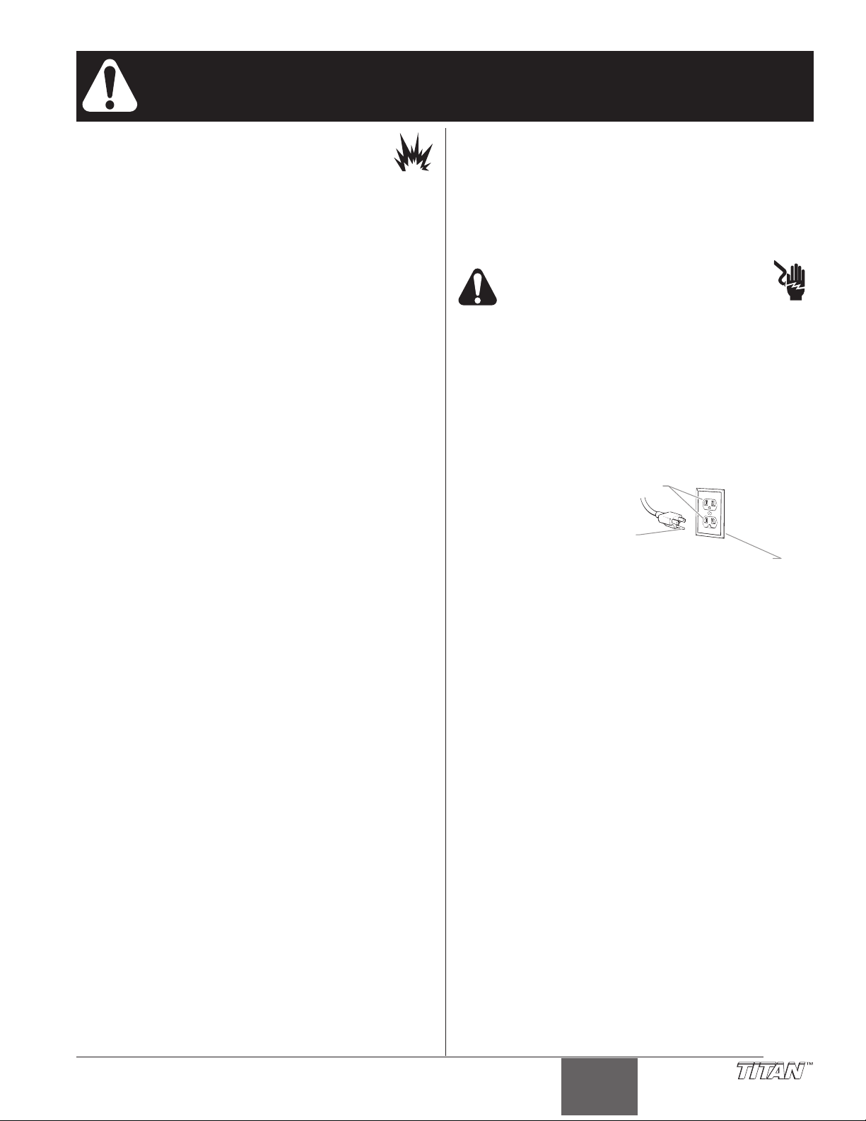
Grounded Outlet
Grounding Pin
Cover for grounded outlet box
Important Safety Information • Read all safety information before
operating the equipment. Save these instructions.
HAZARD: EXPLOSION HAZARD DUE TO
Will cause property damage or severe injury.
PREVENTION:
• Do not use materials containing bleach or chlorine.
• Do not use halogenated hydrocarbon solvents such as
• Contact your coating supplier about the compatibility of
HAZARD:
Can cause severe injury or property damage.
•
• Follow all appropriate local, state, and national codes
• The United States Government Safety Standards have
• Use only manufacturer authorized parts. User assumes
• All hoses, fittings, and filter parts must be secured before
• Before each use, check all hoses for cuts, leaks, abrasion
• Do not kink or over-bend the hose. Airless hose can
• Do not expose the hose to temperatures or pressures in
• Do not spray outdoors on windy days.
• Wear clothing to keep paint off skin and hair.
• Do not operate or spray near children. Keep children
• Do not overreach or stand on an unstable support. Keep
• Use lowest possible pressure to flush equipment.
• Stay alert and watch what you are doing.
• Do not operate the unit when fatigued or under the
• For electric units — Always unplug cord from outlet before
• Do not use the hose as a strength member to pull or lift
• Do not lift by cart handle when loading or unloading.
INCOMPATIBLE MATERIALS
bleach, mildewcide, methylene chloride and 1,1,1 trichloroethane. They are not compatible with aluminum.
material with aluminum.
GENERAL
Read all instructions and safety precautions before
operating equipment.
governing ventilation, fire prevention, and operation.
been adopted under the Occupational Safety and Health
Act (OSHA). These standards, particularly part 1910 of
the General Standards and part 1926 of the Construction
Standards should be consulted.
all risks and liabilities when using parts that do not meet
the minimum specifications and safety requirements of the
pump manufacturer.
operating spray pump. Unsecured parts can eject at great
force or leak a high pressure fluid stream causing severe
injury.
or bulging of cover. Check for damage or movement of
couplings. Immediately replace the hose if any of these
conditions exist. Never repair a paint hose. Replace it
with another grounded high-pressure hose.
develop leaks from wear, kinking and abuse. A leak can
inject material into the skin.
excess of those specified by manufacturer.
away from the equipment at all times.
effective footing and balance at all times.
influence of drugs or alcohol.
working on equipment.
the equipment.
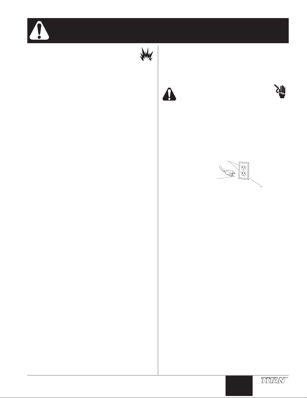
Grounding Instructions
This product must be grounded. In the event of an electrical
short circuit, grounding reduces the risk of electric shock by
providing an escape wire for the electric current. This product
is equipped with a cord having a grounding wire with an
appropriate grounding plug. The plug must be plugged into an
outlet that is properly installed and grounded in accordance
with all local codes and ordinances.
Improper installation of the grounding plug
can result in a risk of electric shock.
If repair or replacement of the cord or plug is necessary, do not
connect the green grounding wire to either flat blade terminal.
The wire with insulation having a green outer surface with or
without yellow stripes is the grounding wire and must be
connected to the grounding pin.
Check with a qualified electrician or serviceman if the
grounding instructions are not completely understood, or if you
are in doubt as to whether the product is properly grounded.
Do not modify the plug provided. If the plug will not fit the
outlet, have the proper outlet installed by a qualified
electrician.
IMPORTANT: Use only a 3-wire extension cord that has a
3-blade grounding plug and a 3-slot receptacle that will
accept the plug on the product. Make sure your extension
cord is in good condition. When using an extension cord,
be sure to use one heavy enough to carry the current your
product will draw. An undersized cord will cause a drop
in line voltage resulting in loss of power and overheating.
A 12 gauge cord is recommended. If an extension cord is
to be used outdoors, it must be marked with the suffix W-
after the cord type designation. For example, a
A
designation of SJTW-A would indicate that the cord would
be appropriate for outdoor use.
© Titan Tool Inc. All rights reserved. 3
English
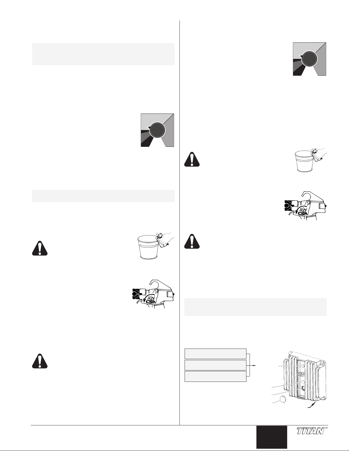
Page 4
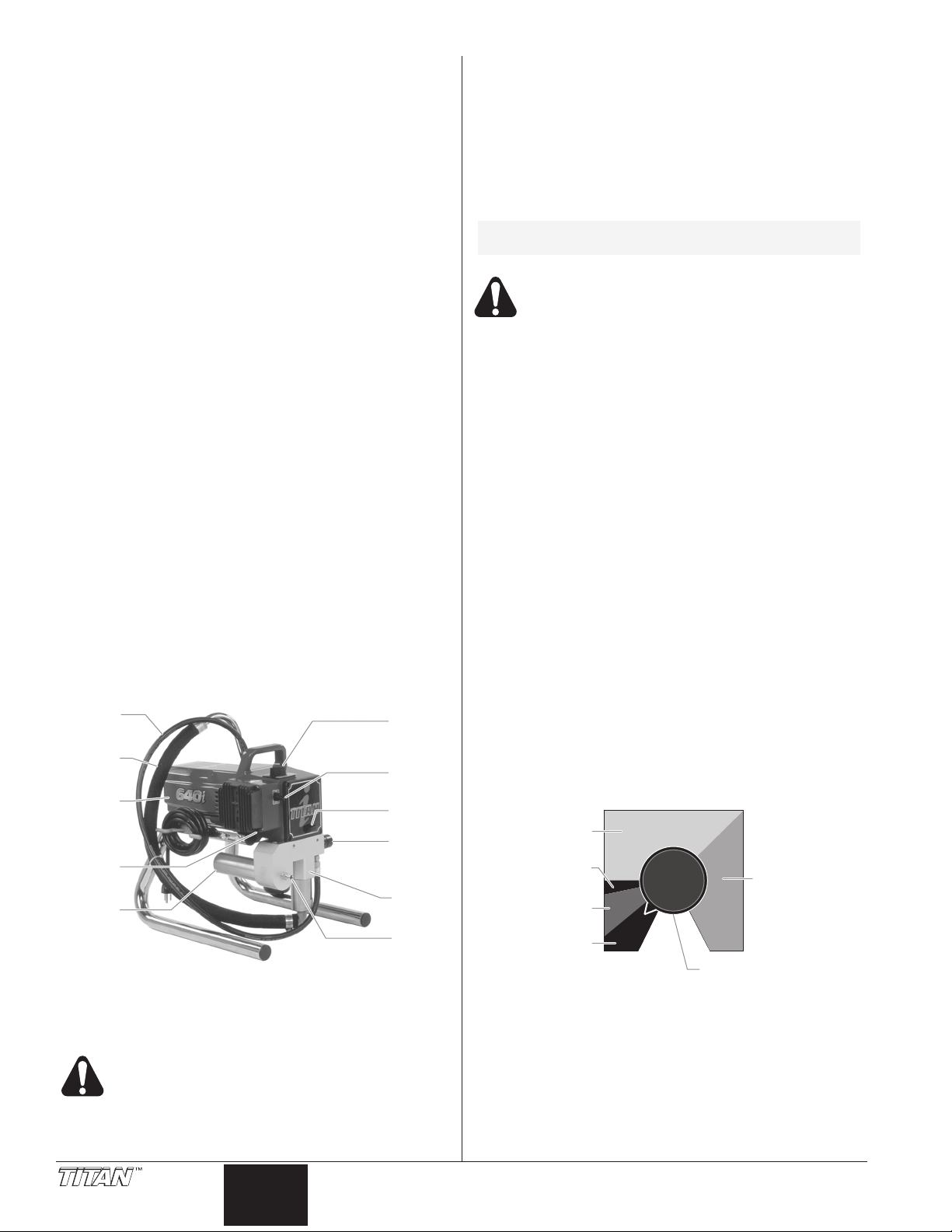
Table of Contents
Siphon
Hose
Motor
Circuit
Breaker
Filter
Return
Tube
ON/OFF
Switch
Oil Cup
Pressure
Control
Knob
PRIME/
SPRAY
Valve
Fluid
Section
Outlet
Fitting
Clean
Min.
PSI
Max.
PSI
Turbo PulseClean
(red zone)
OFF
(black zone)
Min. – 1800 PSI
(yellow zone)
OFF
(black zone)
1800 – 3200 PSI
(green zone)
Pressure Control Knob
Safety Precautions.................................................................2
General Description ...............................................................4
Operation ................................................................................4
Setup ....................................................................................4
Preparing to Paint.................................................................5
Painting.................................................................................5
Electronic Pressure Control Indicators .................................5
Pressure Relief Procedure ...................................................6
Spraying ..................................................................................6
Spraying Technique ..............................................................6
Practice.................................................................................7
Cleanup ...................................................................................7
Maintenance............................................................................8
General Repair and Service Notes.......................................8
Replacing the Motor .............................................................8
Replacing the Motor Brushes ...............................................8
Replacing the Gears.............................................................8
Replacing the Transducer.....................................................9
Replacing the PRIME/SPRAY Valve.....................................9
Servicing the Fluid Section.................................................10
Replacing the Filters ...........................................................11
Troubleshooting ...................................................................12
Warranty................................................................................13
Parts Listings........................................................................38
Main Assembly....................................................................38
Motor Assembly ..................................................................39
Gear Box Assembly............................................................40
Fluid Section Assembly ......................................................42
Suction Set Assembly.........................................................44
Stand Assembly..................................................................44
Low Rider Assembly...........................................................45
High Rider Assembly ..........................................................46
Siphon Tube Assembly (High Rider Assembly) ..................46
Accessories ........................................................................47
Electrical Schematic ...........................................................49
Setup
Perform the following procedure before plugging in the power
cord of an electric unit.
1. Ensure that the suction set/siphon tube and the return
hose are attached and secure.
2. Using a wrench, attach a minimum of 50’ of 1/4” nylon
airless spray hose to the unit. Tighten securely.
3. Attach an airless spray gun to the spray hose. Using two
wrenches (one on the gun and one on the hose), tighten
securely.
NOTE: Do not attach the tip to the spray gun yet.
4. Make sure the pressure control knob is in its OFF position
5.
6. Fill the oil cup with one tablespoon of piston seal lubricant
IMPORTANT: Never operate unit for more than ten
seconds without fluid. Operating this unit without fluid
will cause unnecessary wear to the packings.
7. Make sure the electrical service is 120V, 15 amp minimum.
8.
IMPORTANT: Always use a minimum 12 gauge, three-wire
extension cord with a grounded plug. Never remove the
third prong or use an adapter.
Remove the tip if it is already attached.
Make sure all airless hoses and spray guns are
electrically grounded and rated for at least 3200
psi (21.1 MPa) fluid pressure.
in the black zone.
Make sure the ON/OFF switch is in its OFF position.
(Piston Lube).
Plug the power cord into a properly grounded outlet at
least 25’ from the spray area.
General Description
This airless sprayer is a precision power tool used for spraying
many types of materials. Read and follow this instruction
manual carefully for proper operating instructions,
maintenance, and safety information.
Operation
This equipment produces a fluid stream at
extremely high pressure. Read and understand
the warnings in the Safety Precautions section at
the front of this manual before operating this
equipment.
English
Preparing a New Sprayer
If this unit is new, it is shipped with test fluid in the fluid section
to prevent corrosion during shipment and storage. This fluid
must be thoroughly cleaned out of the system with mineral
spirits before you begin spraying.
IMPORTANT: Always keep the trigger lock on the spray
gun in the locked position while preparing the system.
1. Place the suction tube into a container of mineral spirits
that has a flash point of 140ºF (60ºC) or above.
Place the return hose into a metal waste container.
2.
3. Set the pressure to minimum by turning the pressure
control knob to the “Min” setting in the yellow zone.
4. Move the PRIME/SPRAY valve down to the PRIME
position.
5. Turn the unit on by moving the ON/OFF switch to the ON
position.
6. Allow the sprayer to run for 15–30 seconds to flush the
test fluid out through the return hose and into the waste
container.
7. Turn the unit off by moving the ON/OFF switch to the OFF
position.
4 © Titan Tool Inc. All rights reserved.
Page 5
Preparing to Paint
Trigger lock
in locked position.
Max.
PSI
Clean
Min.
PSI
Pressure
Indicator
Motor Running Indicator
Programmer Port
Programmer Port
Dust Cover
Circuit
Breaker
Blinking Yellow =
0 PSI – priming pressure
Solid Yellow =
priming pressure – 1800 PSI
Solid Green =
1800 PSI – 3200 PSI
Trigger lock
in locked position.
Max.
PSI
Clean
Min.
PSI
Before painting, it is important to make sure that the fluid in the
system is compatible with the paint that is going to be used.
NOTE: Incompatible fluids and paint may cause the
IMPORTANT: Always keep the trigger lock on the spray
gun in the locked position while preparing the system.
1. Place the suction tube into a container of the appropriate
2. Place the return hose into a metal waste container.
3. Set the pressure to minimum by turning
4. Move the PRIME/SPRAY valve down to
5. Turn the unit on by moving the ON/OFF
6. Allow the sprayer to run for 15–30 seconds to flush the old
7. Turn the unit off by moving the ON/OFF switch to the OFF
NOTE: Make sure that the spray gun does not have a
8. Move the PRIME/SPRAY valve up to the SPRAY position.
9. Turn the unit on.
10.Unlock the gun by turning the gun trigger lock to the
11.Trigger the gun into the metal waste container until the old
12.
13. Set down the gun and increase the
14. Check the entire system for leaks. If
15. Follow the “Pressure Relief Procedure” in this manual
valves to become stuck closed, which would
require disassembly and cleaning of the
sprayer’s fluid section.
solvent for the material being sprayed (refer to
recommendations of the material manufacturer).
An
example of the appropriate solvent is water for latex paint.
the pressure control knob to the “Min”
setting in the yellow zone.
the PRIME position.
switch to the ON position.
solvent out through the return hose and into the metal
waste container.
position.
tip or tip guard installed.
unlocked position.
Ground the gun by holding it
against the edge of the metal
container while flushing. Failure
to do so may lead to a static
electric discharge, which may
cause a fire.
solvent is gone and fresh solvent is coming out of the gun.
Lock the gun by turning the gun trigger
lock to the locked position.
pressure by turning the pressure
control knob slowly clockwise into the
green zone.
leaks occur, follow the “Pressure Relief Procedure” in this
manual before tightening any fittings or hoses.
before changing from solvent to paint.
Be sure to follow the pressure relief procedure
when shutting down the sprayer for any purpose,
including servicing or adjusting any part of the
spray system, changing or cleaning spray tips, or
preparing for cleanup.
Painting
1. Place the suction tube into a container of paint.
2. Place the return hose into a metal waste container.
3. Set the pressure to minimum by turning
the pressure control knob to the “Min”
setting in the yellow zone.
4. Move the PRIME/SPRAY valve down to
the PRIME position.
5. Turn the unit on by moving the ON/OFF
switch to the ON position.
6. Allow the sprayer to run until paint is coming through the
return hose into the metal waste container.
7. Turn the unit off by moving the ON/OFF switch to the OFF
position.
8. Remove the return hose from the waste container and
place it in its operating position above the container of
paint.
9. Move the PRIME/SPRAY valve up to the SPRAY position.
10. Turn the unit on.
11. Unlock the gun by turning the gun trigger lock to the
unlocked position.
Ground the gun by holding it against
the edge of the metal container while
flushing. Failure to do so may lead
to a static electric discharge, which
may cause a fire.
12. Trigger the gun into the metal waste container until all air
and solvent is flushed from the spray hose and paint is
flowing freely
. from the gun.
13. Lock the gun by turning the gun
trigger lock to the locked position.
14. Turn the unit off.
15. Attach tip guard and tip to the gun as
instructed by the tip guard or tip
manuals.
POSSIBLE INJECTION
HAZARD. Do not spray
without the tip guard in place. Never trigger the
gun unless the tip is in either the spray or the
unclog position. Always engage the gun trigger
lock before removing, replacing or cleaning tip.
16. Turn the unit on.
1
7. Increase the pressure by turning the pressure control knob
slowly clockwise toward the green zone and test the spray
pattern on a piece of cardboard. Adjust the pressure
control knob until the spray from the gun is completely
atomized. Try to keep the pressure control knob at the
lowest setting that maintains good atomization.
NOTE: Turning the pressure up higher then needed to
atomize the paint will cause premature tip wear
and additional overspray.
Electronic Pressure Control Indicators
The following is a description of the indicators on the electronic
pressure control.
© Titan Tool Inc. All rights reserved. 5
English
Page 6
Pressure Indicator
Trigger lock
in locked position.
Too Thick
Offspray
Arcing Gun at angle
start
stroke
release
trigger
pull
trigger
end
stroke
The pressure indicator shows the current operating pressure of
the sprayer. It has three different indications: blinking yellow,
solid yellow, and solid green.
Blinking Yellow
When the pressure indicator is blinking yellow, the sprayer is
operating between 0 and 200 PSI.
indicator means:
• The sprayer is plugged in and turned “ON”
• The sprayer is at priming pressure (little or no pressure)
• It is safe to move the PRIME/SPRAY valve between
positions
• It is safe to change or replace the spray tip (refer to gun
manual for tip replacement instructions).
NOTE: If the pressure indicator begins blinking yellow
when the pressure control knob is set at a
higher pressure and the PRIME/SPRAY valve is
in the SPRAY position, either the spray tip is
worn, there is a leak, or the sprayer is in need
of service/repair.
Solid Yellow
When the pressure indicator is solid yellow, the sprayer is
operating between 200 and 1800 PSI.
indicator means:
• The sprayer is at the proper pressure setting for spraying
stain, lacquer, varnish, and multi-colors
• If the pressure indicator goes to solid yellow when the
pressure is set so that it starts at solid green, it indicates
one of the following:
a. Tip Wear Indicator — when spraying with latex or at
high pressure the solid yellow appears. This means
the tip is worn and needs to be replaced.
b. Tip Too Large — when a tip that is too large for the
sprayer is put in the gun, the pressure indicator will turn
from solid green to solid yellow.
c. Fluid Section Wear — if a solid yellow pressure
indicator appears when using a new tip and the
pressure is set at maximum, service may be required
(worn packings, worn piston, stuck valve, etc...).
Solid Green
When the pressure indicator is solid green, the sprayer is
operating between 1800 and 3200 PSI. A
indicator means:
• The sprayer is at the proper pressure setting for spraying
oil-based and latex house paints
• The sprayer is operating at peak performance at a high
pressure setting
A blinking yellow pressure
A solid yellow pressure
solid green pressure
Motor Running Indicator
The Motor Running indicator is on when the motor is
commanded to run. This indicator is used by service centers
to troubleshoot motor problems.
5. Hold the metal part of the gun firmly to
the side of a metal container to ground
the gun and avoid a build up of static
electricity.
6. Trigger the gun to remove any
pressure that may still be in the hose.
7. Lock the gun by turning the gun trigger lock to the locked
position.
8. Move the PRIME/SPRAY valve down to the PRIME
position.
Spraying
POSSIBLE INJECTION HAZARD. Do not spray
without the tip guard in place. Never trigger the
gun unless the tip is in either the spray or the
unclog position. Always engage the gun trigger
lock before removing, replacing, or cleaning tip.
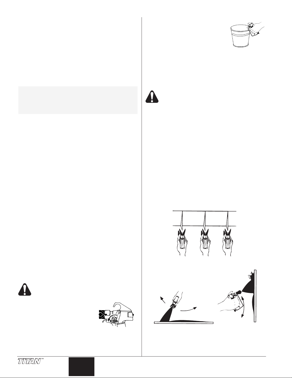
Spraying Technique
The following techniques, if followed, will assure professional
painting results.
Hold the gun perpendicular to the surface and always at equal
distance from the surface. Depending on the type of material,
surface, or desired spray pattern, the gun should be held at a
distance of 12 to 14 inches (30 to 35 cm).
Move the gun either across or up and down the surface at a
steady rate. Moving the gun at a consistent speed conserves
material and provides even coverage. The correct spraying speed
allows a full, wet coat of paint to be applied without runs or sags.
Holding the gun closer to the surface deposits more paint on
the surface and produces a narrower spray pattern. Holding
the gun farther from the surface produces a thinner coat and
wider spray pattern. If runs, sags, or excessive paint occur,
change to a spray tip with a smaller orifice. If there is an
insufficient amount of paint on the surface or you desire to
spray faster, a larger orifice tip should be selected.
Maintain uniform spray stroke action. Spray alternately from
left to right and right to left. Begin movement of the gun before
the trigger is pulled.
Avoid arcing or holding the gun at an angle. This will result in
an uneven finish.
Pressure Relief Procedure
1. Lock the gun by turning the gun
trigger lock to the locked position.
2. T
ON/OFF switch to the OFF position.
3. Turn the pressure control knob
counterclockwise to its OFF position
in the black zone.
4. Unlock the gun by turning the gun
trigger lock to the unlocked position.
Be sure to follow the pressure relief procedure
when shutting the unit down for any purpose,
including servicing or adjusting any part of the
spray system, changing or cleaning spray tips, or
preparing for cleanup.
urn the unit off by moving the
English
Proper lapping (overlap of spray pattern) is essential to an
even finish. Lap each stroke. If you are spraying horizontally,
aim at the bottom edge of the preceding stroke, so as to lap
the previous pattern by 50%.
6 © Titan Tool Inc. All rights reserved.
Page 7
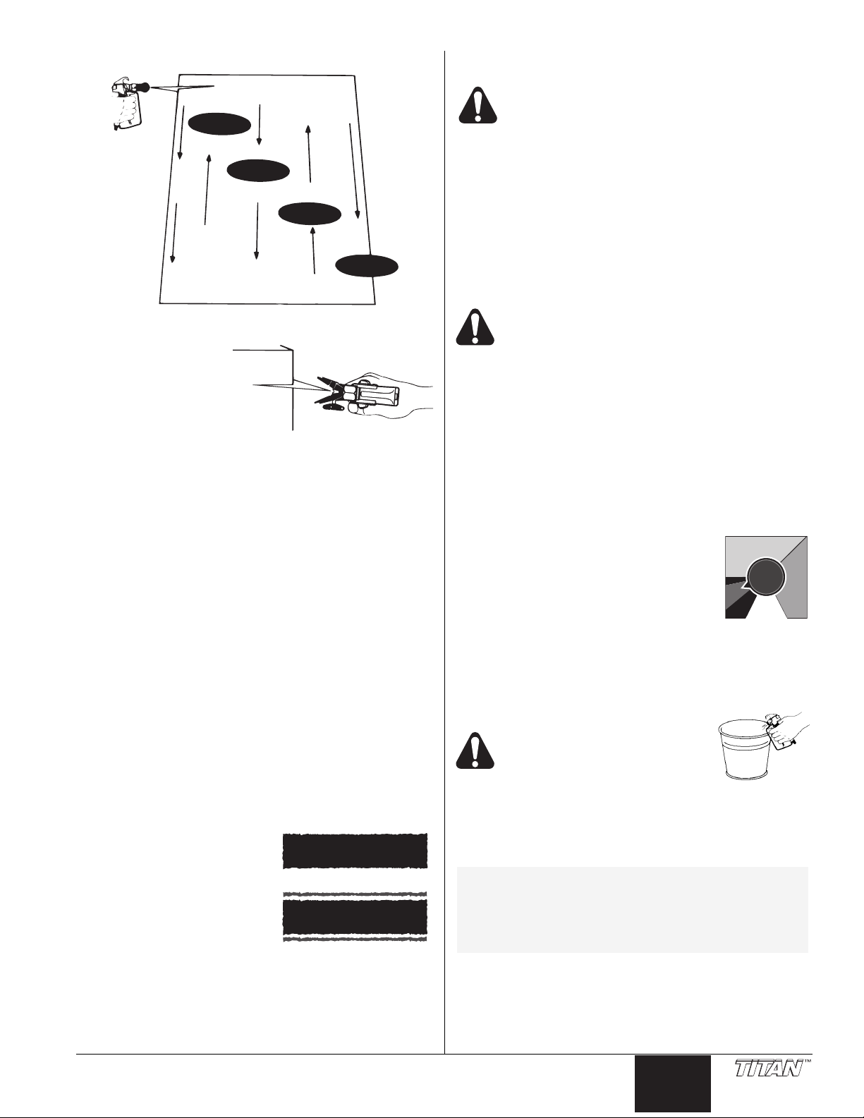
For corners and edges,
Good spray pattern
Paint tailing pattern
Overlap edges
1st
pass
2nd
pass
3rd
pass
4th
pass
5th
pass
Min.
PSI
Max.
PSI
Clean
split the center of the
spray pattern on the
corner or edge and spray
vertically so that both
adjoining sections receive
approximately even
amounts of paint.
When spraying with a shield, hold it firmly against the surface.
Angle the spray gun slightly away from the shield and toward
the surface. This will prevent paint from being forced
underneath.
Shrubs next to houses should be tied back and covered with a
canvas cloth. The cloth should be removed as soon as
possible. Titan gun extensions are extremely helpful in these
situations.
Nearby objects such as automobiles, outdoor furniture, etc.
should be moved or covered whenever in the vicinity of a
spray job. Be careful of any other surrounding objects that
could be damaged by overspray.
Practice
1. Be sure that the paint hose is free of kinks and clear of
objects with sharp cutting edges.
2. Turn the pressure control knob counterclockwise to its to
its lowest setting.
3. Turn the PRIME/SPRAY valve up to its SPRAY position.
4. Turn the pressure control knob clockwise to its highest
setting. The paint hose should stiffen as paint begins to
flow through it.
5. Unlock the gun trigger lock.
6. Trigger the spray gun to bleed air out of the hose.
7. When paint reaches the spray tip, spray a test area to
check the spray pattern.
8. Use the lowest pressure
setting necessary to get a
good spray pattern. If the
pressure is set too high, the
spray pattern will be too light.
If the pressure is set too low,
tailing will appear or the paint
will spatter out in gobs rather
than in a fine spray.
Cleanup
Special cleanup instructions for use with
flammable solvents:
• Always flush spray gun preferably outside and at least one
hose length from spray pump.
• If collecting flushed solvents in a one gallon metal
container, place it into an empty five gallon container, then
flush solvents.
• Area must be free of flammable vapors.
• Follow all cleanup instructions.
IMPORTANT: The sprayer, hose, and gun should be
cleaned thoroughly after daily use. Failure to do so
permits material to build up, seriously affecting the
performance of the unit.
Always spray at minimum pressure with the gun
nozzle tip removed when using mineral spirits or
any other solvent to clean the sprayer, hose, or
gun. Static electricity buildup may result in a fire
or explosion in the presence of flammable vapors.
1. Follow the “Pressure Relief Procedure” found in the
Operation section of this manual.
Remove the gun tip and tip guard and clean with a brush
2.
using the appropriate solvent.
3. Place the suction tube into a container of the appropriate
solvent (refer to recommendations of the material
manufacturer). An example of the appropriate solvent is
water for latex paint.
4. Place the return hose into a metal waste container.
5. Move the PRIME/SPRAY valve down to its PRIME
position.
6. Set the pressure to Turbo PulseClean by
turning the pressure control knob to its
CLEAN position in the red zone.
7. Turn the unit on by moving the ON/OFF
switch to the ON position.
8. Allow the solvent to circulate through the
unit and flush the paint out of the return
hose into the metal waste container.
9. Turn the unit off by moving the ON/OFF switch to the OFF
position.
10. Move the PRIME/SPRAY valve up to its SPRAY position.
11. Turn the unit on.
Ground the gun by holding it
against the edge of the metal
container while flushing. Failure
to do so may lead to a static
electric discharge, which may
cause a fire.
12. Trigger the gun into the metal waste container until the
paint is flushed out of the hose and solvent is coming out
of the gun.
13.
Continue to trigger the spray gun into the waste container
until the solvent coming out of the gun is clean.
NOTE: For long-term or cold weather storage, pump
14. Follow the “Pressure Relief Procedure” found in the
15. Unplug the unit and store in a clean, dry area.
IMPORTANT: Do not store the unit under pressure.
mineral sprits through the entire system.
For short-term storage when using latex paint,
pump water mixed with Titan Liquid Shield
through the entire system (see the Accessories
section of this manual for part number).
Operation section of this manual.
© Titan Tool Inc. All rights reserved. 7
English
Page 8
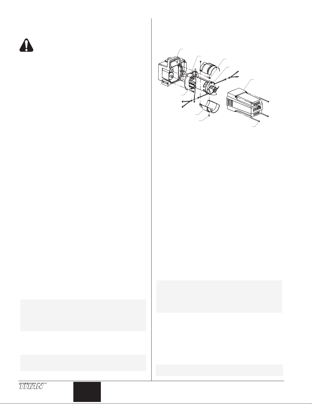
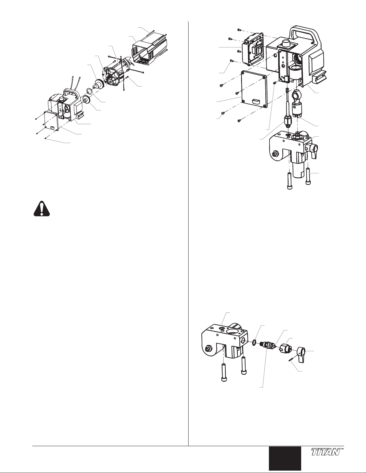
Motor Cover
Brush Cover
Motor
Motor Mounting Screw
Pump Housing
Capacitors
Shroud
Shroud Screw
Motor Cover Screw
BLACK
BLACKBLACK
REDRED
BLACK
RED
RED
Maintenance
Before proceeding, follow the Pressure Relief
Procedure outlined previously in this manual.
Additionally, follow all other warnings to reduce
the risk of an injection injury, injury from moving
parts or electric shock. Always unplug the
sprayer before servicing!
General Repair and Service Notes
The following tools are needed when repairing this sprayer:
Phillips Screwdriver 3/8" Hex Wrench
Needle Nose Pliers 5/16" Hex Wrench
Adjustable Wrench 1/4" Hex Wrench
Rubber Mallet 3/16" Hex Wrench
Flat-blade Screwdriver 5/32” Hex Wrench
1. Before repairing any part of the sprayer, read the
instructions carefully, including all warnings.
IMPORTANT: Never pull on a wire to disconnect it. Pulling
on a wire could loosen the connector from the wire.
2. Test your repair before regular operation of the sprayer to
be sure that the problem is corrected. If the sprayer does
not operate properly
determine if everything was done correctly. Refer to the
Troubleshooting Charts to help identify other possible
problems.
3. Make certain that the service area is well ventilated in
case solvents are used during cleaning. Always wear
protective eyewear while servicing. Additional protective
equipment may be required depending on the type of
cleaning solvent. Always contact the supplier of solvents
for recommendations.
4. If you have any further questions concerning your TITAN
Airless Sprayer, call TITAN:
Customer Service (U.S.) .......................1-800-526-5362
Fax ................................................1-800-528-4826
Customer Service (Canada)..................1-800-565-8665
Fax ................................................ 1-905-856-8496
Customer Service (International)...........1-201-337-1240
Fax ................................................1-201-405-7449
Replacing the Motor
1. Unplug the unit.
2. Loosen and remove the four motor cover screws.
Remove the motor cover.
3. Disconnect the black and red wires coming from the pump
housing. Disconnect the black and red wires from the
capacitors. Disconnect the black and red wires from the
motor.
4. Remove the capacitors from their mounting clip.
5. Loosen and remove the four motor mounting screws.
6. Pull the motor out of the pump housing.
NOTE: If the motor will not dislodge from the pump
7. With the motor removed, inspect the gears in the pump
8. Install the new motor into the pump housing.
NOTE: Rotate the motor fan manually until the
9. Secure the motor with the four motor mounting screws.
housing:
• Remove the front cover plate.
• Using a rubber mallet, carefully tap on the
front of the motor crankshaft that extends
through the connecting rod.
housing for damage or excessive wear. Replace the
gears, if necessary.
armature gear engages with the mating gear in
the pump housing.
, review the repair procedure to
English
10. Push the capacitors into their clip on the new motor.
11. Reconnect the wires (refer to the electrical schematic in
the Parts List section of this manual).
12. Slide the motor cover over the motor. Secure the motor
cover with the four motor cover screws.
Replacing the Motor Brushes
Perform this procedure using Motor Brush Kit P/N 704-276.
1. Loosen and remove the four motor cover screws.
Remove the motor cover.
2. Loosen and remove the two shroud screws. Remove the
shroud.
3. Using a small screwdriver, pry off the two plastic brush
covers.
4. Disconnect the black and red wires from the motor
brushes. Remove the motor brushes.
5. Install the new motor brushes and snap on the plastic
brush covers.
6. Reconnect the black and red wires from the motor
brushes (refer to the electrical schematic in the Parts List
section of this manual).
7. Position the shroud over the motor fan. Secure the
shroud with the two shroud screws.
8. Slide the motor cover over the motor. Secure the motor
cover with the four motor cover screws.
Replacing the Gears
1. Loosen and remove the four motor cover screws.
Remove the motor cover.
2. Disconnect the black and red wires coming from the pump
housing.
3. Loosen and remove the four motor mounting screws.
4. Pull the motor out of the pump housing.
NOTE: If the motor will not dislodge from the pump
housing:
• Remove the front cover plate.
• Using a rubber mallet, carefully tap on the
front of the motor crankshaft that extends
through the connecting rod.
5. Inspect the armature gear on the end of the motor for
damage or excessive wear. If this gear is completely
worn out, replace the entire motor.
6. Remove and inspect the 2nd stage gear for damage or
excessive wear. Replace if necessary.
7. Remove and inspect the gear and crank assembly for
damage or excessive wear. Replace if necessary.
8. Reassemble the pump by reversing the above steps.
During reassembly, make sure the thrust washers is in
place.
NOTE: Refill the gear box with five ounces of
Lubriplate (P/N 314-171).
8 © Titan Tool Inc. All rights reserved.
Page 9
RED
BLACK
Front Cover
Pump Housing
Front Cover Screw
2nd Stage Gear
Thrust Washer
Motor Mounting
Screw
Gear and Crank
Assembly
Armature Gear
Motor
Motor Cover
Motor Cover Screw
Gasket
Cam Base
Valve Stem
Pump Block
Valve Housing
Assembly
Valve
Handle
Groove Pin
T-Slot
Pump
Housing
Pump
Block
Pump
Block
Mounting
Screw
Front
Cover
EPC
Mounting
Screw
Electronic
Pressure
Control
(EPC)
Front
Cover
Screw
Set Screw
Transducer
Assembly
Replacing the Transducer
1. Loosen and remove the four front cover screws. Remove
the front cover.
2. Stop the sprayer at the bottom of its stroke so that the
piston is in its lowest position. Turn off and unplug the
sprayer.
Before proceeding, follow the Pressure Relief
Procedure outlined previously in this manual.
Additionally
the risk of an injection injury, injury from moving
parts or electric shock. Always unplug the
sprayer before servicing!
3. Tilt the pump back for easy access to the fluid section.
4. Using a 3/8” hex wrench, loosen and remove the two
pump block mounting screws.
5. Pull the pump block down approximately 1/2” from the
pump housing to clear the transducer.
6. Slide the pump block and piston rod forward until the
piston rod is out of the T-slot on the connecting rod.
7. Loosen and remove the four electronic pressure control
(EPC) mounting screws.
8. Pull back the EPC for access to the transducer plug-in.
9. Unplug the transducer connection from EPC board
location “JP3” (refer to the electrical schematic in the
Parts List section of this manual).
10. Using an 1/8” hex wrench, loosen and remove the set
screw from the bottom of the pump housing.
11. Slide the transducer assembly out of the bottom of the
pump housing.
12. Install the new transducer assembly into the pump
housing.
13. Thread the set screw into the pump housing and tighten
securely.
14. Plug the transducer connection into the EPC board at
15. Reassemble the pump by reversing steps 1–8.
IMPORTANT: Make sure the transducer is aligned
properly with the hole in the pump block during
reassembly. Improper alignment may cause damage to
the transducer gasket.
location “JP3” (refer to the electrical schematic in the
Parts List section of this manual).
, follow all other warnings to reduce
Replacing the PRIME/SPRAY Valve
Perform the following procedure using PRIME/SPRAY valve
replacement kit P/N 700-258.
1. Push the groove pin out of the valve handle.
2. Remove the valve handle and the cam base.
3. Using a wrench, loosen and remove the valve housing
assembly.
4. Make sure the gasket is in place and thread the new valve
housing assembly into the pump block. Tighten securely
with wrench.
5. Place the cam base over the valve housing assembly.
Lubricate the cam base with grease and line up the cam
with the pump block.
6. Line up the hole on the valve stem with the hole in the
valve handle.
7. Insert the groove pin into the valve handle and through
the valve stem to secure the valve handle in position.
© Titan Tool Inc. All rights reserved. 9
English
Page 10
Servicing the Fluid Section
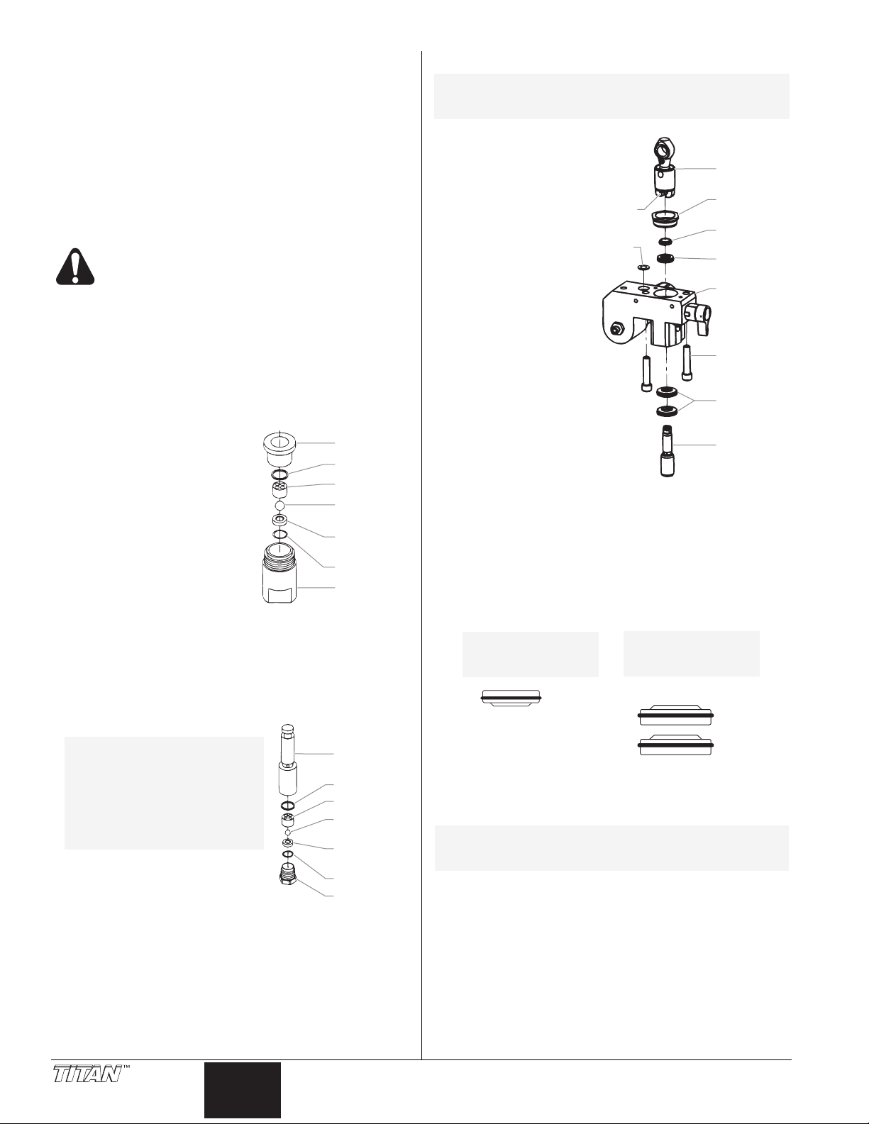
Outlet Valve
Housing
Outlet Valve
Seat
Outlet Valve
Ball
Upper Cage
Upper Seal
Piston Rod
O-Ring
Foot Valve
Housing
Foot Valve
Seat
Foot Valve
Ball
Bushing
O-Ring
Lower Cage
Lower Seal
Install lower packings
with raised lip and O-ring
facing up.
Install upper packing
with raised lip and O-ring
facing down.
O-Ring
O-Ring
Raised Lip
Raised Lip
Connecting
Rod
Retainer
Nut
Piston
Guide
Upper
Packing
Pump
Block
Lower
Packings
Pump Block
Mounting
Screw
Piston Rod
T-Slot
Transducer
Gasket
Use the following procedures to service the valves and repack
the fluid section. Perform the following steps before
performing any maintenance on the fluid section.
1. Loosen and remove the four front cover screws. Remove
the front cover.
2. Stop the sprayer at the bottom of its stroke so that the
piston is in its lowest position. Turn off and unplug the
sprayer.
Before proceeding, follow the Pressure Relief
Procedure outlined previously in this manual.
Additionally
the risk of an injection injury, injury from moving
parts or electric shock. Always unplug the
sprayer before servicing!
3. Unscrew the return hose assembly from the pump block.
Remove the retaining clip that holds the suction set in the
4.
foot valve. Pull the suction set out of the foot valve.
5. Tilt the pump back for easy access to the fluid section.
Servicing the Valves
The design of Titan's fluid section
allows access to the foot valve and
seat as well as the outlet valve and
seat without completely
disassembling the fluid section. It
is possible that the valves may not
seat properly because of debris
stuck in the foot valve seat or outlet
valve seat. Use the following
instructions to clean the valves and
reverse or replace the seats.
1. Using a wrench, loosen and
remove the foot valve housing from the pump block.
2. Clean out any debris in the foot valve housing and
examine the valve housing and seat. If the seat is
damaged, reverse or replace the seat.
3. Using a 3/8" hex wrench, loosen and remove the outlet
valve housing from the piston rod.
, follow all other warnings to reduce
Repacking the Fluid Section
NOTE: The factory-installed packings are black in
color. The replacement packings in the
packing replacement kit are white.
1. Remove the foot
valve and outlet
valve assemblies
using the steps in
the “Servicing the
Valves” procedure
above.
2. Using 3/8” a hex
wrench, loosen
and remove the
two pump block
mounting screws.
3. Pull the pump
block down
approximately 1/2”
from the pump
housing.
4. Slide the pump
block and piston
rod forward until
the piston rod is
out of the T-slot
on the connecting
rod.
5. Slide the piston rod out through the bottom of the pump
block
6. Loosen and remove the retainer nut and piston guide from
the pump block.
7. Remove the upper and lower packings from the pump
block.
8. Clean the pump block and install the new upper and lower
packings. Refer to the illustration below for proper
packing orientation.
NOTE: Always service the
4. Clean out any debris and
examine the valve housing and
seat. If the seat is damaged,
reverse or replace the seat.
5. Remove, clean, and inspect the upper cage and upper
ball. Replace if they are worn or damaged.
6. Reassemble the valves by reversing the steps above.
outlet valve with the
piston rod attached to
the pump. This will
prevent the piston rod
from rotating during
disassembly of the
outlet valve.
English
9. Inspect the piston rod for wear and replace if necessary.
10. Reassemble the outlet valve assembly into the piston rod.
Tighten the outlet valve housing with a wrench until
secure.
NOTE: Use the T-slot on the connecting rod to hold
the piston rod in position while securing the
outlet valve housing.
IMPORTANT: Never use a wrench on the piston itself.
This could cause damage to the piston and cause leakage.
11. Insert the piston guide into the retainer nut.
Thread the
retainer nut into the pump block until it is hand tight.
12. Slide the piston guide tool (included in the repacking kit)
over the top of the piston rod and insert the piston rod
through the bottom of the pump block. Using a rubber
mallet, tap the bottom of the piston rod lightly until the
piston rod is in position in the pump block.
10 © Titan Tool Inc. All rights reserved.
Page 11
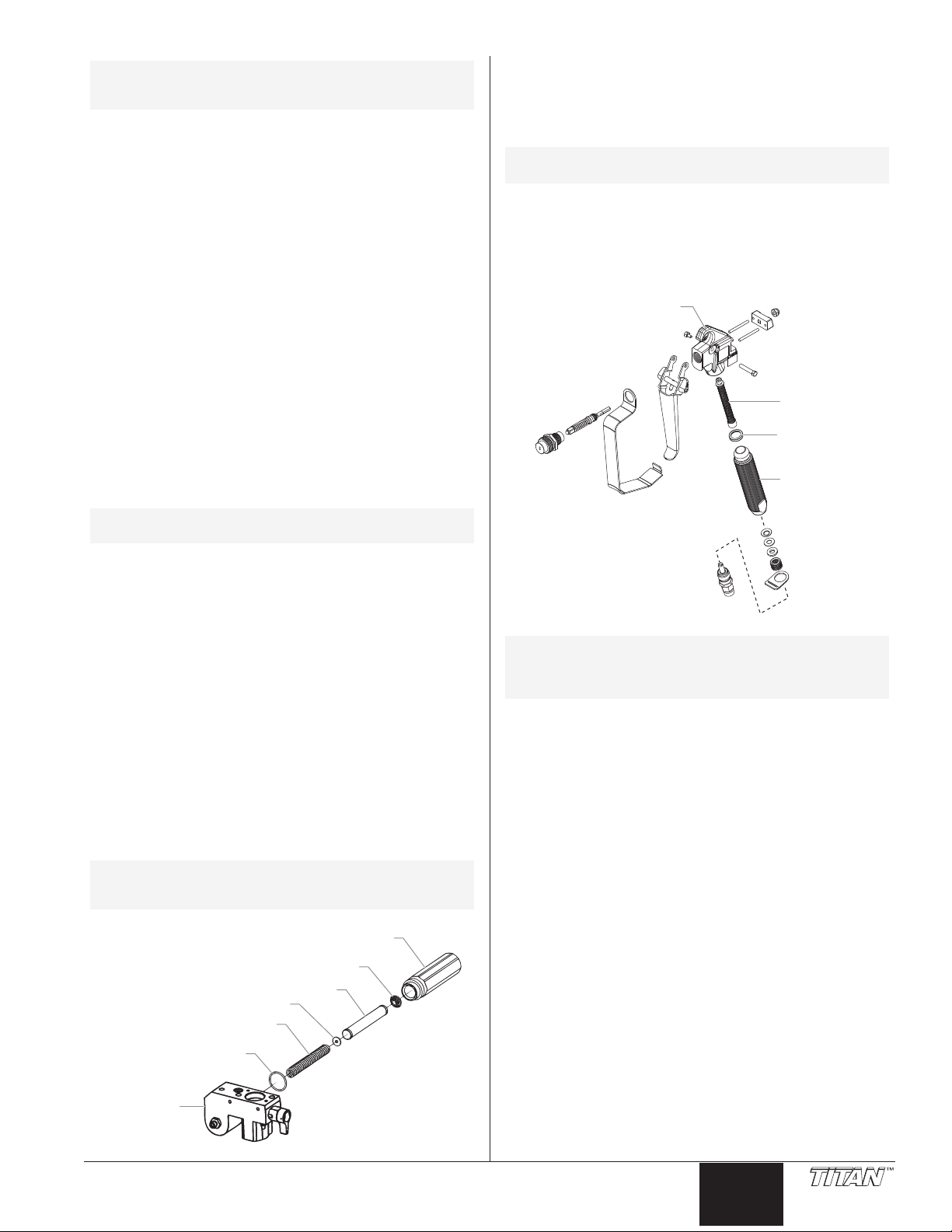
Pump Block
O-Ring
Filter
Adapter
Filter Support Spring
Filter Spring
Filter Housing
NOTE: Coat the piston guide tool and the piston rod
Gun Head
Handle Seal
Filter
Handle
13. Using a wrench, tighten the retainer nut securely.
14. Slide the top of the piston rod into the T-slot on the
15. Position the pump block underneath the pump housing
IMPORT
properly with the hole in the pump block during
reassembly. Improper alignment may cause damage to
the transducer gasket.
16. Thread the pump block mounting screws through the
17. Reassemble the foot valve assembly into the pump block.
18. Insert the elbow on the suction set into the bottom of the
19. Thread the return hose into the pump block and tighten
20. Place the front cover on the pump housing and secure in
21. Turn on the sprayer by following the procedure in the
NOTE: Repacking kit P/N 730-401 is available. For
with grease before inserting them into the
pump block.
connecting rod.
and push up until it rests against the pump housing.
ANT: Make sure the transducer is aligned
pump block and into the pump housing.
foot valve. Position the retaining clip into the foot valve to
secure the suction set assembly.
securely.
position using the four front cover screws.
“Operation” section of this manual and check for leaks.
best results use all parts supplied in this kit.
Tighten securely.
Gun Filter
1. Move the gun trigger lock to the unlocked position.
2. Loosen and remove the handle from the gun head.
3. Turning clockwise, unscrew the filter from the gun head.
NOTE: Left-handed threads require turning the filter
clockwise to remove.
4. Turning counterclockwise, screw the new or cleaned filter
into the gun head.
5. Make sure the handle seal is in position and thread the
handle into the gun head until secure.
6. Move the gun trigger lock to the locked position.
Replacing the Filters
Pump Filter
1. Loosen and remove the filter housing by hand.
2. Slip the filter off of the filter support spring.
3. Inspect the filter. Based on inspection, clean or replace
the filter.
4. Inspect the o-ring. Based on inspection, clean or replace
the o-ring.
5. Slide the new or cleaned filter over the filter support spring
with the adapter in place. Push the filter into the center of
the pump block.
6. Slide the filter housing over the filter and thread it into the
pump block until secure.
NOTE: The filter housing should be hand-tightened,
but make sure the filter housing is seated fully
into the pump block.
NOTE: For more detail, part number information, and
assembly drawings at larger scale, please see
the LX -80 II Professional Airless Gun Owner's
Manual (P/N 313-2069).
© Titan Tool Inc. All rights reserved. 11
English
Page 12

Problem
The unit will not run.
Troubleshooting
Cause
1. The unit is not plugged in.
2. Tripped breaker.
3. The pressure is set too low (pressure
control knob set at minimum setting
does not supply power to unit).
4. Faulty or loose wiring.
5. Excessive motor temperature.
6. ON/OFF switch is defective.
Solution
1. Plug the unit in.
2. Reset the breaker.
3. Turn the pressure control knob clockwise to
supply power to the unit and increase the
pressure setting.
4. Inspect or take to a Titan authorized service
center.
5. Allow motor to cool.
6. Replace the ON/OFF switch.
The unit will not prime.
The unit will not build or
maintain pressure.
1. The PRIME/SPRAY valve is in the
SPRAY position.
2. Air leak in the siphon tube/suction set.
3. The pump filter and/or inlet screen is
clogged.
4. The siphon tube/suction set is clogged.
1. The spray tip is worn.
2. The spray tip is too large.
3. The pressure control knob is not set
properly.
4. The pump filter, gun filter, or inlet
screen is clogged.
5. Material flows from the return hose
when the PRIME/SPRAY valve is in the
SPRAY position.
6. Air leak in the siphon tube/suction set.
7. There is external fluid leak.
8. There is an internal fluid section leak
(packings are worn and/or dirty, valve
balls are worn).
9. Worn valve seats
10. Motor powers but fails to rotate
1. Rotate the PRIME/SPRAY valve clockwise
to the PRIME position.
2. Check the siphon tube/suction set
connection and tighten or re-tape the
connection with PTFE tape.
3. Remove the pump filter element and clean.
Remove the inlet screen and clean.
4. Remove the siphon tube/suction set and
clean.
1. Replace the spray tip following the
instructions that came with the spray gun.
2. Replace the spray tip with a tip that has a
smaller orifice following the instructions that
came with the spray gun.
3. Turn the pressure control knob clockwise to
increase the pressure setting.
4. Remove the pump filter element and clean.
Remove the gun filter and clean. Remove
the inlet screen and clean.
5. Clean or replace the PRIME/SPRAY valve.
6. Check the siphon tube/suction set
connection and tighten or re-tape the
connection with PTFE tape.
7. Check for external leaks at all connections.
Tighten connections, if necessary.
8. Clean the valves and service the fluid
section following the “Servicing the Fluid
Section” procedure in the Maintenance
section of this manual.
9. Reverse or replace the valve seats
following the “Servicing the Fluid Section”
procedure in the Maintenance section of
this manual.
10. Take unit to a Titan authorized service
center.
Fluid leakage at the upper end
of the fluid section.
English
1. The upper packings are worn.
2. The piston rod is worn.
12 © Titan Tool Inc. All rights reserved.
1. Repack the pump following the “Servicing
the Fluid Section” procedure in the
Maintenance section of this manual.
2. Replace the piston rod following the
“Servicing the Fluid Section” procedure in
the Maintenance section of this manual.
Page 13

Problem
Excessive surge at the spray
gun.
Troubleshooting
Cause
1. Wrong type of airless spray hose.
2. The spray tip worn or too large.
3. Excessive pressure.
Solution
1. Replace hose with a minimum of 50’ of 1/4”
grounded textile braid airless paint spray
hose.
2. Replace the spray tip following the
instructions that came with the spray gun.
3. Rotate the pressure control knob
counterclockwise to decrease spray
pressure.
Poor spray pattern.
The unit lacks power.
1. The spray tip is too large for the
material being used.
2. Incorrect pressure setting.
3. Insufficient fluid delivery.
4. The material being sprayed is too
viscous.
1. The pressure adjustment is too low.
2. Improper voltage supply.
1. Replace the spray tip with a new or smaller
spray tip following the instructions that
came with the spray gun.
2. Rotate the pressure control knob to adjust
the pressure for a proper spray pattern.
3. Clean all screens and filters.
4. Add solvent to the material according to the
manufacturer's recommendations.
1. Rotate the pressure control knob clockwise
to increase the pressure setting.
2. Reconnect the input voltage for 120V AC.
Warranty
Titan Tool, Inc., (“Titan”) warrants that at the time of delivery to the original purchaser for use (“End User”), the equipment covered by this warranty is free
from defects in material and workmanship. Titan’s obligation under this warranty is limited to replacing or repairing without charge those parts which, to
Titan’s reasonable satisfaction, are shown to be defective within twenty-five (25) months after sale to the End User. This warranty applies only when the
unit is installed and operated in accordance with the recommendations and instructions of Titan.
This warranty does not apply in the case of damage or wear caused by abrasion, corrosion or misuse, negligence, accident, faulty installation, substitution
of non-Titan component parts, or tampering with the unit in a manner to impair normal operation.
Defective parts are to be returned to an authorized Titan sales/service outlet. All transportation charges, including return to the factory, if necessary, are to
be borne and prepaid by the End User. Repaired or replaced equipment will be returned to the End User transportation prepaid.
THERE IS NO OTHER EXPRESS WARRANTY. TITAN HEREBY DISCLAIMS ANY AND ALL IMPLIED WARRANTIES INCLUDING, BUT NOT LIMITED
TO, THOSE OF MERCHANTABILITY AND FITNESS FOR A PARTICULAR PURPOSE, TO THE EXTENT PERMITTED BY LAW. THE DURATION OF
ANY IMPLIED WARRANTIES WHICH CANNOT BE DISCLAIMED IS LIMITED TO THE TIME PERIOD SPECIFIED IN THE EXPRESS WARRANTY. IN
NO CASE SHALL TITAN LIABILITY EXCEED THE AMOUNT OF THE PURCHASE PRICE. LIABILITY FOR CONSEQUENTIAL, INCIDENTAL OR
SPECIAL DAMAGES UNDER ANY AND ALL WARRANTIES IS EXCLUDED TO THE EXTENT PERMITTED BY LAW.
TITAN MAKES NO WARRANTY AND DISCLAIMS ALL IMPLIED WARRANTIES OF MERCHANTABILITY AND FITNESS FOR A PARTICULAR PURPOSE
WITH RESPECT TO ACCESSORIES, EQUIPMENT, MATERIALS OR COMPONENTS SOLD BUT NOT MANUFACTURED BY TITAN. THOSE ITEMS
SOLD, BUT NOT MANUFACTURED BY TITAN (SUCH AS GAS ENGINES, SWITCHES, HOSES, ETC.) ARE SUBJECT TO THE WARRANTY, IF ANY, OF
THEIR MANUFACTURER. TITAN WILL PROVIDE THE PURCHASER WITH REASONABLE ASSISTANCE IN MAKING ANY CLAIM FOR BREACH OF
THESE WARRANTIES.
Patents
These products are covered by one or more of the following U.S. patents:
4,500,119 4,768,929
Material Safety Data Sheets (MSDS) are available on Titan’s website or by calling Customer Service.
© Titan Tool Inc. All rights reserved. 13
English
Page 14
Importantes consignes de sécurité • Lire toutes ces consignes
avant d’utiliser l’appareil. Garder ces consignes.
Indique une situation à risque, laquelle, si elle n'est pas
évitée, peut entraîner des blessures graves, voire la
mort.
Pour réduire les risques d’incendie ou d’explosion, de
choc électrique et de blessure, vous devez lire et
comprendre les directives figurant dans ce manuel.
Familiarisez-vous avec les commandes et l’utilisation
adéquate de l’équipement.
DANGER : INJECTION CUTANÉE
Le jet de haute pression produit par cet appareil peut
transpercer la peau et les tissus sous-jacents, causant des
blessures graves pouvant entraîner l'amputation.
NE PAS TRAITER CE TYPE DE BLESSURE COMME UNE SIMPLE
COUPURE! Une amputation peut en résulter
CONSULTER UN MÉDICIN SUR-LE-CHAMP.
La pression maximale de ce pulvérisateur est d’environ 3 200 PSI /
22,1 MPa.
MESURES PRÉVENTIVES :
• Ne pas pointer le pistolet vers une partie du corps.
•
Ne pas pointer le pistolet vers une personne ou un animal; ne
pas pulvériser non plus de produit dessus.
• NE JAMAIS mettre une partie du corps devant le jet de produit.
NE JAMAIS toucher les fuites du flexible de pulvérisation.
• NE JAMAIS mettre la main, même gantée, devant le pistolet (les
gants n’offrent aucune protection contre les blessures par
injection).
• TOUJOURS verrouiller la détente, arrêter la pompe et relâcher toute
la pression avant d’effectuer la maintenance de l’appareil ou de le
laisser sans surveillance, d’en nettoyer le protège-embout ou
l’embout, ou de remplacer ce dernier. La pression ne sera pas
relâchée par le simple arrêt du moteur; pour ce faire, on doit se servir
du bouton PRIME/SPRAY (se reporter à la section COMMENT
LIBÉRER LA PRESSION, du présent manuel).
• TOUJOURS s'assurer que le protège-embout est en place avant de
pulvériser. Il est cependant à noter que, s’il assure une certaine
protection, ce dispositif joue surtout un rôle préventif.
• TOUJOURS retirer l’embout avant de vidanger ou de nettoyer
l’appareil.
• TOUJOURS inspecter le flexible avant de commencer; celui-ci
peut présenter des fuites attribuables à l’usure, à une flexion
excessibe ou à un traitement abusif, lesquelles fuites présentent
des risques d’injection cutanée. Ne pas utiliser le flexible pour
soulever ou tirer l’équipement.
• NE JAMAIS utiliser de pistolet sans verrou de détente et protègedoigts.
• Tous les accessoires (pistolets, embouts, rallonges, flexibles etc.)
doivent pouvoir subir une pression nominale de 3 200 PSI / 22,1
MPa ou plus.
• Ne laissez pas l’appareil sous tension ou sous pression quand vous
vous en éloignez. Quand vous n’utilisez pas l’appareil, éteignez-le
et libérez la pression conformément aux instructions COMMENT
LIBÉRER LA PRESSION, du présent manuel.
• Vérifiez que toutes les connexions sont bien serrées avant
d’utiliser l’appareil. Toute pièce qui n’est pas fixée solidement
risque d’être projetée violemment ou d’entraîner la fuite d’un jet
de liquide à une pression extrêmement élevée, ce qui pourrait
causer des blessures graves.
• Verrouillez toujours la détente quand vous ne pulvérisez pas.
Vérifiez que le verrou de la détente fonctionne correctement.
REMARQUE À L’INTENTION DES MÉDECINS :
Les injections cutanées sont des lésions traumatiques; il
importe donc de les traiter sans délai. On NE DOIT PAS retarder
ce traitement sous prétexte de vérifier la toxicité du produit en
cause, celle-ci n’étant conséquente que dans le cas d’injection
directe de certains produits dans le système sanguin. Il pourrait
s’avérer nécessaire de consulter un plasticien ou un spécialiste
en chirurgie reconstructive de la main.
. ON DOIT
DANGER : ÉMANATIONS DANGEREUSES
Certains produits (peintures, solvants, insecticides ou autres)
peuvent être nocifs s’ils sont inhalés ou entrent en contact
avec l’organisme. Les émanations de ces produits peuvent
provoquer de graves nausées, évanouissements ou
empoisonnements.
MESURES PRÉVENTIVES :
• Se servir d’un masque ou d’un respirateur s’il y a
risque d’inhalation (lire toutes les directives concernant
ces dispositifs afin de s’assurer qu’ils offrent la
protection requise).
• Porter des lunettes de protection.
• Porter les vêtements de protection prescrits par le fabricant du
produit utilisé.
DANGER : EXPLOSION OU INCENDIE
Les émanations de certains produits peuvent exploser ou
s’enflammer, et risquent d’entraîner des dommages matériels
ou de graves blessures.
MESURES PRÉVENTIVES :
• S’assurer que l’aire de travail est dotée de moyens d’évacuation
d’air vicié et d’introduction d’air frais pour éviter l’accumulation de
vapeurs inflammables. Les vapeurs dégagées par la peinture ou
les solvants peuvent provoquer une explosion ou s’enflammer.
•
Ne pas pulvériser de produit dans un endroit clos.
• Ne pas travailler près de sources d’ignition (décharges
électrostatiques ou étincelles provoquées par le
branchement/ débranchement d’appareils ou la
commutation d’interrupteurs, d'appareils électriques, flammes
nues, veilleuses, objets chauds, etc.). La peinture ou le solvant
s’écoulant dans l’équipement peut générer de l’électricité statique.
• Ne pas fumer dans l’aire de travail.
• L’aire de travail doit être munie d’un extincteur en bon état de
marche.
• Prévoir un espace d’au moins 7.62 mètres entre la pompe et
l’objet à pulvériser s’ils sont dans la même pièce bien ventilée
(rallonger le flexible au besoin). Les vapeurs inflammables étant
souvent plus lourdes que l’air, l’espace au-dessus du plancher
doit être particulièrement bien aéré. La pompe contient des
pièces qui produisent des arcs et émettent des étincelles pouvant
enflammer les vapeurs.
• Les appareils et objets à l’intérieur ou à proximité de l’aire de
travail doivent être adéquatement mis à la terre pour éviter les
décharges électrostatiques.
• Veillez à ce que la zone soit propre et exempte de contenants de
peinture ou de solvant, chiffons ou autres matériaux
inflammables.
• Les flexibles dont on se sert doivent être conçus pour subir les
pressions élevées et faits de matériaux conducteurs ou mis à la
terre adéquatement; le pistolet sera mis à la terre par le biais de
ses raccords aux flexibles.
• Pour les appareils électriques — Le cordon d’alimentation doit
être branché à un circuit trifilaire.
• L’appareil doit toujours être vidangé à basse pression, embout
retiré, dans un contenant métallique distinct. Tenir le pistolet
contre la paroi du contenant de manière à mettre ce dernier à la
terre et à prévenir les décharges électrostatiques.
• Toujours respecter les mises en garde et les directives du
fabricant des produits et solvants utilisés. On doit connaître les
produits contenus dans les peintures et solvants qu'on pulvérise.
Lire les fiches techniques santé-sécurité (FTSS) et les étiquettes
des contenants fournies avec les peintures et solvants. Suivres
les consignes de sécurité du fabricant de peinture et de solvant.
• S’entourer de toutes les précautions possibles lorsqu’on utilise
des produits ayant un point d’éclair inférieur à 21°C (70°F). Le
point d'éclair est la température à laquelle le liquide peut créer
suffisamment de vapeurs et s'enflammer.
• Le plastique est générateur de décharges électrostatiques; ne
jamais en suspendre pour fermer une aire de travail ou en utiliser
en guise de toile de protection lorsqu’on pulvérise un produit
inflammable.
• Se servir de la pression la plus basse possible pour vidanger
l’appareil.
• Ne pas pulvériser de produit sur la pompe.
Français
14 © Titan Tool Inc. Tous droits réservés.
Page 15
Importantes consignes de sécurité • Lire toutes ces consignes
Prise de terre
Goupille de mise à la terre
Couvercle du boîtier de prise de terre
avant d’utiliser l’appareil. Garder ces consignes.
DANGER : EXPLOSION CAUSÉE PAR DES PRODUITS
INCOMPATIBLES
Ce type d’explosion peut entraîner des dommages matériels
ou des blessures graves.
MESURES PRÉVENTIVES :
• Ne pas utiliser de produits contenant du chlore ou du javellisant.
• Ne pas utiliser de solvants à base de halons comme l’eau de
javel, les agents antimoisissure, le chlorure de méthylène et le
trichloroéthane-1-1-1, lesquels ne sont pas compatibles avec
l’aluminium.
• Communiquer avec le fournisseur du produit concerné pour en
connaître la compatibilité avec l’aluminium.
DANGER : GÉNÉRALITÉS
D’autres dangers peuvent entraîner des dommages matériels ou des
blessures graves.
• Lire toutes les directives et consignes de sécurité avant d’utiliser
l’appareil.
• Observer tous les codes locaux, provinciaux, d’état et nationaux
régissant la ventilation, la prévention des incendies et le
fonctionnement de l’appareil.
• Aux États-Unis, le gouvernement a adopté des normes de
sécurité en vertu de l’Occupational Safety and Health
Le cas échéant, on doit les consulter, notamment les parties 1910
des normes générales et 1926 des normes de construction.
• N’utiliser que les pièces autorisées par le fabricant; les utilisateurs
qui choisiront d’utiliser des composants dont les caractéristiques
techniques et les exigences en matière de sécurité sont
inférieures devront en assumer tous les risques et responsabilités.
• Tous les raccords, les tuyaux et les bouchons de remplissage
doivent être fixés solidement en place avant d’utiliser la pompe
de pulvérisation. Toute pièce qui n’est pas fixée solidement
risque d’être projetée violemment ou d’entraîner la fuite d’un jet
de liquide à une pression extrêmement élevée, ce qui pourrait
causer des blessures graves.
• Avant chaque utilisation, examiner tous les flexibles afin de
confirmer l’absence de coupures, de fuites, d’abrasions ou de
renflements. Vérifier également l’intégrité des raccords. Remplacer
sans délai les pièces qui semblent présenter des défectuosités. Ne
jamais tenter de réparer un flexible; remplacer ceux qui font défaut
par des modèles haute pression, avec mise à la terre.
•. Ne faites pas de nouer avec le tuyau et ne le tordez pas trop. Le
tuyau à vide peut présenter des fuites suite à l’usure, les nouer
ou les mauvais traitements. Une fuite risque d’injecter du produit
dans la peau.
•. N’exposez pas le tuyau à des températures ou des pressions
supérieures à celles spécifiées par le fabricant.
• Ne pas pulvériser à l’extérieur par grands vents.
• Porter des vêtements aptes à protéger la peau et les cheveux du
produit utilisé.
• Ne pas utiliser le pistolet ou ne pas pulvériser de produits en
présence d’enfants à proximité. Éloigner les enfants de
l’équipement en tout temps.
• Ne pas s'étirer ni ne travailler sur un support instable. Toujours
garder les deux pieds au sol pour rester en équilibre.
• Se servir de la pression la plus basse possible pour vidanger
l’appareil.
• Rester vigilant et faire attention à ce que l'on fait.
• Ne pas se servir de l'équipement en cas de fatigue ou si vos
aptitudes sont affaiblies par la consommation de drogues ou de
boissons alcoolisées.
• Pour les appareils électriques — Débranchez toujours le cordon
électrique de la prise avant de travailler sur l’équipement.
• N’utilisez pas le tuyau pour tirer ou soulever l’équipement.
• Ne pas soulever par la poignée de chariot en chargeant ou en
déchargeant.
Act (OSHA).
Instructions de mise à la terre
Cet appareil doit être mis à la terre. La mise à la terre réduit
les risques d'électrocution lors d'un court-circuit en permettant
au courant de s'écouler par le fil de mise à la terre. Cet
appareil est muni d'un cordon électrique avec fil de mise à la
terre ainsi que d'une fiche de terre. La fiche doit être branchée
sur une prise installée correctement et mise à la terre
conformément à la réglementation et aux codes en vigueur.
Le fait de ne pas brancher correctement la
fiche trifilaire de l’appareil peut entraîner
des risques de choc électrique.
Si on doit réparer ou remplacer le cordon ou la fiche, ne pas
raccorder le fil de terre à la borne des broches plates (lames)
de cette dernière. Ce fil, normalement vert (avec ou sans
rayures jaunes), doit être relié à la broche de terre.
Consulter un technicien ou un électricien qualifié à défaut de
comprendre l’ensemble des présentes directives ou en cas
d’incertitude quant à la mise à terre de l’appareil. Ne pas
modifier la fiche de l’appareil; si elle ne s’adapte pas dans la
prise voulue, faire remplacer cette dernière par un électricien
qualifié.
IMPORTANT : Utiliser uniquement une rallonge à trois fils
munie d'une fiche de terre dans une prise secteur mise à
la terre correspondant au type de fiche de l'appareil.
S'assurer que votre rallonge est en bon état. Lorsque
vous utilisez une rallonge, assurez-vous qu'elle soit d'un
calibre suffisant pour supporter l'intensité du courant
requise par l'appareil. Une rallonge trop mince entraîne
une chute de tension, une diminution de l'intensité et une
surchauffe. Une rallonge de calibre 12 est recommandée.
Si vous devez utiliser une rallonge à l’extérieur, celle-ci
doit comprendre la marque W
indiquant le type de cordon. Par exemple, la désignation
SJTW-A indique que le cordon est conçu pour être utilisé
à l’extérieur.
-A après la désignation
© Titan Tool Inc. Tous droits réservés. 15
Français
Page 16
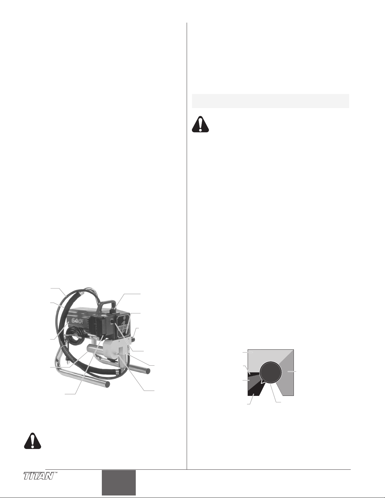
Table des matières
Flexible
de siphon
Moteur
Filtre
Flexible
de retour
CommutateurCommutateur
régulation de
la pression
Bouton de
régulation de
la pression
Cuvette
de lubrifiant
AMORÇ
VAPORISATION
Soupape
AMORÇAGE/
VAPORISATION
Section
des
liquides
Raccord
Disjoncteur
Clean
Min.
PSI
Max.
PSI
Nettoyage par
pulsations
(Turbo PulseClean,
zone rouge)
Arrêt
(OFF, zone noire)
Min. – 1 800 lb/po2
(Min, zone jaune)
1 800 à 3 200 lb/po2
(zone verte)
Arrêt
(OFF, zone noire)
Bouton de régulation
de pression
Consignes de sécurité.........................................................14
Description générale............................................................16
Fonctionnement ...................................................................16
Vérifications préliminaires...................................................16
Préparation avant de peindre .............................................17
Peinture ..............................................................................17
Indicateurs de pression ......................................................18
Procédure de décompression.............................................18
Vaporisation..........................................................................18
Technique de vaporisation ..................................................18
Essais préliminaires............................................................19
Nettoyage ..............................................................................19
Maintenance..........................................................................20
Généralités concernant la maintenance.............................20
Remplacement des filtres ...................................................20
Remplacement du moteur ..................................................21
Remplacement des balais de moteur.................................21
Remplacement des engrenages.........................................21
Remplacement du transducteur .........................................21
Remplacement de la soupape AMORÇAGE/VAPORISATION..22
Maintenance de la section des liquides..............................22
Dépannage ............................................................................24
Garantie.................................................................................25
Listes de pièces ...................................................................38
Corps de l’appareil..............................................................38
Moteur.................................................................................39
Boîte d’engrenages.............................................................40
Section des liquides............................................................42
Bloc d’aspiration .................................................................44
Support ...............................................................................44
Basse chariot .............................................................................45
Chariot........................................................................................46
Tube siphon (Chariot).........................................................46
Accessoires ........................................................................47
Schéma de raccordement électrique..................................49
Description générale
Ce vaporisateur à dépression est un outil électrique de
précision servant à atomiser divers types de matériaux. On
doit lire et suivre attentivement les directives apparaissant
dans ce manuel pour savoir comment l’utiliser et le maintenir
en bon ordre, et ce, en toute sécurité.
Vérifications préliminaires
On doit procéder aux étapes suivantes avant de brancher le
cordon d’alimentation de l’appareil.
1. Vérifier que le flexible d'aspiration/du siphon et le flexible
de retour sont bien fixés.
2. À l'aide d'une clé fixer un flexible de vaporisation sans air
en nylon de 1/4" d'au moins 15m de long sur l'appareil.
Serrer fermement.
3. Fixer un pistolet de vaporisation sans air au flexible de
vaporisation. À l'aide de deux clés (une sur le pistolet et
une sur le flexible), serrer fortement.
NOTA: Ne pas encore fixer l'embout sur le pistolet de
4. S’assurer que le bouton de régulation de pression soit à la
5.
6. Verser 15 ml (une cuillère à table) de lubrifiant pour joint
IMPORTANT : Ne jamais faire fonctionner l’appareil sans
liquide pendant plus de 10 secondes, ce qui pourrait user
inutilement les tampons graisseurs.
7. S’assurer que l’alimentation électrique soit d’au moins 15
8. Brancher le cordon d’alimentation dans une prise
IMPORTANT : Les rallonges utilisées doivent être trifilaires, de
calibre 12 et dotées d’une fiche à broche de MALT; on ne doit
jamais retirer cette troisième broche ou utiliser un adaptateur.
Préparation d’un nouveau vaporisateur
Si cet appareil est neuf, il contient encore un liquide d’essai
mis en usine pour le protéger de la corrosion en cours
d’expédition ou d’entreposage. Ce liquide doit être
complètement éliminé au moyen d’essence minérale avant
que l’appareil puisse être utilisé.
IMPORTANT : La détente du pistolet doit toujours être
verrouillée lorsqu’on procède à ces vérifications préliminaires.
1. Placez le flexible d'aspiration dans un récipient contenant
2. Mettre le flexible de retour dans un contenant de purge
3. Régler la pression au minimum en mettant le bouton de
vaporisation. Démonter l'embout s'il est déjà fixé.
S’assurer que tous les flexibles et pistolets à
dépression soit mis à la terre et conçus pour
accepter des pressions de liquide d’au moins 3
200 lb/po2 (22,1 MPa).
position OFF (zone noire).
S’assurer que le commutateur soit à la position OFF.
de piston (Piston Lube) dans la cuvette.
A
à 120 V.
adéquatement mise à la terre située à une distance d’au
moins 7,5 m (25 pi) de la surface à vaporiser.
de l'essence minérale avec un point d'inflammation au
moins égal à 60ºC.
métallique.
régulation à la position Min (zone jaune).
Fonctionnement
Cet appareil produit un jet à très haute pression;
avant de le faire fonctionner, il est donc essentiel
de lire et de comprendre les avertissements
formulés dans la section Consignes de sécurité à
l’avant de ce manuel.
Français
4. Abaisser la soupape AMORÇAGE/VAPORISATION à la
position PRIME.
5. Mettre l’appareil en marche en mettant le commutateur à
la position ON.
6. Laisser le vaporisateur fonctionner pendant 15 à 30
secondes pour évacuer le liquide d’essai par le flexible de
retour, jusqu’au contenant de purge.
7. Arrêter l’appareil en mettant le commutateur à la position OFF.
16 © Titan Tool Inc. Tous droits réservés.
Page 17

Préparation avant de peindre
Détente verrouillée.
Max.
PSI
Clean
Min.
PSI
Détente verrouillée.
Max.
PSI
Clean
Min.
PSI
Avant de peindre, il est important de s’assurer que le liquide
dans l’appareil est compatible avec le produit à utiliser.
NOTA: L’incompatibilité liquide/produit peut provoquer
IMPORTANT : La détente du pistolet doit toujours être
verrouillée lorsqu’on procède à ces vérifications
préliminaires.
1. Placez le flexible d'aspiration dans un récipient contenant
2.
3. Régler la pression au minimum en mettant
4. Abaisser la soupape AMORÇAGE/
5. Mettre l’appareil en marche en mettant le
6. Laisser le vaporisateur fonctionner pendant 15 à 30
7. Arrêter l’appareil en mettant le commutateur à la position
NOTA: S’assurer que l’embout ou le protège-embout
8. Soulever la soupape AMORÇAGE/VAPORISATION à la
9. Mettre l’appareil en marche.
10. Déverrouiller le pistolet en mettant le verrou de détente à
11. Appuyer sur la détente en visant le contenant métallique
12. Verrouiller le pistolet en mettant le
13.
14. Inspecter tous les composants afin d’y détecter des fuites
15. Procéder aux étapes de la section Procédure de
le blocage des soupapes, ce qui entraînerait le
besoin de démonter et de nettoyer la section des
liquides du vaporisateur.
le solvant approprié (consultez les consignes du
fabricant). Par exemple, l'eau est le solvant adapté pour
la peinture au latex.
Mettre le flexible de retour dans un contenant de purge
métallique.
le bouton de régulation à la position Min
(zone jaune).
VAPORISATION à la position PRIME.
commutateur à la position ON.
secondes pour évacuer le solvant usé par le flexible de
retour, jusqu’au contenant de purge.
OFF.
ne soient pas installés.
position SPRAY.
la position appropriée.
On doit mettre le pistolet à la
terre en le tenant contre le bord
du contenant de purge
métallique pendant qu’il se
vide afin d’éviter les risques de
décharges électrostatiques,
lesquelles peuvent provoquer un incendie.
pour purger le solvant usé du pistolet, jusqu’à ce que du
solvant frais en ressorte.
verrou de détente à la position
appropriée.
Déposer le pistolet et augmenter la
pression en tournant lentement le
bouton de régulation vers la droite,
jusqu’à la zone verte.
potentielles. Le cas échéant, suivre les directives de la
section Procédure de décompression du présent manuel
avant de fixer les flexibles et de serrer les raccords.
décompression du présent manuel avant de passer du
solvant au produit de peinture.
On doit effectuer la procédure de décompression
chaque fois qu’on arrête l’appareil pour en faire la
maintenance, en changer les réglages de
vaporisation, en remplacer/ nettoyer les embouts
ou en effectuer la préparation en vue d’un
nettoyage.
Peinture
1. Mettre le flexible d’aspiration dans un contenant de
produit de peinture.
2. Mettre le flexible de retour dans un contenant de purge
métallique.
3. Régler la pression au minimum en mettant
le bouton de régulation à la position Min
(zone jaune).
4. Abaisser la soupape
AMORÇAGE/VAPORISATION à la
position PRIME.
5. Mettre l’appareil en marche en mettant le commutateur à
la position ON.
6. Laisser le vaporisateur fonctionner jusqu’à ce que le
produit commence à s’écouler par le flexible de retour
dans le contenant de purge.
7. Arrêter l’appareil en mettant le commutateur à la position
OFF.
8. Retirer le flexible de retour du contenant de purge et le
mettre à sa position normale, au-dessus du contenant de
produit de peinture.
9. Soulever la soupape AMORÇAGE/VAPORISATION à la
position SPRAY.
10. Mettre l’appareil en marche.
11. Déverrouiller le pistolet en mettant le verrou de détente à
la position appropriée.
On doit mettre le pistolet à la
terre en le tenant contre le bord
du contenant de purge
métallique pendant qu’il se
vide afin d’éviter les risques de
décharges électrostatiques,
lesquelles peuvent provoquer un incendie.
12. Appuyer sur la détente en visant le contenant métallique
pour purger le solvant et l’air du flexible de vaporisation,
jusqu’à ce que le produit de peinture s’écoule librement du
pistolet.
13.
Verrouiller le pistolet en mettant le
verrou de détente à la position
appropriée.
14. Arrêter l’appareil.
15. Fixer l’embout et le protège-embout
au pistolet, conformément aux
directives accompagnant ces
derniers.
RISQUES D’INJECTION. Ne pas vaporiser sans
avoir installé le protège-embout. Ne jamais
appuyer sur la détente sans avoir mis l’embout en
position de vaporisation ou de désobstruction.
T
oujours enclencher le verrou de détente avant de
retirer, de remplacer ou de nettoyer l’embout.
16. Mettre l’appareil en marche.
17.
Augmenter la pression en tournant lentement le bouton de
régulation vers la droite, jusqu’à la zone verte, puis
effectuer un essais sur un morceau de carton en
examinant le jet résultant. Régler la pression de manière à
ce que le produit soit parfaitement atomisé. Essayer de
laisser le bouton de régulation au niveau du réglage
minimum pour conserver une bonne atomisation.
NOTA: Si la pression est trop élevée, l’embout subira
une usure prématurée et produira des
éclaboussures de surpulvérisation.
© Titan Tool Inc. Tous droits réservés. 17
Français
Page 18

Indicateurs de pression
Indicateur
de pression
Indicateur de marche du moteur
Port de programmation
Pare-poussière du port
de programmation
Jaune clignotant = 0 lb/po2
à la pression d’amorçage
Jaune continu = pression
d’amorçage à 1 800 lb/po2
Vert continu =
1 800 à 3 200 lb/po2
Disjoncteur
Détente verrouillée.
Voici une description des indicateurs du régulateur de pression
électronique (RPÉ).
Indicateur de Pression
L'indicateur de pression affiche la pression de travail actuelle
du vaporisateur. Il a trois niveaux d'indication : jaune
clignotant, jaune fixe et vert fixe.
Jaune Clignotant
Lorsque l'indicateur de pression est jaune clignotant, l’appareil
fonctionne à une pression comprise entre 0 et 200 PSI. Un
indicateur de pression jaune clignotant signifie :
• Que l’appareil est branché et en position "MARCHE".
• L’appareilest à une pression d'amorçage (peu ou pas de
pression)
• Il est possible sans danger de placer la soupape
AMORÇAGE/VAPORISATION entre deux positions.
• Il est possible et sans danger de changer ou de remplacer
l'embout de vaporisation (consulter le manuel de l'embout
concernant les procédures de remplacement).
NOTA: Si l'indicateur de pression commence à
Jaune Fixe
Lorsque l'indicateur de pression est jaune fixe, l’appareil
fonctionne à une pression comprise entre 200 et 1800 PSI.
Un indicateur de pression jaune fixe signifie :
Vert Fixe
Lorsque l'indicateur de pression est vert fixe, l’appareil
fonctionne à une pression comprise entre 1800 et 3200 PSI.
Un indicateur de pression vert fixe signifie :
clignoter en jaune lorsque le bouton de
commande de la pression est réglé sur une
pression supérieure et que la soupape
d'AMORÇAGE/VAPORISATION est en position
VAPORISATION, soit l'embout de vaporisation
est usé, soit il y a une fuite, soit l’appareil doit
être entretenu/réparé.
•
Que l’appareil est à la bonne pression pour vaporiser de
la teinture, de la laque, du vernis et des peintures
multicolores.
• Si l'indicateur de pression passe au jaune fixe lorsque la
pression est réglée pour démarrer en vert fixe, cela
signifie l'un des points suivants :
a. Indicateur d'Usure d'Embout – lors de la vaporisation
avec du latex ou à haute pression, le jaune fixe apparaît.
Ceci signifie que l'embout est usé et doit être remplacé.
b. Embout Trop Grand – lorsqu'un embout est trop grand
pour l’appareil est installé sur le pistolet, l'indicateur de
pression passe de vert fixe à jaune fixe.
c. Usure de la Section des Fluides – si un indicateur de
pression jaune fixe apparaît lorsqu'on utilise un nouvel
embout et que la pression est réglée au maximum, il
est peut être nécessaire de réparer l’appareil (tampons
graisseurs usés, piston usé, soupape collée, etc).
• L’appareil est réglé sur la bonne pression pour vaporiser
des peintures d'intérieur à l'huile ou au latex.
• L’appareil fonctionne à plein régime avec une pression
élevée.
Français
Indicateur de Fonctionnement du Moteur
L'indicateur de Fonctionnement du Moteur est allumé lorsque
le moteur est mis en marche. Cet indicateur est utilisé par les
centres techniques pour réparer les problèmes de moteur.
Procédure de décompression
On doit effectuer la procédure de décompression
chaque fois qu’on arrête l’appareil pour en faire la
maintenance, en changer les réglages de
vaporisation, en remplacer/ nettoyer les embouts
ou en effectuer la préparation en vue d’un
nettoyage.
1. Verrouiller le pistolet en mettant le
verrou de détente à la position
appropriée.
2.
Arrêter l’appareil en mettant le
commutateur à la position OFF.
3. Tourner le bouton de régulation de la
pression vers la gauche, jusqu’à la
position OFF, dans la zone noire.
4. Déverrouiller le pistolet en mettant le verrou de détente à
la position appropriée.
5. Tenir fermement la partie métallique du
pistolet contre le bord d’un contenant
métallique afin d’éviter une accumulation
d’électricité statique.
6. Appuyer sur la détente du pistolet afin de
purger tout l’air restant dans le flexible.
7. Verrouiller le pistolet en mettant le verrou de détente à la
position appropriée.
8. Abaisser la soupape AMORÇAGE/VAPORISATION à la
position PRIME.
Vaporisation
RISQUES D’INJECTION. Ne pas vaporiser sans
avoir installé le protège-embout. Ne jamais appuyer
sur la détente sans avoir mis l’embout en position
de vaporisation ou de désobstruction. Toujours
enclencher le verrou de détente avant de retirer, de
remplacer ou de nettoyer l’embout.
Technique de vaporisation
En suivant les techniques suivantes, on s’assure d’obtenir des
résultats d’allure professionnelle.
Tenir le pistolet perpendiculairement par rapport à la surface,
toujours à la même distance de cette dernière (selon le produit
utilisé, la surface en présence et la forme de jet désirée, cette
distance devrait se situer entre 30 et 35 cm [12 et 14 po]).
Procéder verticalement ou horizontalement à un rythme
régulier, ce qui aura pour effet de minimiser le gaspillage de
produit et d’assurer une couverture égale. Le rythme idéal
permet d’appliquer une couche chargée sur toute la surface,
sans gouttes ni coulées.
En tenant le pistolet plus près de la surface, on y applique
davantage de produit, mais sur une bande plus étroite, tandis
qu’en l’éloignant, on obtient une couche moins épaisse,
répartie sur une plus grande largeur. En présence de gouttes,
de coulées ou de surpulvérisation, on doit opter pour un
embout doté d’un plus petit orifice; s’il n’y a pas assez de
produit sur la surface, ou si on désire procéder plus
rapidement, il est préférable de choisir un embout à orifice
plus grand.
On doit procéder par gestes réguliers et uniformes, en inversant
les mouvements à chaque passage (de haut en bas, puis de
bas en haut, ou de gauche à droite, puis de droite à gauche).
Amorcer le mouvement avant d’appuyer sur la détente.
18 © Titan Tool Inc. Tous droits réservés.
Page 19

Il faut éviter de procéder par gestes semi-circulaires ou
Bords chevauchants
1
er
passage
2
e
passage
3
e
passage
4
e
passage
5
e
passage
Trop épais
Vaporisation
hors cible
Mouvements semi-circulaires Pistolet incliné
Amorcer le
mouvement
Relâcher
la détente
Appuyer sur
la détente
Terminer le
mouvement
Min.
PSI
Max.
PSI
Clean
Jet efficace
Traînées de produit
d’incliner le pistolet par rapport à la surface, ce qui produirait
un fini inégal.
Il est essentiel de faire chevaucher chacun des passages pour
obtenir un fini uniforme. Si, par exemple, on procède
horizontalement, il faut commencer par le haut, puis viser le
bord inférieur du passage précédent de manière à en
chevaucher la moitié.
Lorsqu’on utilise un écran protecteur, celui-ci doit être
fermement maintenu contre la surface. Le pistolet doit être
légèrement incliné de manière à éloigner le jet de l’écran, ce qui
évitera de faire pénétrer le produit de peinture sous ce dernier.
On doit également protéger les arbustes près des bâtiments en
les attachant et en les couvrant d’une toile. Cette toile doit
cependant être retirée dans les plus brefs délais. Les rallonges
de pistolet Titan peuvent, elles aussi, s’avérer fort utiles dans de
telles situations.
Les objets comme les voitures, l’ameublement de jardin, etc.
doivent être éloignés ou recouverts lorsqu’ils sont à proximité de la
surface à vaporiser. Il faut toujours s’assurer de protéger les
éléments susceptibles d’être endommagés par des éclaboussures.
Essais préliminaires
1. S’assurer que le flexible à produit de peinture soit exempt
de coudes et éloigné de toute arête coupante.
2. Tourner le bouton de régulation de pression à son réglage
le plus bas.
3. Soulever la soupape AMORÇAGE/VAPORISATION à la
position SPRAY.
© Titan Tool Inc. Tous droits réservés. 19
4. Tourner le bouton de régulation de pression à son réglage
le plus élevé; le flexible à produit devrait se raidir sous
l’effet de la pression.
5. Déverrouiller la détente du pistolet.
6. Appuyer sur la détente pour évacuer l’air du flexible.
7. Quand la peinture atteint l’embout, effectuer un essai de
vaporisation en vue de régler le jet en fonction du travail à
effectuer.
8. Régler la pression au niveau
le plus bas qui permette
d’obtenir le jet désiré. Si la
pression est trop élevée, le jet
sera trop dispersé; si elle est
trop basse, le jet produira des
traînées ou crachera des
grumeaux de produit.
Nettoyage
Directives particulières pour le nettoyage au
moyen de solvants inflammables :
• Purger le pistolet à l’extérieur de préférence, à une
distance d’au moins une longueur de flexible de la pompe.
• Si le solvant usé est recueilli dans un contenant
métallique de 4 litres (1 gallon), celui-ci doit être inséré
dans un second contenant d’au moins 20 litres (5 gallons).
• L’endroit choisi doit être exempt de vapeurs inflammables.
• On doit suivre les directives de nettoyage à la lettre.
IMPORTANT : Le vaporisateur, le flexible et le pistolet
doivent être nettoyés en profondeur après chaque journée
d’utilisation et ce, afin d’éviter les accumulations de
produit susceptibles de nuire grandement au rendement
de l’appareil.
Lorsqu’on se sert d’essence minérale ou d’autres
solvants pour nettoyer le vaporisateur, le flexible ou le
pistolet, on doit régler la pression au minimum et
retirer l’embout de la buse du pistolet. L’accumulation
d’électricité statique risque de provoquer des
incendies en présence de vapeurs inflammables.
1. Suivre la Procédure de décompression à la section
Fonctionnement du présent manuel.
Retirer l’embout et le protège-embout, et les nettoyer au
2.
moyen d’une brosse et du solvant approprié.
3. Placez le flexible d'aspiration dans un récipient contenant le
solvant approprié (consultez les consignes du fabricant). Par
exemple, l'eau est le solvant adapté pour la peinture au latex.
4. Mettre le flexible de retour dans un contenant de purge
métallique.
5. Abaisser la soupape AMORÇAGE/VAPORISATION à la
position PRIME.
6. Régler la pression pour le nettoyage par
pulsations en mettant le bouton de
régulation à la position CLEAN (zone rouge).
7. Mettre l’appareil en marche en mettant le
commutateur à la position ON.
8. Laisser le solvant circuler dans l’appareil
pour évacuer le produit de peinture par le
flexible de retour, jusqu’au contenant de purge.
9. Arrêter l’appareil en mettant le commutateur à la position OFF.
10. Soulever la soupape AMORÇAGE/VAPORISATION à la
position SPRAY.
11. Mettre l’appareil en marche.
On doit mettre le pistolet à la terre en
le tenant contre le bord du contenant
de purge métallique pendant qu’il se
vide afin d’éviter les risques de
décharges électrostatiques,
lesquelles peuvent provoquer un incendie.
12. Appuyer sur la détente en visant le contenant métallique
Français
Page 20

pour purger le produit du flexible, jusqu’à ce que le
Corps du pistolet
Joint
de la poignée
Filtre
Poignée
Bloc pompe
Joint Torique
Filtre
Adaptateur
Ressort du support de filtre
Ressort du filtre
Logement du filtre
solvant s’écoule du pistolet.
13. Continuer d’appuyer sur la détente, en direction du
contenant métallique, jusqu’à ce que le solvant évacué
soit propre.
NOTA: Pour l’entreposage à long terme en milieu froid,
14. Suivre la Procédure de décompression à la section
15. Débrancher l’appareil et le ranger dans un endroit propre
IMPORTANT : Ne pas ranger l’appareil sous pression.
remplir tous les composants de l’appareil
d’essence minérale.
Dans le cas de rangement à court terme après
utilisation de peinture au latex, remplir tous les
composants d’eau mélangée au protecteur
Titan Liquid Shield (se reporter à la section
Accessoires du présent manuel pour obtenir le
numéro de pièce de ce produit).
Fonctionnement du présent manuel.
et sec.
Maintenance
Avant de procéder, on doit suivre les directives de
la section Procédure de décompression du
présent manuel. On doit également respecter tous
les autres avertissements si on veut éviter les
blessures par injection, par contact avec une
pièce mobile ou par choc électrique. Le
vaporisateur doit toujours être débranché avant
d’être entretenu ou réparé.
Généralités concernant la maintenance
Pour réparer ou entretenir le vaporisateur, on pourrait avoir à
recourir aux outils suivants :
Tournevis étoile Clé hexagonale de 1,0 cm (3/8 po)
Pince à bec pointu Clé hexagonale de 0,8 cm (5/16 po)
Clé à ouverture variable Clé hexagonale de 0,6 cm (1/4 po)
Maillet en caoutchouc Clé hexagonale de 0,5 cm (3/16 po)
Tournevis plat Clé hexagonale de 0,4 cm (5/32 po)
1. Avant de procéder à la maintenance de n’importe quel
composant du vaporisateur, il faut lire attentivement les
directives ainsi que tous les avertissements qu’elles
contiennent.
IMPORTANT : Ne jamais tirer sur le cordon pour le
débrancher
2. Vérifier les résultats de la maintenance effectuée avant
d’utiliser le vaporisateur en conditions normales afin de
s’assurer que le problème ait bel et bien été corrigé. Si le
vaporisateur ne fonctionne toujours pas comme il faut,
repasser la procédure pour s’assurer qu’elle ait été bien
suivie. Se reporter ensuite à la section Dépannage pour
cerner la source potentielle du problème.
3. S’assurer que l’endroit choisi soit bien ventilé si des
solvants sont utilisés pour le nettoyage. Toujours porter
des lunettes de protection lorsqu’on procède à la
maintenance. D’autres dispositifs protecteurs pourraient
être requis selon le type de solvant utilisé; on doit toujours
communiquer avec le fabricant de ce dernier pour obtenir
ses recommandations à cet effet.
4. Pour toute autre question relative à ce vaporisateur à
dépression, il suffit de communiquer avec Titan :
Service à la clientèle (É.-U.)..................1-800-526-5362
Service à la clientèle (Canada) .............1-800-565-8665
Service à la clientèle (international) ......1-201-337-1240
, ce qui pourrait détacher le connecteur des fils.
Télécopieur.....................................1-800-528-4826
Télécopieur.................................... 1-905-856-8496
Télécopieur ....................................1-201-405-7449
Remplacement des filtres
Filtre de pompe
1. Dégager et retirer manuellement le logement du filtre.
2. Glisser le filtre afin de le dégager du ressort du support de
filtre.
3. Inspecter le filtre; le nettoyer ou le remplacer au besoin.
4. Inspecter le joint torique; le nettoyer ou le remplacer au
besoin.
5. Glisser le filtre neuf ou nettoyé sur le ressort du support
de filtre (s’assurer que l’adaptateur est bien en place).
Pousser le filtre jusqu’au centre du bloc pompe.
6. Glisser le logement sur le filtre et le visser solidement sur
le bloc pompe.
NOTA: On doit serrer manuellement le logement du
filtre, en s’assurant qu’il est installé
fermement dans le bloc pompe.
Filtre de pistolet
1. Déverrouiller la détente du pistolet.
2. Dégager et retirer la poignée du corps du pistolet.
3. En tournant vers la droite, dévisser le filtre du corps.
NOTA: Le filetage à gauche requiert qu’on tourne vers
la droite pour dévisser.
4. En tournant vers la gauche, visser le filtre nettoyé ou de
rechange sur le corps.
5. S’assurer que le joint de la poignée soit bien placé et
visser solidement cette dernière sur le corps.
6. Verrouiller la détente du pistolet.
NOTA: Pour obtenir plus de détails, se renseigner sur
les numéros de pièce ou voir des dessins
d’assemblage à plus grande échelle, se reporter
au manuel de l’utilisateur du pistolet à
dépression professionnel LX -80 II (no 313-2069).
Français
20 © Titan Tool Inc. Tous droits réservés.
Page 21

Remplacement du moteur
Carter
du moteur
Couvercle des balais
Moteur
Vis de montage
du moteur
Logement de la pompe
Condensateurs
Coquille
Vis de la coquille
Vis du carter du moteur
NOIR
BLACKNOIR
ROUGEROUGE
NOIR
ROUGE
ROUGE
RED
BLACK
Couvercle avant
Logement de la pompe
Vis du couvercle avant
Second engrenage
Rondelles de butée
Vis de montage
du moteur
Assemblage
engrenages/vilebrequin
Engrenage d’armature
Moteur
Carter du moteur
Vis du carter du moteur
1. Débrancher l’appareil.
2. Desserrer et retirer les quatre vis du carter de moteur et
retirer ce premier.
3. Déconnecter du moteur les fils noirs et rouges provenant
du logement de la pompe et des condensateurs.
4. Retirer les condensateurs de leur agrafe de montage.
5. Desserrer et retirer les quatre vis de montage du moteur.
6. Retirer le moteur du logement de la pompe.
NOTA: Si le moteur refuse de sortir du logement de la
pompe :
• Retirer le couvercle avant.
• Au moyen d’un maillet en caoutchouc,
donner de petits coups à l’avant du
vilebrequin (qui ressort de la bielle).
7. Une fois le moteur retiré, inspecter les engrenages dans
le logement de la pompe pour y détecter d’éventuels
dommages ou une usure excessive. Les remplacer, le cas
échéant.
8. Installer le nouveau moteur dans le logement de la
pompe.
NOTA: Faire tourner manuellement le ventilateur du
moteur jusqu’à ce que l’engrenage d’armature
entre en prise avec celui du logement de la
pompe.
9. Fixer le moteur au moyen des quatre vis de montage.
10. Enclipser les condensateurs sur leurs agrafes respectives.
11. Reconnecter les fils (se reporter au schéma de
raccordement électrique de la section Listes de pièces du
présent manuel).
12. Glisser le carter sur le moteur en le fixant au moyen des
quatre vis prévues.
Remplacement des engrenages
1. Desserrer et retirer les quatre vis du carter de moteur et
retirer ce premier.
2. Déconnecter les fils rouge et noir provenant du logement
de la pompe.
3. Desserrer et retirer les quatre vis de montage du moteur.
4. Retirer le moteur du logement de la pompe.
NOTA: Si le moteur refuse de sortir du logement de la
pompe :
• Retirer le couvercle avant.
• Au moyen d’un maillet en caoutchouc,
donner de petits coups à l’avant du
vilebrequin (qui ressort de la bielle).
7. Inspecter l’engrenage d’armature à l’extrémité du moteur
pour y détecter d’éventuels dommages ou une usure
excessive. Si cet engrenage est complètement usé,
remplacer tout le moteur.
8. Retirer et inspecter le second engrenage pour y détecter
d’éventuels dommages ou une usure excessive. Le
remplacer, le cas échéant.
9. Retirer et inspecter l’assemblage engrenages/vilebrequin
pour y détecter d’éventuels dommages ou une usure
excessive. Le remplacer, le cas échéant.
10. Remonter la pompe en reprenant les étapes ci-dessus à
l’envers, en s’assurant que les rondelles de butée restent
bien en place.
NOTA: Verser environ 150 ml (5 oz) de Lubriplate (no
314-171) dans la boîte d’engrenages.
Remplacement des balais de moteur
Pour effectuer cette procédure, on doit se procurer une
trousse de remplacement des balais de moteur (no 704-276).
1. Desserrer et retirer les quatre vis du carter de moteur et
retirer ce premier.
2. Desserrer et retirer les deux vis de la coquille et retirer
cette dernière.
3. Au moyen d’un petit tournevis, disjoindre les deux
couvercles de balai en plastique.
4. Déconnecter les fils rouges et noirs des balais et retirer
ces derniers.
5. Installer les nouveaux balais et enclipser les couvercles
en plastique.
6. Reconnecter les fils rouges et noirs des balais (se reporter
au schéma de raccordement électrique de la section
Listes de pièces du présent manuel).
7. Mettre la coquille au-dessus du ventilateur du moteur et la
fixer au moyen des deux vis prévues.
8. Glisser le carter sur le moteur en le fixant au moyen des
quatre vis prévues.
© Titan Tool Inc. Tous droits réservés. 21
Remplacement du transducteur
1. Desserrer et retirer les quatre vis du couvercle avant et
retirer ce dernier.
2. Arrêter le vaporisateur en le bas de course afin que le
piston soit à sa position la plus basse. Débrancher
l’appareil.
Avant de procéder, on doit suivre les directives de
la section Procédure de décompression du
présent manuel. On doit également respecter tous
les autres avertissements si on veut éviter les
blessures par injection, par contact avec une
pièce mobile ou par choc électrique. Le
vaporisateur doit toujours être débranché avant
d’être entretenu ou réparé.
Français
Page 22

3. Incliner la pompe vers l’arrière pour accéder plus
Rainure en T
Logement
de la
pompe
Bloc
pompe
Vis de
montage
du bloc
pompe
Couvercle
avant
Vis
de montage
du RPÉ
Régulateur
de pression
électronique
(RPÉ)
Vis du
couvercle
avant
Vis de fixation
Transducteur
Joint d’étanchéité
Base à came
Tige de la soupape
Bloc pompe
Logement
de la soupape
Manette
de la
soupape
Goupille
facilement à la section des liquides.
4. Au moyen d’une clé hexagonale de 1,0 cm, desserrer et
retirer les deux vis de montage du bloc pompe.
5. Tirer sur le bloc pompe afin de le faire ressortir d’environ
1,5 cm (1/2 po) de son logement, de manière à dégager le
transducteur.
6. Glisser le bloc pompe et la tige du piston vers l’avant
jusqu’à ce que cette dernière sorte de la rainure en T de
la bielle.
7. Desserrer et retirer les quatre vis de montage du RPÉ
(régulateur de pression électronique)
8. Écarter le RPÉ de manière à pouvoir accéder au
connecteur du transducteur.
9. Déconnecter le transducteur de l’emplacement JP3 du
tableau du RPÉ (se reporter au schéma de raccordement
électrique de la section Listes de pièces du présent
manuel).
10. Au moyen d’une clé hexagonale de 0,3 cm (1/8 po),
desserrer et retirer la vis de fixation de la partie inférieure
du logement de la pompe.
11. Glisser le transducteur hors de cette partie inférieure.
12. Installer le nouveau transducteur dans le logement de la
pompe.
13. Insérer et serrer fermement la vis de fixation dans la
partie inférieure.
14. Connecter le transducteur dans l’emplacement JP3 du
tableau du RPÉ (se reporter au schéma de raccordement
électrique de la section Listes de pièces du présent
manuel).
15. Remonter la pompe en reprenant les étapes 1 à 8 à
l’envers.
Remplacement de la soupape
AMORÇAGE/VAPORISATION
Pour effectuer cette procédure, on doit se procurer une
trousse de remplacement de soupape AMORÇAGE/
VAPORISATION (no 700-258).
1. Pousser la goupille hors de la manette de la soupape
2. Retirer la manette et la base à came.
3. Au moyen d’une clé, desserrer et retirer le logement de la
soupape.
4. S’assurer que le joint d’étanchéité soit à sa place, et
visser le nouveau logement dans le bloc pompe; serrer
fermement à l’aide d’une clé.
5. Mettre la base à came par dessus le logement de la
soupape; la lubrifier au moyen de graisse et aligner la
came avec le bloc pompe.
6. Aligner le trou dans la tige de soupape avec celui de la
manette.
7. Insérer la goupille à travers ces deux trous afin de fixer la
manette en place.
IMPORTANT : Afin d’éviter d’endommager le joint
d’étanchéité du transducteur
correctement aligné avec le trou du bloc pompe.
, s’assurer que ce dernier soit
Maintenance de la section des liquides
On doit suivre les procédures suivantes pour effectuer la
maintenance des soupapes et remplacer les tampons
graisseurs de la section des liquides. Au préalable, il est
cependant important de procéder aux étapes ci-dessous.
1. Desserrer et retirer les quatre vis du couvercle avant et
retirer ce dernier.
2. Arrêter le vaporisateur en le bas de course afin que le
piston soit à sa position la plus basse. Débrancher
l’appareil.
Avant de procéder, on doit suivre les directives de
la section Procédure de décompression du
présent manuel. On doit également respecter tous
les autres avertissements si on veut éviter les
blessures par injection, par contact avec une
pièce mobile ou par choc électrique. Le
vaporisateur doit toujours être débranché avant
d’être entretenu ou réparé.
3. Dévisser le flexible de retour du bloc pompe.
4. Retirer l’agrafe qui fixe le bloc d’aspiration à la soupape
de retenue; disjoindre ces éléments.
5. Incliner la pompe vers l’arrière pour accéder plus
facilement à la section des liquides.
Français
22 © Titan Tool Inc. Tous droits réservés.
Page 23

Maintenance des soupapes
Bielle
Écrou de
retenue
Guidepiston
Tampon
supérieur
Bloc
pompe
Tampons
inférieurs
Vis de
montage
du bloc
pompe
Tige du
piston
Rainure
en T
Joint
d’étanchéité
du transducteur
Logement de
la soupape
de sortie
Siège de
la soupape
de sortie
Clapet de
la soupape
de sortie
Cage supérieure
Joint supérieur
Tige du piston
Joint torique
Logement de
la soupape
de retenue
Siège de
la soupape
de retenue
Clapet de
la soupape
de retenue
Manchon
Joint torique
Cage inférieure
Joint inférieur
La partie surélevée et le
joint torique des tampons
inférieurs doivent être
vers le haut.
La partie surélevée et le
joint torique du tampon
supérieur doivent être
vers le bas.
Joint torique
Joint torique
Partie surélevée
Partie surélevée
La conception de la section des
liquides du vaporisateur Titan fait en
sorte qu’on peut accéder aux
soupapes de retenue et de sortie, de
même qu’à leur siège respectif, sans
avoir à démonter toute la section. Il
arrive que ces soupapes soient mal
assises à cause de débris
accumulés; en suivant les directives
ci-dessous, on peut les nettoyer et
inverser ou remplacer leur siège.
1. Au moyen d’une clé,
desserrer et retirer le
logement de la soupape de
retenue du bloc pompe.
2. Enlever tous les débris dans le logement et examiner les
composants; si le siège est endommagé, l’inverser ou le
remplacer.
3. À l’aide d’une clé hexagonale de 1,0 cm (3/8 po), dévisser
et retirer le logement de la soupape de sortie de la tige du
piston.
NOTA: La tige du piston doit
4. Enlever tous les débris dans le
logement et examiner les
composants; si le siège est
endommagé, l’inverser ou le
remplacer.
5. Retirer, nettoyer et inspecter la
cage et le clapet supérieurs; les remplacer s’ils sont usés
ou endommagés.
6. Remonter les soupapes en reprenant les étapes ci-dessus
à l’envers.
Remplacement des tampons graisseurs
NOTA: Les tampons installés en usine sont noirs,
1. Retirer les
soupapes de
retenue et de
sortie en suivant
les directives de
la section
Maintenance des
soupapes cidessus.
2. Au moyen d’une
clé hexagonale de
1,0 cm, desserrer
et retirer les deux
vis de montage
du bloc pompe.
3. Tirer sur le bloc
pompe afin de le
faire ressortir
d’environ 1,5 cm
de son logement.
4. Glisser le bloc
pompe et la tige
du piston vers
l’avant jusqu’à ce
que cette dernière
sorte de la rainure
en T de la bielle.
© Titan Tool Inc. Tous droits réservés. 23
toujours être
raccordée à la pompe
quand on effectue
l’entretien de la
soupape de sortie; ce
faisant, on évitera que
la tige pivote lorsqu’on
démonte la soupape.
tandis que ceux de rechange (dans la trousse
de remplacement) sont blancs.
5. Glisser la tige du piston hors de la partie inférieure du bloc
pompe.
6. Desserrer et retirer l’écrou de retenue et le guide-piston
du bloc pompe.
7. Retirer les tampons supérieur et inférieurs du bloc pompe.
8. Nettoyer le bloc pompe et installer les nouveaux tampons
supérieur et inférieurs (se reporter à l’illustration cidessous pour bien les orienter).
9. Inspecter la tige du piston pour y déceler toute trace
d’usure et la remplacer au besoin.
10. Remonter la soupape de sortie dans la tige du piston;
serrer fermement le logement au moyen d’une clé.
NOTA: Se servir de la rainure en T de la bielle pour
retenir la tige du piston quand on serre le
logement de la soupape.
IMPORTANT : On ne doit jamais se servir d’une clé pour
serrer le piston lui-même, ce qui pourrait l’endommager et
entraîner des fuites.
11. Insérer le guide-piston dans l’écrou de retenue et visser
fermement ce dernier à la main dans le bloc pompe.
Glisser l’outil guide-piston (inclus dans la trousse de
12.
remplacement des tampons) sur le dessus de la tige du
piston, puis insérer cette dernière dans la partie inférieure
du bloc pompe. À l’aide d’un maillet en caoutchouc,
donner de petits coups au bas de la tige jusqu’à ce qu’elle
reprenne sa place dans le bloc pompe.
NOTA: Enduire de graisse l’outil guide-piston et la
tige du piston avant de les insérer dans le bloc
pompe.
13. Au moyen d’une clé, serrer fermement l’écrou de retenue.
14. Glisser le haut de la tige du piston dans la rainure en T de
la bielle.
15. Positionner le bloc pompe sous son logement et l’y insérer
jusqu’au fond.
IMPORTANT : Afin d’éviter d’endommager le joint
d’étanchéité du transducteur
, s’assurer que ce dernier soit
correctement aligné avec le trou du bloc pompe.
16. Insérer les vis de montage du bloc pompe à travers ce
dernier et son logement; serrer fermement.
17. Remonter la soupape de retenue dans le bloc pompe.
18.
Insérer le coude du bloc d’aspiration dans la partie
inférieure de la soupape de retenue. Positionner l’agrafe
de retenue dans cette dernière de manière à fixer le bloc
d’aspiration.
19. Visser le flexible de retour dans le bloc pompe et serrer
fermement.
20. Mettre le couvercle avant sur le logement de la pompe et
le fixer au moyen des quatre vis prévues.
21. Mettre le vaporisateur en marche en suivant la procédure
indiquée dans la section Fonctionnement du présent
manuel pour s’assurer de l’absence de fuites.
NOTA: On peut se procurer une trousse de
remplacement des tampons graisseurs (no
730-401), laquelle contient les éléments qui
garantiront les meilleurs résultats pour cette
procédure.
Français
Page 24

Problème
L'appareil ne fonctionne pas.
Dépannage
Cause
1. L’appareil n'est pas branché.
2. Disjoncteur déclenché.
3. Le réglage de pression est trop bas (le
bouton de commande de la pression au
réglage minimum n'envoie pas de
puissance au vaporisateur).
4. Câblage défectueux ou débranché.
5. Température excessive du moteur.
6. Commutateur MARCHE/ARRÊT
défectueux.
Solution
1. Brancher l’appareil.
2. Réenclencher le disjoncteur.
3. Faire tourner le bouton de commande de la
pression pour alimenter l’appareil et
accroître la pression.
4. Vérifier ou le faire réparer dans un centre
d'entretien agrée par Titan.
5. Laisser le moteur refroidir.
6. Replacer le commutateur
MARCHE/ARRÊT.
L'appareil ne s'amorce pas.
La pression ne se fait pas
dans l'appareil ou la pression
n'est pas uniforme.
1. La soupape
d'AMORÇAGE/VAPORISATION est en
position VAPORISATION.
2. Fuite d'air dans le flexible du
siphon/d'aspiration.
3. Le filtre de la pompe et/ou le filtre
d'entrée sont bouchés.
4. Le flexible de siphon/d'aspiration est
bouché.
1. L'embout d'aspiration est usé.
2. L'embout d'aspiration est trop grand.
3. Le bouton de commande de la pression
n'est pas correctement fixé.
4. Le filtre de la pompe, le filtre du pistolet
ou le filtre d'entrée sont bouchés.
5. Du produit s'échappe du flexible de
retour lorsque la soupape
D'AMORÇAGE/VAPORISATION est en
position VAPORISATION.
6. Fuite d'air dans le flexible du siphon/le
flexible d'aspiration.
7. Il y a une fuite de liquide externe.
8. Il y a une fuite interne dans la section
des liquides (les tampons graisseurs
sont usés et/ou sales, les clapets sont
usés).
9. Sièges de soupape usés.
10. Le moteur démarre mais ne tourne pas.
1. Faire tourner la soupape
d'AMORÇAGE/VAPORISATION dans le
sens des aiguilles d'une montre en position
AMORÇAGE.
2. Vérifier le branchement du flexible du
siphon/d'aspiration et serrer ou recoller le
raccord avec du ruban en PTFE.
3. Démonter le filtre de la pompe et le
nettoyer. Démonter le filtre d'entrée et le
nettoyer.
4. Démonter le flexible du siphon/d'aspiration
et le nettoyer.
1. Remplacer l'embout d'aspiration selon les
consignes qui accompagnent le pistolet de
vaporisation.
2. Remplacer l'embout d'aspiration par un
embout à moins large selon les consignes
qui accompagnent le pistolet de
vaporisation.
3. Tourner le bouton dans le sens des aiguilles
d'une montre pour augmenter la pression.
4. Démonter le filtre de la pompe et le
nettoyer. Retirer le filtre du pistolet et le
nettoyer. Démonter le filtre d'entrée et le
nettoyer.
5. Nettoyer ou remplacer la soupape
d'AMORÇAGE/VAPORISATION.
6. Vérifier le branchement du flexible du
siphon/d'aspiration et serrer ou recoller le
raccord avec du ruban en PTFE.
7. Vérifier qu'il n'y a pas de fuites externes
dans tous les raccords. Resserrer les
raccords au besoin.
8. Nettoyer les soupapes et la section des
liquides selon la procédure "Maintenance
de la Section des Liquides" décrite au
chapitre Maintenance de ce manuel.
9. Inverser ou remplacer les sièges de
soupape selon la procédure "Maintenance
de la Section des Liquides" décrite au
chapitre Maintenance de ce manuel.
10. Faire réparer dans un centre d'entretien
agrée par Titan.
Fuite de liquide dans la partie
supérieure de la section des
liquides.
1. Les tampons graisseurs supérieurs
sont usés.
2. La tige du piston est usée.
Français
24 © Titan Tool Inc. Tous droits réservés.
1. Regarnir selon la procédure "Maintenance
de la Section des Liquides" décrite au
chapitre Maintenance de ce manuel.
2. Remplacer la tige du piston selon la
procédure "Maintenance de la Section des
Liquides" décrite au chapitre Maintenance
de ce manuel.
Page 25

Problème
Trop grand afflux au pistolet
vaporisateur.
Dépannage
Cause
1. Mauvais type de flexible de
vaporisation sans air.
2. L'embout d'aspiration est usé ou trop
grand.
3. Pression excessive.
Solution
1. Remplacer le flexible par un flexible de
vaporisation de peinture sans air en tresse
de textile de 1/4" et de 15m de longueur.
2. Remplacer l'embout d'aspiration selon les
consignes qui accompagnent le pistolet de
vaporisation.
3. Faire tourner le bouton de commande de la
pression dans le sens inverse des aiguilles
d'une montre pour réduire la pression
d'évaporation.
Forme de vaporisation
incorrecte.
1. L'embout d'aspiration est trop grand
pour le produit utilisé.
1. Remplacer l'embout d'aspiration par un
embout neuf ou plus petit selon les
consignes qui accompagnent le pistolet de
vaporisation.
2. Mauvais réglage de pression.
2. Faire tourner le bouton de commande de la
pression pour régler la pression sur une
forme de vaporisation plus adapter.
3. Sortie de liquide insuffisante.
3. Nettoyer toutes les crépines et tous les
filtres.
4. Le produit vaporisé est trop visqueux.
4. Ajouter du solvant au produit selon les
recommandations du fabricant.
L'outil n'est pas alimenté
électriquement.
1. Le réglage de la pression est trop
faible.
1. Faire tourner le bouton de commande de la
pression dans le sens des aiguilles d'une
montre pour augmenter la pression.
2. Mauvaise tension d'alimentation.
2. Rebrancher sur 120 V AC.
Garantie
Titan Tools, inc. (« Titan ») garantit qu’au moment de la livraison à l’acheteur original (« Utilisateur »), l’appareil couvert par la présente garantie sera
exempt de défauts de matériaux et de fabrication. Les responsabilités de Titan en vertu de cette garantie se limitent au remplacement ou à la réparation
sans frais des pièces dont on aura, à la satisfaction raisonnable de Titan, démontré la défectuosité dans un délai de vingt-cinq (25) mois après la date
d’achat par l’Utilisateur. Cette garantie ne s’applique que si l’appareil a été installé et utilisé conformément aux recommandations et directives de Titan.
Cette garantie ne s’applique pas dans les cas d’endommagement ou d’usure engendrés par de l’abrasion, de la corrosion, un mauvais usage, de la
négligence, un accident, une installation incorrecte, un remplacement par des composants non fournis par Titan ou toute intervention non autorisée apte à
nuire au fonctionnement normal de l’appareil.
Les pièces défectueuses doivent être envoyées à un centre de service/vente Titan autorisé; les frais de transport, incluant le retour à l’usine, le cas
échéant, doivent être défrayés à l’avance par l’Utilisateur. Une fois remplacées ou réparées, les pièces seront renvoyées à ce dernier par transport
prépayé.
AUCUNE AUTRE GARANTIE EXPLICITE N’EST DONNÉE. PAR LES PRÉSENTES, TITAN SE DÉGAGE DE TOUTE AUTRE GARANTIE IMPLICITE,
INCLUANT, SANS TOUTEFOIS S’Y LIMITER, LES GARANTIES DE COMMERCIABILITÉ ET D’ADAPTATION À UN USAGE PARTICULIER, DANS LES
LIMITES PERMISES PAR LA LOI. LA DURÉE DES GARANTIES IMPLICITES NE POUVANT ÊTRE DÉCLINÉES SE LIMITE À LA PÉRIODE INDIQUÉE
DANS LA GARANTIE EXPLICITE. LES RESPONSABILITÉS DE TITAN NE SAURAIENT EN AUCUN CAS SE CHIFFRER À UN MONTANT SUPÉRIEUR
À CELUI DU PRIX D’ACHAT, ET CELLES RELATIVES AUX DOMMAGES CONSÉCUTIFS, ACCESSOIRES OU PARTICULIERS EN VERTU DE TOUTE
GARANTIE SONT ÉGALEMENT DÉCLINÉES, DANS LES LIMITES PERMISES PAR LA LOI.
TITAN NE DONNE AUCUNE AUTRE GARANTIE EXPLICITE ET DÉCLINE TOUTE GARANTIE IMPLICITE DE COMMERCIABILITÉ ET D’ADAPTATION
À UN USAGE PARTICULIER RELATIVEMENT AUX ACCESSOIRES, À L’ÉQUIPEMENT, AUX MATÉRIAUX OU AUX COMPOSANTS VENDUS MAIS
NON FABRIQUÉS PAR ELLE; CES ÉLÉMENTS (MOTEURS À ESSENCE, COMMUTATEURS, FLEXIBLES, ETC.) SONT PLUTÔT SOUMIS, LE CAS
ÉCHÉANT, AUX GARANTIES DE LEUR FABRICANT. TITAN S’ENGAGE À OFFRIR UN SOUTIEN RAISONNABLE AUX UTILISATEURS QUI FERONT
DES RÉCLAMATIONS RELATIVES À L’INOBSERVATION DE CES GARANTIES.
Brevets
Ces produits sont protégés par un ou plusieurs des brevets (U.S.A.) suivants :
4,500,119 4,768,929
Des fiches techniques de sécurité des produits (FTSS) sont disponibles sur le site Internet de Titan ou par téléphone
en vous adressant au Service Client.
© Titan Tool Inc. Tous droits réservés. 25
Français
Page 26

Información de seguridad importante • Lea toda la información de
seguridad antes de operar el equipo. Guarde estas instrucciones.
Indica una situación peligrosa que, de no evitarse,
puede causar la muerte o lesiones graves.
Para reducir los riesgos de incendios, explosiones,
descargas eléctricas o lesiones a las personas, lea y
entienda todas las instrucciones incluidas en este manual. Familiarícese con los controles y el uso adecuado
del equipo.
PELIGRO: LESIÓN POR INYECCIÓN
El flujo de pintura a alta presión que produce este equipo
puede perforar la piel y los tejidos subyacentes,
ocasionando lesiones graves y posible amputación.
CONSUL
¡NO TRATE LA LESIÓN POR INYECCIÓN COMO UNA
CORT
amputación. Consulte a un médico inmediatamente.
La gama operativa máxima de la pistola es de 3200 PSI / 22.1 MPa
de presión del líquido.
PREVENCIÓN:
TE A UN MÉDICO INMEDIATAMENTE.
ADURA SIMPLE! La inyección puede ocasionar
• NUNCA apunte la pistola a ninguna parte del cuerpo.
• No apunte con la pistola ni rocíe a cualquier persona o animal.
• NUNCA deje que ninguna parte del cuerpo toque el flujo de
líquido. NO deje que el cuerpo toque una fuga de la manguera de
líquido.
• NUNCA ponga la mano frente a la pistola. Los guantes no
protegen contra una lesión por inyección.
• SIEMPRE ponga el seguro del gatillo, apague la bomba y libere
toda la presión antes de dar servicio, limpiar la boquilla o
protección, cambiar la boquilla o dejar la pistola sin supervisión. No
se libera la presión al apagar el motor. Debe girarse la perilla
PRIME/ SPRAY (CEBAR/ROCIAR) a PRIME (CEBAR) para aliviar
la presión. Consulte el PROCEDIMIENTO PARA ALIVIAR LA
PRESIÓN descrito en este manual.
• SIEMPRE mantenga la protección de la boquilla en su sitio al
rociar. La protección de la boquilla sirve principalmente de
dispositivo de advertencia.
• SIEMPRE retire la boquilla rociadora antes de enjuagar o limpiar
el sistema.
• La manguera de pintura puede presentar fugas por desgaste,
dobleces y maltrato. La fuga puede inyectar material traspasando
la piel. Inspeccione la manguera antes de cada uso. No use
mangueras para levantar o tirar del equipo.
• NUNCA use una pistola rociadora sin contar con el seguro y la
protección del gatillo.
• Todos los accesorios deben tener capacidades nominales de
3200 PSI / 22.1 MPa como mínimo. Esto incluye las boquillas
rociadoras, pistolas, extensiones y manguera.
• No deje el aparato con corriente ni con presión cuando nadie esté
pendiente de ella. Cuando no utilice el aparato, apáguelo y libere
la presión siguiendo las instrucciones del PROCEDIMIENTO
PARAALIVIAR LA PRESIÓN descrito en este manual.
• Antes de utilizar el aparato, verifique que todas las conexiones
son seguras. Las partes no aseguradas pueden ser expulsadas
con gran fuerza o filtrar fluido a alta presión y provocar lesiones
severas.
• Ponga siempre el seguro del gatillo cuando no esté pulverizando.
Verifique que el seguro del gatillo funciona correctamente.
NOTA PARA EL MÉDICO: La inyección a través de la piel es una
lesión traumática. Es importante tratar la lesión tan pronto sea
posible. NO retrase el tratamiento para investigar la toxicidad. La
toxicidad es un factor a considerar con ciertos revestimientos
inyectados directamente en la corriente sanguínea. Puede ser
aconsejable consultar con un cirujano plástico o un cirujano
especialista en reconstrucción de las manos.
PELIGRO: VAPORES PELIGROSOS
Las pinturas, solventes, insecticidas y demás materiales
pueden ser nocivos si se inhalan o toman contacto con el
cuerpo. Los vapores pueden causar náuseas graves,
desmayos o envenamiento.
PREVENCIÓN:
• Use un respirador o mascarilla si pueden inhalarse los
vapores. Lea todas las instrucciones suministradas
con la mascarilla para revisar que brinde la protección
necesaria.
• Use lentes protectores.
• Use ropa protectora según lo indique el fabricante del
revestimiento.
PELIGRO: EXPLOSIÓN O INCENDIO
Los vapores de solventes y pinturas pueden explotar o
inflamarse. Pueden producirse daños materiales, lesiones
graves o ambos.
PREVENCIÓN:
• Cuente con escape y entrada de aire fresco para mantener el
aire dentro de la zona de aplicación sin acumulaciones de
vapores inflamables. Los gases producidos por solventes o
pinturas pueden causar explosiones o incendios.
•
No rocíe en lugares cerrados.
• Evite todas las fuentes de ignición como las chispas de
electricidad estática, las llamas expuestas, appliances
electricidad, las luces piloto y los objetos calientes. La conexión o
desconexión de cables eléctricos o interruptores de luz
operativos puede producir chispas. Si la pintura o el solvente
fluyen por el equipo se puede generar electricidad estática.
• No fume en el área de aplicación.
• Debe haber un extintor de incendios en buen estado.
• Coloque la bomba de pintura a un mínimo de 7.62 meters (25
pies) del objeto a pintar dentro de un área bien ventilada (añada
más manguera si es necesario). Los vapores inflamables son
generalmente más pesados que el aire. El área debe estar
sumamente bien ventilada.
• El equipo y los objetos dentro y alrededor del área a pintar deben
estar debidamente conectados a tierra para evitar las chispas de
estática.
• Mantenga el área limpia y libre de contenedores de pintura o
solvente, trapos y otros materiales inflamables.
• Use solamente una manguera conductora o conectada a tierra
para líquidos a alta presión. La pistola debe conectarse a tierra a
través de las conexiones de la manguera.
• Para las aparatos eléctricas — Debe conectarse el cable
eléctrico a un circuito a tierra.
• Siempre enjuague la unidad dentro de un recipiente metálico
separado, con la bomba a baja presión y habiendo sacado la
boquilla rociadora. Sostenga la pistola firmemente contra el
costado del recipiente para conectar a tierra el mismo y evitar
chispas de estática.
• Siga las advertencias e instrucciones del fabricante del material y
del solvente. Conozca los contenidos de las pinturas y los
solventes con los que rocía. Lea todas las Hojas de Datos sobre
Seguridad de Materiales (MSDS) y las etiquetas del contenedor
provistas con las pinturas y los solventes. Siga las instrucciones
de seguridad del fabricante de pinturas o solventes.
• Tenga muchísmo cuidado al usar materiales cuyo punto de
ignición sea inferior a 70°F (21°C). El punto de inflamación es la
temperatura a la que un fluido puede producir vapores suficientes
para encenderse.
• El plástico puede causar chispas de estática. Nunca cuelgue
plásticos para cerrar una zona a pintar. No use mantas plásticas
al aplicar materiales inflamables.
• Use la presión más baja posible para enjuagar el equipo.
• No rocíe el ensamblaje de la bomba.
Español
26 © Titan Tool Inc. Todos los derechos reservados.
Page 27

Información de seguridad importante • Lea toda la información de
Tomacorriente aterrado
Terminal de tierra
Tapa de la caja del tomacorriente aterrado
seguridad antes de operar el equipo. Guarde estas instrucciones.
PELIGRO: POSIBLE EXPLOSIÓN DEBIDO A
MATERIALES INCOMPATIBLES
Causará daños materiales o lesiones graves.
PREVENCIÓN:
• No use materiales que contengan blanqueador o cloro.
• No use solventes de hidrocarburos halogenados como
blanqueador, mohocida, cloruro de metileno y 1,1,1 tricloroetano.
No son compatibles con el aluminio.
• Diríjase al proveedor de revestimientos para obtener los datos de
compatibilidad del material con el aluminio.
PELIGRO: GENERAL
Puede causar daños materiales o lesiones graves.
PREVENCIÓN:
• Lea todas las instrucciones y las precauciones de seguridad
antes de operar el equipo.
• Siga todos los códigos locales, estatales y nacionales
correspondientes que rijan la ventilación, prevención de
incendios y operación.
• Se han adoptado las normas de seguridad del Gobierno de los
Estados Unidos según la Ley de seguridad ocupacional y salud
(Occupational Safety and Health Act, OSHA). Deben consultarse
estas normas, particularmente el apartado 1910 de las Normas
generales y el apartado 1926 de las Normas de construcción.
• Utilice solamente componentes autorizados por el fabricante. El
usuario asume todo riesgo y responsabilidad al utilizar
componentes que no cumplan con las especificaciones mínimas
y requisitos de seguridad del fabricante de la bomba.
• Todos los acopladores, las mangueras y las tapas de los filtros
deben estar asegurados antes de operar la bomba de rocío. Las
partes no aseguradas pueden ser expulsadas con gran fuerza o
filtrar fluido a alta presión y provocar lesiones severas.
• Antes de cada uso, revise todas las mangueras en busca de
cortes, fugas, abrasión o hinchazón de la cubierta. Revise si hay
daños o movimiento de los acoplamiento. Cambie
inmediatamente la manguera si existe alguna de estas
condiciones. Nunca repare una manguera de pintura. Cámbiela
por otra manguera conectada a tierra apta para alta presión.
• No retuerza ni doble la manguera en exceso. En la manguera
airless pueden aparecer fugas a causa del desgaste, de
retorcimientos o de un mal uso. Una fuga puede inyectar material
en la piel.
• No exponga la manguera a temperaturas o presiones que
superen las especificadas por el fabricante.
• No pinte en exteriores en días con viento.
• Use ropa que mantenga la pintura alejada de la piel y el cabello.
• No lo opere ni rocíe cerca de los niños. Mantenga a los niños
alejados del equipo en todo momento.
• No se asome ni se pare sobre soportes inestables. Mantenga
siempre la posición firme y el equilibrio efectivos.
• Use la presión más baja posible para enjuagar el equipo.
• Manténgase alerta y mire lo que hace.
• No utilice la unidad cuando se encuentre cansado o bajo la
influencia de las drogas o el alcohol.
• Para las aparatos eléctricas — Desenchufe siempre el cable
antes de trabajar en el equipo.
• No utilice la manguera como elemento de fuerza para tirar del
equipo o levantarlo.
• No levantar por la manija del carro al cargar o descargando.
Instrucciones para conectar a tierra
Este producto se debe conectar a tierra. En caso de que
ocurra un corto circuito, la conexión a tierra reduce el riesgo
de choque eléctrico al proporcionar un alambre de escape
para la corriente eléctrica. Este producto está equipado con
un cable que tiene un alambre de conexión a tierra con un
enchufe de conexión a tierra apropiado. El enchufe se debe
enchufar en una toma de corriente que se haya instalado y
conectado a tierra debidamente, de acuerdo con todos los
códigos y estatutos locales.
La instalación incorrecta del enchufe a
tierra puede ocasionar un riesgo de
choque eléctrico.
Si es necesario reparar o cambiar el cable o el enchufe, no
conecte el cable verde a tierra a ninguno de las terminales de
espiga plana. El cable con aislamiento de color verde por
fuera con o sin rayas amarillas es el alambre a tierra y debe
conectarse a la espiga a tierra.
Consulte a un electricista o técnico de servicio capacitado si
las instrucciones para la conexión a tierra no se entienden
claramente o si tiene dudas en cuanto a que el producto esté
debidamente conectado a tierra. No modifique el enchufe que
se incluye. Si el enchufe no encaja en el receptáculo, pida a
un electricistas capacitado que instale un receptáculo
adecuado.
IMPORTANTE: Use solamente extensiones trifilares que
tengan un enchufe de conexión a tierra de 3 hojas y un
receptáculo de triple ranura que acepte el enchufe del
producto.
condiciones. Cuando use una extensión, asegúrese de
usar una que sea lo suficientemente resistente como para
soportar la corriente que descargue su producto. Un cable
de un tamaño menor causará una caída de voltage en la
línea que dará como resultado una pérdida de energía y un
sobrecalenta|ôento. Se recomienda usar un cable de
calibre 12. Si se utiliza un cable de extensión en el exterior,
tiene que estar marcado con el sufijo W-A después de la
designación del tipo de cable. Por ejemplo, SJTW-A para
indicar que el cable es apropiado para uso en exteriores.
Asegúrese de que su extensión esté en buenas
© Titan Tool Inc. Todos los derechos reservados. 27
Español
Page 28

Contenido
Manguera
de sifón
Motor
Filtro
Tubo de
retorno
APAGADO
Interruptor de
ENCENDIDO/
APAGADO
Perilla
de control
de preside presióónn
Perilla
de control
de presión
Recipiente
de lubricante
Vá
ROCIADO
Válvula de
CEBADO/
ROCIADO
Sección
de líquido
Conector
Disyuntor
Clean
Min.
PSI
Max.
PSI
Pulsador
de limpieza
(zona roja)
OFF (APAGADO)
(zona negra)
Min. – 1800 PSI
(zona amarilla)
1800 – 3200 PSI
(zona verde)
OFF (APAGADO)
(zona negra)
Perilla de control
de presión
Precauciones de seguridad ................................................26
Descripción general.............................................................28
Funcionamiento....................................................................28
Configuración......................................................................28
Preparación para pintar ......................................................29
Pintura ................................................................................29
Indicadores del control de presión electrónico...................30
Procedimiento para aliviar la presión .................................30
Rociado .................................................................................30
Técnica de rociado .............................................................30
Práctica...............................................................................31
Limpieza ................................................................................31
Mantenimiento ......................................................................32
Notas generales de reparación y servicio ..........................32
Reemplazo de los filtros .....................................................32
Reemplazo del motor .........................................................32
Reemplazo de los cepillos del motor..................................32
Reemplazo de los engranajes............................................33
Reemplazo del transductor.................................................33
Reemplazo de la válvula de CEBADO/ROCIADO .............34
Servicio a la sección de líquidos ........................................34
Solución de problemas........................................................36
Garantía.................................................................................37
Listados de piezas ...............................................................38
Ensamblaje principal...........................................................38
Ensamblaje del motor.........................................................39
Ensamblaje de la caja de engranajes ................................40
Ensamblaje de la sección de líquidos ................................42
Ensamblaje del juego de succión.......................................44
Ensamblaje de la base .......................................................44
Ensamblaje del bajo carro ........................................................45
Ensamblaje del Carro................................................................46
Tubo sifón (Ensamblaje del Carro).....................................46
Accesorios ..........................................................................48
Esquema eléctrico ..............................................................49
Descripción general
Este rociador sin aire es una herramienta precisa que se
utiliza para rociar diferentes tipos de materiales. Lea y siga
este manual de instrucciones minuciosamente para ver las
instrucciones de operación apropiadas, así como también
información de mantenimiento y seguridad.
Configuración
Realice el procedimiento a continuación antes de enchufar el
cable de alimentación de una unidad eléctrica.
1. Asegúrese de que el juego de succión/tubo de sifón y la
manguera de retorno estén conectados y asegurados.
2. Utilizando una llave, conecte una manguera rociadora sin
aire de nylon 1/4” con un largo mínimo de 50 pies (15
metros) a la unidad. Apriete para asegurarla.
3. Conecte una pistola rociadora sin aire a la manguera
rociadora. Utilizando dos llaves (una en la pistola y otra
en la manguera), apriete para asegurarlas.
NOTA: Todavía no conecte la punta a la pistola
4. Fíjese que la perilla de control de presión esté en la
5. Fíjese que el interruptor de ON/OFF
6. Llene el recipiente con una cucharada de lubricante de
IMPORTANTE: Nunca haga funcionar la unidad durante
más de 10 segundos sin líquido. La operación de esta
unidad sin líquido ocasionará un desgaste innecesario de
las empaquetaduras.
7. Revise que el servicio eléctrico sea de 120V, 15 amperios,
8. Enchufe el cable de alimentación en un tomacorriente con
IMPORTANTE: Use siempre un cable de extensión de tres
conductores, calibre 12 como mínimo, con enchufe conectado
a tierra. Nunca retire la tercera pata ni use un adaptador.
Preparación de un rociador nuevo
Si esta unidad es nueva, se envía con un líquido de prueba en
la sección de líquidos para evitar la corrosión durante el envío y
almacenamiento. Este líquido debe retirarse completamente del
sistema con alcoholes minerales antes de comenzar a rociar.
IMPORTANTE: Mantenga siempre el seguro del gatillo de
la pistola rociadora en la posición bloqueada mientras
prepara el sistema.
1. Coloque el tubo de succión en un recipiente de alcoholes
2. Coloque la manguera de retorno en un recipiente metálico
3. Fije la presión al mínimo girando la perilla de control de
rociadora. Quite la punta si ya estaba conectada.
Fíjese que todas las mangueras sin aire y las
pistolas rociadoras estén conectadas a tierra y
que tengan una capacidad nominal mínima de
3200 psi (22.1 MPa) de presión de fluido.
posición OFF (AP
AGADO) en la zona negra.
(ENCENDIDO/APAGADO) esté en la posición OFF
(APAGADO).
sello de pistón (Piston Lube).
como mínimo.
conexión a tierra apropiada a una distancia mínima de 25
pies del área de rociado.
minerales con un punto de inflamación de 140ºF (60ºC) o
superior.
para desecho.
presión al ajuste “Min” en la zona amarilla.
Funcionamiento
Este equipo produce un flujo constante a presiones
extremadamente altas. Lea detalladamente las
advertencias de la sección Precauciones de
seguridad en la parte delantera de este manual
antes de operar este equipo.
Español
4. Mueva hacia abajo la válvula PRIME/SPRAY
(CEBADO/ROCIADO) a la posición PRIME (CEBADO).
5. Encienda la unidad moviendo el interruptor de ON/OFF
(ENCENDIDO/APAGADO) a la posición ON (ENCENDIDO).
6. Deje funcionar el rociador entre 15 y 20 segundos para
eliminar el resto del líquido de prueba a través de la
manguera de retorno hacia el recipiente de desecho.
7. Apague la unidad moviendo el interruptor de ON/OFF
(ENCENDIDO/APAGADO) a la posición OFF (APAGADO).
28 © Titan Tool Inc. Todos los derechos reservados.
Page 29

Preparación para pintar
Coloque el seguro
del gatillo en la
posición de bloqueo.
Max.
PSI
Clean
Min.
PSI
Coloque el seguro
del gatillo en la
posición de bloqueo.
Max.
PSI
Clean
Min.
PSI
Antes de pintar, es importante revisar que el líquido del sistema
sea compatible con la pintura que va a utilizar.
NOTA: Los líquidos y pinturas incompatibles pueden
IMPORTANTE: Mantenga siempre el seguro del gatillo de
la pistola rociadora en la posición bloqueada mientras
prepara el sistema.
1. Coloque el tubo de succión en un recipiente con el solvente
2.
3. Fije la presión al mínimo girando la perilla
4. Mueva hacia abajo la válvula
5. Encienda la unidad moviendo el
6. Deje funcionar el rociador entre 15 y 30 segundos para
7. Apague la unidad moviendo el interruptor de ON/OFF
NOTA: Fíjese que la pistola rociadora no tenga
8. Mueva hacia arriba la válvula PRIME/SPRAY
9. Encienda la unidad.
10. Desbloquee la pistola girando el seguro del gatillo de la
11. Apriete el gatillo en el recipiente metálico para desecho
12. Bloquee la pistola girando el seguro
1
3. Deje hacia abajo la pistola y aumente
14. Revise todo el sistema en busca de
15. Siga el “Procedimiento para aliviar la presión” de este
causar que se atasquen cerradas las válvulas, lo
cual puede necesitar que se desmonte y limpie
la sección de líquidos del rociador.
apropiado para el material que se va a rociar (consulte las
recomendaciones del fabricante del material). Un solvente
adecuado es, por ejemplo, agua para pintura látex.
Coloque la manguera de retorno en un recipiente metálico
para desecho.
de control de presión al ajuste “Min” en la
zona amarilla.
PRIME/SPRAY (CEBADO/ROCIADO) a la
posición PRIME (CEBADO).
interruptor de ON/OFF (ENCENDIDO/APAGADO) a la
posición ON (ENCENDIDO).
eliminar el resto del solvente anterior a través de la
manguera de retorno hacia el recipiente metálico de
desecho.
(ENCENDIDO/APAGADO) a la posición OFF (APAGADO).
instalada una punta o protección de punta.
(CEBADO/ROCIADO) a la posición SPRAY (ROCIADO).
pistola a la posición liberada.
Conecte a tierra la pistola apoyándola
contra el borde del recipiente de
metal mientras elimina el líquido. De
lo contrario puede provocar la
descarga de electricidad estática, lo
cual a su vez puede ocasionar un incendio.
hasta que el solvente usado salga y comience a salir
solvente fresco de la pistola.
del gatillo de la pistola a la posición
bloqueada.
la presión girando la perilla de control
de presión lentamente en el sentido
horario hacia la zona verde.
fugas. Si ocurren fugas, siga el
“Procedimiento para aliviar la presión” en este manual
antes de apretar conectores o mangueras.
manual antes de cambiar de solvente a pintura.
No deje de seguir el procedimiento para aliviar la
presión cuando apague la unidad por cualquier
motivo, incluso el servicio o ajuste de alguna
pieza del sistema de rociado, cambio o limpieza
de las puntas rociadoras o la preparación para la
limpieza.
Pintura
1. Coloque el tubo de succión en un recipiente de pintura.
2. Coloque la manguera de retorno en un recipiente metálico
para desecho.
3. Fije la presión al mínimo girando la perilla
de control de presión al ajuste “Min” en la
zona amarilla.
4. Mueva hacia abajo la válvula
PRIME/SPRAY (CEBADO/ROCIADO) a la
posición PRIME (CEBADO).
5. Encienda la unidad moviendo el interruptor de ON/OFF
(ENCENDIDO/APAGADO) a la posición ON
(ENCENDIDO).
6. Deje funcionar el rociador hasta que empiece a pasar
pintura a través de la manguera de retorno hacia el
recipiente metálico de desecho.
7. Apague la unidad moviendo el interruptor de ON/OFF
(ENCENDIDO/APAGADO) a la posición OFF (APAGADO).
8. Retire la manguera de retorno del recipiente para
desecho y colóquela en la posición de operación, sobre el
recipiente de pintura.
9. Mueva hacia arriba la válvula PRIME/SPRAY
(CEBADO/ROCIADO) a la posición SPRAY (ROCIADO).
10. Encienda la unidad.
11. Desbloquee la pistola girando el seguro del gatillo de la
pistola a la posición liberada.
Conecte a tierra la pistola
apoyándola contra el borde del
recipiente de metal mientras
elimina el líquido. De lo contrario
puede provocar la descarga de
electricidad estática, lo cual a su vez puede
ocasionar un incendio.
12. Apriete el gatillo en el recipiente metálico para desecho
hasta que todo el aire y el solvente usado salga de la
manguera rociadora y comience a salir pintura libremente
de la pistola.
13.
Bloquee la pistola girando el seguro
del gatillo de la pistola a la posición
bloqueada.
14. Apague la unidad.
15. Coloque la protección y la punta en
la pistola según se indica en los
manuales de las mismas.
POSIBLE PELIGRO DE INYECCIÓN. No rocíe sin la
protección de la punta en su lugar
el gatillo de la pistola a menos que la punta esté en
la posición de rociado o desatasco. Siempre
coloque el seguro del gatillo de la pistola antes de
retirar, reemplazar o limpiar la punta.
16. Encienda la unidad.
17.
Aumente la presión girando la perilla de control de presión
lentamente en el sentido horario hacia la zona verde y
pruebe el patrón de rociado en un trozo de cartón. Ajuste
la perilla de control de presión hasta que la pistola rocíe
en forma completamente atomizada. Trate de mantener
la perilla de control de presión en el ajuste mínimo que
mantenga una buena atomización.
NOTA: Si se sube la presión más de lo necesario para
atomizar la pintura causará el desgaste
prematuro de la punta y rociará en exceso.
. Nunca apriete
© Titan Tool Inc. Todos los derechos reservados. 29
Español
Page 30

Indicadores del control de presión
Indicador
de presión
Indicador de motor encendido
Puerto del programador
Guardapolvo del puerto
del programador
Amarillo parpadeante =
0 PSI – presión de cebado
Amarillo constante =
presión de cebado – 180 PSI
Verde constante =
1800 PSI a 3200 PSI
Disyuntor
Coloque el seguro
del gatillo en la
posición de bloqueo.
electrónico
A continuación se presenta una descripción de los indicadores
del control de presión electrónico.
Indicador de presión
El indicador de presión muestra la actual presión de
funcionamiento del rociador. Tiene tres indicaciones distintas:
amarillo intermitente, amarillo fijo y verde fijo.
Amarillo intermitente
Cuando el indicador de presión está en amarillo intermitente,
el rociador está funcionando entre 0 y 200 PSI. El indicador
de presión amarillo intermitente significa que:
• El rociador está enchufado y en posición “ON”
(ENCENDIDO)
• El rociador tiene presión de cebado (sin presión o con
poca presión)
• Se puede cambiar de posición la válvula PRIME/SPRAY
(CEBADO/ROCIADO) con seguridad
• Se puede cambiar o reemplazar la punta rociadora con
seguridad (consulte las instrucciones para su reemplazo
en el manual de la pistola)
NOTA: Si el indicador de presión comienza a parpadear
Amarillo fijo
Cuando el indicador de presión está en amarillo fijo, el
rociador está funcionando entre 200 y 1800 PSI. El indicador
de presión amarillo fijo significa que:
Verde fijo
Cuando el indicador de presión está en verde fijo, el rociador
está funcionando entre 1800 y 3200 PSI. El indicador verde
fijo significa:
en amarillo cuando la perilla de control de
presión está ajustada a una mayor presión y la
válvula PRIME/SPRAY (CEBADO/ROCIADO) está
en posición SPRAY, ya sea la punta rociadora
está desgastada, o hay una fuga, o bien el
rociador necesita servicio o reparación.
El rociador tiene un ajuste de presión adecuado para el
•
rociado de tintes, lacas, barnices, y diversos colores
• Si el indicador de presión pasa a amarillo fijo cuando la
presión está ajustada de tal manera que comienza en
verde fijo, indica una de las siguientes cosas:
a. Indicador de punta desgastada — cuando se rocía con
látex o a alta presión aparece el amarillo fijo. Esto
significa que la punta está desgastada y se debe
reemplazar.
b. Punta demasiado grande — cuando se pone en la
pistola una punta demasiado grande para el rociador, el
indicador de presión pasará de verde fijo a amarillo fijo.
c. Sección de líquidos desgastada — si aparece un
indicador de presión amarillo fijo cuando se utiliza una
punta nueva y la presión está ajustada al máximo,
puede ser necesario darle servicio (empaquetaduras
desgastadas, pistón desgastado, válvula atascada, etc.).
• El rociador tiene el ajuste de presión adecuado para
rociar pinturas a base de aceite o de látex
• El rociador está funcionando en su máximo rendimiento
con un ajuste de alta presión
Español
Indicador de motor en marcha
El indicador de motor en marcha está encendido cuando el
motor ha recibido la orden de ponerse en marcha. Este
indicador es utilizado por los centros de servicio para
solucionar problemas de los motores.
Procedimiento para aliviar la presión
No deje de seguir el procedimiento para aliviar la
presión cuando apague la unidad por cualquier
motivo, incluso el servicio o ajuste de alguna
pieza del sistema de rociado, cambio o limpieza
de las puntas rociadoras o la preparación para la
limpieza.
1. Bloquee la pistola girando el seguro
del gatillo de la pistola a la posición
bloqueada.
2.
Apague la unidad moviendo el
interruptor de ON/OFF
(ENCENDIDO/APAGADO) a la
posición OFF (APAGADO).
3. Gire la perilla de control de presión
en sentido antihorario a su posición
OFF (APAGADO) en la zona negra.
4. Desbloquee la pistola girando el seguro del gatillo de la
pistola a la posición liberada.
5. Sostenga firmemente la parte metálica de la
pistola contra el lado de un recipiente
metálico para conectar a tierra la pistola y
evitar la acumulación de electricidad estática.
6. Accione el gatillo para aliviar toda presión
que haya quedado en la manguera.
7. Bloquee la pistola girando el seguro del gatillo de la
pistola a la posición bloqueada.
8. Mueva hacia abajo la válvula PRIME/SPRAY
(CEBADO/ROCIADO) a la posición PRIME (CEBADO).
Rociado
POSIBLE PELIGRO DE INYECCIÓN. No rocíe sin la
protección de la punta en su lugar. Nunca apriete
el gatillo de la pistola a menos que la punta esté en
la posición de rociado o desatasco. Siempre
coloque el seguro del gatillo de la pistola antes de
retirar, reemplazar o limpiar la punta.
Técnica de rociado
Cuando se sigan las técnicas a continuación, se asegurarán
resultados profesionales al pintar.
Sostenga la pistola en forma perpendicular a la superficie y
siempre a la misma distancia. Dependiendo del tipo de material,
superficie o patrón de rociado deseado, la pistola debe sostenerse a una distancia entre 12 a 14 pulgadas (30 a 35 cm).
Mueva la pistola ya sea horizontal o verticalmente por la
superficie a una velocidad constante. Moviendo la pistola a
una velocidad constante se conserva material y se obtiene
una cobertura pareja. La velocidad de rociado correcta permite
aplicar una capa de pintura fresca sin chorrear ni exceder la
cantidad de pintura.
Si se sostiene la pistola más cerca de la superficie se deposita
más pintura sobre la superficie y se produce un patrón de pintura más angosto. Si se sostiene la pistola más lejos de la
superficie se produce una capa más delgada de pintura y un
patrón de rociado más amplio. Si ocurren chorreos, corrimiento o exceso de pintura, cambie a una punta de rociado con un
orificio más pequeño. Si hay una cantidad insuficiente de pintura en la superficie o desea rociar más rápido, debe seleccionar una punta con orificio más grande.
Haga una pasada uniforme para rociar. Rocíe en forma alternada de izquierda a derecha y viceversa. Comience el
movimiento de la pistola antes de presionar el gatillo.
30 © Titan Tool Inc. Todos los derechos reservados.
Page 31

Evite hacer arcos o sostener la pistola en ángulo. Esto
Bordes superpuestos
1
ra
pasada
2da
pasada
3
ra
pasada
4ta
pasada
5
ta
pasada
Demasiado grueso
Rociado disparejo
Arco Pistola en ángulo
Comience
la pasada
Libere
el gatillo
Apriete
el gatillo
Termine
la pasada
Min.
PSI
Max.
PSI
Clean
Buen patrón de rociado
Patrón con residuos
de pintura
causará un aspecto disparejo.
Práctica
1. Revise que la manguera de pintura no tenga dobleces y
esté alejada de objetos con bordes cortantes.
2. Gire la perilla de control de presión en sentido antihorario
a su posición más baja.
3. Gire hacia arriba la válvula PRIME/SPRAY
(CEBADO/ROCIADO) a su posición SPRAY (ROCIADO).
4. Gire la perilla de control de presión en sentido horario
hasta el ajuste más alto. La manguera de pintura se
endurecerá a medida que la pintura comience a fluir.
5. Libere el seguro del gatillo de la pistola.
6. Apriete el gatillo de la pistola rociadora para purgar el aire
de la manguera.
7. Cuando la pintura llegue a la boquilla, rocíe un área de
prueba para examinar el patrón de rociado.
8. Use el ajuste de presión más
bajo necesario para obtener un
buen patrón de rociado. Si el
ajuste de presión está muy
alto, el patrón de rociado será
muy liviano. Si la presión es
demasiado baja, aparecerán
residuos o la pintura salpicará
en exceso en lugar de salir
como un rocío fino.
La superposición adecuada (solapando el patrón de rociado)
es algo indispensable para lograr un acabado parejo.
Superponga cada pasada. Si rocía horizontalmente, apunte al
borde inferior de la pasada precedente, de tal modo que se
superponga al patrón anterior en un 50%.
Para las esquinas y
bordes, separe el centro
del patrón de rociado en la
esquina o borde y rocíe
verticalmente de manera
que ambas secciones
reciban aproximadamente
la misma cantidad de pintura.
Cuando rocíe con una protección, sosténgala firmemente
contra la superficie. Coloque la pistola levemente en ángulo
apuntando desde la protección hacia la superficie. Esto evitará
que se fuerce pintura por debajo.
Los arbustos junto a las casas deben amarrarse hacia atrás y
cubrirse con tela de lona. La tela debe quitarse lo más pronto
posible. Las extensiones de pistola Titan son sumamente
útiles en estas situaciones.
Deben alejarse o cubrirse los objetos cercanos como
automóviles, muebles de terraza, etc. siempre que se
encuentren en la cercanía de un trabajo de pintura. Tenga
cuidado con otros objetos circundantes que puedan dañarse
con el exceso de rociado.
© Titan Tool Inc. Todos los derechos reservados. 31
Limpieza
No deje de seguir el procedimiento para aliviar la
presión cuando apague la unidad por cualquier
motivo, incluso el servicio o ajuste de alguna
pieza del sistema de rociado, cambio o limpieza
de las puntas rociadoras o la preparación para la
limpieza.Instrucciones de limpieza especiales para
usar con solventes inflamables:
• Siempre lave la pistola rociadora preferiblemente afuera y
alejada por lo menos un largo de manguera de la bomba
rociadora.
• Si recoge los solventes lavados en un recipiente metálico
de un galón, colóquelo en un recipiente vacío de cinco
galones, luego lave los solventes.
• El área debe estar libre de vapores inflamables.
• Siga todas las instrucciones de limpieza.
IMPORTANTE: Deben limpiarse el rociador, la manguera y
la pistola totalmente después del uso diario. De lo
contrario, se permite la acumulación de material,
afectando seriamente el rendimiento de la unidad.
Siempre rocíe con la presión mínima y sin la
boquilla de la pistola al utilizar alcoholes minerales
u otros solventes para limpiar el rociador, la
manguera o la pistola. La acumulación de
electricidad estática puede producir un incendio o
explosión en la presencia de vapores inflamables.
1. Siga el “Procedimiento de alivio de presión” de la sección
Operación de este manual.
2.
Retire la punta de la pistola y la protección y limpie con
un cepillo usando el solvente adecuado.
3. Coloque el tubo de succión en un recipiente con el
solvente adecuado (consulte las recomendaciones del
fabricante del material). Un solvente adecuado es, por
ejemplo, el agua para la pintura látex.
4. Coloque la manguera de retorno en un recipiente metálico
para desecho.
5. Mueva hacia abajo la válvula PRIME/SPRAY
(CEBADO/ROCIADO) a su posición PRIME (CEBADO).
6. Fije la presión en PulseClean (PULSADOR
DE LIMPIEZA) girando la perilla de control
de presión a su posición CLEAN
(PULSADOR DE LIMPIEZA) en la zona roja.
7. Encienda la unidad moviendo el
interruptor de ON/OFF
(ENCENDIDO/APAGADO) a la posición
Español
Page 32

ON (ENCENDIDO).
Estructura
de la pistola
Sello del mango
Filtro
Mango
Bloque
de la bomba
Junta Tórica
Filtro
Adaptador
Resorte del soporte del filtro
Resorte del filtro
Caja del filtro
8. Deje circular el solvente a través de la unidad y purgue la
pintura de la manguera de retorno hacia el recipiente
metálico para desecho.
9. Apague la unidad moviendo el interruptor de ON/OFF
(ENCENDIDO/APAGADO) a la posición OFF (APAGADO).
10. Mueva hacia arriba la válvula PRIME/SPRAY
(CEBADO/ROCIADO) a su posición SPRAY (ROCIADO).
11. Encienda la unidad.
Conecte a tierra la pistola apoyándola
contra el borde del recipiente de
metal mientras elimina el líquido. De
lo contrario puede provocar la
descarga de electricidad estática, lo
12. Dispare la pistola en el recipiente metálico para desecho
13.
14. Siga el “¨Procedimiento de alivio de presión” de la sección
15. Desenchufe la unidad y almacénela en un área limpia y seca.
IMPORTANTE: No almacene la unidad bajo presión.
cual a su vez puede ocasionar un incendio.
hasta que se haya purgado toda la pintura de la
manguera y esté saliendo solvente de la pistola.
Continúe apretando el gatillo de la pistola rociadora en el
recipiente de desecho hasta que el solvente que salga por
la pistola esté sin pintura.
NOTA: Para el almacenamiento a largo plazo o en
temperaturas frías, haga pasar alcoholes
minerales a través del sistema completo.
Para el almacenamiento a corto plazo cuando
esté usando pintura látex, haga pasar agua
mezclada con Titan Liquid Shield a través del
sistema completo (para ver el número de pieza,
consulte la sección Accesorios de este manual).
Operación de este manual.
Servicio al cliente (EE.UU.)...................1-800-526-5362
Fax ................................................1-800-528-4826
Servicio al cliente (Canadá) ..................1-800-565-8665
Fax ................................................ 1-905-856-8496
Servicio al cliente (Internacional) ..........1-201-337-1240
Fax ................................................1-201-405-7449
Reemplazo de los filtros
Filtro de la bomba
1. Suelte y retire la caja del filtro con la mano.
2. Quite el filtro deslizándolo del resorte del soporte del mismo.
3. Inspeccione el filtro. Según sea la inspección, limpie o
reemplace el filtro.
4. Inspeccione la junta tórica. Según sea la inspección,
limpie o reemplace la junta tórica.
5. Deslice el filtro nuevo o limpio sobre el resorte del soporte
del mismo con el adaptador en su sitio. Empuje el filtro en
del centro del bloque de la bomba.
6. Deslice la caja del filtro sobre el filtro y atorníllela en el
bloque de la bomba hasta que quede firme.
NOTA: La caja del filtro debe apretarse manualmente,
pero revise que quede asentada totalmente en
el bloque de la bomba.
Mantenimiento
Antes de proceder, siga el Procedimiento de alivio
de presión presentado anteriormente en este
manual. Además, siga todas las otras
advertencias para reducir el riesgo de una lesión
por inyección, lesiones por piezas en movimiento
o choque eléctrico. ¡Siempre desenchufe el
rociador antes de darle servicio!
Notas generales de reparación y servicio
Se necesitan las herramientas siguientes para reparar el rociador:
Destornillador Phillips Llave hexagonal de 3/8 de pulgada
Alicates de punta Llave hexagonal de 5/16 de pulgada
Llave ajustable Llave hexagonal de 1/4 de pulgada
Mazo de goma Llave hexagonal de 3/16 de pulgada
Destornillador de paleta Llave hexagonal de 5/32 de pulgada
1. Antes de reparar alguna parte del rociador, lea
minuciosamente las instrucciones, incluidas todas las
advertencias.
IMPORTANTE: Nunca tire del cable para desconectarlo. Al
hacerlo podría soltarse el conector del cable.
2. Pruebe su reparación antes de usar rociador normalmente
para verificar que se haya resuelto el problema. Si el
rociador no funciona bien, revise el procedimiento de
reparación para determinar si todo se ha realizado en forma
correcta. Consulte los cuadros de Solución de problemas
para ayudar a identificar otros problemas posibles.
Compruebe que el área de servicio esté bien ventilada en
3.
caso de que se estén utilizando solventes durante la
limpieza. Al hacer el mantenimiento siempre use gafas de
protección. Puede que se necesite equipo protector
adicional dependiendo del tipo de solvente de limpieza.
Siempre pida recomendaciones al proveedor de solventes.
4. Si tiene otras preguntas referentes al rociador Titan, llame
a Titan:
Filtro de la pistola
1. Mueva el seguro del gatillo de la pistola a la posición liberada.
2. Suelte y retire el mango de la pistola.
3. Girando en el sentido horario, destornille el filtro de la pistola.
NOTA: Con los roscados hacia la izquierda se debe
girar el filtro en el sentido horario para retirarlo.
4. Girando en el sentido antihorario, atornille el filtro nuevo o
limpio en la pistola.
5. Revise que el sello del mango esté en posición y atornille
el mango en la pistola hasta que quede firme.
6. Mueva el seguro del gatillo de la pistola a la posición
bloqueada.
Español
32 © Titan Tool Inc. Todos los derechos reservados.
Page 33

Cubierta
del motor
Cubierta del cepillo
Motor
Tornillo de montaje
del motor
Caja de la bomba
Condensadores
Protección
Tornillo
de la protección
Tornillo de la cubierta
del motor
NEGRO
BLACK
NEGRO
ROJOROJOROJO
NEGRO
ROJO
ROJO
NOTA: Para ver mayores detalles, información de
RED
BLACK
Cubierta frontal
Caja de la bomba
Tornillo de la cubierta frontal
Engranaje de 2da etapa
Arandela de empuje
Tornillo
de montaje
del motor
Ensamblaje del
engranaje y cigüeñal
Engranaje del inducido
Motor
Cubierta del motor
Tornillo de la cubierta del motor
números de pieza y dibujos de montaje a
mayor escala, consulte el manual del
propietario de la pistola sin aire profesional
LX-80 II (Núm. 313-2069).
Reemplazo del motor
1. Desenchufe la unidad.
2. Suelte y retire los cuatro tornillos de la cubierta del motor.
Quite la cubierta del motor.
3. Desconecte los alambres negro y rojo provenientes de la
caja de la bomba. Desconecte los alambres negro y rojo
de los condensadores. Desconecte los alambres negro y
rojo del motor.
4. Retire los condensadores de su soporte de montaje.
5. Suelte y retire los cuatro tornillos de montaje del motor.
6. Extraiga el motor de la caja de la bomba.
NOTA: Si el motor no se libera de la caja de la
bomba:
• Retire la placa de cubierta frontal.
• Usando un mazo de goma, golpee
cuidadosamente en la parte frontal del
cigüeñal del motor que se extiende a través
de la vara conectora.
7. Una vez retirado el motor, inspeccione para ver si hay
daños o desgaste excesivo de los engranajes en la caja
de la bomba. Si es necesario reemplace los engranajes.
8. Instale el motor nuevo en la caja de la bomba.
NOTA: Gire manualmente el ventilador del motor hasta
que se enganchen los engranajes del inducido
con el engranaje en la caja de la bomba.
9. Asegure el motor con sus cuatro tornillos de montaje.
10. Presione los condensadores en su soporte en el motor
nuevo.
11. Vuelva a conectar los alambres (consulte el esquema
eléctrico en la sección de la Lista de piezas de este manual).
12. Coloque la cubierta del motor. Asegure la cubierta del
motor con los cuatro tornillos correspondientes.
cepillos del motor (consulte el esquema eléctrico en la
sección de la Lista de piezas de este manual).
Ponga la protección sobre el ventilador del motor. Asegure
7.
la protección con los dos tornillos correspondientes.
8. Coloque la cubierta del motor. Asegure la cubierta del
motor con los cuatro tornillos correspondientes.
Reemplazo de los engranajes
1. Suelte y retire los cuatro tornillos de la cubierta del motor.
Quite la cubierta del motor.
2. Desconecte los alambres negro y rojo provenientes de la
caja de la bomba.
3. Suelte y retire los cuatro tornillos de montaje del motor.
4. Extraiga el motor de la caja de la bomba.
NOTA: Si el motor no se libera de la caja de la
5. Inspeccione para ver si hay daños o desgaste excesivo
6. Retire e inspeccione para ver si hay daños o desgaste
7. Retire e inspeccione para ver si hay daños o desgaste
8. Vuelva a ensamblar la bomba invirtiendo los pasos
NOTA: Llene la caja de engranajes con cinco onzas de
bomba:
• Retire la placa de cubierta frontal.
• Usando un mazo de goma, golpee
cuidadosamente en la parte frontal del
cigüeñal del motor que se extiende a través
de la vara conectora.
en el engranaje del inducido en el extremo del motor. Si
este engranaje está completamente desgastado,
reemplace el motor completo.
excesivo en el engranaje de la 2da etapa. Reemplace
según sea necesario.
excesivo en el ensamblaje de engranaje y cigüeñal.
Reemplace según sea necesario.
anteriores. Durante el reensamblaje, fíjese que las
arandelas de empuje estén en su lugar.
Lubriplate (N/P 314-171).
Reemplazo de los cepillos del motor
Realice este procedimiento usando el Juego de cepillos del
motor N/P 704-276.
1. Suelte y retire los cuatro tornillos de la cubierta del motor.
Quite la cubierta del motor.
2. Suelte y retire los dos tornillos de la protección. Retire la
protección.
3. Usando un destornillador pequeño, apalanque para
extraer las dos cubiertas plásticas de los cepillos.
4. Desconecte los alambres negro y rojo de los cepillos del
motor. Retire los cepillos del motor.
5. Instale los nuevos cepillos del motor y encaje a presión
las cubiertas plásticas de los cepillos.
6. Vuelva a conectar los alambres negro y rojo de los
© Titan Tool Inc. Todos los derechos reservados. 33
Reemplazo del transductor
1. Suelte y retire los cuatro tornillos de la cubierta frontal.
Desmonte la cubierta delantera.
2. Detenga el rociador en la parte de abajo de la carrera de
tal modo que el pistón esté en su posición más baja.
Apague y desenchufe el rociador.
Español
Page 34

10. Usando una lleve hexagonal de 3/8 de pulgada, suelte y
Ranura
en T
Caja de
la bomba
Bloque de
la bomba
Tornillo
de montaje
del bloque
de la bomba
Cubierta
frontal
Tornillo
de montaje
del EPC
Control
de presión
electrónico
(EPC)
Tornillo de
la cubierta
frontal
Tornillo
de fijación
Ensamblaje
del transductor
Caja de la
válvula de pie
Asiento de la
válvula de pie
Bola de la
válvula de pie
Buje
Junta tórica
Jaula inferior
Sello inferior
Empaquetadura
Base de leva
Vástago de la válvula
Bloque de la bomba
Caja de la válvula
Mango de
la válvula
Pasador
de surco
11. Extraiga el ensamblaje del transductor por la parte inferior
12. Instale el ensamblaje del transductor nuevo en la caja de
13. Atornille el tornillo de fijación en la caja de la bomba y
14. Enchufe la conexión del transductor en la ubicación “JP3”
15. Vuelva a ensamblar la bomba invirtiendo los pasos del 1
IMPORTANTE: Revise que el transductor esté alineado
correctamente con el agujero en el bloque de la bomba
durante el reensamblaje. El alineamiento erróneo puede
causar daños a la empaquetadura del transductor
Antes de proceder, siga el Procedimiento de alivio
de presión presentado anteriormente en este
manual. Además, siga todas las otras
advertencias para reducir el riesgo de una lesión
por inyección, lesiones por piezas en movimiento
o choque eléctrico. ¡Siempre desenchufe el
rociador antes de darle servicio!
3. Incline la bomba hacia atrás para ingresar más fácilmente
a la sección de líquido.
4. Usando una llave hexagonal de 3/8 de pulgada, suelte y
retire los dos tornillos de montaje del bloque de la bomba.
5. Baje el bloque de la bomba aproximadamente 1/2
pulgadas de la caja de la bomba para dejar paso al
transductor.
6. Deslice el bloque de la bomba y la vara del pistón hacia
adelante hasta que la vara del pistón quede fuera de la
ranura en T de la vara conectora.
7. Suelte y retire los cuatro tornillos de montaje del control
de presión electrónico (EPC).
8. Eche atrás el EPC para ingresar al enchufe del
transductor.
9. Desenchufe la conexión del transductor de la ubicación
“JP3” de la placa EPC (consulte el esquema eléctrico en
la sección de la Lista de piezas de este manual).
retire el tornillo de fijación de la parte inferior de la caja de
la bomba.
de la caja de la bomba.
la bomba.
apriete firmemente.
de la placa EPC (consulte el esquema eléctrico en la
sección de la Lista de piezas de este manual).
al 8.
.
Español
Reemplazo de la válvula de CEBADO/
ROCIADO
Usando el juego de reemplazo de la válvula CEBADO/
ROCIADO N/P 700-258 realice el procedimiento a continuación.
1. Empuje el pasador de surco fuera del mango de la válvula.
2. Retire el mango de la válvula y la base de leva.
3. Con una llave, suelte y retire la caja de la válvula.
4. Fíjese que la empaquetadura esté en su sitio y atornille la
caja de la válvula nueva en el bloque de la bomba.
Apriete firmemente con la llave.
5. Coloque la base de leva sobre el ensamblaje de la caja
de la válvula. Lubrique la base de leva con grasa y alinee
la leva con el bloque de la bomba.
6. Alinee el agujero del vástago de la válvula con el agujero
del mango de la válvula.
7. Inserte el pasador de surco en el mango de la válvula y a
través del vástago de la válvula para asegurar el mango
de la misma en posición.
Servicio a la sección de líquidos
Use los procedimientos siguientes para dar servicio a las
válvulas y volver a poner empaquetaduras en la sección de
líquidos. Realice los pasos a continuación antes de ejecutar
todo mantenimiento en la sección de líquido.
1. Suelte y retire los cuatro tornillos de la cubierta frontal.
Desmonte la cubierta delantera.
2. Detenga el rociador en la parte de abajo de la carrera de
tal modo que el pistón esté en su posición más baja.
Apague y desenchufe el rociador.
Antes de proceder, siga el Procedimiento de alivio
de presión presentado anteriormente en este
manual. Además, siga todas las otras
advertencias para reducir el riesgo de una lesión
por inyección, lesiones por piezas en movimiento
o choque eléctrico. ¡Siempre desenchufe el
rociador antes de darle servicio!
3. Destornille el ensamblaje de la manguera de retorno del
bloque de la bomba.
4.
Retire el soporte de retención que sostiene el juego de
succión en la válvula de pie. Extraiga el juego de succión
de la válvula de pie.
5. Incline la bomba hacia atrás para ingresar más fácilmente
a la sección de líquido.
Servicio a las válvulas
El diseño de la sección de líquido de
Titan permite el acceso a la válvula
de pie y su asiento así como
también a la válvula de salida y su
asiento sin necesidad de desmontar
completamente la sección de líquido.
Es posible que las válvulas no se
asienten correctamente debido a
residuos atrapados en el asiento de
la válvula de pie o en la válvula de
salida. Use las instrucciones a
continuación para limpiar las válvulas
e invertir o reemplazar los asientos.
1. Con una llave, suelte y retire la
caja de la válvula de pie del bloque de la bomba.
34 © Titan Tool Inc. Todos los derechos reservados.
Page 35

2. Limpie todo residuo de la caja de la válvula de pie y
Vara
conectora
Tuerca de
retención
Guía del
pistón
Empaquetadura
superior
Bloque de
la bomba
Empaquetaduras
inferiores
Tornillo de
montaje del
bloque de
la bomba
Vara del
pistón
Ranura
en T
Empaquetadura
del transductor
Caja de la
válvula de salida
Asiento de la
válvula de salida
Bola de la válvula
de salida
Jaula superior
Sello superior
Vara del pistón
Junta tórica
Instale las empaquetaduras
inferiores con el reborde
levantado y la junta tórica
apuntando hacia arriba.
Instale la empaquetadura
superior con el reborde
levantado y la junta tórica
apuntando hacia abajo.
Junta
tórica
Junta
tórica
Reborde levantado
Reborde levantado
examine la caja y el asiento de la misma. Si el asiento
está dañado, inviértalo o reemplácelo.
3. Usando una llave hexagonal de 3/8 de pulgada, suelte y
retire la caja de la válvula de salida desde la vara del pistón.
NOTA: Siempre dé servicio a
4. Limpie los residuos y examine la
caja de la válvula y el asiento.
Si el asiento está dañado,
inviértalo o reemplácelo.
5. Retire, limpie e inspeccione la
jaula superior y la bola superior. Reemplácelas si están
gastadas o dañadas.
6. Vuelva a montar las válvulas invirtiendo los pasos anteriores.
Reemplazo de empaquetaduras de la sección
de líquidos
NOTA: Las empaquetaduras instaladas por la fábrica
1. Quite los
ensamblajes de
la válvula de pie y
de salida usando
los pasos del
procedimiento
“Servicio de las
válvulas” anterior.
2. Usando una llave
hexagonal de 3/8
de pulgada,
suelte y retire los
dos tornillos de
montaje del
bloque de la
bomba.
3. Baje el bloque de
la bomba
aproximadamente
1/2 pulgadas de
la caja de la
bomba.
4. Deslice el bloque de la bomba y la vara del pistón hacia
adelante hasta que la vara del pistón quede fuera de la
ranura en T de la vara conectora.
5. Deslice la vara del pistón a través de la parte inferior del
bloque de la bomba.
6. Suelte y quite la tuerca de retención y la guía del pistón
del bloque de la bomba.
7. Retire las empaquetaduras superior e inferior del bloque
de la bomba.
8. Limpie el bloque de la bomba e instale las
empaquetaduras nuevas superior e inferior. Consulte la
ilustración a continuación para ver la orientación correcta
de las empaquetaduras.
© Titan Tool Inc. Todos los derechos reservados. 35
la válvula de salida
con la vara del pistón
conectada a la bomba.
Esto evitará que gire
la vara del pistón
durante el desmontaje
de la válvula de salida.
son de color negro. Las empaquetaduras de
repuesto del juego de recambio son blancas.
9. Inspeccione la vara del pistón en busca de desgaste y
cámbiela si es necesario.
10. Vuelva a montar el ensamblaje de la válvula de salida en
la vara del pistón. Apriete la caja de la válvula de salida
con una llave hasta que quede firme.
NOTA: Use la ranura en T de la vara conectora para
sostener en su sitio la vara del pistón mientras
asegura la caja de la válvula de salida.
IMPORTANTE: Nunca use una llave en el pistón mismo.
Esto podría dañar el pistón y causar fugas.
11. Inserte la guía del pistón en la tuerca de retención.
Atornille la tuerca de retención en el bloque de la bomba
hasta que quede firme manualmente.
2. Deslice la herramienta de la guía del pistón (incluida en el
1
juego para reemplazar empaquetaduras) sobre la parte
superior de la vara del pistón a través de la parte inferior del
bloque de la bomba. Usando un mazo de goma, golpee la
parte inferior de la vara del pistón ligeramente hasta que
ésta quede en posición dentro del bloque de la bomba.
NOTA: Recubra la herramienta de la guía del pistón y
la vara del pistón con grasa antes de
insertarlas en el bloque de la bomba.
13. Usando una llave, apriete la tuerca de retención firmemente.
14. Deslice la parte superior de la vara del pistón dentro de la
ranura en T en la vara conectora.
15. Ponga el bloque de la bomba debajo de la caja de la
bomba y empújelo hacia arriba hasta que descanse
contra la caja de la bomba.
IMPORTANTE: Revise que el transductor esté alineado
correctamente con el agujero en el bloque de la bomba
durante el reensamblaje. El alineamiento erróneo puede
causar daños a la empaquetadura del transductor.
16. Instale los tornillos de montaje del bloque de la bomba a
través del bloque de la bomba y dentro de la caja de la
bomba.
Apriete firmemente.
17. Vuelva a montar el ensamblaje de la válvula de pie en el
bloque de la bomba.
18. Inserte el codo del ensamblaje del juego de succión
dentro de la parte inferior de la válvula de pie. Ponga el
soporte de retención en la válvula de pie para asegurar el
conjunto de succión.
19. Instale la manguera de retorno en el bloque de la bomba
y apriete firmemente.
20. Ponga la cubierta frontal de la caja de la bomba y asegúrela
en posición usando los cuatro tornillos de la cubierta frontal.
21. Encienda el rociador siguiendo el procedimiento de la
sección “Operación” de este manual y revise si hay fugas.
NOTA: Se ofrece el juego para reemplazar
empaquetaduras N/P 730-401. Para obtener
óptimos resultados use todas las piezas
suministradas en este juego.
Español
Page 36

Problema
No funciona la unidad.
Solución de problemas
Causa
1. La unidad no está enchufada.
2. Disyuntor disparado.
3. Ajuste de presión demasiado bajo (la
perilla de control de presión en su
ajuste mínimo no suministra energía a
la unidad).
4. Conexiones defectuosas o sueltas.
5. Temperatura excesiva del motor
6. Interruptor ON/OFF defectuoso.
Solución
1. Enchufe la unidad.
2. Reajuste el disyuntor.
3. Gire la perilla de control de presión en la
dirección de las agujas del reloj para
suministrar energía a la unidad y aumentar
el ajuste de presión.
4. Inspeccione o lleve a un centro de servicio
autorizado por Titan.
5. Deje que el motor se enfríe.
6. Reemplace el interruptor ON/OFF.
No se ceba la unidad.
La unidad no crea presión ni
la mantiene.
1. La válvula PRIME/SPRAY
(CEBADO/ROCIADO) está en la
posición SPRAY.
2. Fuga de aire en el tubo de sifón/juego
de succión.
3. El filtro de bomba y/o la malla de
entrada está obstruido.
4. El tubo de sifón/juego de succión está
obstruido.
1. La punta rociadora está desgastada.
2. La punta rociadora es demasiado
grande.
3. La perilla de control de presión no está
debidamente ajustada.
4. El filtro de bomba, el filtro de la pistola
o la malla de entrada están obstruidos.
5. El material fluye desde la manguera de
retorno cuando la válvula
PRIME/SPRAY (CEBADO/ROCIADO)
está en la posición SPRAY.
6. Fuga de aire en el tubo de sifón/juego
de succión.
7. Existe una fuga de fluido externa.
8. Existe una fuga en la sección de
líquidos interna (las empaquetaduras
están desgastados o sucias, las bolas
de las válvulas están desgastadas).
9. Los asientos de las válvulas están
desgastados
10. El motor tiene alimentación pero no
gira.
1. Gire la válvula PRIME/SPRAY
(CEBADO/ROCIADO) en la dirección de las
agujas del reloj hasta la posición PRIME
(CEBADO).
2. Compruebe la conexión del tubo de
sifón/juego de succión y apriete o vuelva a
asegurar la conexión con cinta PTFE.
3. Quite el elemento del filtro de bomba y
límpielo. Quite la malla de entrada y
límpiela.
4. Quite el tubo de sifón/juego de succión y
límpielo.
1. Quite la punta rociadora siguiendo las
instrucciones suministradas con la pistola
rociadora.
2. Reemplace la punta rociadora por una
punta que tenga un orificio más pequeño
siguiendo las instrucciones suministradas
con la pistola rociadora.
3. Gire la perilla de control de presión en la
dirección de las agujas del reloj para
incrementar el ajuste de presión.
4. Quite el elemento del filtro de bomba y
límpielo. Quite el filtro de la pistola y
límpielo. Quite la malla de entrada y
límpiela.
5. Limpie o reemplace la válvula
PRIME/SPRAY (CEBADO/ROCIADO).
6. Compruebe la conexión del tubo de
sifón/juego de succión y apriete o vuelva a
asegurar la conexión con cinta PTFE.
7. Compruebe todas las conexiones en busca
de fugas externas. Apriete las conexiones,
si fuese necesario.
8. Limpie las válvulas y de servicio a la
sección de líquidos siguiendo el
procedimiento de “Servicio a la sección de
líquidos” de la sección de Mantenimiento de
este manual.
9. Invierta o reemplace los asientos de las
válvulas siguiendo el procedimiento de
“Servicio a la sección de líquidos” de la
sección de Mantenimiento de este manual.
10. Lleve la unidad a un centro de servicio
autorizado por Titan.
Fuga de fluido en el extremo
superior de la sección de
líquidos.
1. Las empaquetaduras superiores están
desgastadas.
2. La vara del pistón está desgastada.
Español
36 © Titan Tool Inc. Todos los derechos reservados.
1. Vuelva a poner las empaquetaduras
siguiendo el procedimiento de “Servicio a la
sección de líquidos” de la sección de
Mantenimiento de este manual..
2. Reemplace el vástago del pistón siguiendo
el procedimiento de “Servicio a la sección
de líquidos” de la sección de Mantenimiento
de este manual.
Page 37

Problema
Presión excesiva en la pistola
del rociador.
Solución de problemas
Causa
1. El tipo de manguera rociadora sin aire
es erróneo.
2. La punta rociadora está desgastada o
es demasiado grande.
3. Presión excesiva.
Solución
1. Reemplace la manguera por una manguera
rociadora sin aire con trenzado textil
conectada a tierra de 1/4” con un largo
mínimo de 50 pies (15 metros).
2. Reemplace la punta rociadora siguiendo las
instrucciones suministradas con la pistola
rociadora.
3. Gire la perilla de control de presión en el
sentido contrario a las agujas del reloj para
reducir la presión de rociado.
Patrón de atomización
deficiente.
La unidad no tiene
alimentación.
1. La punta rociadora es demasiado
grande para el material que se está
utilizando.
2. Ajuste de presión incorrecto.
3. Paso de líquido insuficiente.
4. El material que se está rociando es
demasiado viscoso.
1. El ajuste de la presión es demasiado
bajo.
2. Suministro de tensión inadecuado.
1. Reemplace la punta rociadora con una
punta rociadora nueva o más pequeña
siguiendo las instrucciones suministradas
con la pistola rociadora.
2. Gire la perilla de control de presión para
ajustar la presión para obtener un patrón de
rociado adecuado.
3. Limpie todas las mallas y filtros.
4. Añada solvente al material de acuerdo con
las recomendaciones del fabricante.
1. Gire la perilla de control de presión en el
sentido de las agujas del reloj para
aumentar el ajuste de presión.
2. Vuelva a conectar la tensión de entrada
para 120V AC.
Garantía
Titan Tool, Inc., (“Titan”) garantiza que en el momento de la entrega al comprador original para su uso (“Usuario final”), el equipo cubierto por esta
garantía está exento de defectos en material y fabricación. La obligación de Titan en virtud de esta garantía se limita a sustituir o reparar sin cargo las
piezas que; a la entera satisfacción de Titan, demuestren estar defectuosas dentro de veinticinco (25) meses después de la venta al usuario final. Esta
garantía corresponde solamente cuando la unidad se instala y funciona según las recomendaciones e instrucciones de Titan.
Esta garantía no corresponde en el caso de daños o desgaste causados por abrasión, corrosión o uso indebido, negligencia, accidente, instalación
errada, sustitución de piezas con componentes que no sean Titan o alteraciones con la unidad de tal modo que se vea afectado el funcionamiento normal.
Las piezas defectuosas deben devolverse a un centro de ventas y servicio autorizado de Titan. Todos los cargos de transporte, incluso la devolución a la
fábrica, si es necesario, debe pagarlos previamente el usuario final. El equipo reparado o cambiado se devolverá al usuario final con porte prepagado.
NO EXISTE NINGUNA OTRA GARANTÍA EXPRESA. TITAN DESCONOCE POR LA PRESENTE TODA OTRA GARANTÍA IMPLÍCITA INCLUSIVE
ENTRE OTRAS, LAS DE COMERCIABILIDAD E IDONEIDAD PARA UN FIN PARTICULAR, EN LA MEDIDA QUE LO PERMITA LA LEY. LA DURACIÓN
DE LAS GARANTÍAS IMPLÍCITAS QUE NO PUEDEN DESCONOCERSE SE LIMITA AL PLAZO ESPECIFICADO EN LA GARANTÍA EXPRESA. EN
NINGÚN CASO EXCEDERÁ LA RESPONSABILIDAD DE TITAN EL MONTO DEL PRECIO DE COMPRA. LA RESPONSABILIDAD CIVIL POR DAÑOS Y
PERJUICIOS RESULTANTES, FORTUITOS O ESPECIALES BAJO TODA GARANTÍA QUEDA EXCLUIDA EN LA MEDIDA QUE LO PERMITA LA LEY.
TITAN NO OFRECE GARANTÍAS Y DESCONOCE TODA GARANTÍA IMPLÍCITA DE COMERCIABILIDAD E IDONEIDAD PARA UN FIN PARTICULAR
REFERENTE A ACCESORIOS, EQUIPO, MATERIALES O COMPONENTES VENDIDOS PERO NO FABRICADOS POR TITAN. AQUELLOS
ARTÍCULOS VENDIDOS, PERO NO FABRICADOS POR TITAN (COMO LOS MOTORES DE GAS, INTERRUPTORES, MANGUERAS, ETC.) ESTÁN
PROTEGIDOS POR LA GARANTÍA DE SU PROPIO FABRICANTE, SI LA HAY. TITAN PROPORCIONARÁ AL COMPRADOR ASISTENCIA RAZONABLE
PARA EFECTUAR RECLAMOS EN CASO DE INCUMPLIMIENTO DE ESTAS GARANTÍAS.
Patentes
Estos productos están protegidos por una de las siguientes patentes (U.S.A.):
4,500,119 4,768,929
Las Hojas de Datos de Seguridad (Material Safety Data Sheets - MSDS) se encuentran disponibles en el sitio web de Titan
o llamando al Servicio al Cliente.
© Titan Tool Inc. Todos los derechos reservados. 37
Español
Page 38

Parts List • Listes de pièces • Lista de piezas
Siphon Tube for
High Rider model
Tube siphon pour
le modèle de chariot
Tubo sifón para
el modelo del carro
Main Assembly • Vue d’ensemble • Ensamblaje principal
Labels
Part # Description
313-1638 Front cover label
313-1636 Motor cover label
313-1673 Warning label
313-1847 Shock hazard label
313-1715 Pressure control label
313-1743 Indicator light label
(injection/explosion)
Étiquettes
Nº de pièce Description
313-1638 Étiquette du couvercle avant
313-1636 Étiquette du carter de moteur
313-1673 Étiquette d’avertissement
313-1847 Étiquette de risque de choc
313-1715 Étiquette du régulateur de pression
313-1743 Étiquette de l’indicateur
(injection/explosion)
Etiquetas
Pieza # Descripción
313-1638 Etiqueta de la cubierta delantera
313-1636 Etiqueta de la cubierta del motor
313-1673 Etiqueta de advertencia
313-1847 Etiqueta del peligro de choque
313-1715 Etiqueta de control de presión
313-1743 Etiqueta de la luz indicadora
(inyección/explosión)
English Français Español
38 © Titan Tool Inc. All rights reserved.
Page 39

1
2
3
4
5
6
7
8
9
10
12
11
14
13
4
Motor Assembly • Moteur • Ensamblaje del motor
English
Item Part # Description Quantity
1 704-364 Capacitor/rectifier kit (includes item
21 on page 41) ...........................................1
2 700-681 Screw ..........................................................4
3 704-269 Y adapter (negative, black).........................1
4 704-276 Brush kit
(includes retainer caps) ..............................1
5 704-285 Shroud ........................................................2
6 704-322 Shroud screw..............................................2
7 704-331 Gasket ........................................................1
8 704-250 Motor fan.....................................................1
Item
Part # Description Quantity
9 854-915 Screw ..........................................................1
10 704-344 Motor, complete
11 704-258 Y adapter (positive, red) .............................1
12 704-272 Motor cover w/labels...................................1
13 704-332 Grommet.....................................................4
14 704-181 Screw..........................................................4
15 770-099 Tie wrap (not shown)..................................1
16 314-991 Tape (not shown) ........................................1
(includes items 1, 5, 6, 8, & 9)....................1
Français
Article
Nº de pièce Description Quantité
1 704-364 Ensemble condensateur/rectificateur
(comprend le article no 21 indiqués
à la page 41) ...........................................1
2 700-681 Vis.........................................................4
3 704-269 Adaptateur en Y (négatif, noir) .............1
4 704-276 Trousse de remplacement des balais
(avec capuchons de retenue)...............1
5 704-285 Coquille.................................................2
6 704-322 Vis de coquille ......................................2
7 704-331 Joint d’étanchéité..................................1
Article
Español
Artículo
NOTE: All electrical work should be
© Titan Tool Inc. All rights reserved. 39
Pieza # Descripción Cantidad
1 704-364 Paquete de condensador y rectificador
2 700-681 Tornillo......................................................4
3 704-269 Adaptador en Y (negativo, negro)............1
4 704-276 Juego de cepillos
5 704-285 Protección ................................................2
6 704-322 Tornillo de la protección ...........................2
7 704-331 Empaquetadura........................................1
8 704-250 Ventilador del motor .................................1
performed by an authorized
service center.
(incluye artículo 21 en la página 41)........1
(incluye tapas de retención).....................1
NOTA: Tous les travaux d’électricité
doivent être effectués par le
personnel d’un centre de
service autorisé.
Artículo
Nº de pièce Description Quantité
8 704-250 Ventilateur de moteur ...........................1
9 854-915 Vis.........................................................1
10 704-344 Moteur, complet (articles 1, 5, 6, 8 à 9)1
11 704-258 Adaptateur en Y (positif, rouge)............1
12 704-272 Carter de moteur, avec étiquettes ........1
13 704-332 Boutonnière ..........................................4
14 704-181 Vis.........................................................4
15 770-099 Cord d'amarrage (non illustré)..............1
16 314-991 Bande (non illustré) ..............................1
Pieza # Descripción Cantidad
9 854-915 Tornillo......................................................1
10 704-344 Motor, completo
(incluye artículos 1, 5, 6, 8, y 9)...............1
11 704-258 Adaptador en Y (positivo, rojo) ................1
12 704-272 Cubierta del motor con etiquetas.............1
13 704-332 Ojal...........................................................4
14 704-181 Tornillo......................................................4
15 770-099 Amarra (no se muestra) .............................1
16 314-991 Cinta (no se muestra) ................................1
NOTA: Todo trabajo eléctrico debe
realizarlo un centro de
servicio autorizado.
EnglishFrançaisEspañol
Page 40

Gear Box Assembly • Boîte d’engrenages • Ensamblaje de la caja de engranajes
2
1
3
4
5
6
7
10
11
8
9
12
13
14
15
19
20
1
22
23
24
25
21
16
17
18
English Français Español
40 © Titan Tool Inc. All rights reserved.
Page 41

English
Item Part # Description Quantity
1 700-139 Screw ..........................................................8
2 704-341 Front cover w/label .....................................1
3 704-173 Crankshaft/gear assembly ..........................1
4 704-174 Thrust washer .............................................1
5 704-176 2nd stage gear............................................1
6 704-172 Pump housing.............................................1
7 700-735 Connecting rod ...........................................1
8 700-175 Cap .............................................................1
9 700-176 Seal.............................................................1
10 700-159 Pressure control knob.................................1
11 704-303 Potentiometer mount ..................................1
12 765-063 Strain relief (skid model).............................1
704-369 Strain relief (low and high rider models)
13 765-054 Power cord (skid model).............................1
704-370 Power cord (low and high rider models)
Français
Article Nº de pièce Description Quantité
1 700-139 Vis.........................................................8
2 704-341 Couvercle avant, avec étiquette ...........1
3 704-173 Ensemble vilebrequin/engrenages .......1
4 704-174 Rondelle de butée ................................1
5 704-176 Second embrayage...............................1
6 704-172 Logement de pompe.............................1
7 700-735 Bielle .....................................................1
8 700-175 Capuchon .............................................1
9 700-176 Joint ......................................................1
10 700-159 Bouton de régulation de la pression.....1
11 704-303 Support à potentiomètre .......................1
12 765-063 Détendeur (supportl).............................1
704-369 Détendeur (basse chariot et chariot)
13 765-054 Cordon d’alimentation (supportl) ..........1
704-370 Cordon d’alimentation
(basse chariot et chariot)
Item
Article
Part # Description Quantity
14 704-229 Screw..........................................................1
15 704-251 Transducer assembly .................................1
16 700-158 Potentiometer .............................................1
17 704-380 ON/OFF switch ...........................................1
18 765-327 Circuit breaker ............................................1
19 710-127 Set screw....................................................1
20 704-364 Capacitor/rectifier kit (includes item 21) .....1
21 704-323 Screw..........................................................1
22 704-278 Electronic pressure control complete
w/cover (includes items 23–25)..................1
23 704-279 LED cover...................................................1
24 704-282 Screw..........................................................1
25 704-281 Port plug .....................................................1
Nº de pièce Description Quantité
14 704-229 Vis.........................................................1
15 704-251 Transducteur.........................................1
16 700-158 Potentiomètre .......................................1
17 704-380 Commutateur ........................................1
18 765-327 Disjoncteur............................................1
19 710-127 Vis de fixation .......................................1
20 704-364 Ensemble condensateur/rectificateur
(comprend le article 21)........................1
21 704-323 Vis.........................................................1
22 704-278 Régulateur de pression électronique,
complet, avec couvercle
(comprend les articles 23 à 25)............1
23 704-279 Couvercle des indicateurs ....................1
24 704-282 Vis.........................................................1
25 704-281 Obturateur de port ................................1
Español
Artículo
Pieza # Descripción Cantidad
1 700-139 Tornillo......................................................8
2 704-341 Cubierta delantera con etiqueta...............1
3 704-173 Ensamblaje cigüeñal/engranaje...............1
4 704-174 Arandela de empuje.................................1
5 704-176 Engranaje de 2da etapa...........................1
6 704-172 Caja de la bomba.....................................1
7 700-735 Vara conectora .........................................1
8 700-175 Tapa .........................................................1
9 700-176 Sello .........................................................1
10 700-159 Perilla de control de presión ....................1
11 704-303 Montaje del potenciómetro.......................1
12 765-063 Alivio de tensión (base)............................1
704-369 Alivio de tensión (bajo carro y carro)
13 765-054 Cable de alimentación (base) ..................1
704-370 Cable de alimentación
(bajo carro y carro)
Artículo
Pieza # Descripción Cantidad
14 704-229 Tornillo......................................................1
15 704-251 Ensamblaje del transductor .....................1
16 700-158 Potenciómetro ..........................................1
17 704-380 Interruptor de ENCENDIDO/APAGADO ..1
18 765-327 Disyuntor ..................................................1
19 710-127 Tornillo de fijación ....................................1
20 704-364 Paquete de condensador y rectificador
(incluye artículo 21)..................................1
21 704-323 Tornillo ......................................................1
22 704-278 Control de presión electrónico completo
con cubierta (incluye artículos 23–25) .....1
23 704-279 Cubierta del diodo emisor de luz .............1
24 704-282 Tornillo ......................................................1
25 704-281 Tapón del orificio ......................................1
© Titan Tool Inc. All rights reserved. 41
EnglishFrançaisEspañol
Page 42

Fluid Section Assembly • Section des liquides •
Ensamblaje de la sección de líquidos
NOTE: When using “HOT” solvents, replace
Viton o-ring (item 36) with optional PTFE o-ring
(700-897). Install with o-ring tool (700-890).
NOTA: En présence de solvant CHAUDS,
remplacer les joints toriques en Viton (article 36)
par ceux en PTFE (700-897), installés au moyen
de l’outil approprié (700-890).
NOTA: Cuando se usen solventes “CALIENTES”,
cambie la junta tórica de Viton (artículo 36) por la
junta tórica opcional de PTFE (700-897). Instale
con una herramienta para juntas tóricas (700-890).
3
*4
*5
6
7
8
Install upper packing
with raised lip and
O-ring facing down.
O-Ring
Raised Lip
32
33
34
35
La partie surélevée et le
joint torique du tampon
supérieur doivent être
vers le bas.
Joint torique
Partie surélevée
31
36
37
38
39
Instale la empaquetadura
superior con el reborde
levantado y la junta tórica
apuntando hacia abajo.
Junta tórica
Reborde levantado
25
26
27
28
29
30
40
41
9
42
Junta
tórica
43
1
*10
11
Raised Lip
O-Ring
Partie surélevée
Joint
torique
Reborde levantado
*12
2
13
*14
15
*16
Install lower packings
with raised lip and
O-ring facing up.
La partie surélevée et le
joint torique des tampons
inférieurs doivent être
vers le haut.
Instale las empaquetaduras
inferiores con el reborde
levantado y la junta tórica
apuntando hacia arriba.
17
18
*19
20
*21
22
*23
24
NOTE: Packing kit P/N 730-401 includes those
items marked with an *. Also included are
packing grease P/N 700-203 and piston guide
tool P/N 700-793.
NOTA: La trousse de remplacement des
tampons graisseurs (no 730-401) comprend les
articles marqués d’un *. Elle comprend en
outre de la graisse pour tampons (no 700-203)
et un outil guide-piston (no 700-793).
NOTA: Juego de empaquetaduras N/P 730-401
incluye los artículos marcados con un *.
También se incluye grasa de empaquetadura
N/P 700-203 y herramienta guía de pistón
N/P 700-793.
English Français Español
42 © Titan Tool Inc. All rights reserved.
Page 43

English
Item Part # Description Quantity
1 704-342 Fluid section (excludes items 24–30)..................1
765-185 Fluid section complete (includes filter and
2 704-090 Piston assembly (includes items 10–16).............1
3 730-508 Retainer ...............................................................1
4 700-587 Piston guide.........................................................1
5 700-072 Upper packing with tool.......................................1
6 227-028 Pipe plug..............................................................1
7 704-239 Pump block..........................................................1
8 227-006 Fitting...................................................................1
9 704-117 Screw...................................................................2
10 700-601 Lower packing ....................................................2
11 704-089 Piston rod ............................................................1
12 762-111 Upper seal ...........................................................1
13 762-135 Upper cage..........................................................1
14 762-144 Outlet valve ball...................................................1
15 762-134 Outlet valve seat..................................................1
16 762-057 O-ring...................................................................1
17 762-073 Outlet vavle retainer ............................................1
18 704-289 Bushing................................................................1
19 700-821 Lower seal...........................................................1
20 730-510 Lower cage..........................................................1
21 762-145 Foot valve ball .....................................................1
22 762-137 Foot valve seat....................................................1
23 762-058 O-ring...................................................................1
PRIME/SPRAY valve assembly)
Français
Article Nº de pièce Description Quantité
1 704-342 Section des liquides (sans les articles
765-185 Section des liquides, complète (comprend
2 704-090 Piston (comprend les articles 10 à 16)............1
3 730-508 Rondelle de retenue .....................................1
4 700-587 Guide-piston .................................................1
5 700-072 Tampon graisseur supérieur avec l'outil .......1
6 227-028 Fiche.............................................................1
7 704-239 Bloc pompe...................................................1
8 227-006 Raccord ........................................................1
9 704-117 Vis.................................................................2
10 700-601 Tampon graisseur inférieur...........................2
11 704-089 Tige de piston ...............................................1
12 762-111 Joint supérieur ..............................................1
13 762-135 Cage supérieure ...........................................1
14 762-144 Clapet de soupape de sortie ........................1
15 762-134 Siège de soupape de sortie..........................1
16 762-057 Joint torique ..................................................1
17 762-073 Rondelle de retenue de soupape de sortie.....1
18 704-289 Manchon .......................................................1
19 700-821 Joint inférieur ................................................1
20 730-510 Cage inférieure .............................................1
21 762-145 Clapet de soupape de retenue .....................1
22 762-137 Siège de soupape de retenue ......................1
23 762-058 Joint torique ..................................................1
24 à 30) ........................................................1
un filtre et une soupape AMORÇAGE/
VAPORISATION)
Español
Artículo
© Titan Tool Inc. All rights reserved. 43
Pieza # Descripción Cantidad
1 704-342 Sección de líquido (excluye los artículos 24–30) .....1
765-185 Sección de líquido completa (incluye el
2 704-090 Ensamblaje del pistón (incluye artículos 10–16) .....1
3 730-508 Retén...................................................................1
4 700-587 Guía del pistón....................................................1
5 700-072 Empaquetadura superior con la herramienta .....1
6 227-028 Tapón ..................................................................1
7 704-239 Bloque de la bomba............................................1
8 227-006 Conector..............................................................1
9 704-117 Tornillo.................................................................2
10 700-601 Empaquetadura inferior.......................................2
11 704-089 Vara del pistón ....................................................1
12 762-111 Sello superior ......................................................1
13 762-135 Jaula superior......................................................1
14 762-144 Bola de la válvula de salidal ...............................1
15 762-134 Asiento de la válvula de salida ...........................1
16 762-057 Junta tórica..........................................................1
17 762-073 Retén de la válvula de salida..............................1
18 704-289 Buje .....................................................................1
19 700-821 Sello inferior ........................................................1
20 730-510 Jaula inferior........................................................1
21 762-145 Bola de la válvula de pie.....................................1
22 762-137 Asiento de la válvula de pie ................................1
23 762-058 Junta tórica..........................................................1
ensamblaje de filtro y válvula
de CEBADO/ROCIADO)
Item Part # Description Quantity
24 704-054 Foot valve housing (skid and low rider models)........1
730-511 Foot valve housing (high rider model)
25 704-252 Filter housing.......................................................1
26 730-083 Filter spring..........................................................1
27 730-067 Filter.....................................................................1
28 702-251 Adapter................................................................1
29 757-105 Filter support spring.............................................1
30 704-297 O-ring...................................................................1
31 700-258 PRIME/SPRAY valve assembly
32 700-537 Gasket .................................................................1
33 221-012 O-ring, Viton ........................................................1
34 222-012 O-ring, PTFE .......................................................1
35 700-246 Valve housing ......................................................1
36 700-721 O-ring, Viton ........................................................1
700-897 O-ring, PTFE (optional).......................................1
37 700-250 Valve stem ...........................................................1
38 700-244 Spring ..................................................................1
39 700-248 Valve retainer.......................................................1
40 700-252 Cam base............................................................1
41 700-697 Valve handle ........................................................1
42 700-759 Groove pin...........................................................1
43 704-273 Fitting (skid and low rider models)..........................1
44 762-202 Packing tool (not shown).....................................1
Article
Artículo Pieza # Descripción Cantidad
Nº de pièce Description Quantité
24 704-054 Logement de soupape de retenue
25 704-252 Logement de filtre.........................................1
26 730-083 Ressort du filtre ............................................1
27 730-067 Filtre..............................................................1
28 702-251 Adaptateur ....................................................1
29 757-105 Ressort du support de filtre ..........................1
30 704-297 Joint torique ..................................................1
31 700-258 Soupape AMORÇAGE/VAPORISATION
32 700-537 Joint d’étanchéité..........................................1
33 221-012 Joint torique, Viton........................................1
34 222-012 Joint torique, PTFE ......................................1
35 700-246 Logement de soupape..................................1
36 700-721 Joint torique, Viton........................................1
37 700-250 Tige de soupape...........................................1
38 700-244 Ressort .........................................................1
39 700-248 Rondelle de retenue de soupape .................1
40 700-252 Base à came.................................................1
41 700-697 Manette de soupape.....................................1
42 700-759 Goupille.........................................................1
43 704-273 Raccord (support et basse chariot) ..............1
44 762-202 Outil d’installation des tampons graisseur
24 704-054 Caja de la válvula de pie
25 704-252 Caja del filtro .......................................................1
26 730-083 Resorte del filtro ..................................................1
27 730-067 Filtro ....................................................................1
28 702-251 Adaptador............................................................1
29 757-105 Resorte del soporte del filtro ...............................1
30 704-297 Junta tórica..........................................................1
31 700-258 Ensamblaje de la válvula de CEBADO/ROCIADO
32 700-537 Empaquetadura...................................................1
33 221-012 Junta tórica, Viton ...............................................1
34 222-012 Junta tórica, PTFE ..............................................1
35 700-246 Caja de la válvula................................................1
36 700-721 Junta tórica, Viton ...............................................1
37 700-250 Vástago de la válvula..........................................1
38 700-244 Resorte................................................................1
39 700-248 Retén de la válvula .............................................1
40 700-252 Base de leva .......................................................1
41 700-697 Mango de la válvula ............................................1
42 700-759 Pasador de surco ................................................1
43 704-273 Conector (base y bajo carro) ..............................1
44 762-202 Herramienta para empaquetaduras (no se muestra) .1
730-511 Logement de soupape de retenue (chariot)
700-897 Joint torique, PTFE (facultatif) .....................1
730-511 Caja de la válvula de pie (carro)
700-897 Junta tórica, PTFE (opcional) .............................1
(includes items 31—41).......................................1
(support et basse chariot).............................1
(comprend les articles 31 à 41)....................1
(non illustré)..................................................1
(base y bajo carro)..............................................1
(incluye artículos 31 – 41).....................................1
EnglishFrançaisEspañol
Page 44

Suction Set Assembly
1
3
6
2
4
5
7
1
4
2
3
5
6
7
2
8
(skid and low rider models) •
Bloc d’aspiration •
Stand Assembly •
Support •
Ensamblaje de la base
(support et basse chariot)
Ensamblaje del juego de succión
(base y bajo carro)
(P/N 704-300)
English
Item Part # Description Quantity
1 700-761 Cord wrap ...................................................1
2 761-178 Screw ..........................................................4
3 710-199 Plug.............................................................4
4 704-164 Leg, left .......................................................1
5 700-642 Screw ..........................................................2
6 700-1041 Drip cup ......................................................1
7 704-188 Screw ..........................................................1
English
Item Part # Description Quantity
1 704-263 Return tube assembly.................................1
2 704-121 O-ring ..........................................................2
704-109 O-ring (for hot solvents, optional)
3 700-1024 Elbow ..........................................................1
4 704-127 Retaining clip ..............................................1
5 700-1023 Siphon hose
6 755-135 Clip..............................................................1
7 700-805 Inlet screen .................................................1
(includes items 2–4, and 7) ........................1
Français
Article
Nº de pièce Description Quantité
1 704-263 Flexible de retour..................................1
2 704-121 Joint torique ..........................................2
704-109 Joint torique, pour solvants chauds
(facultatif)
3 700-1024 Coude ...................................................1
4 704-127 Agrafe de retenue.................................1
5 700-1023 Flexible de siphon (articles 2–4 et 7) ...1
6 755-135 Agrafe ...................................................1
7 700-805 Crépine d’entrée ...................................1
Español
Artículo
Pieza # Descripción Cantidad
1 704-263 Ensamblaje del tubo de retorno .............1
2 704-121 Junta tórica .............................................2
704-109 Junta tórica
3 700-1024 Codo .......................................................1
4 704-127 Sujetador de retención ...........................1
5 700-1023 Manguera de sifón
6 755-135 Sujetador ................................................1
7 700-805 Malla de entrada .....................................1
(para solventes calientes, opcional)
(incluye artículos 2–4 y 7) ......................1
English Français Español
8 704-156 Leg, right.....................................................1
9 704-179 Leg, left, complete
10 704-178 Leg, right, complete
(includes items 1, and 3–5)
(includes items 3 and 6–8)
Français
Article
Nº de pièce Description
1 700-761 Embobineur de cordon .........................1
2 761-178 Vis.........................................................4
3 710-199 Fiche .....................................................4
4 704-164 Patte, gauche........................................1
5 700-642 Vis.........................................................2
6 700-1041 Cuvette d’égouttage..............................1
7 704-188 Vis.........................................................1
8 704-156 Patte, droite ..........................................1
9 704-179 Patte, gauche, complète
(articles 1, et 3 à 5)
10 704-178 Patte, droite, complète
(articles 3, et 6 à 8)
Quantité
Español
Artículo
10 704-178 Pata, derecha, completa
44 © Titan Tool Inc. All rights reserved.
Pieza # Descripción Cantidad
1 700-761 Soporte para envolver el cable eléctrico...1
2 761-178 Tornillo ....................................................4
3 710-199 Tapón......................................................4
4 704-164 Pata, izquierda........................................1
5 700-642 Tornillo ....................................................2
6 700-1041 Recipiente de goteo................................1
7 704-188 Tornillo ....................................................1
8 704-156 Pata, derecha .........................................1
9 704-179 Pata, izquierda, completa
(incluye artículos 1 y 3-5)
(incluye artículos 3 y 6-8)
Page 45

Low Rider Assembly •
5
4
3
2
1
6
7
8
9
10
12
13
14
11
15
17
18
19
20
21
22
16
Basse chariot •
Ensamblaje del bajo carro
(P/N 705-200)
English
Item Part # Description Quantity
1 704-307 Mounting bracket ........................................2
2 770-366 Hex lock nut ................................................2
3 856-921 Screw ..........................................................4
4 856-002 Washer........................................................4
5 704-291 Roll pin........................................................2
6 704-356 Wheel..........................................................2
7 704-355 Cap .............................................................2
8 704-308 Frame .........................................................1
9 704-358 Cap .............................................................2
10 763-549 Lock nut ......................................................2
11 335-018 Plug.............................................................2
12 590-508 Roll pin........................................................2
13 590-506 Washer........................................................2
14 704-188 Screw..........................................................1
15 773-918 Screw..........................................................2
16 700-1041 Drip cup ......................................................1
17 756-091 Hex head screw..........................................4
18 755-135 Clip..............................................................1
19 854-915 Screw..........................................................2
20 590-504 Sleeve.........................................................2
21 590-507 Snap button ................................................2
22 704-309 Handle ........................................................1
Français
Article Nº de pièce Description Quantité
1 704-307 Support .................................................2
2 770-366 Écrou de sécurité..................................2
3 856-921 Vis.........................................................4
4 856-002 Rondelle................................................4
5 704-291 Goupille rouleau....................................2
6 704-356 Roue .....................................................2
7 704-365 Chapeau ...............................................2
8 704-308 Chariot ..................................................1
9 704-358 Chapeau ...............................................2
10 763-549 Écrou de sécurité..................................2
11 335-018 Fiche .....................................................2
12 590-508 Goupille rouleau....................................2
13 590-506 Rondelle................................................2
14 704-188 Vis.........................................................1
15 773-918 Vis.........................................................2
16 700-1041 Cuvette d’égouttage..............................1
17 756-091 Vis.........................................................4
18 755-135 Agrafe ...................................................1
19 854-915 Vis.........................................................2
20 590-504 Manche .................................................2
21 590-507 Bouton d’enclenchement ......................2
22 704-309 Poignée.................................................1
Español
Artículo
10 763-549 Tuerca de seguridad...............................2
11 335-018 Tapón ......................................................2
12 590-508 Pasador de rollo .....................................2
13 590-506 Rondana .................................................2
14 704-188 Tornillo ....................................................1
15 773-918 Tornillo ....................................................2
16 700-1041 Recipiente de goteo................................1
17 756-091 Tornillo ....................................................4
18 755-135 Sujetador ................................................1
19 854-915 Tornillo ....................................................2
20 590-504 Manga de asa.........................................2
21 590-507 Botón, a presion .....................................2
22 704-309 Mango.....................................................1
Pieza # Descripción Cantidad
1 704-307 Soporte ...................................................2
2 770-366 Tuerca de seguridad...............................2
3 856-921 Tornillo ....................................................4
4 856-002 Rondana .................................................4
5 704-291 Pasador de rollo .....................................2
6 704-356 Rueda .....................................................2
7 704-365 Tapa........................................................2
8 704-308 Carro .......................................................1
9 704-358 Tapa........................................................2
© Titan Tool Inc. All rights reserved. 45
EnglishFrançaisEspañol
Page 46

High Rider Assembly • Chariot •
9
10
8
7
2
3
5
6
4
1
11
15
13
14
12
1
2
3
Ensamblaje del Carro
(P/N 704-236)
Español
Artículo Pieza # Descripción Cantidad
1 704-266 Mango .....................................................1
2 590-506 Rondana .................................................2
3 590-508 Pasador de rollo .....................................2
4 590-504 Manga de asa .........................................2
5 856-921 Tornillo ....................................................4
6 856-002 Rondana .................................................4
7 704-291 Pasador de rollo .....................................2
8 704-354 Espaciador ..............................................2
9 704-355 Tapa........................................................2
10 702-421 Carro.......................................................1
11 590-507 Botón, a presion .....................................2
12 761-178 Tornillo ....................................................4
13 710-199 Tapón......................................................2
14 704-353 Rueda .....................................................2
15 335-018 Tapón......................................................2
16 704-304 Gancho del cubo
(no se muestra, no en ensamblaje)........1
17 710-033 Tornillo
(no se muestra, no en ensamblaje)........2
18 763-552 Rondana de seguridad
(no se muestra, no en ensamblaje) ........2
Siphon Tube Assembly (High Rider) •
Tube siphon (Chariot)
Tubo sifón (Ensamblaje del Carro)
English
Item Part # Description Quantity
1 704-266 Handle ........................................................1
2 590-506 Washer........................................................2
3 590-508 Roll pin........................................................2
4 590-504 Sleeve .........................................................2
5 856-921 Screw ..........................................................4
6 856-002 Washer........................................................4
7 704-291 Roll pin........................................................2
8 704-354 Spacer ........................................................2
9 704-355 Cap .............................................................2
10 702-421 Frame .........................................................1
11 590-507 Snap button ................................................2
12 761-178 Hex head screw..........................................4
13 710-199 Plug.............................................................2
14 704-353 Wheel..........................................................2
15 335-018 Plug.............................................................2
16 704-304 Pail hook (not shown, not in assembly)......1
17 710-033 Screw (not shown, not in assembly)...........2
18 763-552 Lock washer (not shown, not in assembly)..2
English
Item Part # Description Quantity
1 704-327 Siphon tube.................................................1
2 710-046 Inlet screen, 10 mesh .................................1
3 702-239 Return tube .................................................1
Français
Article
Nº de pièce Description Quantité
1 704-266 Poignée.................................................1
2 590-506 Rondelle................................................2
3 590-508 Goupille rouleau....................................2
4 590-504 Manche .................................................2
5 856-921 Vis.........................................................4
6 856-002 Rondelle................................................4
7 704-291 Goupille rouleau....................................2
8 704-354 Rondelle d’espacement ........................2
9 704-355 Chapeau ...............................................2
10 702-421 Chariot ..................................................1
11 590-507 Bouton d’enclenchement ......................2
12 761-178 Vis.........................................................4
13 710-199 Fiche .....................................................2
14 704-353 Roue .....................................................2
15 335-018 Fiche .....................................................2
16 704-304 Support de seau
17 710-033 Vis (non illustré, pas dans l'ensemble) ..2
18 763-552 Rondelle de sécurité
(non illustré, pas dans l'ensemble).......1
(non illustré,pas dans l'ensemble) ........2
English Français Español
Français
Article
Nº de pièce
1 704-327 Tube siphon ..........................................1
2 710-046 Crépine d’entrée, 10 maille...................1
3 702-239 Flexible de retour ..................................1
Description
Quantité
Español
Artículo
46 © Titan Tool Inc. All rights reserved.
Pieza # Descripción Cantidad
1 704-327 Tubo sifón ...............................................1
2 710-046 Malla de entrada, 10 malla .....................1
3 702-239 Tubo de retorno ......................................1
Page 47

Accessories
Tip Size Spray Material Filter Type
.011 – .013 Lacquers and stains 100 mesh filter
.015 – .019 Oil and latex 60 mesh filter
.021 – .026 Heavy bodied latex and blockfillers 30 mesh filter
Grosseur
d’embout
Produit utilisé Type de filtre
.011 – .013 Laques et teintures 100 mailles
.015 – .019 Peintures à l’huile ou au latex 60 mailles
.021 – .026
Peintures au latex épaisses ou
matériaux de remplissage
30 mailles
Accessoires
Airless Tip Selection
Tips are selected by the orifice size and fan width. The proper
selection is determined by the fan width required for a specific
job and by the orifice size that will supply the desired amount
of fluid and accomplish proper atomization.
For light viscosity fluids, smaller orifice tips generally are
desired. For heavier viscosity materials, larger orifice tips are
preferred. Please refer to the chart below.
NOTE: Do not exceed the sprayer's recommended tip
The following chart indicates the most common sizes and the
appropriate materials to be sprayed.
Fan widths measuring 8" to 12" (20 to 30 cm) are preferred
because they offer more control while spraying and are less
likely to plug.
size.
Liquid Shield Plus
Cleans and protects spray systems
against rust, corrosion and premature
wear. Now with -25º anti-freeze
protection.
Part #
314-483...........4 ounce bottle
314-482...........1 quart bottle
Description
Gamme d’embouts à dépression
On choisit les embouts en fonction de la grosseur de leur
orifice (selon la quantité de produit qu’on veut étendre et le
degré d’atomisation requis) et de la largeur du ventilateur,
selon les travaux exigés.
En présence de liquides moins visqueux, on recommande
généralement les embouts à orifice plus petit, tandis que pour
les produits plus épais, on préférera les embouts à plus gros
orifice. Se reporter au tableau ci-dessous.
NOTA: Ne pas choisir un embout plus gros que celui
Le tableau suivant indique quels embouts utiliser selon le
produit à vaporiser.
On préférera les ventilateurs d’une largeur de 20 à 30 cm (8 à
12 po) parce qu’ils augmentent la maîtrise de l’utilisateur et
risquent moins de s’obstruer.
recommandé pour le vaporisateur.
Liquid Shield
Nettoie et protège les systèmes de
vaporisation de la rouille, de la corrosion
et de l’usure prématurée. Maintenant
avec la protection d'antigel de -25º.
Nº de pièce
314-483...........Bouteille de 4 oz
314-482...........Bouteille de 1 quart
Description
Piston Lube
Specially formulated to prevent materials
from adhering to the piston rod, which
becomes abrasive to the upper seals.
Piston Lube will break down any material
that may accumulate in the oil cup and
keep it from drying.
Part #
314-481...........4 ounce bottle
314-480...........8 ounce bottle
Description
Miscellaneous
Part No. Description
490-012...........Hose Coupling, 1/4" x 1/4"
730-397...........High Pressure Fl. Gauge
314-171...........Lubriplate, 14 ounce individual
314-172...........Lubriplate, 6 lb. can
700-1037..........Electrostatic discharge (ESD) wrist strap
Piston Lube
Spécialement formulé pour empêcher
les produits d’adhérer à la tige des
pistons, ce qui tend à endommager les
joints supérieurs. Le Piston Lube
décompose tous les matériaux qui
risquent de s’accumuler dans la cuvette
d’égouttage et les empêchent de sécher.
Nº de pièce
314-481...........Bouteille de 4 oz
314-480...........Bouteille de 8 oz
Description
Divers
Nº de pièce Description
490-012...........Raccord de flexible (0,6 cm2 [1/4 po2])
730-397...........Indicateur haute pression (liquides)
314-171...........Lubriplate, contenant d’environ 400 g (14 oz)
314-172...........Lubriplate, contenant d’environ 3 kg (6 lb)
700-1037..........Bracelet antistatique contre les décharges
électrostatiques
© Titan Tool Inc. All rights reserved. 47
EnglishFrançaisEspañol
Page 48

Accesorios
Tamaño
de punta
Material a rociar
Tipo de filtro
.011 – .013 Lacas y barnices Filtro de malla 100
.015 – .019 Pintura a base de aceite y látex Filtro de malla 30
.021 – .026 Látex espeso y rellenos Filtro de malla 60
Selección de la punta sin aire
Las puntas se seleccionan por el tamaño de orificio y la
amplitud de abanico. La selección correcta se determina
según la amplitud de abanico necesaria para un trabajo
específico y por el tamaño de orificio que suministrará la
cantidad de líquido deseada y logrará la atomización
adecuada.
Para líquidos de viscosidad ligera, generalmente se prefieren
las puntas con orificios pequeños. Para materiales con más
viscosidad, se prefieren las puntas con orificios más grandes.
Consulte la tabla a continuación.
NOTA: No exceda el tamaño de punta recomendada
La tabla siguiente indica los tamaños más comunes y los
materiales más adecuado para rociar.
Las amplitudes de abanico entre 8 y 12 pulgadas (20 a 30
cm) son preferibles porque ofrecen más control al rociar y es
menos probable que causen obstrucciones.
Protector líquido Liquid Shield
Limpia y proteger los sistemas de
rociado contra el óxido, la corrosión y el
desgaste prematuro. Ahora con la
protección del anticongelante de -25º.
para el rociador.
Pieza #
314-483...........Botella de 4 onzas
314-482...........Botella de 1 cuarto de
Descripción
galón
Lubricante para pistones Piston Lube
Formulado especialmente para evitar
que los materiales se adhieran a la vara
del pistón, lo cual es abrasivo para los
sellos superiores. El Piston Lube
degrada todo material que pueda
acumularse en el recipiente y evita que
se seque.
Pieza #
314-481...........Botella de 4 onzas
314-480...........Botella de 8 onzas
Descripción
Varios
Part No. Description
490-012...........Acoplamiento de manguera, 1/4 x 1/4 de
730-397...........Fl.de alta presión Medidor
314-171...........Lubriplate, individual de 14 onzas
314-172...........Lubriplate, lata de 6 lb.
700-1037..........Muñequera de conducción a tierra de
pulgada
descargas electrostáticas (ESD)
English Français Español
48 © Titan Tool Inc. All rights reserved.
Page 49

GND MOTOR
Potentiometer
Ground
Rectifier
Motor
Capacitors
Circuit
Breaker
Transducer
Plug
WHITE
WHITE WHITE
WHITE
BLACK
BLACK
BLACK
BLACK
BLACK
BLACK
RED
RED
RED
BLACK
NEUT.
MOTOR
SWITCH
BLACK
GREEN
GREEN
Electronic Control
Board
Wire Assembly
(765-072)
Wire Assembly
(704-269, Black)
Wire Assembly
(704-258, Red)
JP1 JP3
TP1
TP5 TP4
TP2
TP3
Switch
MALT MOTEUR
Potentiomètre
MALT
Rectificateur
Moteur
Condensateurs
Disjoncteur
Transducteur
Fiche
BLANC
BLANC BLANC
BLANC
NOIR
NOIR
NOIR
NOIR
NOIR
NOIR
ROUGE
ROUGE
ROUGE
NOIR
NEUT.
MOTEUR
COMM.
NOIR
VERT
VERT
Tableau de commande
électronique
Raccord
(765-072)
Raccord
(704-269, Noir)
Raccord
(704-258, Rouge)
JP1 JP3
TP1
TP5 TP4
TP2
TP3
Commutateur
Ensamblaje
de cables
(765-072)
TIERRA MOTOR
Potenciómetro
Tierra
Rectificador
Motor
Condensadores
Disyuntor
Transductor
Tapón
BLANCO
BLANCO BLANCO
BLANCO
NEGRO
NEGRO
NEGRO
NEGRO
NEGRO
NEGRO
ROJO
ROJO
ROJO
NEGRO
NEUT.
MOTOR
INTERRUPTOR
NEGRO
VERDE
VERDE
Placa de control
electrónico
Ensamblaje
de cables
(704-269, Negro)
Ensamblaje
de cables
(704-258, Rojo)
JP1 JP3
TP1
TP5 TP4
TP2
TP3
Interruptor
Electrical Schematic • Schéma de raccordement électrique •
Esquema eléctrico
English
Français
Español
NOTE: All electrical work should be
performed by an authorized
service center.
NOTA: Tous les travaux d’électricité doivent
être effectués par le personnel d’un
centre de service autorisé.
© Titan Tool Inc. All rights reserved. 49
NOTA: Todo trabajo eléctrico debe
realizarlo un centro de
servicio autorizado.
EnglishFrançaisEspañol
Page 50

Notes/Nota
English Français Español
50 © Titan Tool Inc. All rights reserved.
Page 51

Notes/Nota
© Titan Tool Inc. All rights reserved. 51
EnglishFrançaisEspañol
Page 52

United States Sales & Service
1-800-526-5362
Fax 1-800-528-4826
107 Bauer Drive
Oakland, NJ 07436
www.titantool.com
Canadian Branch
1-800-565-8665
Fax 1-905-856-8496
200 Trowers Road, Unit 7B
Woodbridge, Ontario L4L 5Z8
International
1-201-337-1240
Fax 1-201-405-7449
107 Bauer Drive
Oakland, NJ 07436 USA
Specifications
Weight, skid......................35 lbs. (15.9kg)
Weight, high/low rider.......55 lbs. (25.9kg)
Capacity ...........................Up to .57 gallons/min.(2.2 liters/min.)
Power source ...................1.3 hp DC motor
Power requirement...........15 amp minimum circuit on 115
VAC, 60 Hz current.
Spraying pressure ............Up to 3200 psi/221 bar
Max. tip size .....................0.023”
Max. hose length..............300 ft. (91.4m)
Max. power cord length....300 ft. (91.4m)
Spécifications
Poids, support .................35 lbs. (15,9kg)
Poids, chariot/
basse chariot....................55 lbs. (25,9kg)
Débit .................................Jusqu’à 0,57 gal/min (2,2 l/min)
Source de puissance........Moteur c.c. de 1,3 hp
Exigences électriques ......Circuit d’une intensité minimale de
15 A, sous tension de 115 V c.a., à
fréquence de 60 Hz.
Pression ...........................Jusqu’à 3200 lb/po2 (221 bar)
Embout, dimension
maximale ..........................0,023”
Flexible,
dimension maximale.........300 ft. (91.4m)
Cordon d’alimentation,
dimension maximale.........300 ft. (91.4m)
Especificaciones
Peso, Ensamblaje de la base...35 lbs. (15,9kg)
Peso, ensamblaje del carro/
Ensamblaje del bajo carro..........55 lbs. (25,9kg)
Capacidad.................................Hasta .57 galones.(2,2
litros)por minuto
Suminstro eléctrico ...................Motor de1,3 hp CC
Requistos eléctrico ...................Circuito de 15 amp minimo y
corriente de 115 VAC, 60 Hz.
Presión de pulverización ..........Hasta 3200 psi (221 bar)
Tamaño
max. de soportes ......................0,023”
Manguera,
dimensión máxima....................300 ft. (91,4m)
Cable de alimentación,
dimensión máxima....................300 ft. (91,4m)
English Français Español
52 © Titan Tool Inc. All rights reserved.
 Loading...