

Page 1
TITAN
•
DO
NOT
USE
EQUIPMENT BEFORE READING THIS MANUAL
Elite
OWNERS MANUAL
FOR
313-246
PROFESSIONAL
USE
ONLY
REV 12/91
••
This
Never
Pump
Complete
manuaJ
contains important wamings and instructions,
please
operate this unit unless it is
read
Only--
and
763-102
-- 763-1 00
retain
for
reference.
proper1y
grounded.
Page 2
~ ·~
·~
···~·~-~-
-----
-
--
-
Table
Accessor
Gene
Maintenance/Service Record. . . . . 4
Warnings . .
Aviso (En Espanol)
Attention (En Francaise)
Notice: Fire
Hazards
Start-up Procedure
Cleaning Procedure . .
Flushing Specifications
Application
Airless
Trouble Shooting
Spray
Airless
Airless Pump
of
Contents
ies
..................
ral Repairs
Tip
Pattern
Gun
/Se
....
or
Explosion
....
...........
Techniques
Selection ........
.....
--------------
rvice. . . . . . . . 3
............
............
.......
...
.........
.........
.........
......
.......
...
12 & 13
...
14 & 15
..
. 6
. . 7
8 & 9
10
.
11
12
14
2
Parts
Dra
wings
Repair
Frame
Replacement Labels
5
Engine
Armature .
Maintenance . .
Service Clutch
Gears
Wiring Diagram . . . . . . . . . . . . . 20
Clutch Rotor
On/Off
Gear
Clutch Starter. . .
Filter Block
Pressure Switch . . . . . . . . . . .
Pressure Relief Prime Valve
Gun
Fluid Section
Seat Service
Pump
Job
Specifications
Warranty
Information
............
.....
Box ........
Switch . . . . . . . . . . . . . .
Repair /Service
Filter
Sect. Repai r/Packings
History Recording Form
......
&
.............
......
................
..........
......
..
.............
Assembly
.......
........
........
....
............
&
Rep
air
..............
............
••....
Accessories
.........
.........
.........
......
..
...
.......
16-
18
20 &
.
...
..
22 & 23
..
. .
..
24
...
...
25
16
16
& 19
18
19
19
21
21
21
21
23
23
23
& 25
25
25
26
27
27
••
21
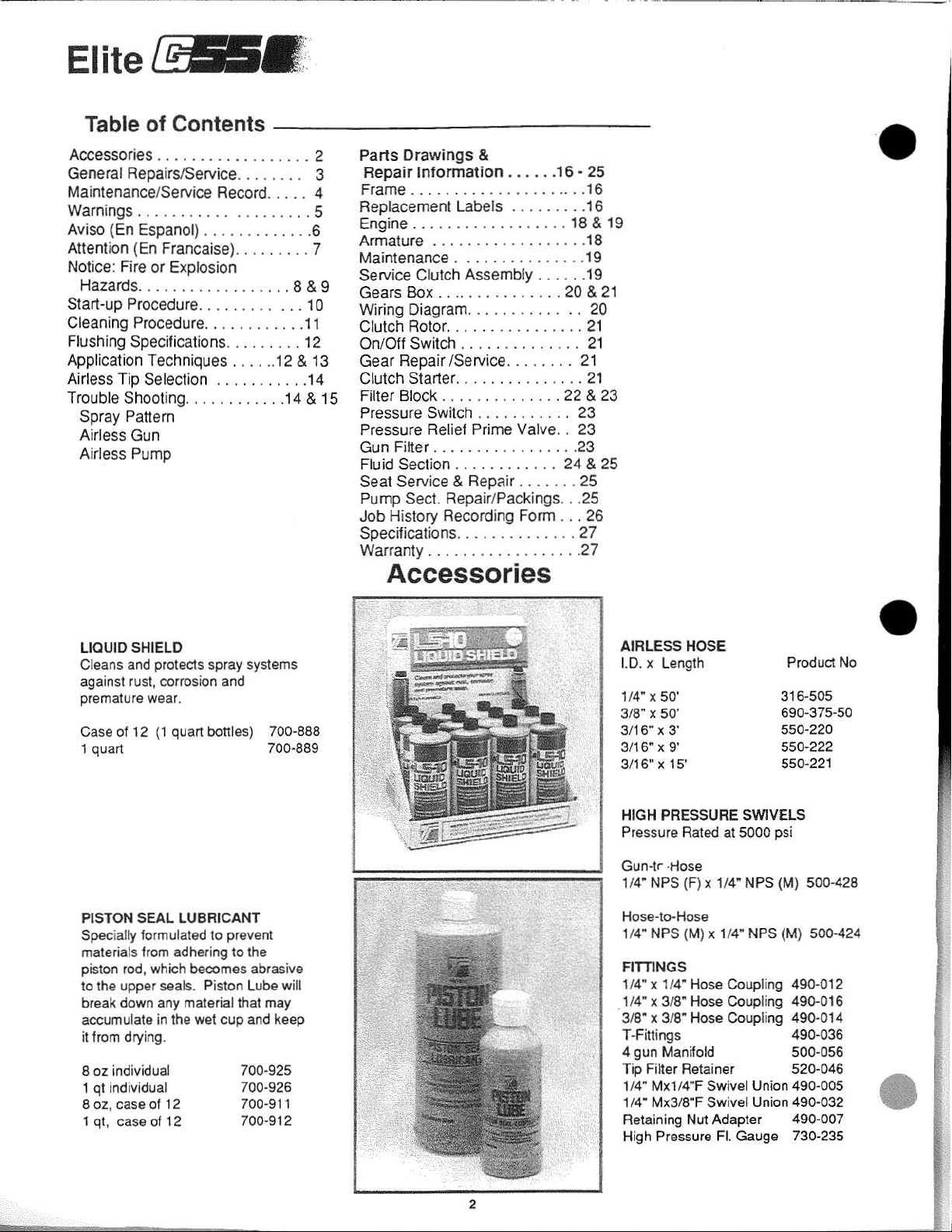
LIQUID SHIELD
Cleans
against
premature w
Case
Speci
to
and
protects spray systems
rust,
corrosi
on
and
ear.
of
12
(1
quart bottles) 700-888
1 quart 700-889
PISTON SEAL LUBRICANT
ally
formulated
materials
piston
break down
accumulate
it from
oz
8
1 qt individual
8
oz.
1 qt, case
from
rod
, which becomes abrasi
the
upper seals. Piston
drying.
individual
case
of
of
any
in
to prevent
adhering to the
material that
the wet
12
12
cup
700-925
700-926
700-9
700-912
Lube
may
and
ve
will
keep
11
AIRLESS HOSE
Prod
1.0. x
Length
1/4" x
so
·
3/
8"
X 50'
3/16" X 3'
3/16"
X 9'
3/16" X 15'
HIGH PRESSURE SWIVELS
Pressure
Gun-tr
1/4"
Hose
1/4"
FITilNGS
1/4" x 1/4"
.1/4" x 3/
3/8" x 3/
T-Fittings 490-036
4 gun Manifo
Tip Filter Retainer 520-046
1/
4"
1/4" Mx3/8"F Swivel Union 490.032
Retaining Nut Adapter 490-007
High Pressure
Rated
at
-
Hose
NPS
(F)
x 1/4" NPS
-to-Hose
NPS (M) x 1/4"
Hose
Coup
8"
Hose
Coupling 490.016
8"
Hose
Coupling
ld
Mx1
/4"F Swivel Uni
Fl.
5000 psi
NPS
lin
Gauge 730-235
uct
316-505
690-375-50
550-220
550-222
550-
221
(M}
500-428
(M)
500-424
g 490-012
490-014
500-056
on
490
-00
No
5
•
2
Page 3
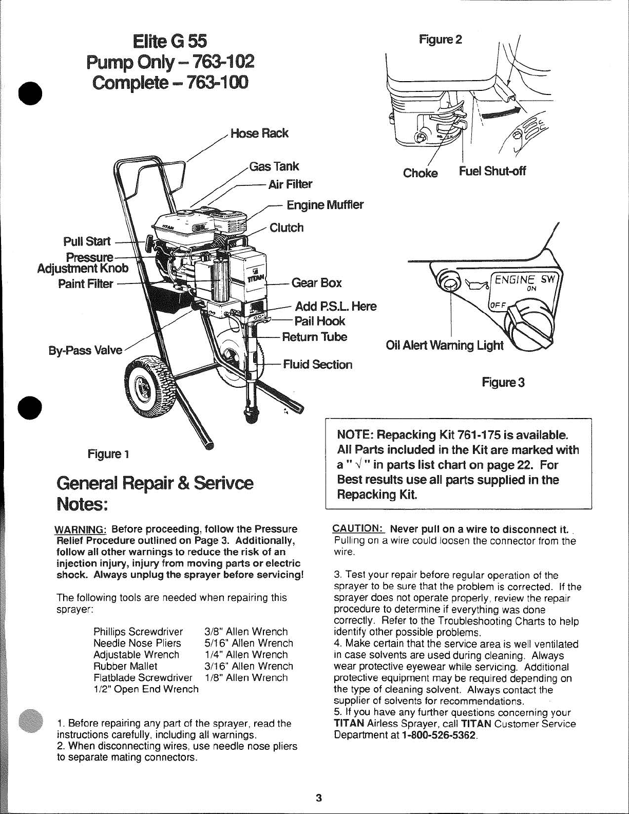
EliteG
55
Figure2
••
Adjustment Knob
Pump
Only-
Complete-
Pull Start
Pressure-~__,
Paint Filter
----l'll-IE
763-102
763-100
Hose
\tt'~~~b
Rack
--Pai
Add P.S.L Here
l
Hook
Choke
Fuel Shut-off
Oil Alert Warning Light
••
Figure
General
1
Repair & Serivce
Notes:
WARNING: Before proceeding,
Relief Procedure
follow
injection injury,
shock.
The following tools are needed when repairing this
sprayer:
1. Before repairing any part of the sprayer, read the
inst
2. When disconnecting wires, use needle nose pliers
to separate mating connectors.
all
other
Always
Phillips Screwdriver
Needle Nose Pliers
Adjustable Wrench
Rubber
Flatblade
1
/2" Open End Wrench
ru
ctions carefully, including all warnings.
outlined
warnings
injury
from
unplug
Mallet
the
Screwdriver
follow
on
Page 3. Additionally,
to
reduce
moving
sprayer
3/8" Allen Wrench
5/16" Allen Wrench
1/4" Allen Wrench
3/16" Allen Wrench
1
the
the
risk
parts
before
/8" Allen Wrench
Pressure
of
an
or
electric
servicing!
Figure3
NOTE: Repacking Kit 761-175
Parts included
All
a " v "
Best
in
parts
results
use
in
the
Kit
list
chart
on
all parts supplied in the
is
available.
are marked
page 22. For
with
Repacking Kit.
CAUTION : Never
Pulling on a wire could loosen the connector from the
wire.
3. Test your repair before regular operation of the
sprayer to be sure that the problem is corrected.
sprayer does not operate properly, review the repair
procedure to determine
correctly. Refer to the Troubleshooting Charts to help
identify other possible problems.
4. Make certain that the service area is
in
case solvents are used during cleaning. Always
w
ear
protective eyewear while servicing. Additional
protective equipment may be required depending on
the type of cleaning solvent. Always contact the
supplier of solvents for recommendations.
5.
If you have any further questions concerning your
TITAN Airless Sprayer, call TITAN Customer Service
Department at 1-800-52S.5362.
pull
on a wire
if
everything was done
to
disconnect
well ventilated
it.
If
the
.
3
Page 4
MODEL#
Titan
Tool
become
is
more
performance
The
chart
su
re
your unit is
Make
sure
Th
is i
nformation will
in
the
efficient
of
this
is
easy
always
to fill
SERIAL#
business
and
valuable
to
follow
running
in
the
boxes
be
needed
of
designing
profitable.
too
l to help
and
to
use.
at
peak
at
the top
to
validate
COMPANY
systems
the
maintenance
investment.
allows
for
We
feel
you
The
DATE
and
manufacturing
that
if
you
get
the
most
Maintenance
PURCHASED
spray
accurately
out
of
your
Schedule
track
performance.
of
this
record
with
the
model
number,
your
warranty
.
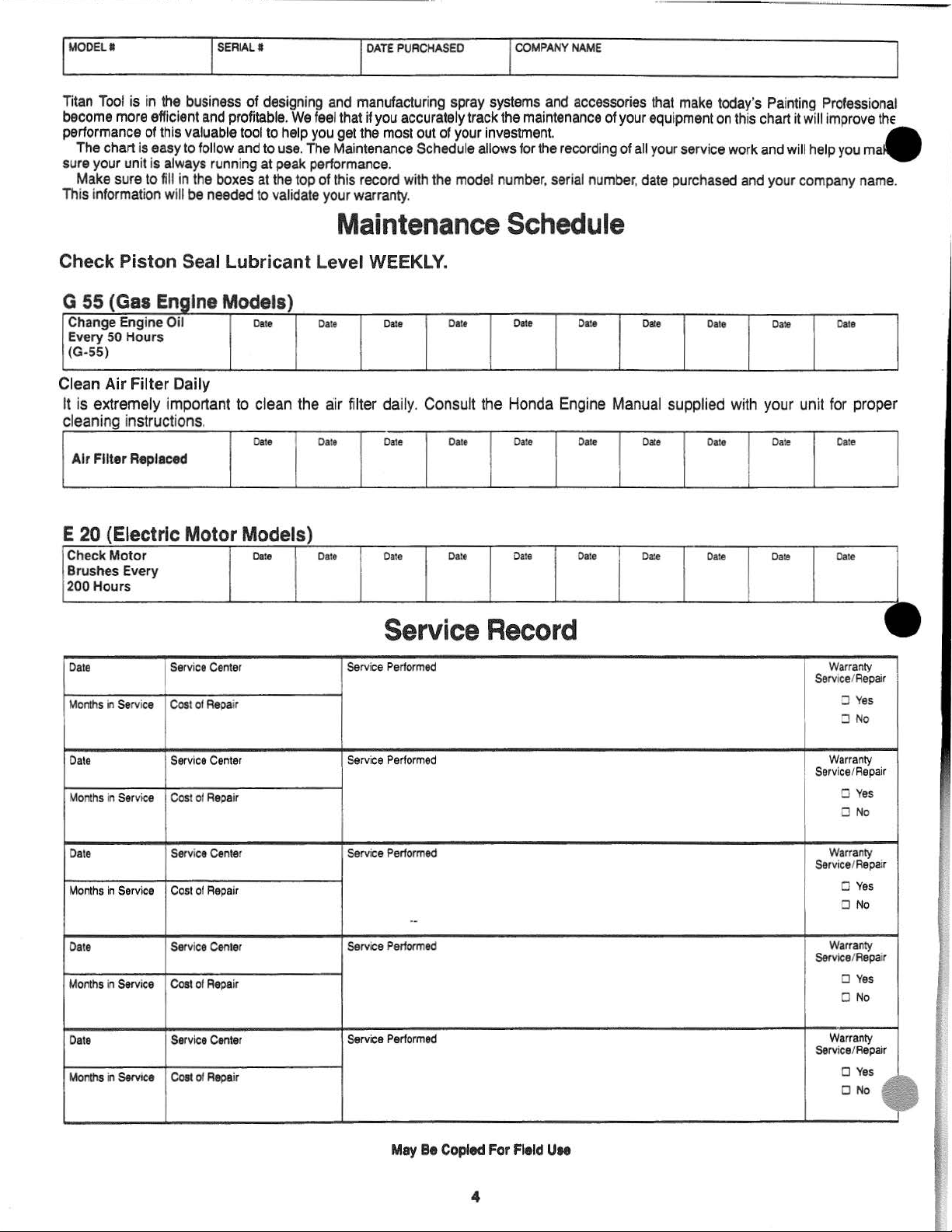
Maintenance Schedule
and
the
recording
serial
NAME
accessories
of
your
of
number, date
that
equipment
all
your
purchased
make
service
today
on
this
work
's
Painting Professional
chart
it
will
improve the
and
will help
and
your
company
you
•
ma
name.
Check Piston Seal Lubricant Level
G 55 (G
Change Engine Oil
Every 50 Hours
(G-55)
as
ng1ne
E
Mod I )
es
Date
Da
te
WEEKLY.
Date
Da
te
Clean Air Filter Daily
It
is
extremely important to clean the air filter daily. Consult the Honda
cleaning instructions.
Da
Air
Filter Replaced
te
Date
Da
te D
ate
E 20 Electric Motor Models
Check
Motor
Brushes Every
200 Hours
Date
ate
D
Da
te
Date
Service Record
Date
M
onth
s in Service
Service
Cost of
Center
Repai
Service
Performed
r
Date Date
Eng
ine Manual supplied with your unit for proper
D
Da
te
Da
te
ate
Date
Date
Da
Date
Da
te D
te
Date Da
Da
te
ate
te
Da
te
D
Dat
Da
Warran
Servtce/
0 Yes
ate
e
te
ty
Repair
0 No
Date
Months
Date
Months
Date
Months
Date
Months
in
Service
in Service
in
Service
in
Service
Service
Cost of
Serv
ice
Cost
of
Se
rvice
Cost
of
Service
Cost
of
Center
Repa
Center
Repair
Center
Repair
Center
Repa
Service
Performed
ir
Service
Performed
Service
Performed
Service
Perlormed
ir
May
Be
Copied
For
Field
Uee
War
ran
0
Yes
0 No
Warran
ice/
Repa
0
Yes
O
No
Warran
vicef
Repa
0
Yes
0
No
Warranty
ice/
Repair
D
Yes
O
No
ty
ty
ty
Service/Repai
Serv
Ser
Serv
r
ir
ir
~
~
4
Page 5
DO NOT USE EQUIPMENT BEFORE READING THIS SECTION
WARNING
HIGH PRESSURE SPRAY
CAN CAUSE SERIOUS INJURY.
Maximum Working Pressure 3000 psi, 210 BAR
An airless spray gun requires that fluid
spray
or
leak
s,
can penetrate the skin and inject substantial quantities of toxic fluid into the body. If not promptly
and properly treated, the injury can cause tissue death or gangrene and may result in serious, permanent
or
disability
airless spray equipment.
SIMPLE CUT!
NOTE TO PHYSICIAN: Injection into the skin is a serious, traumatic injury. It is important to treat the injury
surgically as soon as possible. Do not delay
coatings injected directly into the blood stream. Consultation with a plastic surgeon
surgeon may be advised.
1)
2)
3)
amputation of the wounded part. Therefore, extreme caution must be exercised when using any
IF YOU ARE INJECTED, SEE A PHYSICIAN IMMEDIATELY. DO NOT TREAT AS A
Handle the spray gun carefully. NEVER point the gun at yourself or anyone else. NEVER permit any part
of your body to come in contact with the fluid stream of either the gun or any hose leak.
gun trigger safety lever in a locked position when not spraying.
NEVER attempt to force the flow of fluid backward through the gun with your finger, hand
ject against the gun nozzle. This is
NEVER attempt to remove tip , disassemble
be
introduced to it at very high pres sure. Fluids under high pressure, from
trea
~men
t
to research toxicity. Toxicity is a concern with some exotic
or
a reconstructive hand
ALWAYS keep the
NOT
ALWAYS use a
AN
AIR SPRAY GUN.
or
repair equipment without first doing the following:
tip
safety guard .
or
hand-held ob-
•
•
PRESSURE RELEASE PROCEDURE
A.
Set trigger safety
B.
Shut off pump and unplug electrical cord.
C.
Release fluid pressure from entire system and trigger gun.
0.
Reset trigger safety
4)
Before flushing system, always remove spray tip and adjust fluid pressure to lowest possible setting.
5)
Tighten all fluid connections before each use. NEVER exceed 3000 psi with this unit. Make sure that all ac·
cessory hoses, connections, swivels and so forth can withstand the high pressures which develop. NEVER
exceed the pressure rating of any component
6)
WARNING: The paint hose can develop leaks from wear, kinking, abuse, etc. A leak is capable
fluid into the skin, therefore the paint hose should be inspected before each use.
hose with any part of your body, adhesive tape or any other makeshift device. Do not attempt to repair a
spray hose, instead replace it with a new grounded hose. Use only with hoses that have spring guards.
NEVER use less than 50' of hose with this unit.
7) Be sure that the airless equipment being used and the object being sprayed are properly grounded to pre-
vent static discharge
against metal container when flushing system with tip removed, to prevent static discharge.
8)
ALWAYS keep the working area around the pump well ventilated. Additionally, the pump itself should be a
minimum
explosion with certain materials. ALWAYS follow the coating
and warnings. Never spray flammable material near open flames, pilot lights
9)
ALWAYS wear spray masks and protective eyewear while spraying. Additional personal protective equip-
ment may be required depending on the type
Always contact supplier of material for recommendation.
1
0)
Keep all extension poles clear of electrical wires .
11)
NEVER alter or modify any part of this equipment; doing so could cause it
12)
NEVER leave equipment unattended. Keep away from children or anyone not familiar with the operation of
airless equipment.
of
25' from the spray area.
in
a locked position.
in
a locked position.
in
or
sparks which could cause fire
If
these instructions are not followed there is the possibility of fire
the system.
NEVER attempt to plug a
or
explosion. WARNING: ALWAYS hold the gun
or
solvent manufacturers safety precautions
or
any source of ignition.
of
material being sprayed and conditions
to
malfunction.
of
injecting
of
ventilation.
or
5
Page 6
NO USE EL EQUIPO ANTES DE LEER ESTA SECCION
AVISO
LA
ROCIADURA A PRESION
PUEDE
Presion de Trabaio Maxima 3000 Iibras por pulgado cuadrada (psi), 210 bar
Una pistol a rociadora sin aire requiere que se le introduzca fluido a presion muy alta. Los fluidos bajo presion alta,
Ia rociada
Sino
inhabilidad seria y permanente o en Ia amputacion
estrictas al usar cualquier equipo de rociadura sin aire.
MEDICO. ;NO TRATE
NOTA PARA EL MEDICO: La inyeccion en Ia piel es una herida seria y traumatica. Es importante tratar Ia herida
quirurgicamente
asunto importante en cuanto a
Puede que sea necesaria
de
ode
las fugas, pueden penetrar en Ia pie I e inyectar en el cuerpo cantidades considerables de fluido toxico.
se
atiende pronta y apropiadamente, Ia lesion puede causar muerte del tejido o gang rena, y puede resultar
LA
HERIDA COMO Sl FUERA UNA MERA CORTADURA!
lomas
Ia mano.
1) Maneje Ia pistola de rocio con cuidado. JAMAS apunte Ia pistol a hacia Ud. u otra persona. NUNCA permita
que parte alguna de su cuerpo se ponga en contacto con
manguera. SIEMPRE mantenga trabado el seguro de Ia pistola mientras no este rociando. SIEMPRE utilice
una virola de seguridad.
2) JAMAS intente forzar el flujo delliquido hacia atras por
contra Ia boquilla de Ia pistola, ya que esta no se trata de una PISTOLA DE ROCIO NEUMATICA.
3) JAMAS intente quitar Ia boquilla ni desarmar o reparar el equipo sin haber cumplido antes con los pasos
siguientes:
pronto posible. No demore el tratamiento para averiguar Ia toxicidad. La toxicidad es un
algunos revestimientos exoticos inyectados directamente en
Ia consultacion con un cirujano plastico o un cirujano especialista en
CAUSAR
de
Ia parte dariada. Por eso, hay que emplear precauciones
Sl USTED SE INYECTA. CONSULTE INMEDIATAMENTE AL
LESION
el chorro de liquido de Ia pistola
Ia
pistola con
ALTA
GRAVE.
el
dedo, Ia mano o
el
caudal sanguineo.
Ia
reconstruccion
ode
alguna fuga de Ia
un
objeto mantenido
ode
en
Ia
PROCEOIMIENTO DE DESCOMPRESION
A.
Coloque el seguro en posicion trabada.
B.
Apague Ia bomba y disconecte tambien Ia cuerda electrica.
C.
Descargue
D.
Vuelva a trabar el seguro.
4) Antes de enjuagar
posible.
5) Ajuste todas las conexiones antes de cada usa. JAMAS exceda 3000 Iibras por pulgada cuadrada con esta
unidad. Asegurese de que todas
accesorios
nominal
6) ADVERTENCIA: La manguera puede desarrollar fugas como resultado del desgaste, retorcimiento, abuso,
etc. Las fugas son capaces de inyectar
inspeccionada antes
adhesiva o cualquier otro expediente provisorio. Evite intentar reparar una manguera
reemplckela
re
7) Asegurarse
puestos a tierra para
CIA:
desprendida. para evitar descarga estatica.
8) SIEMPRE mantenga
ubicada a no menos de 25 pies de Ia operacion de rocio. Si
incendio o explosion con ciertos materiales. SIEMPRE obedezca las precauciones advertencias de los
fabricantes
flameante, encendedores mecheros o cualquier fuente
9) SIEMPRE use mascaras apropiadas y anteojos de proteccion durante Ia operacion
material usado y las condiciones
En todo caso obtenga las recomendaciones del fabricante del material.
1
O)
Mantenga todas las varas de extension fuera del alcance de cables electricos.
11) JAMAS altere o modifique parte alguna de este equipo, ya que ello puede causar deficiencias de funcionamiento.
12) JAMAS deje al equipo solo. Mantengalo fuera del a!cance
con
de
sorte. JAMAS use con esta unidad una manguera de menos de 50 pies.
Sostener SIEMPRE Ia pistola contra el receptacula de metal al inundar el sistema con Ia boquilla
Ia operacion de equipo no neumatico.
Ia
presion del liquido en todo el sistema y
el sistema, siempre quite Ia boquilla de rocio y ajuste Ia presion delliquido al valor mas bajo
las mangueras, conexiones, articulaciones
esten
en
condiciones de tolerar las attas presiones desarrolladas. JAMAS exceda Ia capacidad
cualquier componente del sistema.
l_iquido
de
cada uso. JAMAS intente obturar Ia manguera con una parte
c:;x>n
una manguera nueva conectada a tierra. Utilice solame nte mangueras con guardas de
que
el equipo sin aire que este empleando y el objeto que
evita~
descarga estatica o chispas que podrian poducir fuego o explosion. AOVERTEN-
ellugar
de
revestimientos y solventes. Nunca rocee material inflamable cerca a alga en llamas o
de
trabajo vecino a Ia bomba bien ventilado. Ademas, Ia bomba en
de
ventilacion puede ser necesario usar equipo personal protector adicional.
a traves de Ia piel, por lo que Ia manguera de pintura debe ser
Ia
pistola.
nose
obedecen estas insfrucciones hay riesgo de
de
encendimiento.
de
los nilios y
girato~ias
se
intenta rociar esten correctamente
de
cualquier persona no familiarizada
y demas elementos
de
su
cuerpo o con tela
de
rocio; en cambio
si
de
rocio. Segun el tipo
debe estar
de
6
Page 7
••
NE
PAS UTILISER LE MATERIEL AVANT D'AVOIR LU
CETTE
SECTION
ATTENTION!
LES
PEUVENT
Le liquide introduit dans un pistole! pulverisateur sans air
haute pression ,
d'injecter d'importantes quantites
toute
I'
attention voulue, une blessure causee
lieu a
de
done lors
IMMEDIATEMENT. NE TRAITEZ PAS
REMARQUE A L'INTENTION DU MEDECIN : Une injection penetrant Ia peau constitue une lesion traumatique grave
qu
'il est important
de
!'injection.
revetements exotiques. La consultati
Ia main peut etre recommandable.
1) Maniez
personne.
du
lorsque vous n'etes pas occupe a
pistolet.
2) N'essayez jamais d'enlever Ia buse,
suivante:
en
serieux handicaps permanents, voire a !'amputation du membre atteint. Une prudence extreme s'
de
!'utilisation de materiel
II
s'agit Ia d'un risque a
le
pistolet avec soin. N'en dirigez
Ne
pistolet
ou
PULVERISATEURS A HAUTI;
PROVOQUER
Pression de travail maximale: 3 000
provenance du pu lverisateur
de
liquide toxique
de
Ia sorte peut provoquer Ia necrose
de
pulverisation sans air. EN CAS D'INJECTION, CONSULTEZ
LA
BLESSURE COMME S'IL S'AGISSAIT D'UNE
de
trailer chirurgicalement aussit6t
en
visager en cas d'injection directe dans le circuit sanguin
on
d'un chirurgien plasticien ou d'un specialiste de Ia chirurgie reconstructive
jama
laissez jamais aucune partie
d'une fuite quelconque au niveau du tuyau. Verrouillez toujours
pulve
riser. Veillez a toujours utiliser un dispositif
de
demonter ou
DE
SERIEUSES.LESIONS
do
it l'etre a pression extremement elevee. Les liquides a
ou
d'une fuite quelconque,
dans
l'organisme. Si elle
que
possible. Ne perdez pas
is Ia
buse
vers aucune partie de votre corps ou vers aucune autre
de
votre corps entrer
de
reparer l'appareil avant d'avoir accompli Ia procedure
psi-
en
contact avec
PRESSIO
210
sont
capables de penetrer Ia peau
n'est
pas
des
de
temps a rechercher Ia toxicite
le
.N ...
bar
traitee promptement et avec
tissus ou gangrene et
le
flux
levier
SIMPLE
de
de
de
COUPURE!
liquide s'
surete
surete a Ia buse
UN
MEDECIN
de
echappant
de
Ia
et
donner
impose
certains
de
detente
du
•
PROCEDURE DE RELACHEMENT DE PRESSION
A. Verrouillez Ia surete
B. Eteignez Ia pompe
C. Relachez Ia pressi
D.
Re·verrouillez Ia surete
de
3) Avant
niveau
4) N'utilisez aucune
5) N'essayez
objet maintenu contre Ia buse du pistolet.
AIR.
6) ATTENTION: Des fuites risquen t
torsions,
peau
N'essayez jamais d'obturer une fuite
adhes
remplacez-le plut6t par un nouveau tuyau mis
de
Serrez
7)
cet
etc. sont bien capables de resister aux hautes pressi
nominale d'aucun composant du systeme.
8) Assurez-vous
a eviter
explosion. Tenez toujours
Ia buse.
d'aucune source d'allumage.
9) Le moteur electrique
bonne
pompe
presentent,
precautions et avertissements du fabricant de chaque solvant ou revetement utilise.
Portez toujours un masque et
1 0)
de
d'aeration. Demandez toujours
11) Maintenez toutes les tiges
12)
Ne
inexperimentee quant a l'usage
proceder au
le plus faible possible.
jama
is de refoul
des
rudes traitements, etc. auxquels il
sont
possibles par Ia voie de telles fuites.
if
ou
de tout autre moyen
securite a ressort.
bien
tous les raccords du systeme hydrodynamique avant chaque emploi. Ne depassez jamais,
appareil,
une
pression
que
toute
decharge d'electricite statique ou toute etincelle susceptible
Ne
jamais
ventilation
a une distance minimale
a defaut
protection personnelle peuvent etre necessaires suivant
laissez jamais le materiel sans surveillance. Gardez-le hors
de
Ia detente.
et
debranchez le cordon electrique.
on
dans !'ensemb
de
Ia detente .
rin~age
piece de materiel sans air avec
du systeme, enlevez toujours Ia buse
er
le flux
de
le du systeme et appuyez sur Ia detente du pistolet.
de
liquide dans
CET
de
se
produire le long du tuyau
II
a
I'
aide
de
fortune. N'essayez pas non pl
a Ia t
de
3 000 psi. Assurez-vous que
le materiel sans air utilise et
le
pistolet contre
vaporiser
de
de
Ia
de
cet
zone
suivre
de
substances inflammables a proximite de
appareil n'
de
des
de
est
travail et
de
ces
consignes, un risque d'incendie ou d'explosion. Suivez toujours
lunettes
ses
recommandations a votre fournisseur.
rallonge a distance
de
materiel sans air.
que
un
recipient en
pas protege contre les explosions.
des
alent
25
pieds (7,5 m) de Ia zone
de
protecti
de
pulverisation et reglez Ia pression au
une
pompe non equipee d'une soupape
le
pistole! au moyen
APPAREIL N'
est
eventuellement soumis. Les injections
est done important d'inspecter le tuyau avant
votre doigt ou
erre.
ons
I' objet a peindre sont adequatement
ours
de
on
des
EST
de
Veillez a n'
tousles
prevues. Ne depassez jamais Ia capacite
metallors
Ia pompe.
lors
de
vos travaux
le
type
fils electriques .
de
de
votre doigt,
PAS UN PISTOLET PULVERISATEUR A
de
peinture sous l'effet
tout autre membre
us
de reparer un tuyau
ut
iliser
que les
tuyaux accessoires, raccords, articulations,
de
du
rin~age
flammes
II
II
est
egalement important
de
pulverisation.
de
de
produit pulverise
portae
des
de
surpression.
de
votre main ou
de
l'usure,
de
liquide
chaque
de
votre corps,
de
tuyaux munis
mis
a Ia terre,
provoquer un incendie ou
du
systeme, apres en avoir
nues, lampes temoin
est
done essentiel d'assurer
Certains
pulverisation. D'autres articles
et
entants
et
de
toute personne
dans
usage
de
ruban
pulverisation ;
de
dispositifs
avec
de
pression
de
fa~on
de
maintenir Ia
materiaux
les conditions
d'un
des
Ia
.
une
ote
ni
une
les
7
Page 8
FIRE OR EXPLOSION HAZARD
Static electricity is created by the high velocity of fluid through the pump, hose and tip. If every part of the spray
element
also occur when plugging in or unplugging a power supply cord, or starting a gas engine. Sparks can ignite
fumes from solvents or the fluids being sprayed. Always plug the sprayer into an outlet at least
spray area. WARNING: Always flush
the
discharge
If
Check the entire system for proper grounding.
ELECTRIC MOTOR
Although tota
keep the working
from the spray
the pump with any flammable so lvents, while the pump is plugged in or operating.
GAS ENGINE (Where Applicable)
Always keep
solvents away
on a hot
grounded object, i.e. water pipe. NOTE: Refer
Information.
FLUID SECTION
. Halogenated Hydrocarbon solvents can cause an explosion when used with aluminum or galvinized components
in a closed (pressurizable) fluid system (pumps, heaters, filters, valves, spray guns, tanks, etc.)
The explosion could cause serious injury, death, and/or substantial property damage.
Cleaning agents, coatings, paints, etc., may contain Halogenated Hydrocarbon solvents.
Titan
Halogenated Hydrocarbon solvents.
is
not properly grounded , sparking may occur and the system may become hazardous. Sparking may
25'
away from the •
the
unit
Into a separate metal container
gun held
you
experience any static sparking or slight shock while using this equipment stop spraying immediately.
Tool
firmly
which
lly
area.
pump
from
surface can
Inc. spray equipment includes aluminum or galvinized components and will
against
could cause
enclosed, the electric motors used by
area
around the pump well ventilated.Additionall
WARNING:
outside
engine exhaust. (Never
ignite
the
side
of
the
container
serious
Always keep pump outside
of
any enclosed spray area. Keep area around
and cause a fire.) Always attach ground
bodily
fill
injury.
Do
not use the system again until the problem has been corrected.
the
to
engine
TIT
fuel
to
assure
AN
are not explosion proof. Therefore,
of
any enclosed spray
tank
while
owners
proper
y,
the pump itsel f should be a minimum of
the
manual
pump
engine
wire
for
with
the
spray
tip
grounding
area.
is
running
located
additional
and prevent static
Never clean the exterior
well
ventillated. Keep
or
hot
on
rear
safety
removed
it
is
essential
. Fuel
of
engine
and service
be
affected by
and
to
25'
of
all
spilled
to
a
EXPLANATION OF THE HAZARD
There are three key elements to the Halogenated Hydrocarbon (HHC) solvent hazard. These elements are:
1. The presence
2.
Aluminum
3. Equipment Capable
When all three elements are present, the result can be an extremely violent explosion. The reaction can
tained with very little aluminum or galvanized metal: any amount of aluminum is too much.
Th
e reaction is unpredictable. Prior use of an HHC solvent without incident (corrosion or explosion) does NOT
mean that such use is safe.
La alta velocidad delliquido dentro de
equipo de rocio no esta conectado a tierra correctamente pueden producirse chi spas y el sistema se vuel
Tambilm pueden producirse chispas al enchufar o desenchufar cables electricos o al poner
molor. Las chispas pueden encender los
conecte el rociador a
ocurren chispas de electricidad estatica o si sufre
immediate. Verifique que el sistema en su totalidad este conectado a tierra correctamente. No vuelva a usar el
sistema hasta que el problema haya side resuelto.ADVERTENCIA: Lavar siempre Ia unidad
un
recipiente metalico separado con Ia
lado
del recipiente para asegurar
lesi6n
MOTOR ELECTRICO:
Los motores electricos utilizados
area de trabajo alrededor de
minima de 25 pies (7,5 m) del
ar
este conectada o operando.
corporal grave.
ea
de rociadura cerrada. Nunca limpie el exter
of
HHC solvents.
or
Galvanized Parts .
of
Withstanding Pressure.
PELIGRO
un
enchufe ubicado a no menos de 25 pies de distancia del rociador y Ia zona de rocio.
Ia
area
DE
Ia
bombay
una
por
TITAN no son a prueba de explosion. Por lo tanto,
bomba bien ventilada. Ademas,
de rociadura.ADVERTENCIA: Mantener siempre
INCENDIO 0 EXPLOSION
Ia
manguera produce electricidad estatica.
vapor~
_s
provenientes de los solventes o de
un
cheque ligero mientras usa el equipo, deje de rociar de
boca
del rociador removida y teniendo Ia
puesta a tierra correcta y evitar Ia descarga estatica
Ia
bomba misma debe estar a una distancia
ior
de
Ia
bomba con solventes inflamables mientras Ia bomba
Si
algun componente del
ve
peligroso.
en
funcionamiento el
los
liquidos rociados. Siempre
por
inundacion
pistola
firmemente contra el
que
pod
ria causar
es
esencial mantener el
Ia
bomba fuera de cualquier
be
sus-
en
•
Si
l
e l
8
I
Page 9
•
MOTOR A
Siempre
bien
cuando
encenderse y producir
debe
manual
SOLVENTES
Los solventes a base de hidrocarburos halogenados pueden provocar explosion cuando se usan con componentes
galvanizados
pistolas de rocio, tanques, etc.)
La explosion podria causar lesiones serias e inclusive
Los
halogenados.
El equipo
solventes a base
GASOLINA:
mantenga
ventilada
el
motor
estar
siempre
de
uso
liquidos
de
{Where
Ia
bomba
. Mantega
este
del
ode
de
limpieza, revestimientos,
rocio ofrecido por Titan tiene componentes galvanizados o
de
todos
funcionando o caliente.
un
conectado a un
motor
aluminio en un sistema liquido cerrado (sujeto a presion) (bombas, calefactores, filtros, valvulas,
hidrocarburos halogenados.
Applicable)
fuera
los
solventes
incendio.
para
informacion
de
cualquier
El
alambre
objeto
lejos
El
combustible
que
adicional
pinturas
zona
de
roci
o cerrada.
del
escape
de
tierra
este
Ia muerte, asi como daflos materiales de consideracion.
, etc. pueden
del
derramado
que
esta
haciendo
sobre
seguridad y mantenimiento
motor.
tierra,
contener
Mantenga
Nunca
sobre
localizado
por
solventes a base de hidrocarburos
de
aluminio y es afectado
Ia
Ilene
el
una
super1icie
en
Ia
parte
ejemplo,
zona
tanque
calier
vecina
de
combustible
caliente
de
atras
ia. NOTA: Vea
.
por
a Ia
del
bomba
puede
motor,
el
.
•
EXPLICACION
Hay
tres elementos fundamentales que condicionan el riesgo
1.
Presencia
2.
Componentes
3.
Equipo
Cuando todos estos elementos estan presentes, el resultado puede ser una explosion sumamente violenta . La
reaccion puede tener
cantidad
La
reaccion
anteriormente sin accidentes (corrosion o explosion)
DANGER!
La vitesse du liquide a travers Ia pompe et le tuyau pr.oduit
pulverisation ne sont pas mis
rendre
d'un cordon de raccordement electrique
susceptibles d'enflammer les vapeurs des solvants ou les liqu ides
pulverisateur dans une prise situee a au moins 25 pieds (7,5 m) du pulverisateur et
Si vous remarquez
Iegere decharge electrique en cours d'utilisation du materiel, arretez immediatement Ia pulverisation. Assurez-vous
que
le
MOTEUR
MOTEUR AU
N'introduisez
pompe
moteur
une
fil
Pour
moteur.
SECTION HYDRODYNAMIQUE
Les solvants a hydrocarbure halogene sont explosifs en presence de pieces
systeme hydrodynamique
reservoirs,
L'explosion provoquee pourrait donner lieu a des lesions corporelles graves ou meme mortelles et/ou a
degats materiels.
le systeme dangereux. Des etincelles peuvent egalement se produire los de branchement ou debranchement
tousles
probleme.
Les
moteurs
d'assurer
maintenir
N'introduisez
a I' aide
de
soient
. (Ne
sur1ace chaude,
de
terre
plus
DEL
RIESGO
de
solventes
galvanizados o de
capaz
de
aluminio es excesiva.
no
de
tolerar
Iugar aun cuando Ia cantidad de aluminio o metal galvanizado sea muy pequefla : cualquier
puede predecirse. El hecho
RISQUE
Ia
formation d'etincelles sous l'effet de Ia presence d'electricite statique ou que vous ressentez une
elements du systeme
ELECTRIQUE
electriques
une
bonne
Ia pompe a
jamais Ia
solvants
GAZ
jamais
toujou
remplissez
situe a l'arriere
de
details
etc
.)
utilises
ventilation
une
distance
pompe
inflammables
(Where
sur
Applicable)
Ia
pompe
rs
bien
jamais
le
gaz
pourrait
du
les
mesures
ferme (pressur-isable) (pompes, radiateurs, filtres, soupapes, pistolets pulverisateurs,
de
hid
rocarburos
presion.
aluminio
de
que un solvente a base
halogenados.
.
NO
significa de que dicho uso
D'INCENDIE
de
a Ia terre de maniere adequate,
ou
lors
de
Ia mise en marche d'un moteur
sont
bien mis a Ia terre. Ne remettez pas le systeme en marche avant d'avoir resolu
par
TIT AN ne
de
Ia
zone
minimale
dans
une zone
pendant
dans
une
aeres.
le
moteur a un
Ne
reservoir a carburant
s'enflammer
de
securite
de
travail
de
que
Ia
zone
placez
objet
sont
pas
et
des
de
25
pieds
pulverisation
pompe
de
aucun
et
mis
et
est
pulverisation
solvant a proximite
lorsque
provoquer
a Ia
terre
d'entretien
de
los Hidrocarburos Halogenados, a saber:
de
hidrocarburos halogenados haya sido usado
noes
peligroso.
OU
l'electricite statique.
il
s risquent de favoriser Ia production d'etincelles et de
pulverises. Veillez done toujours a brancher le
proteges
environs
(7,5
branchee
contre
m)
fermee. Ne
fermee. Veillez a
le
moteur
un incendie
(par
exemple,
pertinentes,
D'EXPLOSION
Si
tousles elements du materiel de
au
gaz. De telles etincelles sont
de
Ia zone de travail.
les
explosions. II
de
Ia
pompe
de
Ia
jamais
ou
en
tourne o s'il
. II
est
egalement
zone
de pulverisation. ATTENTION:
nett
oyer
l'exterieur
marche.
ce
que
du
systeme
.) Veillez a
une
conduite
consultez
ga
tvanisees ou en aluminum dans un
d'echappement
est
chaud. Renverse
toujours
d'eau)
le
manuel
est
done essen tiel
important
de
les
environs
bien
attacher
. REMARQUE:
fourni
de
Ia
pompe
avec
serieux
de
du
sur
de
Ia
le
le
9
Page 10

Certains produits d'entretien, revetement
halogene.
Le
s appareils pulverisateurs de Ia Titan com portent des pieces
sensibles aux solvants
EXPLICATION
Le danger que presentent les solvants a hydrocarbure halogene se caracte
1.
Ia presence
2. Ia presence
3.
un
La
comb inaison de ces trois elements peut donner lieu a une explosion extremement
produire
en constitue
La
aucun incident (corrosion ou explosion) NE CONSTITUE NULLEMENT
en
reaction est imprevisibl
DU RISQUE
mate riel capable
presence d'une quantile minime d'aluminium ou de metal galvanise.
deja trop.
a hydrocarbure halogene.
de
solvants
de
pieces
a h
en
alu
de
supporter des pre
e.
Toute
s.
peintures et autres l
ydrocarbure
minium
utilisation anterieure de solvant a hydrocarbure halogene n'ayant donne lieu a
halogene,
ou
galvanisees,
ssions
iq
uides contiennent des solvants a hydrocarbure
en
aluminium et des composants galvanises
ri
se
par trois elements
elevees.
vi
olente. La reaction peut se
En fait,
un
signe de securite.
Ia
moindre trace d'aluminium
ch~s:
HALOGENATED SOLVENTS SOLVENTES HALOGENADOS SOLVANTS HALOGENES
DEFINIT
DEFIN
DEFINITIONFl
ION-Any hydrocarb
ICION-Cu
uorine (
F)
"-fluor-" Chlorine (CI) "-chlor
alquler sol
Tout
solvant a
on
solvent
vente
a base
hydrocarbure
containing
de
hidrocarburos
contenant
o-"
Bromine (Br) "-bromo
any
of
the
following
que contenga cualqulera de
l'un
des
elements
elements:
sulvants
-"
Iodine (I) "-lodo
estos
elementos:
:
-"
•
EXAMPLES
FLUOROCARBON SOLVENTS:
Dichloroflouromethane
T richloroflou
BROMINATED SOLVENTS:
Eth
ylene dibromide
Methylene chlo
Methyl bromine
Consult y
bon Solvents.
Consulte
im
revest
Pour determiner si vos
sultez votre fournisseur.
(not
all-inclusive):
ro
m ethane
ro
bromide
ou
r material suppli
Ia
informacion suministrada
iento contiene Hidrocarburos Halogenados.
er
to determine whether your solvent or coating contains Halogenat
solvants ou revetements contiennent des solvents a hydrocarbures ha log enes, con-
EJEMPLOS
IODINATED SOLVENTS:
N-butyl iodide
Methyl iodide
Ethyl iodide
Propyl iodide
CHLORINATED SOLVENTS:
Carbon tetrachloride
Chloroform
Ethylene dichloride
por
su proveedor de materiales para determinar si un solvente o
(lista
parcial):
EXEMPLES
METHYLENE CHLORIDE
DICHLOROMETHANE
Monochlorobenzene
Orthodichlorobenzene
Perchloroethylene
TRICHLOROETHANE
Trichlorothyle
Monochlorotoluene
(llste Incomplete):
START UP PROCEDURE
WARNING: High pressure device, thoroughly read and understand the warning section located
manual and the label on the sprayer.
IMPORTANT: Whenever starting
is
never operate th
ings.
Do not operate
sprayer for more than
dry
.
or
cleaning this sprayer always reduce engine or motor speed. Additionally,
10
seconds without fluid, this can cause unnecessary wear to the pack-
ne
ed
Hydrocar-
in
the owner's
or
•
Step
1:
Before you plug in the power cord
A. Tighten suction and return hoses, then ins
airless gun. Do not install tip yet, or remove if installed.
hoses and spray gun, be sure t
pr
working
caused by static sparking and fluid injection
B. Preset pressure control
C. Place on-off switch in the off position .
D. Be sure
essure, and that the gun has a tip guard. This is to reduce the risk of serious bodily injury
to
fill
the Wet Cup 1/3 full with Piston Seal Lubricant.
he
by
turning the pressure control knob counterclockwise to lowest setting.
to
the electrical outlet or start the gas engine, do the following.
ta
ll a minimum of
y are electricall y grounded and rated for at least 3000 psi (210 bar)
or
overpressurization, causing a component rupture.
SO'
of nylon airless spray hose and
WARNING: If you are supplying your own
10
Page 11

Step
Step
•
Step 4: Flush oil out of new paint pump: Oil is used by the factory for testing and protection. It is necessary to
Step
•
Step
Step
Step
Step 9: Check for leaks. If any leaks occur, follow the proper pressure
Step 10: Turn off sprayer and relieve pressure by turning pressure relief prime knob to prime.
~I
Step 11: With gun trigger lock engaged, install tip and guard as instructed
Step 12: Turn sprayer on and rotate the pressure relief prime valve to the spray position.
Step 13: Test on cardboard to check spray pattern. Adjust pressure just until the spray from gun is completely
2:
ELECTRIC MOTOR
A.
Check electrical service, be sure it
B.
Plug electrical cord into a grounded outlet that
all
extension
remove
3:
GAS ENGI
A.
Check
tions.
B. Fill
cause a fire. Close the black fuel shut off lever located under the air cleaner.
Use unleaded
C.
If a secondary hose and gun is not installed be sure the plug is secure.
D.
Place the suction tube into container containing mineral spirits.
E.
Open ttie fuel shut off lever by pushing it
F. Move the throttle lever away from fuel tank.
G.
Close the engine choke lever, located beneath the air cleaner.
H. Turn the engine switch on. Turn pressure relief prime valve down to prime
position.
I.
Pull the starter rope, holding the frame wi
and firmly. Continue to hold the rope as you let it return. Pull and return rope
until engine starts.
flush out with mineral spirits before you begin to spray.
A. Pour
B. Turn pressure relief prime valve down to prime position and turn unit on. Increase pressure slightly.
Let solvent cycle for approximately 30 seconds. Then tilt syphon tube above container and let the
sprayer pump itself dry. Then turn unit off. If you are going to use water based paints, repeat procedure using water.
5:
Prepare the paint according to manufacturer's recommendations. Remove any skin that may have
formed and stir. Strain the paint through a fine nylon mesh bag to remove particles that could clog
spray tip.
6:
Place syphon and return tubes into paint container. Turn pressure relief priming knob, located on side
of
pump, down for priming.
7:
Turn sprayer on and turn up pressure slightly. Let circulate on prime until no bubbles filter up through
the paint.
8:
Hold gun firmly against a metal container, disengage trigger lock and trigger gun against side of container. Then, while gun is triggered, turn the pressure relief val
triggered until all the air is forced out of the system and the paint flows freely. Release the trigger and
engage gun safety lock, set gun down while unit pressurizes.
atomized.
the
the
112
cords
are a
three wir
thi
rd
prong
NE
(Where
engine
gas
tank
gallon mineral spirits into a metal container and insert syphon and return tube.
or
use
an adaptor. Never exceed 150' of extension cord.
Applicable
oil
level. Refer to the engine manual supplied, for instruc-
. Be sure the engine is cool, refueling a hot engine could
high
qualit
y gasoline.
is
120V 15 amp minimum and that outlet is properly grounded.
is
at
least 25' from the spray
e, 12 gauge minimum cord
)
in
the direction of t
th
one hand, pull the rope rapidly
with
he
arro
ve
to the spray position. Keep the gun
rel
ief procedure before tightening.
in
separate tip or gun manual.
are~.
a grounded
w.
Make certain that
Remove T
plug
ip
and
when flushi
. Never
/
Safe
ty Guard
ng
CLEANING
WARNING: High pressure device, follow all safety warnings located on sprayer and in the owner's manual.
Always
away from t
Step
Step 2: Turn off pump and release fluid pressure, by turning the pressure relief prime valve located on the side
Step 3: Remove tip and let soak clean, in a small container of solvents
cle
an u
sing
low
pressure,
he sprayer . Never clean
1:
Engage trigger safety lock on gun.
of pump down.
possible setting.
with
the
the spr
exterior
PROCEDURE
ay
tip
removed. Always flush
of
the
pump
11
while
into
a separate metal
the
pump
or
water. Adjust fluid pressure to lowest
is
plugged
----
container
in
or operating.
---~~~---------
-
----~--~-----~------------
-
Page 12

Step 4:
Step
Step
Step
Step
Step 9: Turn prime valve down and remove suction tube from cleaning container, turn unit on and allow sprayer
Step 10: Take a clean container of water
Step 11: Take suction tube out of container and let sprayer run itself dry.
Step 12: Check filter on pump and gun. Clean
Step
Tum
the pump on. Tilt syphon tube above paint container allowing the sprayer
through the return tube. I
5:
Have container
clean with mineral spirits
not
6: Place syphon tube into container with hot soapy water
turn unit off.
7:
To save paint still in spray hose, turn prime valve up
against side. of
gun and
8:
Trigger gun and let cleaning solution circulate for approx. 2-3 minutes, then turn unit off.
to
pump dry.
cleaning
will protect against corrosion.
13:
Remove spray tip from solvent, clean with a soft bristle brush and store
of
hot soapy water if spraying latex (or suitable solvent for oil base paints,) available. Do
if
using latex paint, this will make jelly.
or
solvents. Let circulate for 2-3 minutes, then
to
spray position, then carefully trigger gun into and
metal paint container. Be careful of splashing. When cleaning solution appears, shut off
place
gun
in a separate metal container. Repeat process if spraying with two guns.
or
solvent and using low pressure pump through system until clear. If
with water , pump a small amount of mineral spirits
or
replace.
or
Til
LS-10 solution through pump. This
in
a dry place.
to
pump itself
dry~
FLUSHING SPECIFICATIONS
1. New Sprayer: Oil is used by the factory for tes
A.
If spraying water-base paint, flush with mineral spirits followed by water.
B.
If spraying oil-base paint, flush with mineral spirits only.
2. Changing from water-base
3.
Changing from oil-base
4.
Changing colors: Flush with a compatible solvent such as water
5.
Storage: To asure proper performance and long life, always clean the sprayer thoroughly before storing .
A.
Water-Base Paint: Flush with water, then mineral spirits and leave the pump, gun and hose filled with
mineral spirits. Shut-off and unplug the sprayer and turn pressure relief prime valve
pressure. Return prime valve to spray position.
B.
Oil-Base Paint: Flush with mineral spirits. Shut-off and unplug the sprayer, turn the pressure relief prime
valve
to
prime to relieve pressure and leave open. Return prime valve to spray position.
6. Start-Up After Storage:
A.
Water-Base Paint: Flush out mineral spirits with wate
B.
Oil-Base Paint: Flush out the mineral spirits with the material to be sprayed.
Always dispose of mineral spirits in a proper way.
to
oil-base: Flush with water then mineral spirits.
to
water-base: Flush with mineral spirits then water.
ting and
protection. It is necessary
or
mineral spirits.
r.
to
flush unit before spraying.
to
prime to relieve
APPLICATION TECHNIQUES
The following techniques, if followed, will assure professional painting results.
Hold the gun perpendicular
equal distance from the surface. Depending on the type
of
material, surface or desired spray pattern, the gun
should be held at a distance of
Move the gun either across
dy
a stea
serves material and provides even coverage. The correct
spraying speed
without runs
Holding the gun closer to the surface deposits more paint
on the surface and produces a narrower spray
Holding
ner coat and wider spray pattern . If runs, sags
cessive paint occur, change to a spray tip with a smaller
orifice. Conversely, if there
paint on the surface or you desire to spray faster, a
orifice tip should be selected.
rate. Moving the gun at a constant speed con-
allows a full wet coat of paint to be applied
or
sags.
the gun farther from the surface produces a thin-
to
the surface and always at
12
to
14 inches.
or
up
and down the surface at
is
an insufficient amount of
pattern.
or
ex-
larger
PROPER TECHNIQUE
start pull
stroke trigger
Maintain uniform spray stroke action. Spray alter-
from left to right and right to left. Begin move-
nately
ment of the gun before the trigger is pulled.
release end
trigger stroke
•
12
Page 13

Proper lapp ing (overlap of spray pattern) is essential to
each
stroke.
horizontally, aim at the bottom edge of
the
preceeding stroke,
previous pattern by
an
even finish. Lap
If
you
are
so
50%
spraying
as
to
.
lap
the
OVERLAP EDGES
•
WRONG TECHNIQUE
'
Avoid arcing or holding the gun at
result in an uneven finish .
~
Too Thick
ARCING GUN AT ANGLE
Off
spray
an
angle. This will
1
i
1s
PASS PASS PASS PASS PASS
2nd
t
1
3rd
4th
5th
•
or
corners and edges, split the center of the spray pat-
F
tern on the corner
bo
th adjoining
amounts of paint.
If conditions are windy, angle the spray pattern into the
wind
to
minimize drifting. Work from ground
not attempt to spray if wind is excessive.
When spraying with a shield, hold it firmly against
toward the surface. This will prevent pai
Shrubs next to houses should be tied back and covered with a canvas cloth. The cloth should be removed as soon as
possible. Titan Gun Extensions are extremely helpful
Nearby objects such as automobiles, outdoor furniture, etc.,
of
a spray job. Be careful of any other surrounding ohjects that could
or
edge and spray vertically
sections
receive
so
that
approximate
nt
from being forced underneath.
even
to
roof. Do
the
surface. Ang le
in
these situations.
should
the
be
spr
ay gun
moved
be
damag
slightly away from the shield
or
covered whenever in
ed
by
overspray.
the
and
vicinity
13
Page 14

AIRLESS TIP SELECTION
Tips are selected
specific job and by the orifice size that
For light viscosity fluids, smaller orifice tips generally are desired. For heavier viscosity materials larger orifice tips
are preferred. Please refer to the chart below.
Note:
Do
not exceed the pump 's recommended tip size.
The following chart indicates the most common sizes and the appropriate materials to be sprayed.
Fan
widths measuring
likely to plug.
by
the orifice size and fan width. The proper selection is determined by the fan width required for a
.
011
.0
15-
.021
- .013
.019
- .026
will supply the desired amount
Lacquers & Stains
Oil & Latex
Heavy Bodied Latex and Blockfillers
8"
to 12" are most preferred because they offer more control while spraying and are less
of
fluid and accomplish proper atomization.
00 Mesh Filter
1
60
30 Mesh Filter
Mesh Filter
TROUBLESHOOTING SPRAY PATTERNS
PROBLEM
Tails
PROBABLE CAUSE
1. Inadequate fluid delivery
2.
Fluid not atomizing
3.
Insufficient velocity
4. Material too cohesive
5.
Tip worn past pump capacity
REMEC'Y
1. Increase pressure
2. Change to smaller tip
3. Clean gun and pump f
4. Reduce viscosity
5. Replace
ilt
ers
Heavy centered pattern
Distorted Pattern
Pattern expanding and
contracting (Surge)
TROUBLESHOOTING AIRLESS GUN
TROUBLE
Spitting gun
Gun will not shut off
1.
Worn tip
2.
Tip may be chipped
1. Plugged, worn or chipped tip
1.
Leak
in
suction tube
2.
Not enough hose
3. Tip
too large or worn
PROBABLE CAUSE
1.
Air
in system
2.
Dirty goo
3. Needle assembly out of adj .
4. Broken
1.
Worn
and seat
2. Needle assembly out of adj.
3. Dirty gun
or
chipped seat
or
broken needle
1.
Replace
2. Replace
1. Clean or replace
1.
Tighten
2. Use a minimum of 50'
1
/4"
high pressure hose
3. Replace with a new or
smaller tip
REMEDY
1 . Inspect connections for air leaks
2. Disassemble and clean
3. Inspect and adjust
4. Inspect and replace
1. Replace
2. Adjust
3. Clean
of
•
Gun does not spray
1.
No
paint
2. Piugged filter or
3. Broken needle in gun
tip
14
1. Check fluid supply
2. Clean
3. Replace
•
Page 15

TROUBLESHOOTING AIRLESS PUMP
•
TROUBLE
Electric motor won't run
Gas engine won't start
(Where Applicable)
Pump won't prime
PROBABLE
1. Unit unplugged
fuse blown
2. Pressure setting too low
3. Brushes on motor are worn
4.
Electric motor burned out
CAUSE
or
circut
5. Switch defective
6. Fuse in pump blown
1. Engine switch not
on
2. Engine oil level low
3.
Out
of
gas
4. Spark plug cable disconnected
or
bad plug
1. Air in line
2. Insufficient pressure
3. Clutch worn
or
damaged (Gas)
REMEDY
1.
Check
2.
Increase
3.
Replace
4. Replace
5. Replace
6.
Replace
1. Tum on
2. Try starting engine,
rear glows, add
3.
Fill
4. Connect
1. Check syphon tube
and/or
prime position
2.
Increase pressure
3. Replace.
or
let
oil
replace
paint circulate in
if
light on
0-ring
Insufficient material
Pump will not maintain
pressure
Not enough pressure
Excessive surge at spray gun
flow
1.
No paint
Syphon strainer clogged
2.
3. Pump/gun filter clogged
4. Pump
material too heavy
5. Engine not tuned properly (Gas)
6. Worn clutch
1.
Air leak in system
2. Air leak in syphon tube
3.
Inlet valve not seating
4.
Worn packings
5. Broken or worn valve seats
6. Worn prime valve
1.
Pressure setting too low
2. Plugged filters 2.
3.
Spray tip too big or worn
4.
Engine
1. Wrong type
2.
Spray tip too big
3. Excessive pressure
will not prime,
(Gas)
or
motor rpm to low
of
hose
or
worn
1.
2.
3.
4. Thin material
5.
6.
1.
2. Tighten, check for leaks
3.
4. Replace
5. Reverse
6.
1.
3.
(Gas)
4. Increase throttle
1. Replace with a minimum 50'
2. Change
3. Decrease pressure and engine
Check supply
Clean
Clean ann replace
Tune engine
Service
Tighten connections
Service or clean
or
replace
Replace
Increase
Clean or replace
Change
grounded nylon braid high
pressure hose
speed
or
replace
or
replace
Paint
leaks into oil cup
1. Worn-out packings
15
1. Replace
Page 16

----
--
TITAN
~
~
I
I
J
L
~
'
~
'
~
~
..
~:@)
.
·
·
~
.'•
}
.::,
~
-
'
~
....
..
,,
..._____
I
I
•
()~
Frame
156
B
1/
I 157
-~
;.
/
~
''®
159
'(ffi
__
ITEM
NO
150
151
152
153
154
155
156
157
158
159
l
~
I
I
i
.,
Figure4
l.
#158) 1
~
--~
·.-·-,;
~·-~
' -,
··-
-
,~
PART
NO
DESCRIPTION
763-543 Handle 1
700-784 Screw 4
710-058 Washer 2
71
0-044 Wheel 2
710-194 Snap Ring 2
763-555 Frame Legs (Inc
700-652 Screw 4
763-549 Nut 4
710-199 Pl
763-400 Frame Complete 1
ug
(Does Not Include #156 & 157)
•
QTY
2
Figure 5
Replacement Labels
PART
NO
313-125 "TITAN" 2
313-124
313-191
313-201
~·
------------
158
--
~
16
313-130
DESCRIPTION QTY
"E 20" 2
'Warning Label,
In English 1
" Warning/ Attention
in French 1
Front Plate 1
label
Page 17

Engine
--
---~~~-
•
ITEM NO PART NO
1 730-165 Ground Wire
2
3
4
5
6
7
8 730-184
9
10 763-520
11
12 763-566
13 763-565
14 763-521
15 763-567
16
730-162 Gasket
730730-160 Engine Seal
730-158 Dip Stick
763-524 Screw 6
763-556 Engine Mount
763-535 Engine
763-550
700-722
DESCRIPTION
Engine Bearing 1
161
Electrical Connector 1
(Includes #1-8 & #16)
Spline
Bushing
Screw 2
Spline Assembly 1
(Includes
Clutch Plate
Clutch Assembly 1
(Includes #10-14}
Terminal
(Inc
Assembly
(Incl. #12)
#1
0-12)
l.
3 &4) 1
QTY
1
1
1
1
1
1
1
1
1
Figure 6
Replacement HONDA Parts
PART
NO
730-291 Gas Tank 1
750-046 Gas Cap 1
730-292 Air
750-047 Recoil Starter
750-048
750-049
730-335
730-359 Air
750-097 Cover Nut
DESCRIPTION
Filter 1
Spark Plug
Spark Plug Wrench 1
Oil Alert 1
Filter Cover
•
QTY
1
1
•
1
1
18
Page 18

•
•
0
~
<?
® 0
6
~
0
I
@
6
®
~
~
17
G
Page 19

•
•
Important
Facts
Concerning
When transporting a unit with a gas engine,
to
make sure
The Elite G
the unit
engages
To prevent unnecessary
to adjust your
to limit
disengages. This
Example:
clutch
is
and
the
Operating two guns with
wear
shufthe
55
contains a clutch
pumping. The
disengages
engine
amount
reduce
of
can
engine
fuel off.
pumps
the
wear
speed
and
times
the
be
accomplished
speed
which
pressure
clutch
to
the
pressure
clutch
by
engages when
con
trol dev
to
control pressure.
clutch
it
is
advisab
setting
engages
.019
adjusting
and
as
follows:
tips. To
the
ice
so
as
reduce
Maintenance
WARNING: Before proceeding, follow the Pressure Relief
Procedure outlined on
other warnings
in
jury
from moving parts
unplug the sprayer before servicing!
Caution: For detailed engine maintenance and
specifications, refer
supplied.
Routine Maintenance:
Dally:
Check
ion:
operat
Daily:
Check
and
Drain
the
to
the
Page
1. Additionally, follow all
reduce the risk
or
to
the separate engine manual
fill
the gas tank. After
oil
and
refi
engine
oil
level and
of
electric shock, Always
ll
with
clean oil.
fill
an injection injury,
the first
as
20
hours
necessary.
of
le
Your
thrott
le
to a
low
or
medium
pressure
been
Example:
engine
until
Example:
pressure.
decrease
reduce
Weekly:
element.
unusually dusty
if
necessary.
Replacement elements
TIT
Weekly:
the
Keeping
piston
Spark Plug:
0.025wrench
only
until
heavy
eliminated
Operating Two guns with
speed
heavy
Spraying light-bodied materials at
pressure
AN
Dealer
displacement
PSL
.
After
each
0.030
when
to
ends
To
reduce
clutch
Remove
Replace
env
.
Check
in
the
50
use
in.
installing
.
a h
of
wear,
until
the
the
ironment, check the filter daily
the
level of
pump
cup
hou
rs
only a
(0.7- 0.8
Elite G 55
setti
ng
and
increase
ends
of
spray
pattern
.
025
tips. Increase
igh
setting
spray
surging
reduce
desired
cover
element
can
pac
helps lubricate the packings
of
(NK
and
and
increase pressure
pattern
be
the Piston
king
operation: Change
G)
mm)
removing
at
engine
spray
of
the
air
it
necessary.
purchased
cup.
BP6ES
.
Be
have
been
the
gun
speed
pattern
filter
and
from
Seal Lubricant (
Fill
it
plug.
sure
to
the
plug.
and
if
necessary.
use
eliminated.
low
to
to
is
achieved
clean
If
operating
and
you
the
engine
Gap
the
a spark pl
have
idle
the
replace
local
PSL) in
and
plug
and
in
.
oil.
to
ug
.
an
Service I Replacement
Clutch
WARNING: Before proceeding, follow the Pressure
Relief Procedure outlined on
follow
injection
shock. Always unplug the sprayer before servicing!
1.
Remove
Slide
2.
Engine.
3. Usi
ng a 1/8"
bushing
third
threaded hole
loosens,
the
Engine
4.
When reinstalling,
(#1
0)
is
can
be
Assembly
Page
all other warnings
Injury, injury from moving parts
(4)
screws
Pump
and
Gear
allen
(#11
). T
hread
on
you
may
then
Shaft.
even
with
the
done
by
laying a straight edge across
to
#30
located
Box
wrench,
one
the
Bushing. As
slide
make
front of
reduce the risk
on
Assembly
remove
of
the
screws
the Clu
sure that
the
tch
the
Engine
3. Additionally,
2 screws
of
or
page18
.
away
from
back i
the
Bushing
and
Spline
top
of the spline
Mount. This
the
of
an
electric
(#12)
nto
the
off
Engine
on
Mount
and
holding
the
screws
and
free
5. If
be
accomplished
supplied
outer
and
Gear Box assembly back
When
not
interfere with t
6.
When
replace
even wear
NOTE:
a
Honda
your area
~.
(#12). Make
of
oil
replacing
with
edge of
the Clutch
replacing
the
Spline
on
All
service
Authorized
call
the
or
grease.
Clutch
by
new clut
the
clutch plate prior to bolti
engages
he
and
the new dutch
work
Titan
spine
against
sure
the Clutch
the
gap
must
be
placing
Clutch
the
Service
Customer Service
three cardboard
ch)
spaced equally
on
the
tabs
performance.
Clutch
Clutch
Plate
Rotor. This will allow
parts.
on
the
Engine
Center.
the
will
it
whi
le
tightening
surface is
reset.
This
tabs
around
ng the
Gas
Engine.
fall
off.
They
you must
must be done
To locate one
at
also
1
-800-526
clean
can
(as
the
Pump
will
by
in
-
19
Page 20

Gear Box
52
A/
p , /
.,,
'
ELECTRICAL SCH
30
• ·
--GD
EMA
TIC
•
FigureS
33
Figure?
ITEM NO PART
19 763 20 763-517 Screw 3
21
22
23
24 763-561 Rubber Grommet 1
25
26
27
28 763-532
29 763-525
30
31
32
33
34
35
NO
DESCRIPTJON QTY
551
Washer 3
763-522 Clutch Rotor
763-553
763-510 Retaining Ring 1
763-519 Drive
700-771 Knob 1
700-784 Screw
763-526 Screw
700-680 Washer 1
761-221
763-534 Crankshaft Housing
761
763-558 Front Cover 1
Field 1
Shaft & Pinion 1
Motor Housing 1
Screw
Bearing 1
-114 Screw 6
.,
2
4
4
1
35
~
ITEM NO PART NO DESCRIPTION
36 700-653 Screw
37
38 763-508 Output
39
40 700-7 48 Wire
44
45 730-146 Fuse, 5 Amp
46 763-515
47
48
49
50 700-646 Toggle Switch 1
51
52 763-551 Washer
53
54
761
-116 ThrustBall
Pinion
730-145
763-557
763;538 Insulator
700-645 Rubber Boot 1
700-775 On/Off Plate 1
730-127 Screw 1
730-390 Connector 1
730-
Screw
Clutch Starter 1
Plate
151
Connector 1
Gea
r 1
•
QTY
8
2
2
1
1
1
1
4
•
20
Page 21

Service
I Replacement of
Gear
Repair I Service
•
•
The
WARNING: Before proceeding,
Relief Procedure outlined
follow all other warnings
injection injury, injury
shock. Always unplug
1.
2.
Engine.
3.
(#20).
4. Thread
hole
Drive
5.
the following:
6.
steps 1 through 4 as above
following:
Clutch
Remove
Slide
Using
. This will push
To
A.
B.
C.
Clutch Starter
D. Carefully slide the
(#28).
E.
To
A.
B.
four screws
the
Pump
a 3/16"
one
of
Shaft
and
remove
Remove
Remove
Disconnect the
To reassemble proceed in reverse order.
remove
Remove
Slide
the
the
four
cover
the Drive Shaft
the
the
Drive
Gear
Box
Rotor
follow
on
Page
to
reduce
from
moving parts
the
sprayer before servicing!
(#30)
.
and
Gear
Box
Assembly away
allen
wrench
the
screws into the fourth threaded
the
Pinion
Field Coil follow the steps above
screws
Plate
two
(#44}.
Reta
ini
Shaft
(#28).
remove
Clutch Rotor away
(#25}
.
(#29}.
and
Insulator (#46 & #
thin black wires located
Coil
away
from
and
and
proceed
ng Ring
and
(#23) .
Pinion
the
3.
Additionally,
the
risk
three screws
from
the Gear Box
Pinion (#25
with
(#25) away
Pressure
of
an
or
electric
from
the
and
47).
on
the
),
follow
the
from
WARNING: Before proceeding, follow
Relief Procedure outlined on Page
follow
injection injury, injury from moving parts
shock. Always
1.
2. Loosen
located
3.
Housing
4.
tapping
worn.
all other warnings
unplug
Remove
Remove
Remove
5.
Remove
6.
Remove
7. Examine
8.
Before reassembl
A.
grease is applied
B. Check that
C. Check that the Thrust Washer
and
NOTE: Because
Bearings
generally
REMOVE
the
the
on
page
the
and
six
the
on
each
If
installing a
#32) are
where
stay
.
Cover Pl
Reta
ini
22
.
four screws
the
Fluid
screws (#34}.
Crankshaft Housing
corner
the
Output
Washers
new
to
the
Thrust
in
place.
of
the
Thrust Balls
in
place.
Replacement
Clutch
Starter
to
reduce the risk
the
sprayer before servicing!
ate (#35
ng
Nut
on
(#113)
Section
with
a plastic
Pinion
(#31}
and
ing
check the following:
gear
make
gears
and
Balls
amount of grease
are
DO
NOT ATTEMPT TO
of
).
Pipe
located
Gear
Bearing
bearings.
are
located they will
the
3.
Additionally,
Assembly (#1
and
pull
on
page
(#33)
by lightly
mallet.
(#38).
(#32),
sure that ample
in place.
and
Bearing
used
Pressure
of
an
or
electric
off the
22.
replace
(#31
in
the
1 0)
Slider
if
•
Replacement
On/Off
WARNING: Before proceeding,
Relief Procedure outlined
follow all other warnings to reduce
injection injury, injury from moving
shock. Always unplug the sprayer before servicing!
1.
Remove
2.
Disconnect
Swi
tch
3.
Remove
wrench
Remove
4.
5. Insta
Rubber
6.
Reconnect
7.
Reinstall
Label
facing
Switch
the Cover
the
two
(#50
).
the Rubber Boot
.
the On/Off Switch (#50).
ll
a new Switch
Boot. Tighten
the
two
the
Cover
out.
of
the
follow
on
Page
Plate
and
Insulator (#46 &
black wires
and
secure
black wires to
Plate
from
and
Plate
re-attach the Plate
ly.
and
Insulator with Warning
the
Pressure
3.
Additionally,
the
risk
of
an
parts
or
electric
47).
the On/Off
(#48 & 49) with a
and
the
On/Off
Switc_h
.
WARNING: Before proceeding, follow the Pressure
Relief Procedure outlined
follow all other warnings
injection injury, injury from moving parts
shock. Always
1.
Remove
2. Disconnect
Starter
3.
4.
Diagram
(#44)
Remove
Reassembly
for
unp
the
Cover
the
six
.
the
two
screws
in
reverse order. Refer
the
correct placement of the
on
Page 3. Additionally,
to
reduce the risk
lug the sprayer before servicing!
Plate
and Ins
wires that connect
(#39).
ulator
to
(#46
to
the
the
wires.
of
or
electric
&47).
Clutch
Wiring
an
21
Page 22

Filter Block
PART
rrEMNO
41
42
43
80
81
82
83
84
85
86
87
88
89
90
91
92
93
94
95
96
97
98
99
100
101
102
103
104
105
106
107
108
NO
700-483
700-499 0 Ring 1
761-140 Pressure Switch (Incl. #42) 1
761-697 Bypass Valve Handle 1
761-761 Pin 1
761-762 Bypass
761-731 Bypass Valve Retainer
761-705
761
-698 Spring 1
761
-706 Washer 2
761-763 Stem
221-008
761-755 Bypass Housing 1
761-721 Back-up Ring 1
761-722
761
-537 Gasket 1
761
-757 Bypass Valve Assembly 1
761-160 Connector 1
761-456
761-452 Filter Core 1
761-043 Filter Cartridge 1
730-083
761-451
71
0-069 Plug 3
761-422 Filter Block
730-222 Outlet Cup Assembly 1
490-006 Fitting 2
m~ro1 N~
750-039 Pressure Release
730-262 Screw 3
710-087 Pressure Release Elbow 1
761-351
DESCRIPTION
Gasket
Cam Base 1
Washer 1
!Incl. 88) 1
0-Ring
0 -Ring 1
0 -Ring 1
Spr
ing 1
Filter Housing 1
(Incl.
#95
Filter Block Complete 1
(Does not include 41-43,
#106)
QTY
) 1
Tube
1
•
1
1
98
97
108
1
1
•
96
22
-104
Page 23

•
•
Pressure
WARNING:
Relief Procedure
follow
injection
shock,
2. Loosen the retaining nut on the Tube (#110) from the
Connector (#94
3.
5. Remove the Cover Plate and Insulator (#46 & 47).
6. Disconnect the red wires connecting to the Clutch
Starter (#44).
back-off the set screw
9. Making sure that the Switch Assembly is fully
all
other
injury,
Always
1. Remove the three screws (#106).
Remove the Filter Block Assembly.
4. Remove the
7.
Remove the screw (#27) located in the back
Electrical Box.
(#43) is able to slide down through. Feed the electrical
wires down at the same time.
8.
Insert a new Switch Assembly (#43) into the housing
(#28) while
Box. Using a needle nose pliers reconnect the wire to
the Clutch
inserted, tighten the Set Screw (
wrench until the Switch Assembly is secure. Re-attach
the Knob
10. Make sure
insta
(
#1
Retaining Nut on the Tube
(#94).
11
12. The Pressure Switch is Factory Calibrated so no
adjustment is required.
(#26).
ll
the filter Block (
06
--s
ee page 20, Figure 4) and re-attach the
. Insta
ll
the Cover Plate and Insulator (
Service/Replacement of
Pressure
WARNING:
Relief
Procedure
follow
injection
shock.
all
other
injury,
Always
Switch
Before
carefully guiding the wire into the Switch
Starter.
proceeding,
outlined
warnings
injury
from
unplug
).
Screw (#27) and remove the Knob (
Insert a 1/
(#51) until the Pressure Switch
th
at the Gasket (
#1
01
Replacement
follow
on
Page
to
reduce
moving
the
sprayer
8"
allen wrench in the hole and
#51
#4
). Secure with three screws
(#11 0) to the Connector
the
Pressure
3.
Additionally,
the
risk
of
parts
or
electric
before
) with a 1/
1) is in place. Then
servicing!
8"
#46
& 47):
of
allen
the
Before
warnings
injury
unplug
Relief
proceeding,
outlined
to
from
the
Prime
follow
on
Page
reduce
moving
sprayer
Valve
the
Pressure
3.
Additionally,
the
risk
of
parts
or
before
servicing!
electric
an
#26
the
h
an
with wrench .
7. Install Bypass Cam (#82) over Bypass Retainer
(#83), lubricate with grease. Line
on Cam (#82) with hole on Filter Block (#101).
8. Using Groove Pin (#81 ) line
on Handle
9. IMPORTANT: If Handle (#80) rotates 360° check Pin
on Cam
(#80). Secure Handle with Grove Pin (
(#82
).
up
Groove Pin (#81)
up
Stem (#87) with hole
#81
·
).
Service I Replacement
of
Filter
}.
WARNING: Before
Procedure
Relief
follow
WARNING:
all
other
injection
shock. Always
PUMP FILTER
1. Unscrew Filter Housing (#99).
2. Remove
3. Inspect
4. Re-attach Filter Housing (#99).
Gun
described
proceeding.
tip
is
dirty, worn
replaced.
Replacement
1. First pull down on trigger safety guard and swing
away from handle.
2. Unscrew handle from spray head.
3. Unscrew left hand threaded* filter from spray head.
(*NOTE: Left handed thread requires turning the filter
clockwise to remove.)
4. Screw new
reinstall left hand thread turn counter clockwise.)
5.
Reattach handle to head and secure safety trigger
guard.
wood screw to remove.)
injury, injury
Filter Cartridge (#97). Clean
Seal (#95). Clean
Filter
Follow
in
when
you
(NOTE: If filter breaks off in the head use a small
proceeding,
outlined
warnings
unplug
all
high
pressure
If
your
release
or
damaged
or
Removal
or
cleaned
follow
on
Page
to
reduce
from
moving
the
sprayer
or
replace.
safety
precautions
warning
spray
gun
leaks
the
trigger,
and
must
of
Filter:
(t) filter into the head. (To
the
3.
Additionally
the
risk
parts
before
or
section
or
spits
the
needle
be cleaned
Pressure
of
an
or
electric
servicing!
replace.
as
before
at
the
or
seat
or
,
1. Remove the Groove Pin (#81) from By-Pass Valve
Handle (#80).
2. Remove Handle (#80) and Bypass
3. Using a wrench, loosen Bypass Housing (
unscrew.
4.
Unscrew Bypass Retainer (#83 ) and remove Bypass
Valve Stem (
5.
Inspect ball on end
Clean
6. When reassembling make sure Washers (#86
are in place. Screw completed assembly into Filter .
Block except for items
#87
).
or
replace if worn .
of
Stem (
#82,
81
Cam
(#82).
#87
) and 0 -ring (#88).
and
80
. Tighten securely
#89
) and
& 84)
Figure
12·-.
(t)For
more detail, part number information
and assembly drawings at larger scale, please see the
LX
-
80
Professional Airless Gun Owners Manual (#313-
012).
23
Page 24

Ruid
Section
761-175 Repacking Kit
(Includes
130,
#119
, 122, 124, 126, 128,
132, 134, 136)
•
ITEM NO PART
110
111
112
113
114 761 115 761
11
6 761-148
117
1
18
119
1
20
121
122
123 761 -117
124
125
126
127
128
129 761 -073 Retainer
NO
763
-546
761
-062
761
-108
761
-115
034
-1
49
162
761761-
077
761-136-JUpper
761-159
761-118
761
-138
761-
111
761-078 Upper
*761-144-JUpper Ball
761-
079
761-057-JO-Ring
DESCRIPTION
Pipe
Assembly
Crank
Slide
Connecting Rod
Slider Housing
Screw
Upper
Mount
Screw
Screw
Splash
Upper Gui
Connector
Upper
-J
Lower
Piston Rod
-J
Upper Poly
Upper
Guard
de
Seal
Hous
Seal
Seal
Cage
Seat
QTY
&
ing
(lncl.#124) 1
( Incl.
#128)
~
~
122
/
•
Figure 10
1
1
1
4
1
1-
4
1
1
1
1
1
2
1
1
1
1
1
1
ITEM NO
PART NO DESCRIPTION
130
131
132
133
134
1
136
137
1
1
140
141
142
143
761-1
03
.J
761-064
761-076-JLower Poly Seal 1
761-075 Lower
*761-145-JLower Ball
35
761-080 Lower
761-058-JO-Ring
761-123 Foot
38
761
-153 Down
39
0-046 Inlet
7.1
761-033
71
0-033
761-171 Safety
730-260
• Recommended
761-204 Fluid Section Complete
(Does not include #11 0, 111 , 112, 113,
116, 138-143)
Pail
Screw
Screw
0-Ring
Lower
Screen
Hook
1
Housing (Incl. #130) 1
Cage
(Incl. #132)
Seat
( incl.
#136
) 1
Valve
Hous
ing 1
Tube
Plate
Tool
Box Parts
QTY
1
1
1
1
1
1
2
1
2
•
24
Page 25

Seat Service
and
Repair
•
132
. /
133
e
~34
0
~35
' /
®
136
' /
0
~
err
137
/
WARNING: Before proceeding,
Relief Procedure
follow
Injection Injury,
shock,
The design of Titan's Elite Fluid Section allows access to
the inlet and outlet balls and seat without completely
disassembling the Fluid Section. It is possible that the
Balls may not seat properly because of debris stuck in the
inlet
access to those areas.
unthread.
2. Clean out all debris. Examine Ball and Seat.
damaged replace. Continue if necessary or re-install.
3. Place a wrench on the Lower Pump Housing (#131)
and unthread.
4. Place a wrench on the Retainer (#129) and unthread.
5. Clean out a
damaged replace.
all
other
Always
or
outlet seat. Follow the instruction below for
1.
Place a wrench on the Foot Valve {#137) and
6.
Reassemble and test unit. Should unit not perform
properly consult the Trouble Shooting Guides on pages
13 & 14 of this manual or continue with the Repair and
Packing Replacement instructions below.
outlined
warnings
Injury
from
unplug
ll
debris. Examine Ball
the
follow
on
Page 3. Additionally,
to
reduce
moving
sprayer
the
the
risk
parts
before
and
Seat. If
Pressure
of
an
or
electric
servicing!
If
•
WARNING: Before proceeding,
follow
•
Figure
Pump
Packing
Relief Procedure outlined
all other warn i
Injection injury, Injury
shock,
1. Stop Sprayer at the bottom of its stroke and remove
Safety Plate #142.
2.
3. Using a 3/4" wrench loosen the retaining nut
Pipe Assembly
4. Place a screwdriver between Item #114 and #112 and
lightly pry downward.
5.
6. Place Foot Valve Housing (#137) in a vise and use a
wrench on the Lower Housing (#131) to unthread.
7. Remove the Seal (#132) from inside the Lower
Housing (#131).
8.
Hous
9.
10. Remove Seat (#135). If damaged use other side
replace.
11. Remove Seal (#136).
12. Place the Lower Housing
on the Upper Housing (#121) to unthread.
13. Remove Seal (#130) from outside of the Lower
Housing (#131).
Always
Using a 3/8" allen wrench remove four screws (#116).
Pull Fluid Section Forward.
Remove the Lower Cage (#133) from the Foot Valve
in
g (#137).
Remove Ball (#134) and examine.
11
Section
Repair
Replacement
on
Page
ngs
to
reduce
from
moving
unplug
(#11
the
sprayer before
0) from Item #120.
in
and
follow
a vise and use a wrench
the
Pressure
3.
Additionally,
the
risk
of
parts
or
servicing!
an
electric
on
the
or
14. Place the Upper Housing (#121)
wrench on the upper Guide {#118) to unthread.
15. Using a Plastic Mallet Tap the Piston (#123) out
Bottom of the Upper Housing (#121 ).
16. Place the Piston (#123)
(
#111
) which is still mounted on the unit. This will hold
the Piston in-place when removing the Retainer (#129).
NOTE: Never use wrench on the Piston.
17. Remove Seal (#124) from inside of Piston (#123).
18. Remove Upper
(#129).
19. Remove the Upper Ball {#126) and examine.
20. Remove Seat (#127). If damaged use
or replace.
21. Remove Seal (#128) from the Retainer (#129).
22. Remove the Upper Packing (#119) from the Upper
Housing (#12 1 ).
23. Remove both Lower Packings (#122) from inside the
Upper Housing
Packings
Housing.
24. Assemble in reverse order.
Be
sure
in
the
25. Align Flats on Piston so that it is perpendicular to the
Upper Mount (#114).
26. Reattach the four screws (#116) to the Pump Mount
(#114).
27. Reattach Retaining Nut
Connector (#120).
NOTE : Make sure to fill the Upper Guide (#118) one-
third (1/3) full with Piston Seal Lubricant.
with
.to
use
Repacking
Cage (#125) from the Retainer
(#121). WARNING:
the
raised
all
of
Kit
in
side
the
replacement
M761-175.
on
in
a vise and
the slots of the Slider
the
Always
facing
Pipe Assembly
Into
parts
use
other side
Insert
the
Upper
supplied
(#11
a
of
0) to
the
25
Page 26

MODEL
DATE
SERIAL
II
II
PURCHASED
COMPANY
NAME
In
order
to
may find it
Job
Name
Date
Begun
Job
Name
D
ate
Begu
Name
Job
Date Begun
Job
Name
Date
Begun
Job
Name
help
useful for
n
Equipment
you
track the superior performance
gauging on-site performance, invoicing of overtime
Foreman
's
Name
Site
Foreman's
Site
Forema
Site
Foreman's
Site
Foreman
n's
's
Name
Name
Name
Name
of
your
Titan
Elite
Type
of Coating
Gallons Sprayed Size Quantity
Type
of
Gallons Sprayed Size Quantity
Type
of
Gallons Sprayed Si
Type
of
Gallons Sprayed Size Quantity
Type
of
Job
Elite
Pump
(G
55) I (E 20)
Circle
One
Coat
ing T ips
Coating
Coating
Coat
ing
History
we
recommend
and
your estimator's reference.
you
keep this log
ze
for
your records.
Tips_U~e<j
Used
Ti
ps
Used
Quantity
Tips
Use
d
nps
Used
We
fee;
Date
Completed
Dale
Completed
Date
Compl
Date
Completed
Date Comp
you
eted
leted
.
Date
Job
Date
Job
Date
Job
Date
Job
Date
Job
Date
Job
Date
Begun
Name
Begun
Name
Begun
Name
Begun
Name
Begun
Name
Begun
Name
Begun
Site
Foreman
Site
Foreman
S~e
Foreman
Site
Forema
Site
Foreman
Site
Foreman
Site
n's
's
's
's
's
's
Name
Name
Name
Name
Name
Name
ze
Gallons Sprayed
Type
of
Coating
Gallons Sprayed Si
T
ype
of
Coat
ing Tips
Gallons Sprayed
Type
of
Coating
Gallons Sprayed
Type
of Coating Tips
Ga
nons Sprayed Size Quantity
Type
of Coating Tips
Gallons Sprayed Si
Type
of
Coating Tips Used
Gallons Sprayed Size Quanti
Si
ze
Size
Size
ze
Quantity
Tips
Used
Quantity
Used
Quantity
T~U~d
Quantity
Used
Used
Quanti
Date
Completed
Date
Compl
eted
Date
Completed
Da
te
Completed
Date
Completed
ty
Completed
Date
ty
Job
Date
Name
Begun
Foreman
Site
's
Name
Type
ol
Coating Tips
Gallons Sprayed
May Be Copied
For
Fleld Use
26
Date
Used
Si
ze
Quantity
Completed
Page 27

•
PUMP PRESSURE
440e
660ex
690gx
OPERATING MAXIMUM
0·3000
psi .
().300()
psi
().3000
psi
SIZE•
TIP
.019 w/ I gun 27 tbs
.0
23
w/ t gun
.023 w/ I gun 78
WEIGKT
561bs
100
AMP
MAX
DRAW
psi
9
IS
MAXIM
UN
GPMOUTPUT
. 4 100 n .
.6
.63
MAXIMUM
HOSE
LENGTH••
200ft
250ft
POWER
SOURCE
3/4 hp
AC
mo
tor
, .0 hp
total~
enclosed A 702-075
motor
3.~
H
engine
PRODUCT
NUMBER
700·810 700..820
755-095 755-1
PRODUCT
(co~~~
LX
·80Gun)
702·080
NO
00
.
th
•
E20
GSS 0-3000psi
•
AI
2000 psi
wilh
• •
Hose
l.al<lx
length
depends upon material being
0·2
750 psi
.033 w/ I gun
.023 w/ 2 guns
.035
.025
.019 w/ 3 guns
sprayed,
w/ t gun
w/ 2
guns
hose diameter
and
95
1bs
t
25
1bs
tip
slze.
Elite G 55 Warranty
Titan Tool Inc. warrants
period of twelve months from the date
or
replace any part of the equipment proven defective, with
the exception
eiectric motor
of
defects in
(excluding brush replacement)
control assembly which
twenty-four months from the date
applies only when the unit is installed and operated in
accordance with
Titan
Tool Inc.
the
This limited warranty does not apply
caused by abrasion, corrosion
accident,
faulty installation
impair normal operation.
to
the original purchaser for a
of
purchase, to repair
part~
of
the drive train/gear box,
or
pressure
will
be
repaired or rep laced for
of
the sale. This warranty
recommendations and instructions of
to
damage or wear
or
misuse, negligence,
or
tampering
in
a mann
er
to
18 1.2 5
1.35
There is no other express warranty. Titan Tool Inc. hereby
disclaims any and all implied warranties including but not
limited to, those of merchantability and fitness for a
particular purpose, to the extent permitted by
duration
disclaimed is limited to
express warranty.
exceed the amount of the purchase price . Liability for
consequential
and
Jaw.
EQUIPMENT
THE
300ft
400ft
of
any implied warranties which cannot be
s,
incidental or special damages under any
all warranties is excluded
TITAN
~~c::fs~~c
motor
5.~
H
engine
the
time period as specified in the
In
no case shall Titan Tool Inc.'s liability
to
the
NOT
COVERED
WARRANTY
761·502
763-102 763-100
761
·500
law. The
extent permitted by
BY
•
In
the event of breach of this warranty Titan Tool Inc. will
repair
or
replace such defective parts free
parts are returned to an authorized Titan
of
charge if such
Tool Inc.
sales/service outlet. All transportation costs under this
warranty,
be
including return
borne by the purchaser (and prepaid by him).
to
the factory, if necessary, are to
Titan Tool In
warranties
purpose, wi
or
components sold but not manufactured by Titan Tool
These items sold, but not manufactured by
c.
makes no warranty, and disclaims all implied
of
merchantability and fitness for a particular
th
respect to accessories, equipment, materials
ntan
(such as gas engines, switches, hoses, etc.), are subject to
the warranty, if any, of their manufacturer. Titan Tool
will
provide purchaser with reasonable assistance in making
claim for breach
any
of
these warranties .
27
Inc.
Tool Inc.
Inc.
Page 28

Elite
•
TITAN
©1992 Titan Tool Inc.
313 - 246
AJ
2M
Pri
nted in the U.S.A.
292
Titan Tool Inc.
1 07 Bauer Drive
Oakland, New Jersey 07436
1-800-526-5362
FAX
201-337-8271
•
Canadian Branch
200 Towers Road, Unit 78
Woodbridge, Ontario
Canada L4L 5Z8
1-800-565-8665
FAX 1-416-856-8496
 Loading...