

Page 1
0602 © 2002 Titan Tool Inc. All Rights Reserved. 1
Servicing the Fluid Section
Use the following procedures to service the valves and repack the
fluid section. Perform the following steps before performing any
maintenance on the fluid section. For best results use all parts supplied in this kit.
1. Loosen and remove the four front cover screws. Remove the
front cover.
2. Position the crankshaft/slider assembly at the bottom, deadcenter of its stroke so that the connecting pin and retaining ring
are visible below the slider assembly. This is done by turning
the sprayer on and off in short bursts until the connecting pin is
visible below the slider housing.
3. Perform the “Pressure Relief Procedure” in the Owner’s Manual
and unplug the unit.
Before proceeding, follow the Pressure Relief Procedure
outlined in the Owner’s Manual. Additionally, follow all other
warnings to reduce the risk of an injection injury, injury from
moving parts or electric shock. Always unplug the sprayer
before servicing!
4. Remove the return hose from the clamp on the siphon tube.
5. Unscrew the siphon tube/siphon set from the foot valve.
6. Loosen and remove the high-pressure hose from the nipple on
the back of the upper housing of the fluid section.
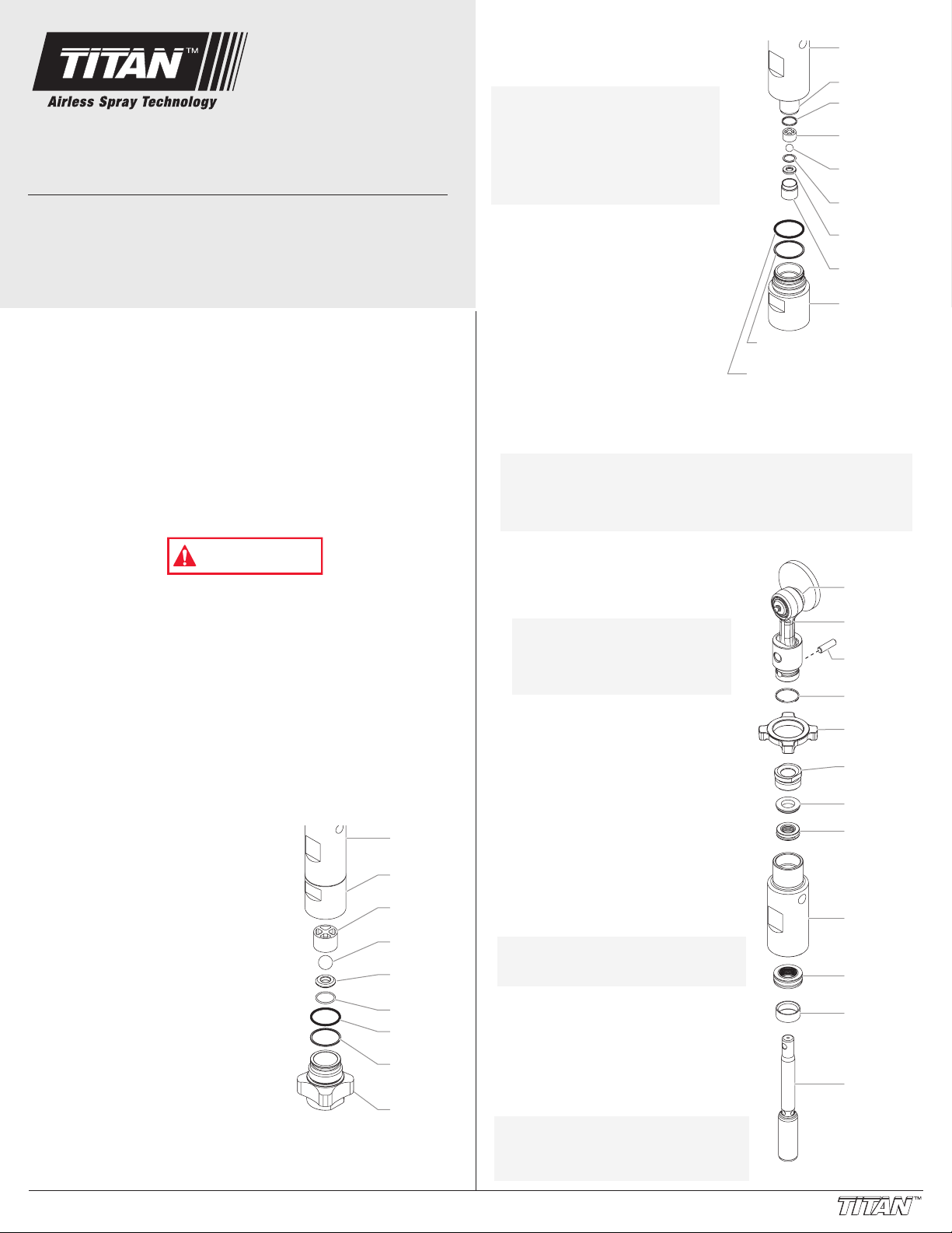
Servicing the Valves
The design of the fluid section allows access to the foot valve and
seat as well as the outlet valve and seat without completely
disassembling the fluid section. It is possible that the valves may not
seat properly because of debris stuck in the foot valve seat or outlet
valve seat. Use the following instructions to clean the valves and
reverse or replace the seats.
1. Loosen and remove the foot valve
housing from the lower housing.
2. Clean out any debris in the foot valve
housing and examine the housing
and the foot valve seat. If the seat is
damaged, reverse or replace the
seat.
3. Using two wrenches, hold the upper
housing at the wrench flats with one
wrench and loosen the lower housing
with the other. Remove the lower
housing.
Foot Valve
Housing
Black
O-Ring
O-Ring
White
Back-Up
Ring
Foot Valve
Seat
Foot Valve
Ball
Foot Valve
Cage
Lower
Housing
Upper
Housing
WARNING
Fluid Section Repacking Kit
For 840i, 1140i, and 3411i airless sprayers
P/N 800-273
4. Using a 3/8” hex wrench, loosen
and remove the outlet valve
retainer from the piston rod.
5. Clean out any debris and
examine the retainer and outlet
valve seat. If the seat is
damaged, reverse or replace
the seat.
6. Remove, clean, and inspect the
outlet valve cage and outlet
valve ball. Replace if they are
worn or damaged (the outlet
valve cage is not included with
this kit but can be ordered
separately).
7. Reassemble the valves by
reversing the steps above. During reassembly of the outlet valve,
use the new outlet valve ball, nylon washer, and outlet valve seal
supplied with this kit. During reassembly of the foot valve, use the
new o-ring and foot valve ball supplied with this kit.
Repacking the Fluid Section
1. Remove the foot valve assembly and
the lower housing using the steps in
the “Servicing the Valves” procedure
above.
2. Slide the retaining ring up on the
slider assembly to expose the
connecting pin.
3. Push the connecting pin back through
the slider assembly and piston. The
connecting pin will fall into a
recessed area of the gear box
housing where it can be retrieved.
4. Tap the knock-off nut with a soft
hammer so that it turns
counterclockwise and loosens.
5. Turn the fluid section
counterclockwise to remove it from
the gear box housing.
6. Place the upper housing upright in a
vise by clamping on the wrench flats.
7. Using a wrench, remove the upper
seal retainer.
8. Slide the piston rod out through the
bottom of the upper housing.
9. Inspect the piston rod for wear and
replace if necessary.
10. Remove the upper and lower
packings from the upper housing.
NOTE: Be careful not to scratch,
score, or otherwise damage
the upper housing during
removal of the packings.
NOTE: Do not over-tighten the
vise. Damage to the upper
housing may occur.
NOTE: The outlet valve does
not need to be
disassembled from
the piston rod for this
procedure.
NOTE: During reassembly, make sure the new black o-
rings and the new white back-up rings between the
upper housing and lower housing as well as
between the lower housing and the foot valve
housing are lubricated with grease and in position.
NOTE: Always service the
outlet valve with the
piston rod attached to
the pump. This will
prevent the piston rod
from rotating during
disassembly of the
outlet valve.
Instruction Sheet
For professional use only
Form No. 313-1875A
White Back-Up
Ring
Black O-Ring
Upper
Housing
Piston Rod
Outlet Valve
Seal
Outlet Valve
Cage
Outlet Valve
Ball
Nylon
Washer
Outlet Valve
Seat
Outlet Valve
Retainer
Lower
Housing
Crankshaft
Slider
Assembly
Connecting
Pin
Retaining
Ring
Knock-Off
Nut
Upper Seal
Retainer
Spacer
Upper
Packing
Upper
Housing
Lower
Packing
Wear Ring
Piston Rod
Page 2
11. Clean the upper housing. Inspect the upper housing for
damage and replace if necessary.
12. Locate the new upper and lower packings and remove the preform tools. Save the upper packing pre-form tool for use as the
piston insertion tool later in this procedure.
13. Pack the areas between the packing lips with grease. Lubricate
the o-rings on the exterior of the packings with grease.
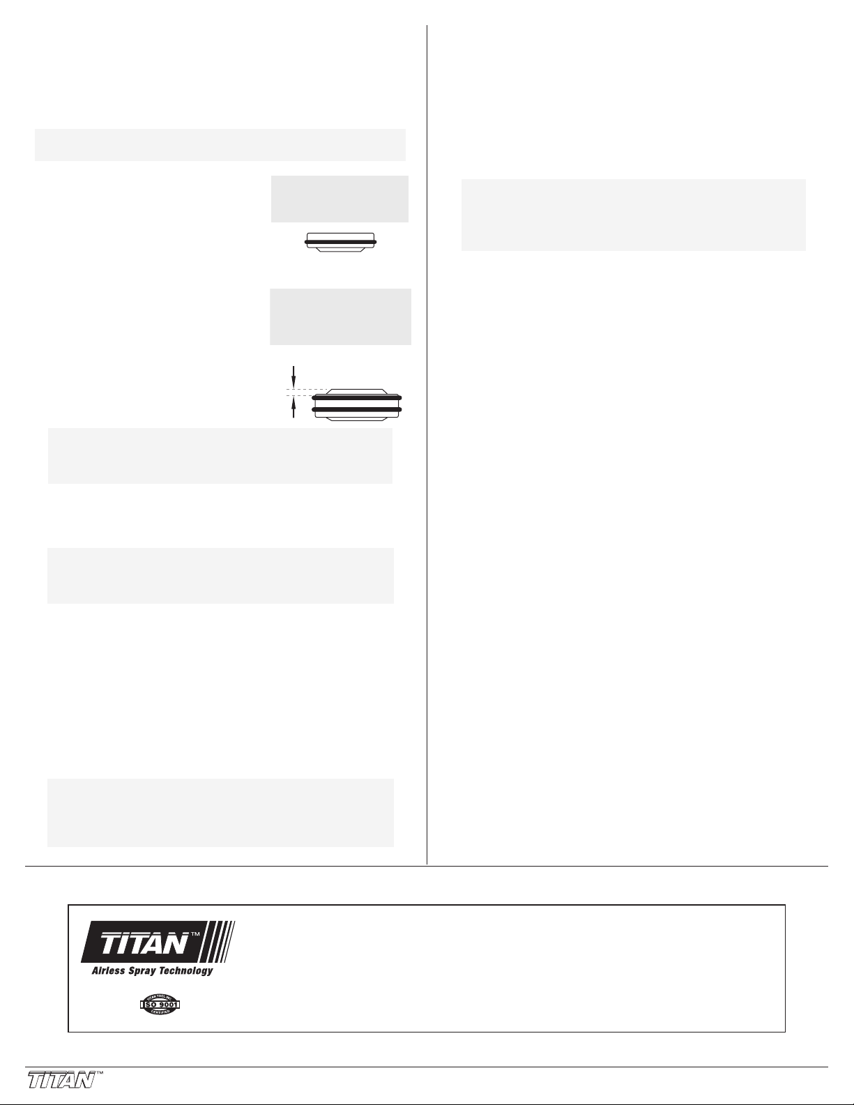
14. Insert the upper packing into the top
of the upper housing with the raised
lip on the packing facing down.
15. Insert the spacer on top of the upper
packing.
16. Thread the upper seal retainer into
the upper housing and torque to 2530 ft. lbs.
17. Insert the lower packing partially into
the bottom of the upper housing so
that the side that has the o-ring
closest to the face of the packing
faces up.
18. Push the lower packing into position
using the lower packing insertion tool
(see Fluid Section Assembly parts list
for lower packing insertion tool P/N).
19. Place the piston insertion tool over the top of the piston rod.
20. Insert the piston rod into the bottom of the upper housing,
through the lower packing, through the upper packing, and out
through the upper seal retainer.
21. Remove the piston insertion tool from the top of the piston rod.
22. Turn the knock-off nut counterclockwise until it is flush against
the upper housing.
23. Lubricate the threads on the upper housing with anti-seize
compound. Remove the upper housing from the vise.
24. Thread the upper housing into the gear box housing, turning
clockwise. When the connecting pin hole on the piston rod lines
up with the hole in the slider assembly, insert the connecting
pin.
25. Slide the retaining ring down over the connecting pin.
26. Continue to turn the upper housing clockwise until the knock-off
nut is flush against the gear box housing.
NOTE: If the nipple on the upper housing does not
face the back of the unit, turn the upper
housing counterclockwise until the nipple
faces the back of the unit. Do not turn the
upper housing more than one full turn.
NOTE: When repacking the fluid section, make sure
the raised lip on the bottom of the lower
packing is fully outside the packing around the
piston rod after insertion of the piston rod.
NOTE: Coat the piston insertion tool (i.e., upper
packing pre-form tool) and the piston rod with
grease before inserting them into the pump
block.
Install lower packing with
the side that has the o-ring
closest to the face of the
packing facing up.
Closer
Top
NOTE: The factory-installed packings are black in color.
The replacement packings in this kit are white.
2 0602 © 2002 Titan Tool Inc. All Rights Reserved.
Install upper packing
with raised lip
facing down.
Raised Lip
27. Once the nipple is positioned, turn the knock-off nut clockwise
until it contacts the gear box housing.
28. Tap the knock-off nut with a soft hammer to tighten it against the
gear box housing.
29. Making sure that the new black o-ring and new white back-up
ring are lubricated and in place, thread the lower housing into
the upper housing. Using two wrenches, hold the upper
housing at the wrench flats with one wrench and tighten the
lower housing with the other.
30. Attach the high-pressure hose to the nipple on the back of the
housing and tighten with a wrench. Do not kink the hose.
NOTE: For low rider units, make sure the hose does
not touch the cart frame. If it does, reposition
the nipple by turning the upper housing until
the hose is clear of the frame and the nipple is
within 45º of the back of the unit.
31. Making sure that the new black o-ring and new white back-up
ring are lubricated and in place, reassemble the foot valve
assembly and and thread it into the lower housing. During
reassembly of the foot valve, use the new o-ring and foot valve
ball supplied with this kit. Tighten securely.
32. Thread the siphon tube/siphon set into the foot valve and tighten
securely. Make sure to wrap the threads on the down tube/siphon
hose adapter with PTFE tape before assembly.
33. Replace the return hose into the clamp on the siphon tube.
34. Place the front cover on the gearbox housing and secure in
position using the four front cover screws.
35. Turn on the sprayer by following the procedure in the
“Operation” section of the Owner’s Manual and check for leaks.
United States Sales & Service
1-800-526-5362
Fax 1-800-528-4826
556 Commerce Street
Franklin Lakes, NJ 07417
www.titantool.com
Canadian Branch
1-800-565-8665
Fax 1-905-856-8496
200 Trowers Road, Unit 7B
Woodbridge, Ontario L4L 5Z8
International
1-201-337-1240
Fax 1-201-405-7449
556 Commerce Street
Franklin Lakes, NJ 07417 USA
 Loading...