

Page 1
PowrBeast
Airless, high-pressure
sprAying unit
Airless hochdruckspritzgerät
operAting MAnuAl
- d - BetrieBsAnleitung 34
- F - Mode d’eMploi 66
groupe de projection à
hAute pression
Models:
PowrBeast 4700 (120V) 0537000
PowrBeast 4700 (Gas) 0537001
PowrBeast 7700 (230V) 0537003
PowrBeast 7700 (Gas) 0537005
PowrBeast 9700 (Gas) 0537007
PowrBeast 4700T (120V) 0537010
0217 • Form No. 0537810B
Page 2
original operating manual
Airless units develop extremely high spraying pressures.
1
PowrBeast
Warning!
Attention: Danger of injury by injection!
Never put your ngers, hands or any other parts of the body into
the spray jet!
Never point the spray gun at yourself, other persons or animals.
Never use the spray gun without safety guard.
Do not treat a spraying injury as a harmless cut. In case of injury
to the skin through coating materials or solvents, consult a doctor
immediately for quick and expert treatment. Inform the doctor
about the coating material or solvent used.
2
3
The operating instructions state that the following points must
always be observed before starting up:
1. Faulty units must not be used.
2. Secure Titan spray gun using the trigger lock on the trigger.
3. Ensure that the unit is properly earthed.
4. Check allowable operating pressure of high-pressure hose and spray gun.
5. Check all connections for leaks.
The instructions regarding regular cleaning and maintenance of
the unit must be strictly observed.
Before any work is done on the unit or for every break in work the
following rules must be observed:
1. Release the pressure from spray gun and hose.
2. Secure the Titan spray gun using the trigger lock on the trigger.
3. Switch o unit.
Be safety conscious!
2
Page 3

contents
PowrBeast
1 SAFETY REGULATIONS FOR AIRLESS
SPRAYING ______________________________ 4
1.1 Explanation of symbols used _____________________4
1.2 Safety hazards ________________________________4
1.3 Setup on an uneven surface _____________________6
1.4 Electrical safety _______________________________6
1.5 Gasoline engine safety__________________________6
1.6 Fueling (gas engine) ___________________________7
2 MAIN AREAS OF APPLICATION ____________ 8
2.1 Application ___________________________________ 8
2.2 Coating materials ______________________________ 8
3 DESCRIPTION OF UNIT ___________________ 9
3.1 Airless process ________________________________9
3.2 Functioning of the unit _________________________9
3.3 System diagram - gasoline PowrBeast units ________ 10
3.4 System diagram - electric PowrBeast units _________ 11
3.5 Technical data for PowrBeast units _______________ 12
3.6 Transportation _______________________________13
4 OPERATION ____________________________ 13
4.1 Setup ______________________________________13
4.2 Starting the engine (gas models) ________________15
4.3 Preparing a new sprayer _______________________15
4.4 Preparing to paint ____________________________16
4.5 Painting ____________________________________17
4.6 Pressure relief procedure _______________________ 17
5 SPRAYING _____________________________18
5.1 Cleaning a clogged tip _________________________ 18
5.2 Interruption of work __________________________19
5.3 Handling the high pressure hose ________________19
6 CLEANUP ______________________________20
6.1 Special cleanup instructions for use with
ammable solvents ___________________________20
6.2 Cleaning the sprayer __________________________20
6.3 Cleaning the outside of the sprayer ______________20
6.4 Cleaning the lter screen _______________________ 21
6.5 Cleaning the airless spray gun __________________21
7 MAINTENANCE _________________________22
7.1 Daily maintenance ____________________________ 22
7.2 Lubricating the upper packings _________________22
7.3 Maintaining the lter assembly __________________ 22
7.4 Maintaining the hydraulic system ________________ 23
7.5 Maintaining the uid section ___________________24
7.6 High pressure hose ___________________________24
7.7 Basic engine maintenance______________________25
7.8 Servicing the hydraulic motor ___________________ 26
7.9 Servicing the uid section ______________________28
7.10 Replacing the belt ____________________________30
8 TROUBLESHOOTING ____________________31
8.1 Airless gun __________________________________31
8.2 Fluid section _________________________________ 31
8.3 Hydraulic motors _____________________________32
8.4 Spray patterns _______________________________33
ACCESSORIES AND SPARE PARTS _____________98
Spare parts list for the main assembly I ______________ 98/99
Spare parts list for the main assembly II ___________ 100/101
Spare parts list for the cart assembly ______________ 102/103
Spare parts list for the hydraulic system ___________ 104/105
Spare parts list for the uid section •
PowrBeast 4700 / PowrBeast 4700T ______________ 106/107
Spare parts list for the uid section •
PowrBeast 7700 / 9700 _________________________ 108/109
Spare parts list for the hydraulic motor assembly ___ 110/111
Spare parts list for the high-pressure lter _________ 112/113
Spare parts list for bleed valve assembly ______________114
Spare parts list for bleed valve assembly, heavy materials _115
Spare parts list for solenoid assembly _____________ 116/117
CONNECTION DIAGRAM 120V ______________118
CONNECTION DIAGRAM 230V ______________119
CONNECTION DIAGRAM GAS ENGINE _______120
HYDRAULIC DIAGRAM ______________________121
ACCESSORIES FOR POWRBEAST UNITS ___122/123
WARRANTY ________________________________ 125
3
Page 4
safety precautions
At
i
A high pressure stream produced by this
equipment can pierce the skin and underlying
tissues, leading to serious injury and possible
or solvents, consult a doctor immediately for
quick and expert treatment. Inform the doctor
1 SAFETY REGULATIONS FOR AIRLESS
SPRAYING
1.1
EXPLANATION OF SYMBOLS USED
PowrBeast
1.2 SAFETY HAZARDS
This manual contains information that must be read and
understood before using the equipment. When you come to
an area that has one of the following symbols, pay particular
attention and make certain to heed the safeguard.
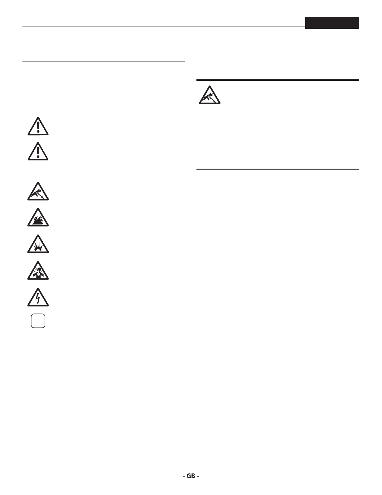
This symbol indicates a potential hazard
that may cause serious injury or loss of life.
Important safety information will follow.
This symbol indicates a potential hazard
to you or to the equipment. Important
tention
information that tells how to prevent
damage to the equipment or how to avoid
causes of minor injuries will follow.
Danger of skin injection
Danger of re from solvent and paint fumes
Danger of explosion from solvent, paint
fumes and incompatible materials
Danger of injury from inhalation of harmful
vapors
Danger of injury from electric shock
Notes give important information which
should be given special attention.
HAZARD: INJECTION INJURY
amputation.
Do not treat a spraying injury as a harmless cut. In
case of injury to the skin through coating materials
about the coating material or solvent used.
PREVENTION:
• NEVER aim the gun at any part of the body.
• NEVER allow any part of the body to touch the uid stream.
DO NOT allow body to touch a leak in the uid hose.
• NEVER put your hand in front of the gun. Gloves will not
provide protection against an injection injury.
• ALWAYS lock the gun trigger, shut the uid pump o and
release all pressure before servicing, cleaning the tip guard,
changing tips, or leaving unattended. Pressure will not be
released by turning o the engine. The PRIME/SPRAY valve
or pressure bleed valve must be turned to their appropriate
positions to relieve system pressure.
• ALWAYS keep tip guard in place while spraying. The tip
guard provides some protection but is mainly a warning
device.
• ALWAYS remove the spray tip before ushing or cleaning
the system.
• NEVER use a spray gun without a working trigger lock and
trigger guard in place.
• All accessories must be rated at or above the maximum
operating pressure range of the sprayer. This includes
spray tips, guns, extensions, and hose.
4
Page 5
safety precautions
The paint hose can develop leaks from wear,
Flammable vapors, such as solvent and paint
PowrBeast
HAZARD: HIGH PRESSURE HOSE
kinking and abuse. A leak can inject material into
the skin. Inspect the hose before each use.
PREVENTION:
• Avoid sharp bending or kinking of the high-pressure hose.
The smallest bending radius amounts to about 20 cm.
• Do not drive over the high-pressure hose. Protect against
sharp objects and edges.
• Replace any damaged high-pressure hose immediately.
• Never repair damaged high-pressure hoses yourself!
• Electrostatic charging of spray guns and the high-pressure
hose is discharged through the high-pressure hose. For this
reason the electric resistance between the connections of
the high-pressure hose must be equal to or lower than
1M.
• For reasons of function, safety and durability use only
original Titan high-pressure hoses.
• Before each use, check all hoses for cuts, leaks, abrasion
or bulging of cover. Check for damage or movement of
couplings. Immediately replace the hose if any of these
conditions exist. Never repair a paint hose. Replace it with
another earthed high-pressure hose.
• Make sure power cord, air hose and spray hoses are routed
in such a manner to minimize slip, trip and fall hazard.
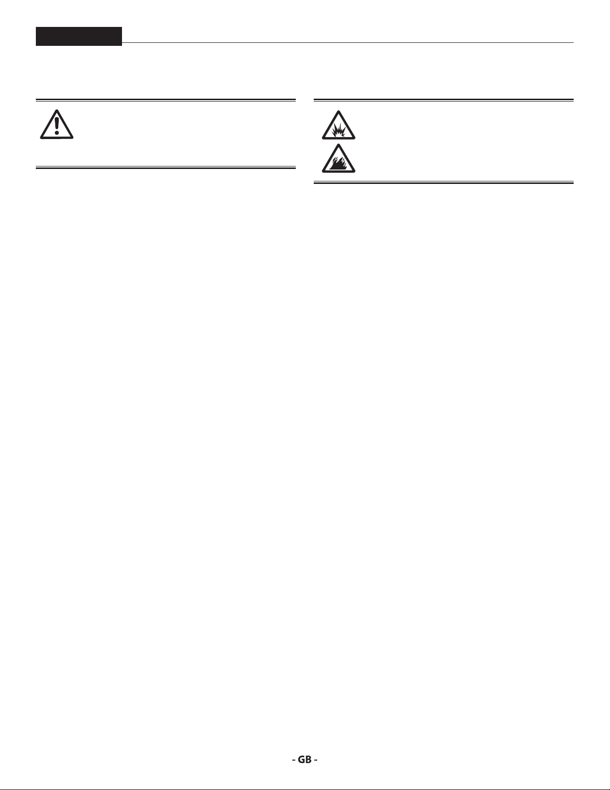
HAZARD: EXPLOSION OR FIRE
vapors, in work area can ignite or explode.
PREVENTION:
• Use equipment only in well ventilated area. Keep a good
supply of fresh air moving through the area to keep the air
within the spray area free from accumulation of ammable
vapors. Keep pump assembly in well ventilated area. Do
not spray pump assembly.
• Electric models only - Do not use materials with a ashpoint
below 38º C (100º F). Flashpoint is the temperature at which
a uid can produce enough vapors to ignite.
• Gas models only - Do not ll fuel tank while engine is
running or hot; shut o engine and allow to cool. Fuel is
ammable and can ignite or explode if spilled on a hot
surface.
• Eliminate all ignition sources, such as pilot lights, cigarettes,
portable electric lamps and plastic drop cloths (potential
static arc).
• Keep work area free of debris, including solvent, rags and
gasoline.
• Do not plug or unplug power cords, or turn power or light
switches on or o when ammable vapors are present.
• Ground equipment and conductive objects in work
area. Make sure the grounding cable (not equipped) is
connected from the grounding lug to a true earth ground.
• Use only grounded hoses.
• Hold spray gun rmly to the side of a grounded pail when
triggering into pail.
• If there is static sparking or if you feel a shock, stop
operation immediately.
• Know the contents of the paint and solvents being sprayed.
Read all material Safety Data Sheets (SDS) and container
labels provided with the paints and solvents. Follow the
paint and solvent manufacturer’s safety instructions.
• Do not use a paint or solvent containing halogenated
hydrocarbons. Such as chlorine, bleach, mildewcide,
methylene chloride and trichloroethane. They are not
compatible with aluminum. Contact the coating supplier
about compatibility of material with aluminum.
• Keep a re extinguisher in work area.
5
Page 6
safety precautions
Paints, solvents, and other materials can be
harmful if inhaled or come in contact with body.
Vapors can cause severe nausea, fainting, or
PowrBeast
HAZARD: HAZARDOUS VAPORS
poisoning.
PREVENTION:
• Wear respiratory protection when spraying. Read all
instructions supplied with the mask to be sure it will
provide the necessary protection.
• All local regulations regarding protection against
hazardous vapors must be observed.
• Wear protective eyewear.
• Protective clothing, gloves and possibly skin protection
cream are necessary for the protection of the skin. Observe
the regulations of the manufacturer concerning coating
materials, solvents and cleaning agents in preparation,
processing and cleaning units.
HAZARD: GENERAL
This product can cause severe injury or property
damage.
PREVENTION:
• Follow all appropriate local, state, and national codes
governing ventilation, re prevention, and operation.
• Pulling the trigger causes a recoil force to the hand that is
holding the spray gun. The recoil force of the spray gun
is particularly powerful when the tip has been removed
and high pressure has been set on the airless pump. When
cleaning without a spray tip, set the pressure control knob
to the lowest pressure.
• Use only manufacturer authorized parts. User assumes all
risks and liabilities when using parts that do not meet the
minimum specications and safety devices of the pump
manufacturer.
• ALWAYS follow the material manufacturer’s instructions
for safe handling of paint and solvents.
• Clean up all material and solvent spills immediately to
prevent slip hazard.
• Wear ear protection. This unit can produce noise levels
above 85 dB(A).
• Never leave this equipment unattended. Keep away from
children or anyone not familiar with the operation of airless
equipment.
• Do not spray on windy days.
• The device and all related liquids (i.e. hydraulic oil) must be
disposed of in an environmentally friendly way.
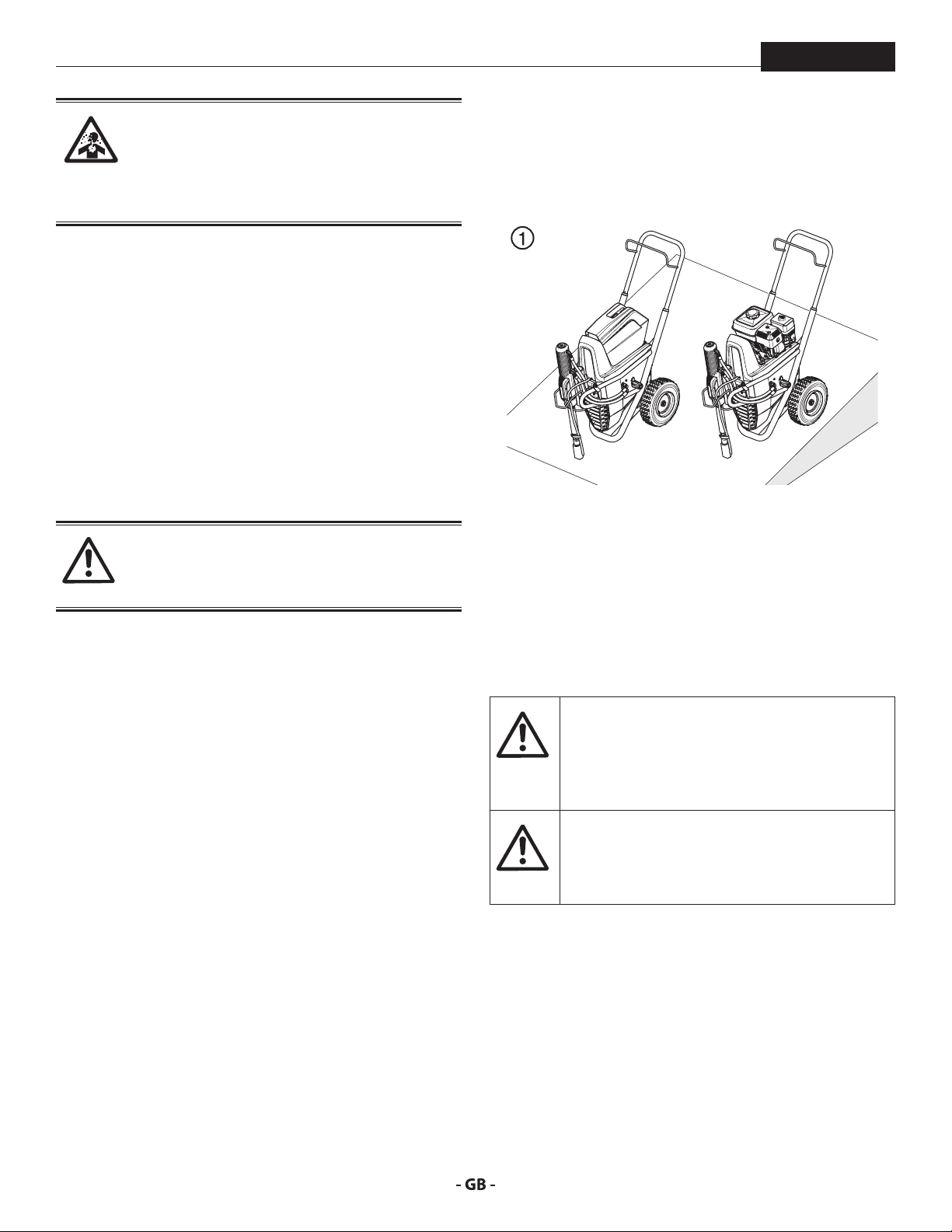
1.3 SETUP ON AN UNEVEN SURFACE
The front end must always point downwards in order to avoid
sliding away.
If possible do not use the unit on an inclined surface since the
unit tends to wander due to the resulting vibrations.
1.4 ELECTRIC SAFETY
Electric models must be grounded/earthed. In the event
of an electrical short circuit, grounding/earthing reduces
the risk of electric shock by providing an escape wire for the
electric current. This product is equipped with a cord having
an grounding/earthing wire with an appropriate grounding/
earthing plug. Connection to the power cord only through a
special feed point, e.g. through an error protection insallation
with INF < 30 mA.
DANGER — Work or repairs at the electrical
equipment may only be carried out by a skilled
electrician. No liability is assumed for incorrect
installation. Switch the unit o. Before all repair
work, unplug the power plug from the outlet.
Danger of short-circuits caused by water
ingressing into the electrical equipment. Never
spray down the unit with high-pressure or highpressure steam cleaners.
1.5 GASOLINE ENGINE SAFETY
1. Gas engines are designed to give safe and dependable
service if operated according to instructions. Read and
understand the engine manufacturer’s Owner’s Manual
before operating the engine. Failure to do so could result
in personal injury or equipment damage.
2. To prevent re hazards and to provide adequate
ventilation, keep the engine at least 1 meter (3 feet) away
from buildings and other equipment during operation. Do
not place ammable objects close to the engine.
6
Page 7
safety precautions
At
i
i
PowrBeast
3. People who are not operating the device must stay away
from the area of operation due to a possibility of burns from
hot engine components or injury from any equipment the
engine may be used to operate.
4. Know how to stop the engine quickly, and understand the
operation of all controls. Never permit anyone to operate
the engine without proper instructions.
5. Gasoline is extremely ammable and is explosive under
certain conditions.
6. Refuel in a well-ventilated area with the engine stopped.
Do not smoke or allow ames or sparks in the refueling
area or where gasoline is stored.
7. Do not overll the fuel tank. After refueling, make sure the
tank cap is closed properly and securely.
8. Be careful not to spill fuel when refueling. Fuel vapor or
spilled fuel may ignite. If any fuel is spilled, make sure the
area is dry before starting the engine.
9. Never run the engine in an enclosed or conned area.
Exhaust contains poisonous carbon monoxide gas;
exposure may cause loss of consciousness and may lead
to death.
10. The muer becomes very hot during operation and
remains hot for a while after stopping the engine. Be
careful not to touch the muer while it is hot. To avoid
severe burns or re hazards, let the engine cool before
transporting it or storing it indoors.
11. Never ship/transport sprayer with gasoline in the tank.
DO NOT use this equipment to spray water or
acid.
Do not lift by cart handle when loading or
unloading.
tention
Device is very heavy. Three-person lift is required.
1.6 FUELING GAS ENGINE
Gasoline is extremely ammable and is explosive
under certain conditions.
If “spark knock” or “pinging” occurs at a steady
engine speed under normal load, change brands
of gasoline. If spark knock or pinging persists,
consult an authorized dealer of the engine
manufacturer. Failure to do so is considered
misuse, and damage caused by misuse is not
covered by the engine manufacturer’s limited
warranty.
Occasionally you may experience light spark
knock while operating under heavy loads. This
is no cause for concern, it simply means your
engine is operating eciently.
• Unleaded fuel produces fewer engine and spark plug
deposits and extends the life of the exhaust system
components.
• Never use stale or contaminated gasoline or an oil/gasoline
mixture. Avoid getting dirt, dust, or water in the fuel tank.
GASOLINES CONTAINING ALCOHOL
If you decide to use a gasoline containing alcohol (gasohol), be
sure its octane rating is at least as high as that recommended
by the engine manufacturer. There are two types of “gasohol”:
one containing ethanol, and the other containing methanol.
Do not use gasohol that contains more than 10% ethanol. Do
not use gasoline containing methanol (methyl or wood alcohol)
that does not also contain co-solvents and corrosion inhibitors
for methanol. Never use gasoline containing more than 5%
methanol, even if it has co-solvents and corrosion inhibitors.
Fuel system damage or engine performance
problems resulting from the use of fuels that
contain alcohol is not covered under the
warranty. The engine manufacturer cannot
endorse the use of fuels containing methanol
since evidence of their suitability is incomplete
at this time.
Before buying gasoline from an unfamiliar
station, try to nd out if the gasoline contains
alcohol. If it does, conrm the type and
percentage of alcohol used. If you notice any
undesirable operating characteristics while using
a gasoline that contains alcohol, or one that you
think contains alcohol, switch to a gasoline that
you know does not contain alcohol.
FUEL SPECIFICATIONS
Use automotive gasoline that has a pump octane number of 86
or higher, or that has a research octane number of 91 or higher.
Use of a lower octane gasoline can cause persistent “pinging” or
heavy “spark knock” (a metallic rapping noise) which, if severe,
can lead to engine damage.
7
Page 8
main areas of application
i
i
2 MAIN AREAS OF APPLICATION
PowrBeast
2.1
The main area of application are thick layers of highly viscous
coating material for large areas and a high consumption of
material.
Priming and nal coating of large areas, sealing, impregnation,
construction sanitation, façade protection and renovation, rust
protection and building protection, roof coating, roof sealing,
concrete sanitation, as well as heavy corrosion protection.
EXAMPLES OF OBJECTS TO BE SPRAYED
Large-scale construction sites, cooling towers, bridges, sewage
treatment plants and terraces.
APPLICATION
2.2 COATING MATERIALS
PROCESSIBLE COATING MATERIALS
Diluting lacquers and paints or those containing solvents, twocomponent coating materials, dispersion and latex paints.
No other materials should be used for spraying without Titan‘s
approval.
Pay attention to the Airless quality of the coating
materials to be processed.
VISCOSITY
The unit is able to process coating materials with up to 50.000
/ 65.000 mPas. If highly viscous coating materials cannot be
taken in or the performance of the unit is to low, the paint must
be diluted in accordance with the manufacturer‘s instructions.
Attention: Make sure, when stirring up with
motor-driven agitators that no air bubbles are
stirred in. Air bubbles disturb when spraying and
can, in fact, lead to interruption of operation.
COATING MATERIALS WITH ABRASIVE MATERIALS
These particles have a strong wear and tear eect on valves and
tips, but also on the spray gun. This impairs the durability of
these wearing parts considerably.
TWOCOMPONENT COATING MATERIAL
The appropriate processing time must be adhered to exactly.
Within this time rinse through and clean the unit meticulously
with the appropriate cleaning agents.
FILTERING
Sucient ltering is required for fault-free operation. The unit
is equipped with a suction lter, an insertion lter in the spray
gun and a high pressure lter on the unit. Regular inspection
of these lters for damage or soiling is urgently recommended.
8
Page 9
description of unit
i
2
PowrBeast
3 DESCRIPTION OF UNIT
3.1
A piston pump takes in the coating material by suction and
conveys it to the tip. Pressed through the tip at a pressure of
up to a maximum of 3300 PSI (228 bar, 22.8 MPa), the coating
material is atomised. This high pressure has the eect of micro
ne atomization of the coating material.
As no air is used in this process, it is described as an AIRLESS
process.
This method of spraying has the advantages of nest
atomization, cloudless operation and a smooth, bubble-free
surface. As well as these, the advantages of the speed of work
and convenience must be mentioned.
AIRLESS PROCESS
3.2 FUNCTIONING OF THE UNIT
The following section contains a brief description of the
technical construction for better understanding of the function
of the unit.
This manual gives information for both electric
motor and gasoline engine PowrBeast models.
TITAN PowrBeast are high-pressure spraying units driven by
either a gasoline engine or electric motor.
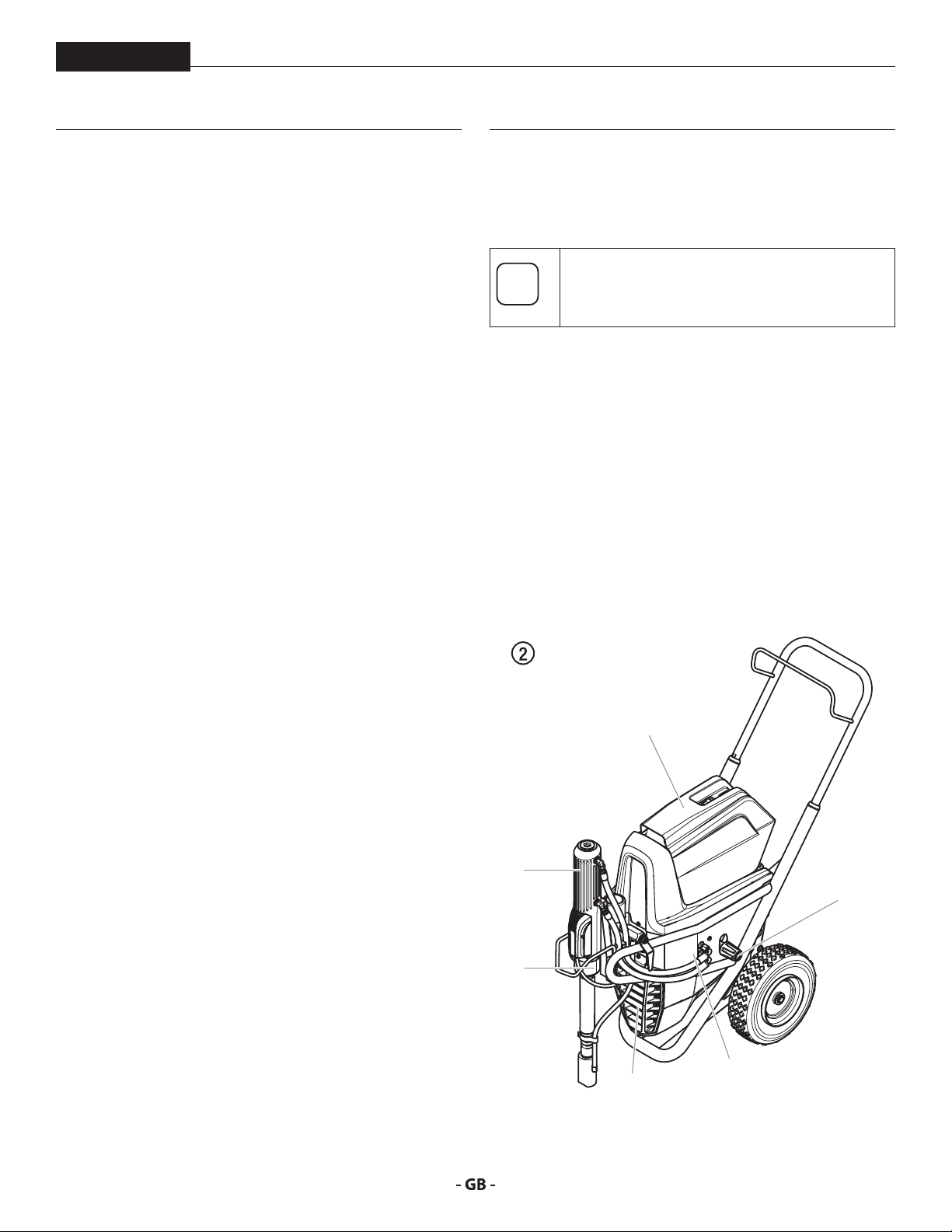
The gasoline engine or electric motor (g. 1, item 1) drives the
hydraulic pump (3) by means of a V-belt which is under the belt
cover (2). Hydraulic oil ows to the hydraulic motor (4) and then
moves the piston up and down in the material feed pump (5).
The inlet valve is opened automatically by the upwards
movement of the piston. The outlet valve is opened when the
piston moves downward.
The coating material ows under high pressure through the
high-pressure hose to the spray gun. When the coating material
exits from the tip it atomizes.
The pressure control valve (6) controls the volume and the
operating pressure of the coating material.
1
4
6
5
3
9
Page 10
description of unit
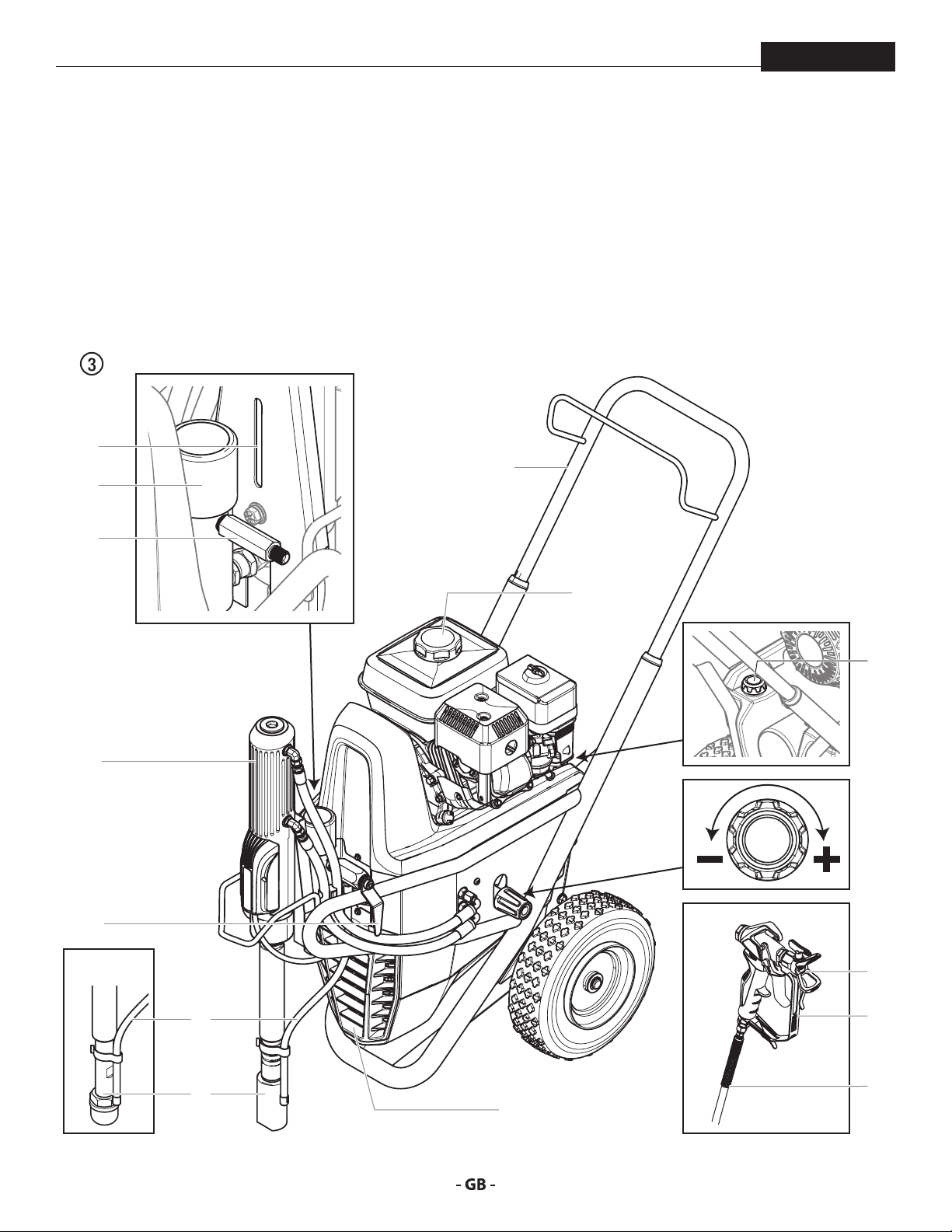
3.3 SYSTEM DIAGRAM GASOLINE POWRBEAST UNITS
PowrBeast
1. Extractable handle
2. Oil cup for separating oil (separating
oil prevents increased wear and tear
of the packings)
3. High-pressure lter
4. High-pressure hose outlet
5. Hydraulic motor
2
3
4
6. Relief valve handle:
Turn left for circulation k
Turn right for spray p
7. Bleed hose
8. Suction tube
9. V-belt under the belt cover
10. Gasoline engine
1
11. Oil measuring stick
12. Pressure control knob
13. Tip guard with airless tip
14. Spray gun
15. High-pressure hose
10
5
6
4700
11
12
13
7
8
14
15
9
10
Page 11
description of unit
PowrBeast
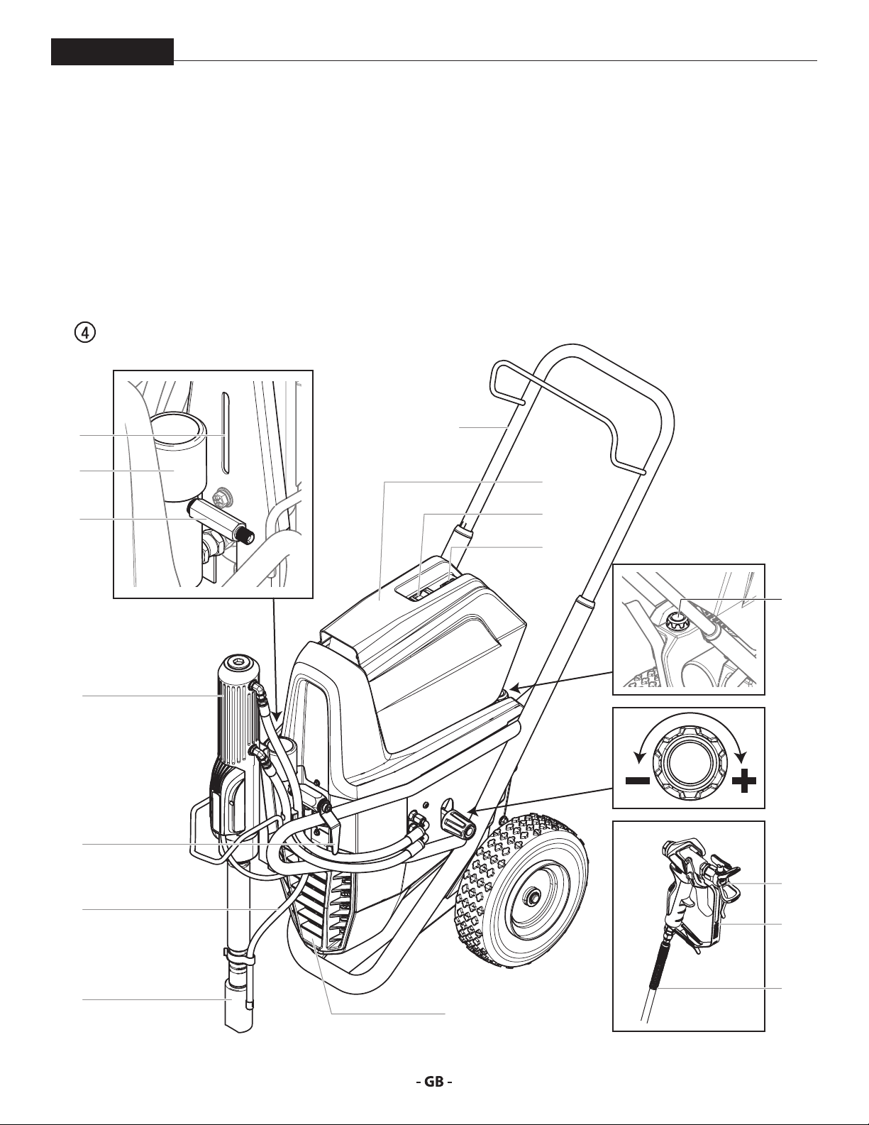
3.4 SYSTEM DIAGRAM ELECTRIC POWRBEAST UNITS
1. Extractable handle
2. Oil cup for separating oil (separating
oil prevents increased wear and tear
of the packings)
3. High-pressure lter
4. High-pressure hose outlet
5. Hydraulic motor
2
3
4
6. Relief valve handle:
Turn left for circulation k
Turn right for spray p
7. Bleed hose
8. Suction tube
9. V-belt under the belt cover
10. Electric motor
1
11. ON/OFF swtich
12. Control lamp that shows unit
operational
13. Oil measuring stick
14. Pressure control knob
15. Tip guard with airless tip
16. Spray gun
17. High-pressure hose
10
11
12
13
5
14
6
15
7
16
17
8
9
11
Page 12

description of unit
3.5 TECHNICAL DATA
PowrBeast
PowrBeast 4700T
(120V)
Gasoline engine, power
Honda -------- --------
Fuel Capacity
-------- -------- 0.82 US gal (3.1 l) -------- 0.82 US gal (3.1 l) 1.6 US gal (6.06 l)
Voltage
~ 120V, 50/60 Hz ~ 120V, 50/60 Hz -------- ~ 230V, 50/60 Hz -------- --------
Capacity
1.3 kW 1.3 kW -------- 3.1 kW -------- --------
Power Cord
3 x 2.5 mm – 6 m 3 x 2.5 mm – 6 m -------- 3 x 2.5 mm – 6 m -------- --------
Current Protection
15 A 15 A -------- 15 A -------- --------
Max. operating pressure
22.8 MPa (3300 PSI) 22.8 MPa (3300 PSI) 22.8 MPa (3300 PSI) 24.8 MPa (3600 psi) 22.8 MPa (3300 PSI) 22.8 MPa (3300 PSI)
Max. sound pressure level
80 dB (A)* 80 dB (A)* 92 dB (A)* 80 dB (A)* 92 dB (A)* 98 dB (A)*
Max. size of tip with a spray gun
1-gun 0.035” – 0.89 mm 0.035” – 0.89 mm 0.041” – 1.04 mm 0.043” – 1.09 mm 0.047” – 1.19 mm 0.055” – 1.40 mm
2-gun 0.023” – 0.58 mm 0.023” – 0.58 mm 0.029” – 0.73 mm 0.031” – 0.79 mm 0.033” – 0.84 mm 0.039” – 0.99 mm
3-gun 0.019” – 0.48 mm 0.019” – 0.48 mm 0.021” – 0.53 mm 0.023” – 0.58 mm 0.027” – 0.68 mm 0.031” – 0.79 mm
4-gun -------- -------- 0.019” – 0.48 mm 0.021” – 0.53 mm 0.023” – 0.58 mm 0.027” – 0.68 mm
Max. volume ow
1.25 gal (4.75 l)/min 1.25 gal (4.75 l)/min 1.60 gal (6.00 l)/min 1.60 gal (6.00 l)/min 2.00 gal (7.60 l)/min 3.00 gal (11.4 l)/min
Weight
187 lbs (85 kg) 181 lbs (82 kg) 173 lbs (78 kg) 187 lbs (85 kg) 179 lbs (81 kg) 199 lbs (90 kg)
Suction system
submersible standard standard submersible submersible submersible
Max. viscosity
Dimensions L x W x H
Max. temperature of the coating material
Filter insert (standard equipment)
-------- 50 mesh, 18 in 50 mesh, 18 in 0 mesh, 18 in 50 mesh, 18 in 5 mesh, 18 in
Hydraulic oil lling quantity
Max. tire pressure
Special high-pressure hose
DN 10 mm, 15 m (50’
x 3/8”), connection
thread NPSM 1/4
PowrBeast 4700
(120V)
50.000 mPa·s 65.000 mPa·s
PowrBeast 4700
(gas)
163cc, 4.9 Hp, 3.6 kW -------- 196cc, 5.6 Hp, 4.1 kW 270cc, 8.4 Hp, 6.2 kW
43” x 25” x 34” (1090 x 660 x 866 mm)
109ºF (43° C)
5.9 l (1.56 gal) CoolFlo
0.2 MPa (2 bar, 30 PSI)
DN 6 mm, 15 m (50’ x 1/4”), connection thread NPSM 1/4
PowrBeast 7700
(230V)
PowrBeast 7700
(gas)
PowrBeast 9700
(gas)
* Place of measurement: 1 m distance from unit and 1.60 m above reverberant oor, 120 bar (12 MPa) operating pressure.
12
Page 13
description of unit / operation
i
PowrBeast
4 OPERATION
OPERATING TEMPERATURE
This equipment will operate correctly in its intended ambient,
at a minimum between +50ºF (10°C) and 104ºF (+40°C).
RELATIVE HUMIDITY
The equipment will operate correctly within an environment
at 50% RH, 104ºF (+40°C). Higher RH may be allowed at lower
temperatures.
Measures shall be taken by the Purchaser to avoid the harmful
eects of occasional condensation.
ALTITUDE
This equipment will operate correctly up to 2100 m above
mean sea level.
TRANSPORTATION AND STORAGE
This equipment will withstand, or has been protected against,
transportation and storage temperatures of -13ºF (-25°C) to
131ºF (+55°C) and for short periods up to 150ºF (+70°C).
It has been packaged to prevent damage from the eects of
normal humidity, vibration and shock.
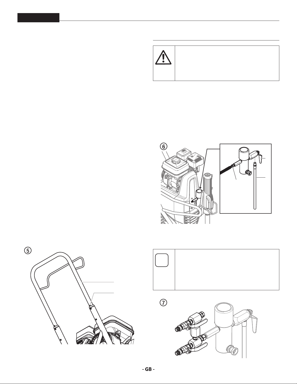
4.1 SETUP
1. Make sure the bleed hose (Fig. 6, item 1) is threaded into
2. Attach a minimum of 50’ (15 m) of nylon airless spray hose
This equipment produces a uid stream at
extremely high pressure. Read and understand
the warnings in the Safety Precautions section
at the front of this manual before operating this
equipment.
the bleed valve (2). It has factory installed PTFE tape on
the tting and should be tightened wrench tight.
(3) to the sprayer. Do not use PTFE tape or thread sealant
on the spray hose connection.
2
3.6 TRANSPORTATION
TRANSPORTATION IN VEHICLE
Secure the unit with a suitable fastening.
PUSHING OR PULLING THE UNIT
Pull out the handle (Fig. 5, Item 1) until it will come no further.
Insert the handle – push the buttons (2) on the cart, and then
push in the handle.
1
2
1
3
3. Attach an airless spray gun to the spray hose. Do not
attach the tip to the spray gun yet. Remove the tip if it is
already attached.
For multiple gun operation, connect a multiple
gun manifold to the single gun outlet. Connect
a hose and gun to each outlet. Make sure
the second gun outlet remains plugged. See
“Technical Data”, Section 3.5 to determine
number of guns and maximum spray tip sizes.
13
Page 14
operation
At
At
PowrBeast
4. Fill the oil cup 1/2 full with Piston Lube (P/N 314-480). This
extends packing life.
Piston Lube prevents increased wear and tear to
the packings.
tention
5. Check the hydraulic uid level daily before starting the
sprayer. The hydraulic uid level should be touching
the bottom of the dipstick. Refer to the Maintenance
section of this manual for hydraulic system maintenance
instructions.
Proper grounding/earthing is important. The
passage of some materials through the nylon
uid hose will build up a static electric charge,
which if discharged, could ignite solvent vapors
present and create an explosion.
9. Strain all paints with a nylon strainer to ensure trouble
free operation and freedom from frequent cleaning of the
suction lter and gun lter.
10. Make sure the spray area is well ventilated to prevent
hazardous operation with volatile solvents or exhaust
fumes.
If lacquer or other ammable materials are to be
sprayed, ALWAYS locate the sprayer outside the
immediate spraying area. Failure to do so may
cause an explosion.
11. Locate the sprayer outside the immediate spraying area to
avoid clogged air intake of the engine with overspray.
Use of Titan’s Coolo™ Hydraulic Fluid (P/N 430-
361) is mandatory in the hydraulic system. Do
tention
6. For gas models, check the engine oil level daily before
7. For electric models, use a 15 amp service outlet. Always
8. Make sure the sprayer is grounded/earthed. All sprayers are
not use any other hydraulic uid. Use of any
other hydraulic uid may seriously damage the
hydraulic system and will void the warranty.
starting the sprayer. The gasoline engine oil level is
determined by the engine manufacturer. Refer to the
engine manufacturer’s service manual supplied with this
sprayer.
locate the electric model within 10 to 15 feet of the service
outlet. Use a short electric cable and a long paint hose.
Any extension cord will create some voltage drop. If an
extension cord is necessary, use only a grounded 3-wire
12-gauge extension cord.
equipped with a grounding/earthing lug. A grounding/
earthing cable should be used to connect the sprayer to a
true earth ground. Check your local electrical regulations
for detailed grounding/earthing instructions.
14
Page 15
operation
i
i
i
At
PowrBeast
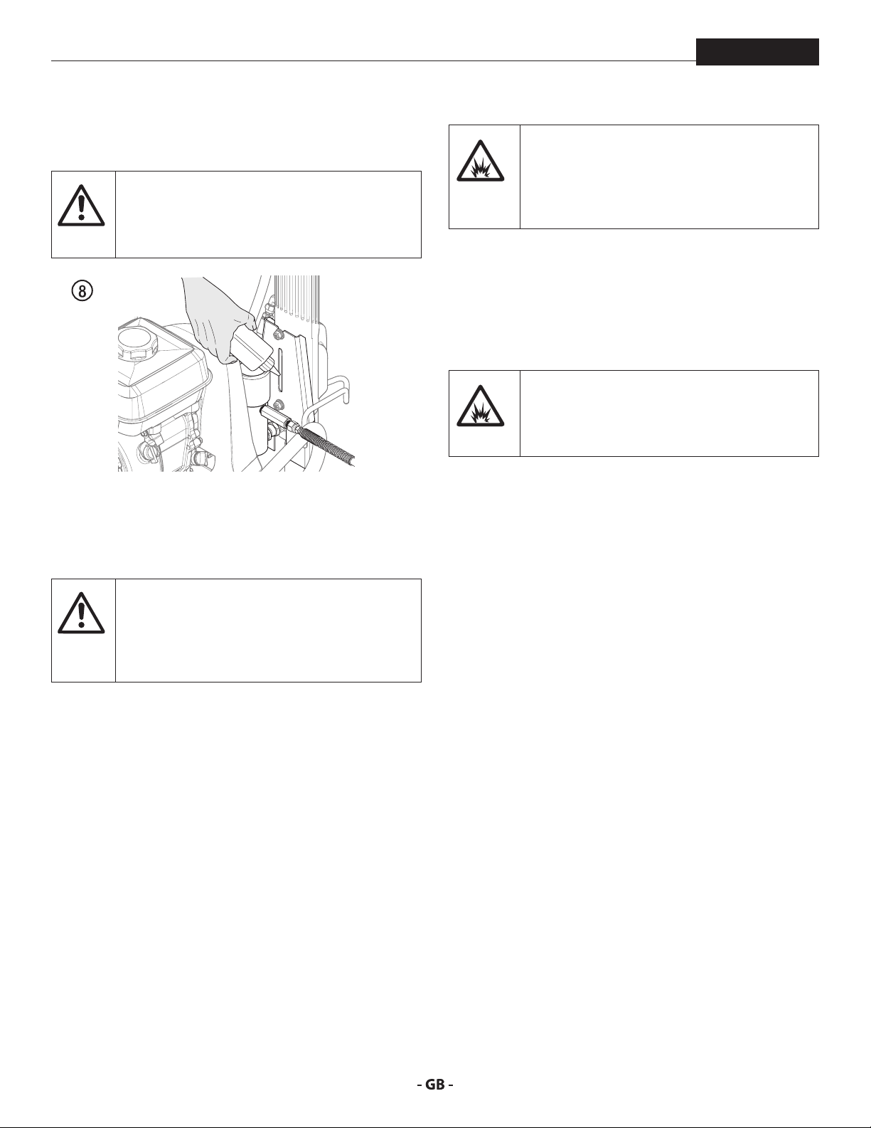
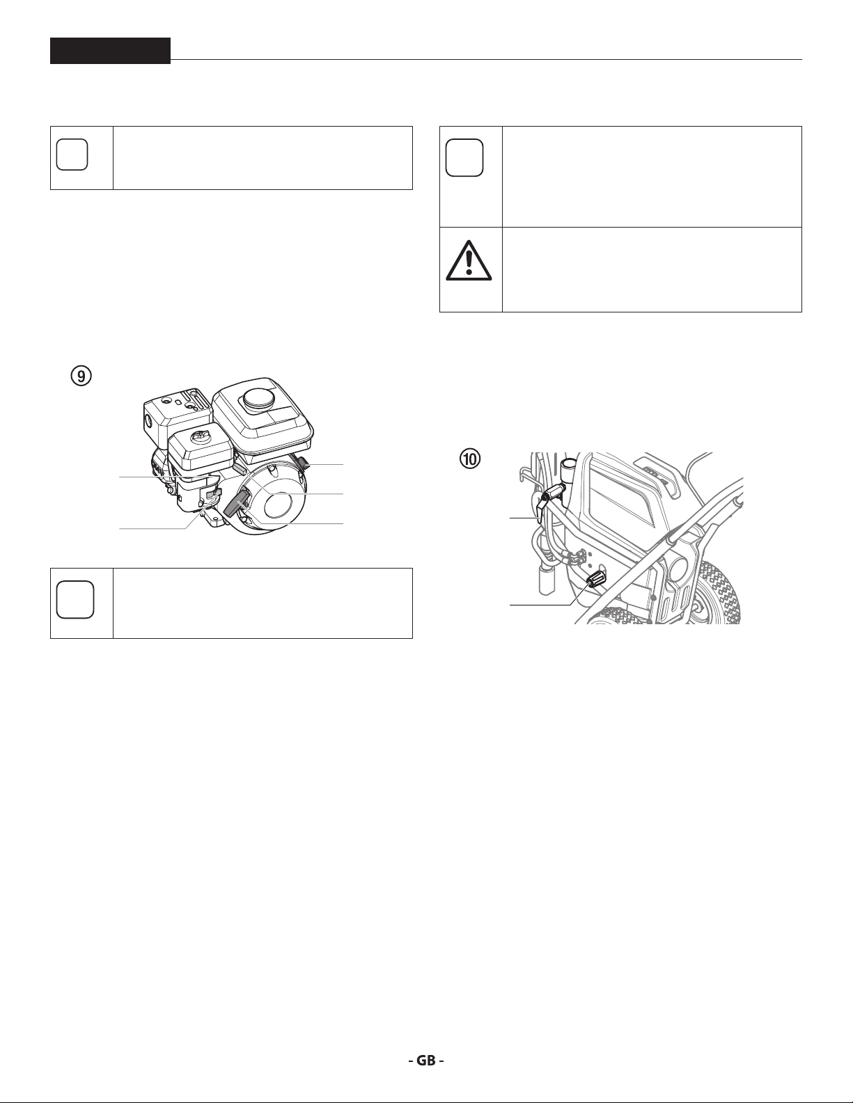
4.2 STARTING THE ENGINE GAS MODELS
Follow these instructions whenever prompted in
this manual to start the engine.
1. Move the fuel valve lever (Fig. 9, item 2) to the open
position.
2. Move the throttle lever (3) to its middle point.
3. Move the choke lever (4) to the closed position for a cold
engine or to the open position for a warm engine.
4. Turn the engine switch (1) to the ON position.
5. Pull the starter rope (5) briskly until the engine starts.
4
2
1
3
5
4.3 PREPARING A NEW SPRAYER
If this unit is new, it is shipped with test uid in
the uid section to prevent corrosion during
shipment and storage. This uid must be
thoroughly cleaned out of the system with
mineral spirits before you begin spraying.
Always keep the trigger lock on the spray gun in
the locked position while preparing the system.
tention
1. Place the siphon tube into a container of mineral spirits.
2. Place the bleed hose into a metal waste container.
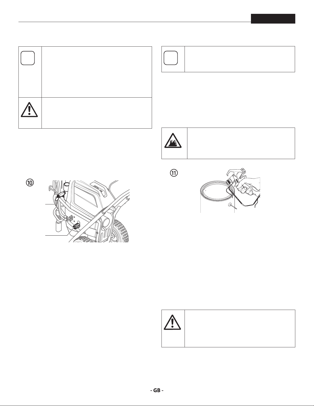
3. Turn the pressure control knob fully counterclockwise to
4. Open the bleed valve (2) by turning it fully counterclockwise.
Refer to the spray gun instruction manual for
trigger lock instructions.
its lowest pressure setting (Fig. 10, item 1).
2
If choke lever (4) was moved to closed position to
start the engine, it must be opened again once
the engine is running.
1
5. Start the engine or turn on the electric motor:
a. To start the gas engine, follow the steps in section 4.2
b. To start the electric motor, push and hold the ON/OFF
switch in the ON position until the electric motor is at full
speed, then release the switch.
6. Turn the pressure control knob (g. 10, item 1) clockwise
approximately 1/3 of the way to increase pressure until
the sprayer cycles evenly and solvent ows freely from the
bleed hose.
7. Allow the sprayer to run for 15–30 seconds to ush the
test uid out through the bleed hose and into the waste
container.
8. Turn o the sprayer.
a. To turn o the gas engine,
• set the pressure to minimum by turning the pressure
control knob fully counterclockwise,
• move the throttle lever to the slow position, and
• turn the engine switch to the OFF position.
b. To turn o the electric motor,
• set the pressure to minimum by turning the pressure
control knob fully counterclockwise,
• move the ON/OFF switch to the OFF position.
15
Page 16
operation
i
At
i
4.4 PREPARING TO PAINT
PowrBeast
Before painting, it is important to make sure that
the uid in the system is compatible with the
paint that is going to be used.
Incompatible uids and paint may cause the
valves to become stuck closed, which would
require disassembly and cleaning of the sprayer’s
uid section.
Always keep the trigger lock on the spray gun in
the locked position while preparing the system.
tention
1. Place the siphon tube into a container of mineral spirits.
2. Place the bleed hose into a metal waste container.
3. Turn the pressure control knob fully counterclockwise to
4. Open the bleed valve (2) by turning it fully counterclockwise.
Refer to the spray gun instruction manual for
trigger lock instructions.
its lowest pressure setting (Fig. 10, item 1).
Make sure that the spray gun does not have a tip
or tip guard installed.
9. Close the bleed valve by turning it fully clockwise.
10. Start the engine or turn on the electric motor.
11. Turn the pressure control knob clockwise approximately
1/3 of the way down to increase pressure.
12. Unlock the gun by turning the gun trigger lock to the
unlocked position.
Ground/Earth the gun by holding it against
the edge of the metal container while ushing.
Failure to do so may lead to a static electric
discharge, which may cause a re.
2
13. Trigger the gun into the metal waste container until the
old solvent is gone and fresh solvent is coming out of the
1
5. Start the engine or turn on the electric motor:
a. To start the gas engine, follow the steps in section 4.2
b. To start the electric motor, push and hold the ON/OFF
switch in the ON position until the electric motor is at full
speed, then release the switch.
6. Turn the pressure control knob (Fig. 10, item 1) clockwise
approximately 1/3 of the way to increase pressure until
the sprayer cycles evenly and solvent ows freely from the
bleed hose.
7. Allow the sprayer to run for 15–30 seconds to ush the
test uid out through the bleed hose and into the waste
container.
8. Turn o the sprayer.
a. To turn o the gas engine,
• set the pressure to minimum by turning the pressure
control knob fully counterclockwise,
• move the throttle lever to the slow position, and
• turn the engine switch to the OFF position.
b. To turn o the electric motor,
• set the pressure to minimum by turning the pressure
control knob fully counterclockwise,
• move the ON/OFF switch to the OFF position.
gun.
14. Lock the gun by turning the gun trigger lock to the locked
position (refer to spray gun manual).
15. Set down the gun and increase the pressure by turning
the pressure control knob slowly clockwise to its highest
setting.
16. Check the entire system for leaks. If leaks occur, turn the
sprayer o and follow the “Pressure Relief Procedure” in
this manual before tightening any ttings or hoses.
17. Follow the “Pressure Relief Procedure” (section 4.6) in this
manual before changing from solvent to paint.
Be sure to follow the Pressure Relief Procedure
when shutting the unit down for any purpose,
including servicing or adjusting any part of the
spray system, changing or cleaning spray nozzles,
or preparing for cleanup.
16
Page 17
operation
i
PowrBeast
4.5 PAINTING
1. Place the siphon hose into a container of paint.
2. Place the bleed hose into a metal waste container.
3. Turn the pressure control knob fully counterclockwise to
its lowest pressure setting (Fig. 10, item 1).
4. Open the bleed valve (2) by turning it fully counterclockwise.
5. Start the engine or turn on the electric motor:
a. To start the gas engine, follow the steps in section 4.2
b. To start the electric motor, push and hold the ON/OFF
switch in the ON position until the electric motor is at full
speed, then release the switch.
6. Turn the pressure control knob (Fig. 10, item 1) clockwise
approximately 1/3 of the way down to increase pressure
until the sprayer cycles evenly and solvent ows freely
from the bleed hose.
7. Turn o the sprayer.
a. To turn o the gas engine,
• set the pressure to minimum by turning the pressure
control knob fully counterclockwise,
• move the throttle lever to the slow position, and
• turn the engine switch to the OFF position.
b. To turn o the electric motor,
• set the pressure to minimum by turning the pressure
control knob fully counterclockwise,
• move the ON/OFF switch to the OFF position.
8. Remove the bleed hose from the waste container and
place it into the container of paint.
9. Close the bleed valve by turning it fully clockwise.
10. Start the engine or turn on the electric motor.
11. Turn the pressure control knob clockwise approximately
1/3 of the way down to increase pressure.
12. Unlock the gun by turning the gun trigger lock to the
unlocked position.
Ground/Earth the gun by holding it against
the edge of the metal container while ushing.
Failure to do so may lead to a static electric
discharge, which may cause a re.
13. Trigger the gun into the metal waste container until all
air and solvent is ushed from the spray hose and paint is
owing freely from the gun.
14. Lock the gun by turning the gun trigger lock to the locked
position.
15. Turn o the sprayer.
16. Attach tip guard and tip to the gun as instructed by the tip
guard or tip manuals.
17. Start the engine or turn on the electric motor.
18. Increase the pressure by turning the pressure control knob
slowly clockwise and test the spray pattern on a piece of
cardboard. Adjust the pressure control knob until the
spray from the gun is completely atomized.
4.6 PRESSURE RELIEF PROCEDURE
1. Lock the spray gun by turning the gun trigger lock to the
locked position.
2. Turn o the sprayer.
a. To turn o the gas engine,
• set the pressure to minimum by turning the pressure
• move the throttle lever to the slow position, and
• turn the engine switch to the OFF position.
b. To turn o the electric motor,
• set the pressure to minimum by turning the pressure
• move the ON/OFF switch to the OFF position.
3. Unlock the gun by turning the gun trigger lock to the
unlocked position (refer to spray gun manual).
4. Hold the metal part of the gun rmly to the side of a metal
waste container to ground/earth the gun and avoid a build
up of static electricity.
5. Trigger the gun to remove any pressure that may still be
in the hose.
6. Lock the gun by turning the gun trigger lock to the locked
position (refer to spray gun manual).
7. Place the bleed hose into the metal waste container.
8. Open the bleed valve by turning it fully counterclockwise.
POSSIBLE INJECTION HAZARD. Do not spray
without the tip guard in place. Never trigger the
gun unless the tip is in either the spray or the
unclog position. Always engage the gun trigger
lock before removing, replacing or cleaning tip.
Turning the pressure up higher than needed to
atomize the paint will cause premature tip wear
and additional overspray.
Be sure to follow the Pressure Relief Procedure
when shutting the unit down for any purpose,
including servicing or adjusting any part of the
spray system, changing or cleaning spray nozzles,
or preparing for cleanup.
control knob fully counterclockwise,
control knob fully counterclockwise,
17
Page 18
spraying
i
i
5 SPRAYING
PowrBeast
Injection hazard. Do not spray without the tip
guard in place. NEVER trigger the gun unless
the tip is completely turned to either the spray
or the unclog position. ALWAYS engage the
gun trigger lock before removing, replacing or
cleaning tip.
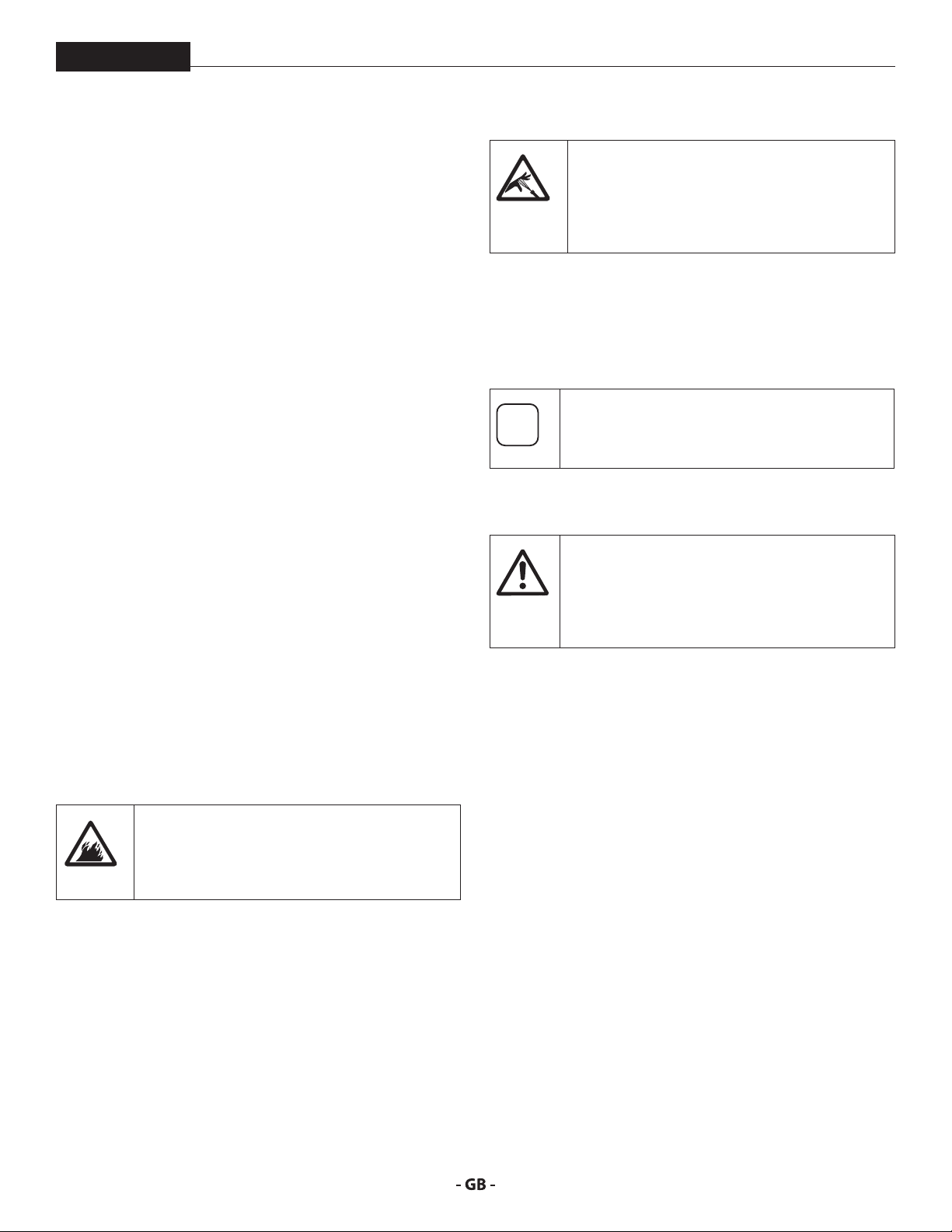
A) The key to a good paint job is an even coating over the
entire surface. Keep your arm moving at a constant speed
and keep the spray gun at a constant distance from the
surface. The best spraying distance is 10-12 inches (25 to
30 cm) between the spray tip and the surface.
A
25 - 30 cm
C
25 - 30 cm25 - 30 cm
If very sharp edges result or if there are streaks in
the spray jet – increase the operating pressure or
dilute the coating material.
5.1 CLEANING A CLOGGED TIP
If the spray pattern becomes distorted or stops
completely while pulling the trigger, perform the
steps below.
B) Keep the spray gun at right angles to the surface. This
means moving your entire arm back and forth rather than
just exing your wrist.
Keep the spray gun perpendicular to the surface,
otherwise one end of the pattern will be thicker than the
other.
B
C) Trigger gun after starting the stroke. Release the trigger
before ending the stroke. The spray gun should be
moving when the trigger is pulled and released. Overlap
each stroke by about 30%. This will ensure an even
coating.
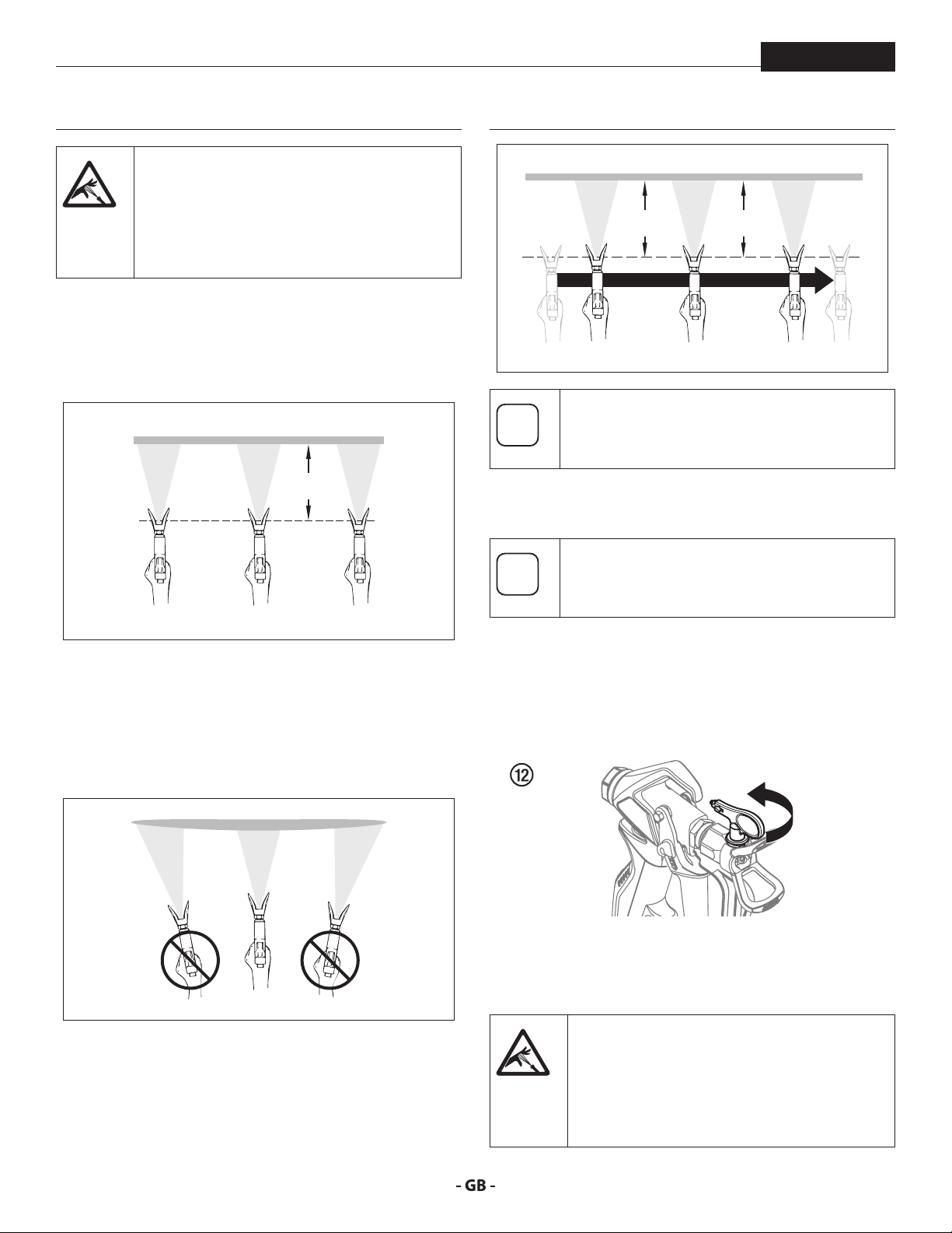
1. Turn the relief valve to PRIME (k circulation).
2. If the tip clogs, rotate the tip handle 180° until the arrow on
the handle is facing the opposite of the spray direction and
the handle clicks in the reverse position (Fig. 12).
3. Turn the relief valve to SPRAY (p spray).
4. Trigger the gun once so that the pressure can blow the
clog out. NEVER use the tip in the reverse position for
more than ONE trigger pull at a time. This procedure can
be repeated until the tip is free of clogging.
The ow from the spray tip is at very high
pressure. Contact with any body part may be
dangerous. Do not place nger on gun outlet.
Do not point the gun at any person. Never
operate the spray gun without the proper tip
guard.
18
Page 19
spraying
i
i
At
i
i
i
i
i
PowrBeast
5.2 INTERRUPTION OF WORK
Follow these steps if stopping work for up to 20
hours. Only follow these steps if you used latex or water-based spray materials.
If you are just simply swapping out material
containers, turn the pressure control knob fully
counterclockwise to minimum prior to changing
the material container.
Turn pressure control knob clockwise to previous
position when ready to resume spraying.
1. Follow the “Pressure Relief Procedure” found in the
Operation section of this manual, section 4.6.
2. Place the spray gun in a plastic bag, or drop it into a bucket
of water.
3. Leave the suction tube and return hose immersed in
the coating material or immerse it into a corresponding
cleaning agent.
4. Cover the coating material with plastic and place unit in a
cool, shaded spot to keep material from drying out.
If fast-drying or two-component coating material
is used, ensure that the unit is rinsed with a
tention
suitable cleaning agent within the processing
time.
When ready to being spraying again, remove the
plastic from the material container and restart
the sprayer by following the steps in section 4.5.
5.3 HANDLING THE HIGHPRESSURE HOSE
The unit is equipped with a high-pressure hose
specially suited for airless pumps.
Danger of injury through leaking high-pressure
hose. Replace any damaged high-pressure hose
immediately.
Never repair damaged high-pressure hoses
yourself!
The high-pressure hose is to be handled with care. Avoid sharp
bends and folds: the smallest bending radius is about 8” (20 cm).
Do not drive over the high-pressure hose. Protect against sharp
objects and edges.
Never pull on the high-pressure hose to move the device.
Make sure that the high-pressure hose cannot twist. This can
be avoided by using a Titan spray gun with a swivel joint and
hose system.
When using the high-pressure hose while
working on scaolding, it is best to always guide
the hose along the outside of the scaolding.
The risk of damage rises with the age of the
high-pressure hose. Titan recommends replacing
high-pressure hoses after 6 years.
Use only Titan original-high-pressure hoses
in order to ensure functionality, safety and
durability.
19
Page 20
cleanup
At
At
i
At
Attention
6 CLEANUP
The sprayer, hose, and gun should be cleaned
thoroughly after daily use. Failure to do so
tention
permits material to build up, seriously aecting
the performance of the unit.
PowrBeast
9. Switch the unit OFF (turn the engine switch OFF).
10. Close the bleed valve by rotating the bleed valve handle
fully clockwise.
11. Start the engine or turn on the electric motor.
Always spray at minimum pressure with the gun
nozzle tip removed when using mineral spirits
or any other solvent to clean the sprayer, hose,
or gun. Static electricity buildup may result in a
re or explosion in the presence of ammable
vapors.
6.1 SPECIAL CLEANUP INSTRUCTIONS FOR USE
WITH FLAMMABLE SOLVENTS
• Always ush spray gun preferably outside and at least one
hose length from spray pump.
• If collecting ushed solvents in a one gallon metal
container, place it into an empty ve gallon container, then
ush solvents.
• Area must be free of ammable vapors.
• Follow all cleanup instructions.
6.2 CLEANING THE SPRAYER
1. Follow the “Pressure Relief Procedure” found in the
Operation section of this manual, section 4.6.
2. Remove the gun tip and tip guard and clean with a brush
using the appropriate solvent.
3. Place the siphon tube into a container of the appropriate
solvent.
Earth the gun by holding it against the edge
of the metal container while ushing. Failure
to do so may lead to a static electric discharge,
which may cause a re.
12. Trigger the gun into the metal waste container until the
paint is ushed out of the hose and solvent is coming out
of the gun.
13. Continue to trigger the spray gun into the waste container
until the solvent coming out of the gun is clean.
For long-term or cold weather storage, pump
mineral sprits through the entire system.
14. Follow the “Pressure Relief Procedure” found in the
Operation section of this manual.
15. Store the sprayer in a clean, dry area.
Do not store the sprayer under pressure.
tention
6.3 CLEANING THE OUTSIDE OF THE UNIT
Use only compatible solvents when cleaning
out oil based enamels, lacquers, coal tar, and
tention
4. Place the bleed hose into a metal waste container.
5. Set the pressure to minimum by turning the pressure
6. Open the bleed valve by rotating the bleed valve handle
7. Start the engine or turn on the electric motor.
8. Allow the solvent to circulate through the sprayer and
epoxies. Check with the uid manufacturer for
the recommended solvent.
control knob fully counterclockwise.
fully counterclockwise.
ush the paint out of the bleed hose into the metal waste
container.
20
Electric models - Make sure the power cord is
unplugged to prevent electric shock.
Danger of short circult through penetrating
water!
Never spray down the unit with high-pressure
water or high-pressure steam cleaners.
Do not put the high-pressure hose into solvents.
Use only a wet cloth to wipe down the outside of
the hose.
Wipe down unit externally with a cloth which has been
immersed in a suitable cleaning agent.
Page 21
cleanup
i
i
PowrBeast
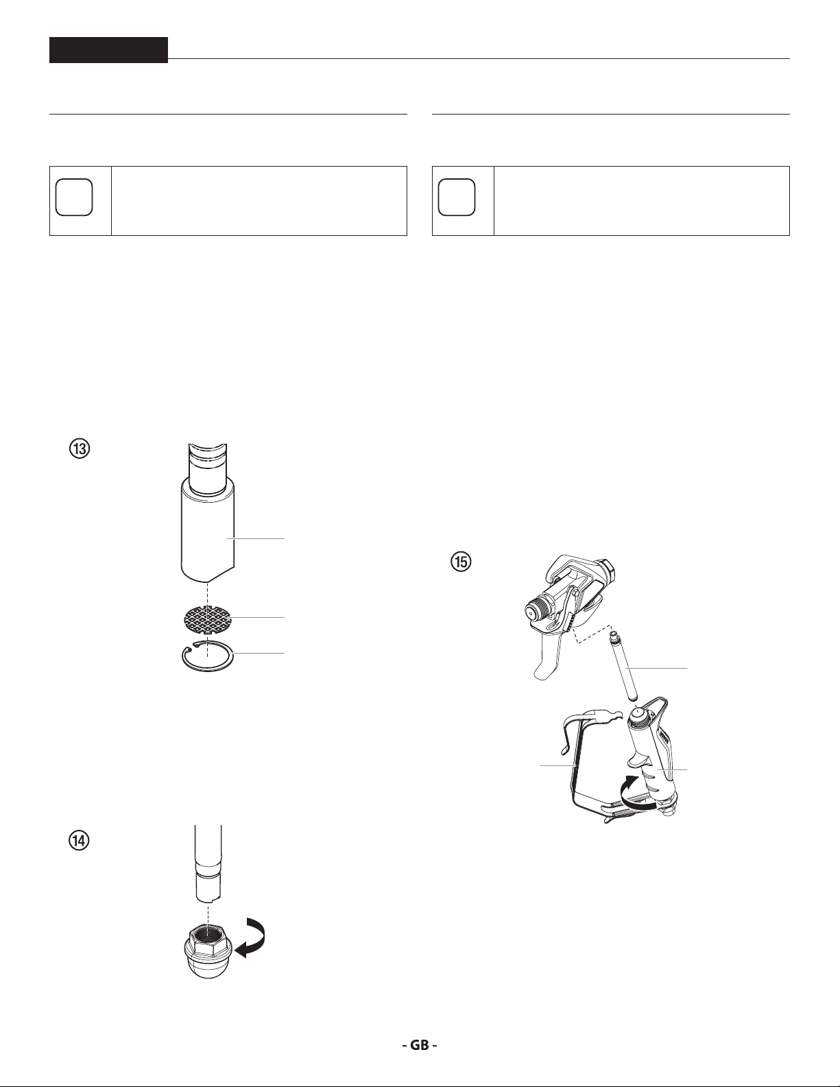
6.4 CLEANING THE FILTER SCREEN
A clean lter screen always guarantees maximum
feed quantity, constant spraying pressure and
problem-free functioning of the unit.
SUBMERSIBLE SUCTION SYSTEM
1. The lter screen will clog and must be cleaned at least
once a day.
2. Remove the retaining ring (Fig. 13, item 1) from the foot
valve housing (2).
3. Remove the inlet screen (3) from the foot valve housing
(2).
4. Clean thoroughly with the appropriate solvent.
2
6.5 CLEANING AIRLESS SPRAY GUN
Clean the spray gun after each use.
1. Rinse airless spray gun with an appropriate cleaning agent.
2. Clean tip thoroughly with appropriate cleaning agent so
that no coating material residue remains.
3. Thoroughly clean the outside of the airless spray gun.
INTAKE FILTER IN AIRLESS SPRAY GUN FIG. 15
1. Unclip the top of the trigger guard (1) from the gun head.
2. Using the bottom of the trigger guard as a wrench, loosen
and remove the handle assembly (2) from the gun head.
3. Pull the old lter (3) out of the gun head. Clean or replace.
4. Slide the new lter, tapered end rst, into the gun head.
5. Thread the handle assembly into the gun head. Tighten
with the trigger wrench.
6. Snap the trigger guard back onto the gun head.
3
1
STANDARD SUCTION SYSTEM
1. Screw o the lter (Fig. 14) from suction tube.
2. Clean or replace the lter.
Carry out cleaning with a hard brush and an appropriate
cleaning agent.
3
1
2
21
Page 22
maintenance
i
i
i
7 MAINTENANCE
PowrBeast
Before proceeding, follow the Pressure Relief
Procedure outlined previously in this manual.
Additionally, follow all other warnings to reduce
the risk of an injection injury, injury from moving
parts or electric shock. Always unplug the sprayer
before servicing!
7.1 DAILY MAINTENANCE
Two daily procedures are required for routine operator
maintenance on this sprayer:
A. Lubricating the upper packings (section 7.2).
B. Cleaning the lter screen (section 6.4).
7.2 LUBRICATING THE UPPER PACKINGS
1. Clean out the paint that has seeped past the upper
packings into the packing oil reservoir (g. 16, item 1)
above the uid section.
2. Fill the packing oil reservoir 1/2 full with Piston Lube (P/N
314-480) supplied by the factory. This will extend packing
life.
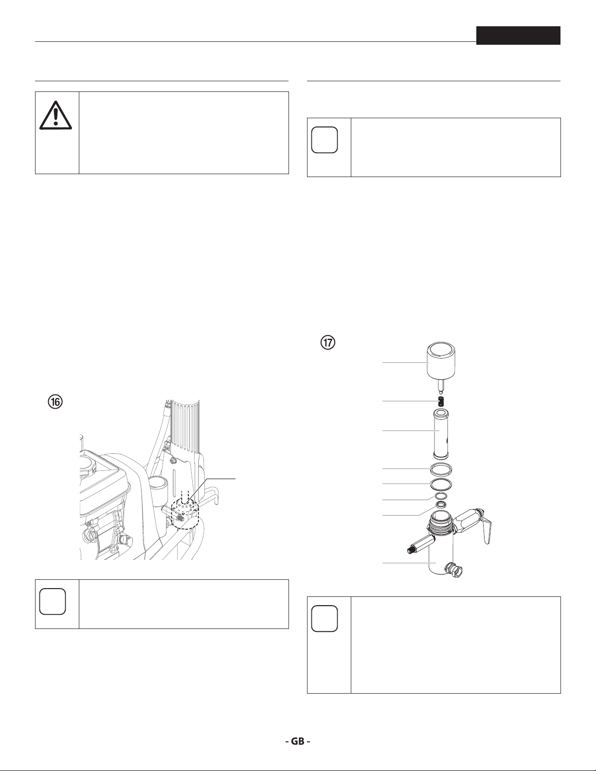
7.3 MAINTAINING THE FILTER ASSEMBLY
Clean the lter regularly. Dirty or clogged lters
can greatly reduce ltering ability and cause
a number of system problems including poor
spray patterns, clogged spray tips, etc.
CLEANING FIG. 17
To clean the lter, perform the following procedure.
1. Follow the “Pressure Relief Procedure” found in the
Operation section of this manual.
2. Remove the lter cap assembly (1) and spring (2).
3. Pull the lter element with ball straight (3) out of the lter
body (4).
4. Clean inside the lter body, lter element with ball, and
lter cap assembly using the appropriate solvent.
1
1
Do not over-ll the reservoir so that it overows
and drips into the paint.
2
3
7
8
5
6
4
Use care in handling parts as dirt, debris,
scratches, or nicks may prevent o-rings or gaskets
from sealing.
This lter element lters from the inside out. Be
sure to clean the lter element thoroughly on the
inside. Soak in solvent to loosen hardened paint
or replace.
22
Page 23
maintenance
i
i
i
At
i
i
PowrBeast
INSPECTION FIG. 17
Inspect all parts of the lter assembly before reassembly.
1. Inspect the ball inside the lter element. If the ball has
pressure cuts or scratches, replace the lter element.
a. If the ball is cut, remove the PTFE o-ring (5) using an
o-ring pick and remove the carbide seat (6).
b. Check the seat for nicks or grooves. If the seat is
damaged, replace.
Removal of the PTFE o-ring will damage the
o-ring and require replacement.
2. Remove the spring (2) from the spring guide on the lter
cap.
a. Measure the length of the spring uncompressed. If it
measures less than 3/4” from end to end, replace.
b. Push the spring back onto the spring guide until it
“snaps” back into position.
3. Inspect the two PTFE gaskets (7,8) and the PTFE o-ring (5)
for deformity, nicks, or cuts. Replace, if needed.
The PTFE gaskets, PTFE o-ring, and spring are
packaged in Filter Service Kit P/N 930-050.
7.4 MAINTAINING THE HYDRAULIC SYSTEM
Use of Titan’s Coolo™ Hydraulic Fluid is
mandatory in the PowrTwin Plus DI hydraulic
tention
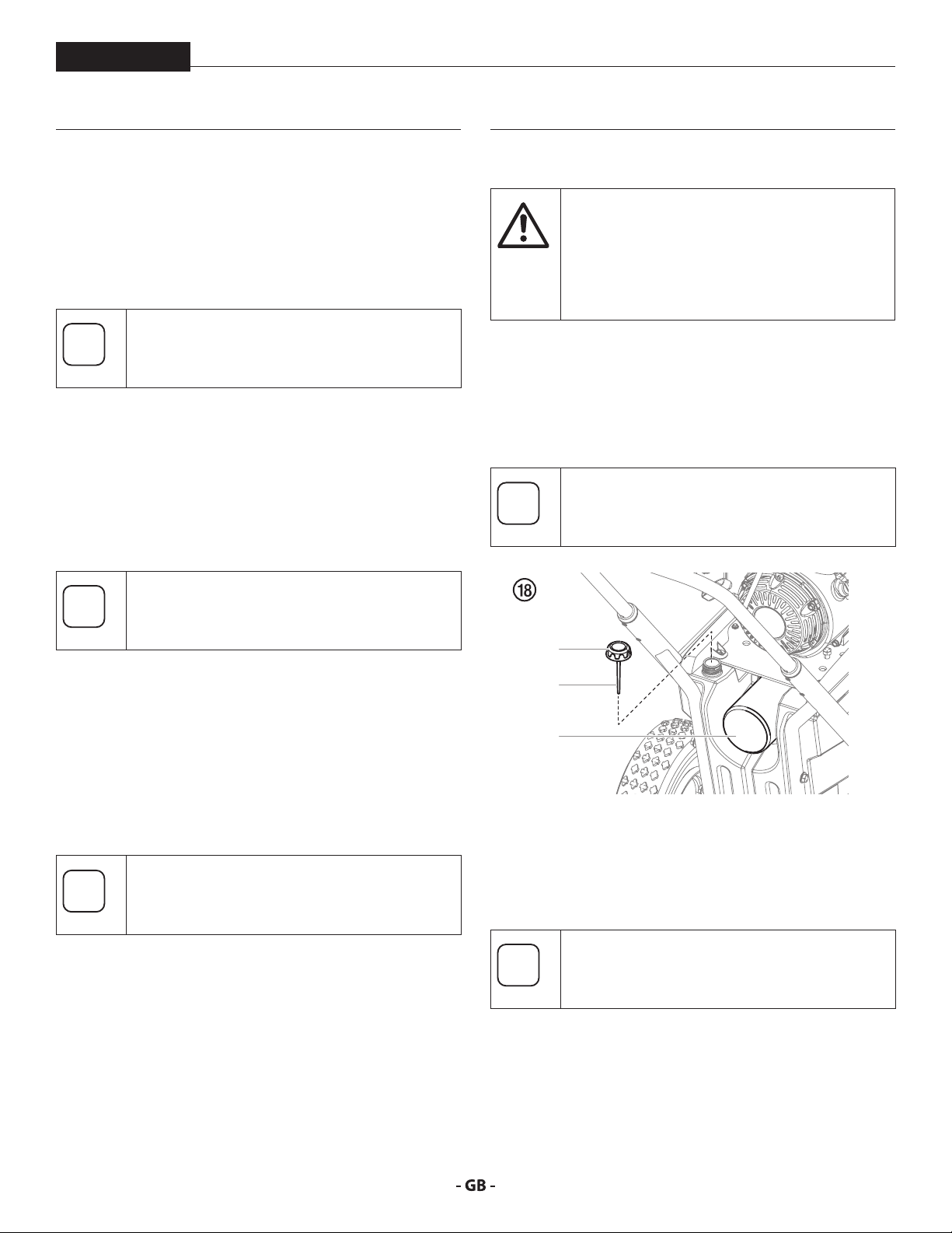
1. Check the hydraulic uid daily. The hydraulic uid level
system. Do not use any other hydraulic uid.
Use of any other hydraulic uid may seriously
damage the hydraulic system and will void the
warranty.
should be touching the bottom of the dipstick (1). If it is
dry, add only Titan Coolo™ Hydraulic Fluid (P/N 430-361).
Never add or change hydraulic uid except in a clean,
dust-free area. Contamination of the hydraulic uid will
shorten hydraulic pump life and may void warranty.
Make sure the unit is on a at, level surface when
checking the hydraulic uid level.
REASSEMBLY FIG. 17
After cleaning and inspecting all parts, reassemble the lter.
1. Place the carbide seat (6) into the lter body (4). Make sure
the beveled side of the seat is facing up.
2. Place the PTFE o-ring (5) into the groove on the outer
diameter of the carbide seat (6).
3. Place the lter element with ball (3) into the lter body (4).
The top and bottom of the lter element with
ball are identical.
4. Push the spring (2) back onto the spring guide of the lter
cap (1) until it “snaps” back into position, if not already
done.
5. Place the thin PTFE gasket (8) onto the step at the top of
the lter body (4).
6. Place the thick PTFE gasket (7) onto the top of the thin
gasket (8).
7. Tighten the lter cap assembly (1) onto the lter body (4).
2
1
3
2. Change the hydraulic uid every twelve months. Drain the
old uid from the tank and ll with 6.25 quarts of hydraulic
uid. Start the sprayer at just enough pressure to operate
the uid section. Run the sprayer at this low pressure for at
least 5 minutes. This removes air from the system. Check
the uid level after this procedure. Do not over-ll.
When replacing the hydraulic lter (3) during a
uid change, it may be necessary to add up to
one additional quart of hydraulic uid.
3. The hydraulic system has an external, replaceable hydraulic
lter. Change the lter every twelve months.
4. The hydraulic pump should not be serviced in the eld.
If service on the hydraulic pump is required, it must be
returned to an authorized Titan Service Center.
23
Page 24

maintenance
At
i
PowrBeast
7.5 MAINTAINING THE FLUID SECTION
If the sprayer is going to be out of service for an extended period
of time, it is recommended that following cleanup, a kerosene
and oil mixture be introduced as a preservative. Packings may
tend to dry out from lack of use. This is particularly true of the
upper packing set for which upper packing lubricant Piston
Lube (P/N 314-480) is recommended in normal usage.
If the sprayer has been out of service for an extended period
of time, it may be necessary to prime the pump with solvent.
It is extremely important that the threads on the siphon hose
coupling are properly sealed. Any air leakage will produce
erratic operation of the sprayer and may damage the system.
The up and the down strokes should be approximately equal
in time (one should not be faster than the other). A fast up or
down stroke may indicate air in the system or malfunctioning
valve or seats (see the Troubleshooting section).
7.6 HIGHPRESSURE HOSE
Inspect the high-pressure hose visually for any notches or
bulges, in particular at the transition in the ttings. It must be
possible to turn the union nuts freely. A conductivity of less
than 1 MΩ must exist across the entire length.
Have all the electric tests carried by an Authorized
Titan Service Center.
tention
The risk of damage rises with the age of the highpressure hose.
Titan recommends replacing high-pressure
hoses after 6 years.
24
Page 25

maintenance
PowrBeast
7.7 BASIC ENGINE MAINTENANCE GAS ENGINE
• For detailed engine maintenance and technical
specications refer to the separate gasoline engine manual.
• All service to the engine should be performed by a dealer
authorized by the engine manufacturer.
• Use a premium quality motor oil. 10W30 is recommended
for general all temperature use. Other viscosities may be
required in other climates.
• Use only a (NGK) BP6ES or BPR6E spark plug. Gap the
plug to 0.028 to 0.031 In. (0.7 to 0.8 mm) Always use a
spark plug wrench.
DAILY
1. Check engine oil level, and ll as necessary.
2. Check gasoline level, and ll as necessary.
Always follow the fueling procedure outlined
earlier in this manual.
FIRST 20 HOURS
• Change engine oil.
ENGINE OPERATION AND SERVICE
• Clean and oil air lter pad on gasoline engine every 25
hours or once weekly. Do not permit the air intake screen
around the y wheel of the gas engine to load up with paint
or trash. Clean it regularly. The service life and eciency
of the gas engine model depends upon keeping the
gasoline engine running properly. Change the oil in the
engine every 100 hours. Failure to observe this may result
in engine overheating. Consult the engine manufacturer’s
service manual provided.
• To conserve fuel, service life, and eciency of the sprayer,
always operate the gasoline engine at the lowest RPM at
which it runs smoothly without laboring and delivers the
amount required for the particular painting operation.
Higher RPM does not produce higher working pressure.
The gasoline engine is connected to the hydraulic pump
by a pulley combination designed to produce full paint
delivery at maximum RPM.
• The warranty on gasoline engines or electric motors is
limited to the original manufacturer.
EVERY 100 HOURS
• Change engine oil.
• Clean the sediment cup.
• Clean and re-gap the spark plug.
• Clean the spark arrestor.
WEEKLY
• Remove the air lter cover and clean the element. In
very dusty environments, check the lter daily. Replace
the element as needed. Replacement elements can be
purchased from your local engine manufacturer dealer.
25
Page 26
maintenance
At
i
i
7.8 SERVICING THE HYDRAULIC MOTOR
PowrBeast
Servicing of the hydraulic motor should be carried
out in a clean, dust free area only. Any dust or
tention
1. Turn the pressure control knob all the way counterclockwise
2. With the uid section submersed in a bucket of water, start
3. Turn the pressure control knob clockwise 1-2 full turns.
4. Once the pump is primed, turn the relief valve to SPRAY.
5. While watching the piston stroke from the window on the
6. Turn o the engine or electric motor.
7. Continue by following the steps below.
DISASSEMBLING THE HYDRAULIC MOTOR
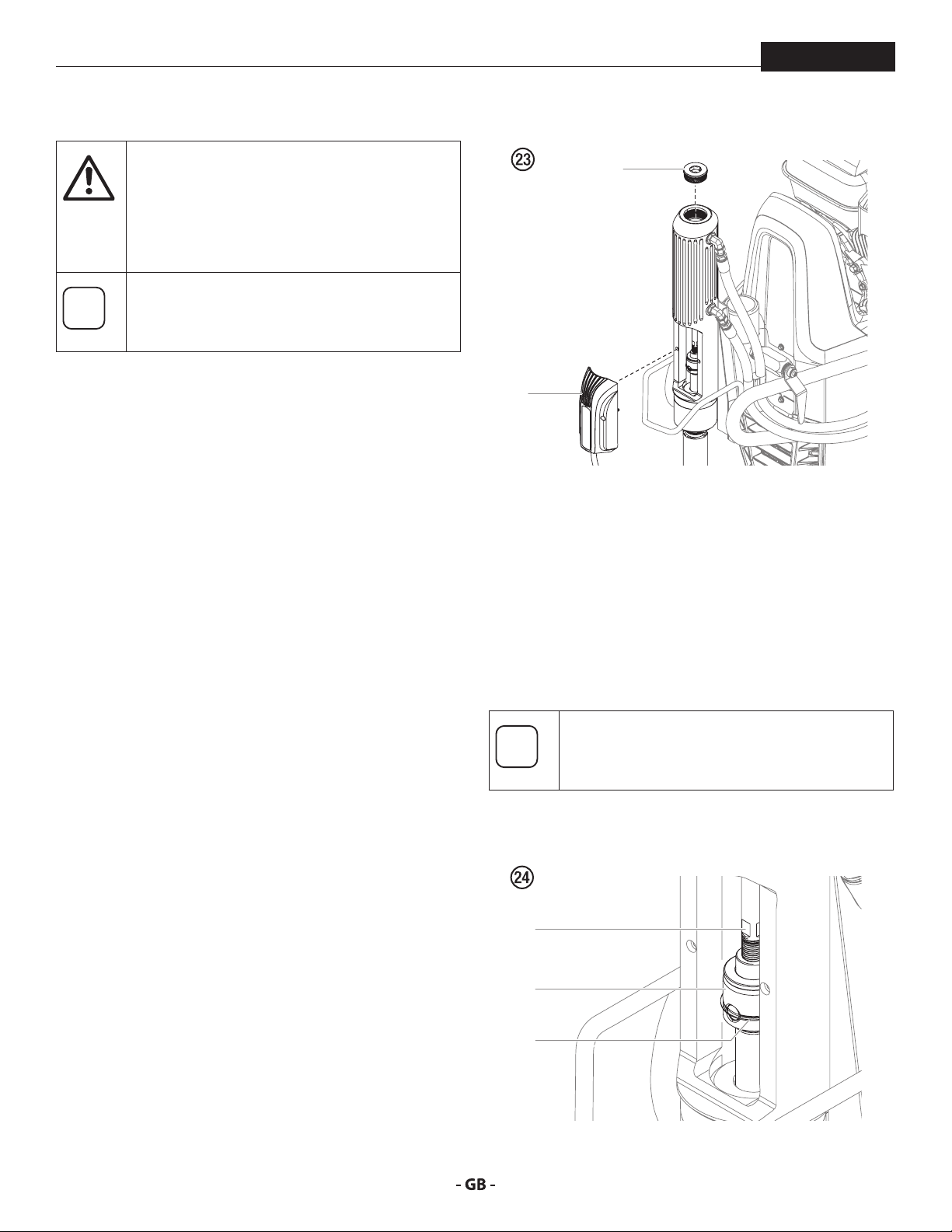
1. Using a hex wrench, loosen the captive screws that secure
2. Remove the cylinder head plug (2) from the hydraulic
metallic particles left in the motor or entering
it on reassembly may damage the critical parts
and aect its service life and warranty. All parts
should be inspected for absolute cleanliness.
In order to service the hydraulic motor, it is
recommended that the piston be set in the
middle of its stroke. Follow the steps below.
to the lowest setting.
the engine or turn on the electric motor.
back side of the motor/pump and using the smallest tip
available (for slowest piston speed possible), spray water
back in to the bucket (or other waste container). Stop
spraying when the piston is in the desired location.
the PCB board assembly (Fig. 23, item 1) to the hydraulic
motor cylinder. Once removed, the board can hang by its
cord.
motor cylinder.
1
2
3. Using a syringe or sponge, soak up any excess hydraulic
uid in the cavity left by removing the cylinder head plug.
4. In the access area left by the removal of the PCB board
assembly, locate the ats on the bottom of the hydraulic
piston (Fig. 24, item 3). Place a wrench on the hydraulic
piston ats.
5. Slide the retaining ring (4) on the piston coupler (5) up to
clear it of the coupler holes.
6. Carefully insert a screwdriver into one of the open holes of
the piston coupler (5) to secure it.
You may need to twist the entire hydraulic piston
(4) and coupler (5) assembly slightly with the
wrench to gain access to one of the open holes.
7. Loosen the hydraulic piston (4) from the coupler (5) using
the wrench on the ats of the hydraulic piston (4).
4
5
3
26
Page 27
maintenance
i
At
i
i
PowrBeast
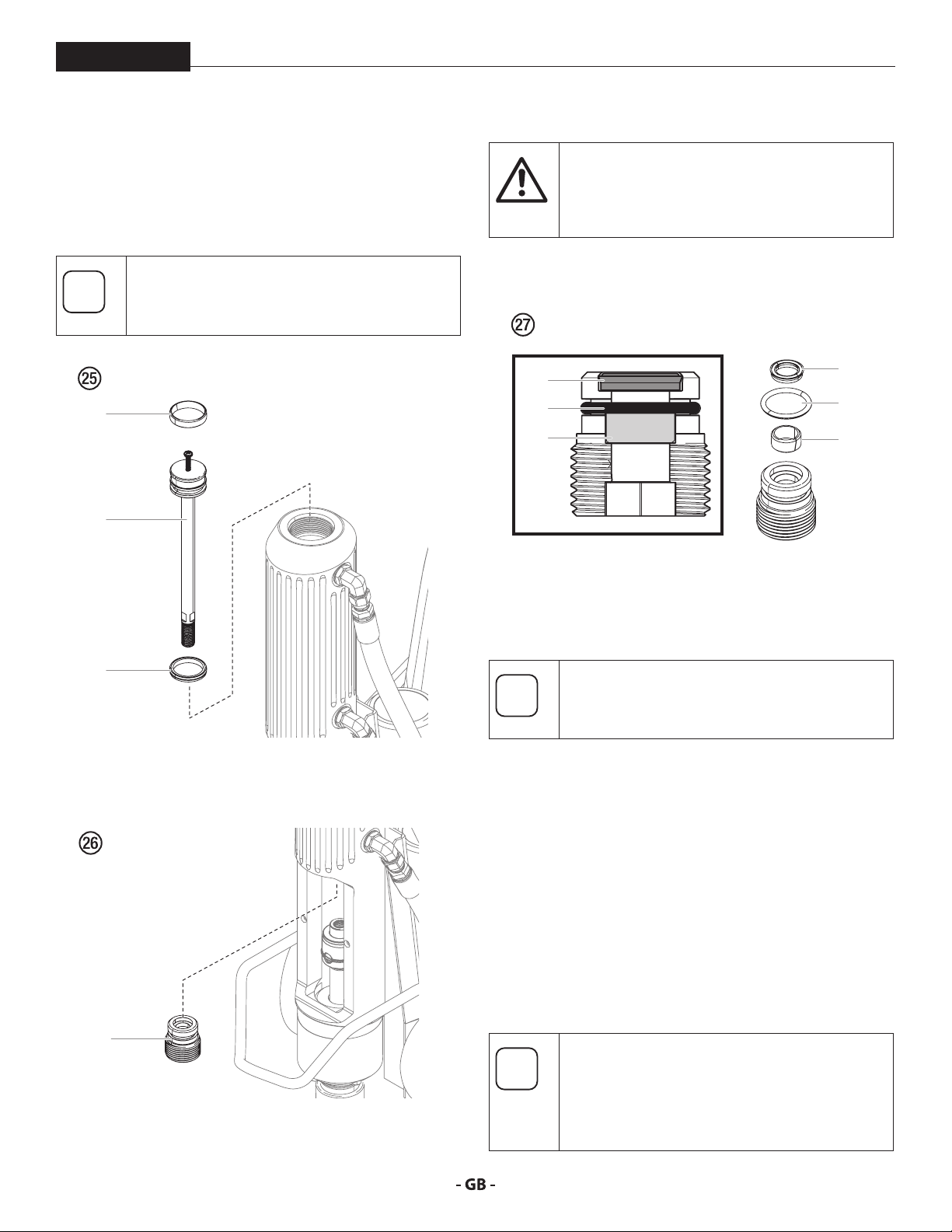
8. Lightly thread a 1/4 - 20 screw into the top of the hydraulic
piston (Fig. 25, item 4). Using the screw, pull the piston
from the top of the hydraulic motor cylinder.
9. Carefully remove the seal (6) and wear ring (7) from the
piston. Replace with new parts from the kit.
Be sure to coat the the new seal and wear ring
with hydraulic oil prior to reinstallation.
6
4
Remove these parts very carefully. Do not scratch
any metal surface of the plug assembly
tention
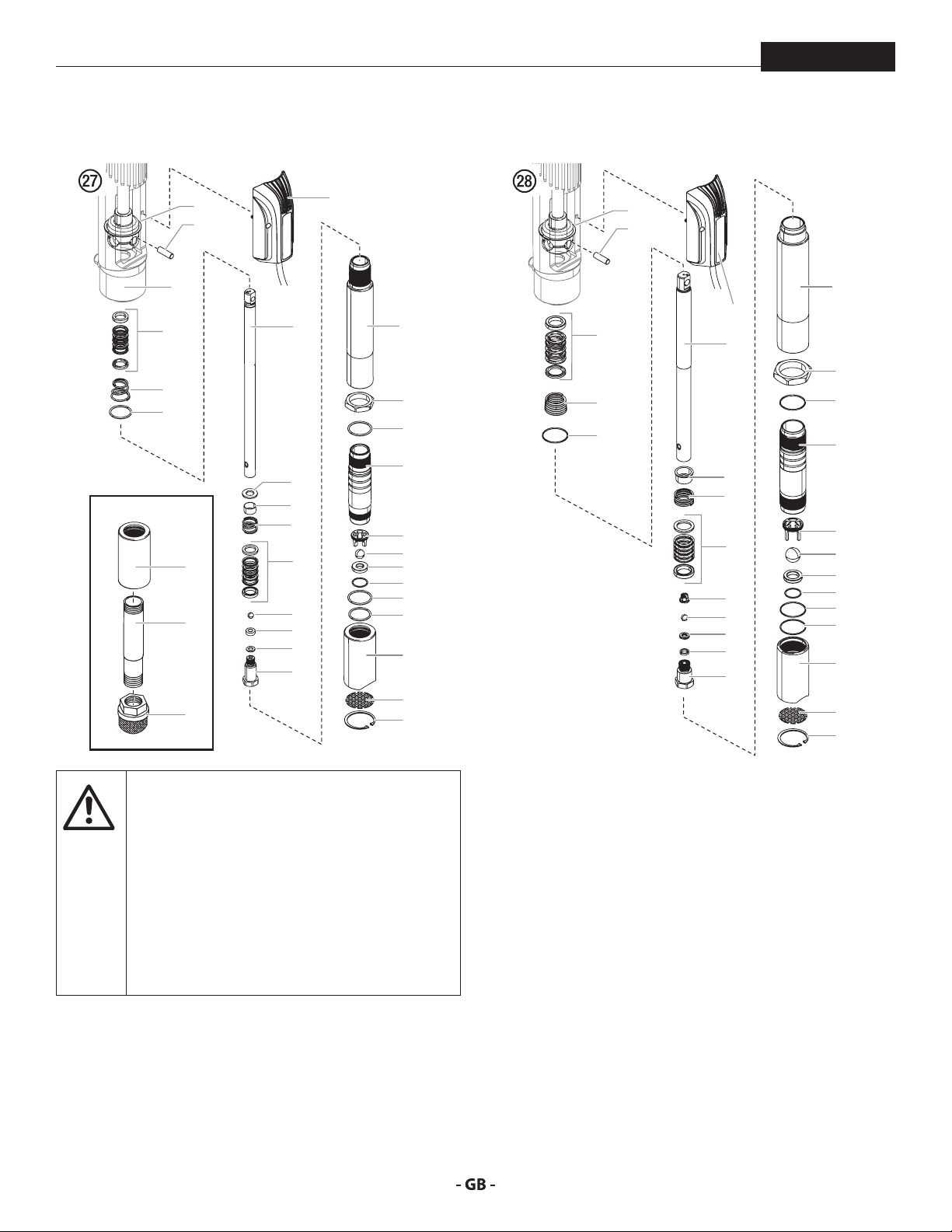
12. Soak the new parts from the kit in hydraulic oil and reinstall
back onto the plug.
11
10
9
REASSEMBLING THE HYDRAULIC MOTOR
1. Replace the plug assembly (8) into the interior of the
hydraulic motor cylinder. Tighten with the L-shaped hex
wrench.
11
10
9
7
10. Using an L-shaped hex wrench, unthread the plug
assembly (Fig. 26, item 8) from the inside of the hydraulic
motor cylinder.
8
11. Carefully remove the wear ring (Fig. 27, item 9), O-ring (10),
and cup seal with O-ring (11) from the plug.
Inspect the bottom of the hydraulic piston for
any sharp areas that could damage the piston
seal (11) during reinstallation.
2. Replace the hydraulic piston (4) back into the top of the
hydraulic motor cylinder. Using a rubber mallet, carefully
tap the piston down into the cylinder until the ats are
visible in the access area above the piston coupler (5).
3. Remove the 1/4 - 20 screw from the top of the piston
assembly.
4. Using a screwdriver in the open hole of the piston coupler
(5) and a wrench on the ats of the hydraulic piston (4),
reattach the two parts and tighten.
5. Slide the retaining ring on the coupler back in place.
6. Replace the cylinder head plug (2).
7. Replace the PCB board assembly (1).
Once this repair is complete, start the engine or
turn on the electric motor. Allow the unit to run
for a few minutes and then shut it down.
Immediately check the hydraulic oil level and
rell if needed.
27
Page 28
maintenance
At
7.9 SERVICING THE FLUID SECTION
PowrBeast
POWRBEAST 4700 / POWRBEAST 4700T
1
2
29
4a
5
3
4700
23
26
27
6
8
7
9
4b
10
11
12
13
30
14
15
31
16
17
18
19
20
21
22
23
24
25
POWRBEAST 7700 / POWRBEAST 9700
1
2
30
4a
5
3
6
8
9
4b
28
10
11
12
13
14
15
31
16
17
18
19
20
21
22
23
24
25
Use of non-Titan service parts may void warranty.
3. PowrBeast 4700 - Remove the siphon tube (26).
4. Spin the uid section removal nut (15) counterclockwise
so that it bottoms out on the threads on the cylinder (16).
5. Place a wrench on the ats of the uid section removal
nut (15). Turn the wrench counterclockwise to loosen the
entire uid section.
6. Carefully pull down the uid section to remove from the
hydraulic motor.
7. In order to service the uid section, stabilize it by securing
the ats of the uid section removal nut (15) in a vise.
tention
Ask for original parts made by Titan for best
services. This pump should receive a routine
servicing after approximately 1,000 hours of use.
Earlier servicing is required if there is excessive
leakage from the top packing or if pump strokes
become faster on one stroke or the other.
The use of Titan Piston Lube (P/N 314-480) is
recommended as an upper packing lubricant.
Do not substitute oil, water, or solvent for an
upper packing lubricant.
8. Unthread the foot valve housing (23) with a strap wrench.
9. Remove upper packing spring (5), and upper packing set
DISASSEMBLING THE FLUID SECTION
1. Using a hex wrench, loosen the captive screws that secure
the PCB board assembly (Fig. 27, item 30) to the hydraulic
motor cylinder. Once removed, the board can hang by its
cord.
2. Slide the retainer ring (1) up with a small screwdriver, then
(4a) from the motor/pump block.
10. Place a wrench on the ats on top of the displacement rod
(6). Using a second wrench, loosen and remove the outlet
valve housing (13) from the displacement rod (6).
11. Remove the seal washer (12), outlet valve seat (11), outlet
valve ball (10), outlet valve cage (28, PowrBeast 7700
push the connecting pin (2) out.
28
Page 29

maintenance
i
i
i
i
PowrBeast
/ PowrBeast 9700 only), lower packing set (4b), lower
packing spring (9) and spring retainer (8).
12. Using a 1/2” extension bar attached to a 1/2” drive ratchet,
insert the end of the extension bar into the square opening
of the foot valve cage (17) inside the foot valve housing
(23). Unscrew and remove the foot valve cage from the
foot valve housing.
13. Remove the PTFE o-ring (22), foot valve ball (18), foot valve
seat (19), and seat o-ring (20) from the foot valve housing
(23).
14. Remove the o-ring (21) from the pump cylinder (16)
REASSEMBLING THE FLUID SECTION
Use PTFE tape on all threaded pipe connections.
1. Place a new seat o-ring (20) into the groove in the bottom
of the foot valve housing (23).
2. Inspect the foot valve seat (19) for wear. If one side is worn,
ip the seat to the unused side. If both sides are worn,
install a new seat. Place the new or ipped seat (worn
side down) into the bore at the bottom of the foot valve
housing (23).
3. Place a new foot valve ball (18) onto the foot valve seat
(19). Using a 1/2” extension bar attached to a 1/2” drive
ratchet, insert the end of the extension bar into the square
opening of the foot valve cage (17) and screw the foot
valve cage into the foot valve housing (23). Torque the
cage to 240 in./lbs. (20 ft./lbs.).
4. Insert a new PTFE o-ring (22) into the groove of the foot
valve housing (23). Lubricate the o-ring using oil or grease.
5. After soaking the leather packings in oil (preferably linseed
oil), reassemble the lower packing set (4b). Place the set
onto the outlet valve housing (13) with the peak of the
“V” packings pointing down toward the hex on the outlet
valve housing.
All leather packings must be soaked in
CoolFlo hydraulic oil for 15–20 minutes before
installation. Soaking the packings too long will
cause the packings to swell and create diculty
during reassembly.
6. Inspect the outlet valve seat (11) for wear. If one side is
worn, ip the seat to the unused side. If both sides are
worn, use a new seat. Insert the outlet valve cage (28,
PowrBeast 7700 / 9700 only) outlet valve ball (10), new
or ipped seat (worn side away from ball), and a new seal
washer (12) into the displacement rod (6).
7. Clean the threads on the outlet valve housing (13) and
coat the threads with blue Loctite #242. Make sure the
Loctite is only on the threads.
8. Place the lower packing spring (9) onto the outlet valve
housing (13) followed by the spring retainer (8).
9. Screw the displacement rod (6) and the outlet valve
housing (13) together. Tighten in a vise to 50 ft./lbs. (68
Nm).
10. Insert the PTFE o-ring (3) into the upper grove of the
motor/pump block.
11. Insert the upper packing set (4a) into the motor/pump
block with the peak of the “V” packings pointing up toward
the motor.
The packings must be soaked in CoolFlo hydraulic
oil before installation.
12. Place the upper packing spring (5) into the motor/pump
block with the small tapered end facing up toward the
motor/pump block.
13. Insert the displacement rod (6) up through the upper
packings in the motor/pump block.
14. Align the holes in the displacement rod (6) and the
hydraulic piston rod and insert the connecting pin (2).
Replace the retaining ring (1) over the connecting pin.
15. PowrBeast 4700 - Thread the long threads of the pump
cylinder (16) into the motor/pump block and tighten with
a strap wrench.
16. Thread the male threads of the cylinder spacer (14) into
the motor/pump block and tighten with a strap wrench.
Thread the long threads of the pump cylinder (16) into the
cylinder spacer (14) and tighten with a strap wrench.
17. Place the o-ring (21) onto the top grove of the pump
cylinder (16).
18. Thread the foot valve housing (23) onto the pump cylinder
(16), tighten with a strap wrench.
19. PowrBeast 4700 - Install the siphon tube (26).
It is not necessary to over-tighten the foot valve
housing. O-ring seals perform sealing function
without excessive tightening. Full thread
engagement is sucient.
PowrBeast 4700 - For siphon tube attachment,
it is critically important that the threads of the
siphon tube t snugly into the foot valve housing
with the tube PTFE taped and sealed to prevent
air leakage.
29
Page 30
maintenance
i
At
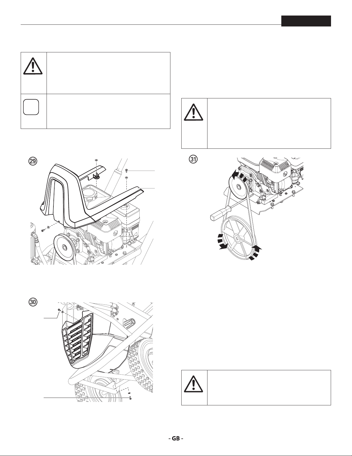
7.10 REPLACING THE BELT
PowrBeast
Before replacing the belt on your unit, make
sure you have performed the “Pressure Relief
Procedure” as illustrated in the Operation section
of this manual. DO NOT attempt this repair while
the unit is running.
The graphics below show a unit with a gas
engine. All instructions given in this section will
apply to both gas engine models and electric
motor models except where noted.
1. Remove the three screws and washers (1) that secure the
top shroud (2) to the cart frame. Remove the shroud.
1
2
4. With the screwdriver in place, use your other hand to
manually turn the belt and pulleys counterclockwise.
Allow the screwdriver to follow the motion of the pulley
and pry the belt outward at the same time. Continue to
turn the pulley approximately 1/2 turn and the belt will
slide o the upper pulley with the help of the screwdriver.
PINCH HAZARD. Make sure your ngers remain
clear of the contact area between the screwdriver
and the pulley. Do not allow your ngers to get
between the belt and pulley as it turns.
BURN HAZARD. Make sure the gas engine has
had time to suciently cool before touching it.
2. Remove the front screw (3) and the bottom screw (4) that
secures the lower shroud to the main unit. Remove the
entire shroud.
3
4
3. Carefully insert the driver end of a screwdriver in between
the belt and upper pulley as shown (g. 31).
REINSTALLATION
1. Loop the the new belt over the top pulley until the belt
engages the pulley groove.
2. Allow the belt to hang from the top pulley. With your
hand, hold the belt in place in approximately the 3:00
position on the lower pulley groove.
3. Use your other hand to manually turn the upper pulley
clockwise. Allow the hand holding the belt on the lower
pulley to follow the motion. The motion of the pulley and
the placement of your hand over the belt on the lower
pulley will allow the the belt to slide into place on the
lower pulley.
Make sure the belt is not pinched or twisted in
any way.
tention
4. Reverse steps 1-2 to reassemble the unit.
30
Page 31

troubleshooting
PowrBeast
8 TROUBLESHOOTING
8.1
AIRLESS GUN
PROBLEM
A. Spitting gun
B. Gun will not shut o
C. Gun does not spray
8.2 FLUID SECTION
PROBLEM
A. Pump delivers on upstroke only
or goes up slowly and down fast
(commonly called downstroke
dive)
B. Pump delivers on down stroke
only or goes up fast and down
slowly
C. Pump moves up and down fast,
delivering material
D. Pump moves up and down
slowly when spray gun is shut
o
E. Not enough uid pressure at
gun
F. Pump chatters on up or down
stroke
CAUSE
1. Air in system
2. Dirty gun
3. Needle assembly out of adjustment
4. Broken or chipped seat
1. Worn or broken needle & seat
2. Needle assembly out of adjustment
3. Dirty gun
1. No paint
2. Plugged lter or tip
3. Broken needle in gun
CAUSE
1. Lower foot valve ball is not seating due to
trash or wear
2. Material too viscous to siphon.
3. Air leaking in on siphon side or damaged
siphon hose. Siphon may be too small for
heavy material.
1. Upper ball is not seating due to trash or wear
2. Lower packing set is worn
1. Material container is empty or material is too
thick to ow through siphon hose
2. Bottom ball stuck to foot valve seat
3. Siphon hose is kinked or loose
1. Loose connections. Bleed valve is open
partially or bleed valve is worn. Lower
packing seat is worn.
2. Upper and/or lower ball not seating
1. Spray tip is worn
2. Outlet lter or gun lter is clogged
3. Low voltage and/or inadequate amperage
4. Hose size or length is too small or too long
1. Solvent has caused upper packing to swell
SOLUTION
1. Inspect connections for air leaks.
2. Disassemble and clean.
3. Inspect and adjust.
4. Inspect and replace.
1. Replace.
2. Adjust.
3. Clean.
1. Check uid supply.
2. Clean.
3. Replace.
SOLUTION
1. Remove foot valve assembly. Clean and inspect. Test
foot valve by lling with water; if ball fails to seal the
seat, replace ball.
2. Thin material — contact manufacturer for proper
thinning procedures.
3. Tighten all connections between pump and paint
container. If damaged, replace. Switch to larger diameter
siphon set.
1. Check upper seat and ball with water. If ball fails to seal,
replace seat.
2. Replace packing set if worn.
1. Rell with new material. If too thick, remove siphon
hose, immerse uid section in material, and start pump
to prime. Add thinner to material. Change to bigger
siphon set. Open bleed valve to remove air and restart
pump.
2. Remove foot valve. Clean ball and seat.
3. Straighten.
1. Check all connections between pump and gun. Tighten
as necessary. If material is owing from bleed hose, close
bleed valve or replace, if necessary. Should none of the
above be evident, replace lower packing.
2. Reseat balls by cleaning.
1. Replace.
2. Clean or replace lter.
3. Check electrical service. Correct as required.
4. Increase hose size to minimize pressure drop through
hose and/or reduce hose length.
1. Replace packing.
31
Page 32

troubleshooting
8.3 HYDRAULIC MOTORS
PowrBeast
PROBLEM
A. Hydraulic motor stalls at
bottom or top of stroke; low
or intermittent uid pump
pressure; unusual stroke speed;
high heat of the hydraulic oil
temperature (above 200ºF,
[93ºC]).
CAUSE
1. Low hydraulic oil level.
2. Pressure control setting too low.
3. Hydraulic belt or pulley failure.
4. Hydraulic piston failure.
5. Bound or broken uid section piston.
6. Hydraulic piston rod seal failure
7. Hydraulic piston head seal failure
8. Other
SOLUTION
1. Check oil level. Fill if necessary. If the oil level is full,
check the controller.
2. Make sure the pressure control knob is turned up
enough to cycle the motor. If the pressure control
setting is okay, then check the belt and pulleys.
3. Make sure the key is present in the output shaft of
the engine/electric motor and the input shaft of the
hydraulic pump. Make sure the belt is not broken and
has adequate tension. If belt and pulleys are okay,
please contact a Titan Authorized Service Center.
4. Visually check hydraulic piston rod for breaks. If a
broken hydraulic piston rod is apparent then remove/
replace hydraulic piston. Depending on where the
break occurred the piston coupler may also need to be
replaced. Please visit a Titan Authorized Service Center
if assistance is necessary. If hydraulic piston is okay then
check for bound/broken uid section piston
5. To check for a bound/broken uid section piston
de-couple the hydraulic piston from the paint piston
by removing the dowel pin. Power up the unit. If the
hydraulic motor cycles when the hydraulic piston is decoupled from the paint piston then the problem is most
likely in the uid section. Please visit a Titan Authorized
Service Center if assistance is necessary. If the hydraulic
motor still does not cycle then check the hydraulic
piston rod seal.
6. Remove the hydraulic piston rod seal plug which
contains the rod seal, O-ring, and rod wear ring. Check
for damage and replace rod seal, O-ring, or rod wear ring
if necessary. If rod seal, O-ring, and rod wear ring are
okay then check the hydraulic piston head seal.
7. Remove the hydraulic piston and inspect/replace the
piston head seal and piston head wear ring as needed.
During this process check the cylinder bore for damage
or uneven wear marks. If the cylinder bore is damaged
then replace pump block along with piston head seal
and piston head wear ring.
8. If problems persist please see a Titan Certied Service
Center.
32
Page 33

appendix
PowrBeast
8.4 SPRAY PATTERNS
PROBLEM
A. Tails
B. Hour glass
C. Distorted
D. Pattern expanding and
contracting (surge)
CAUSE
1. Inadequate uid delivery
1. Inadequate uid delivery
1. Plugged or worn nozzle tip
1. Suction leak
2. Pulsating uid delivery
SOLUTION
1. Fluid not atomizing correctly:
Increase uid pressure. Change to smaller tip orice size.
Reduce uid viscosity. Reduce hose length. Clean gun
and lter(s). Reduce number of guns using pump.
1. Same as above.
1. Clean or replace nozzle tip.
1. Inspect for suction hose leak.
2. Change to a smaller tip orice size. Install pulsation
dampener in system or drain existing one. Reduce
number of guns using pump. Remove restrictions in
system; clean tip screen if lter is used.
E. Round pattern
1. Worn tip
2. Fluid too heavy for tip
1. Replace tip.
2. Increase pressure. Thin material. Change nozzle tip.
33
Page 34

Übersetzung der originalbetriebsanleitung
Warnung!
Achtung: Verletzungsgefahr durch Injektion!
Airless-Geräte entwickeln extrem hohe Spritzdrücke.
Niemals Finger, Hände oder andere Körperteile mit dem Spritzstrahl
in Berührung bringen!
1
Nie die Spritzpistole auf sich, Personen und Tiere richten.
Nie die Spritzpistole ohne Spritzstrahl-Berührungsschutz benutzen.
Behandeln Sie eine Spritzverletzung nicht als harmlose Schnittver-
letzung. Bei einer Hautverletzung durch Beschichtungssto oder
Lösemittel sofort einen Arzt aufsuchen zur schnellen, fachkundigen
Behandlung. Informieren Sie den Arzt über den verwendeten
Beschichtungssto oder das Lösemittel.
PowrBeast
2
3
Vor jeder Inbetriebnahme sind gemäß Betriebsanleitung folgende
Punkte zu beachten:
1. Fehlerhafte Geräte dürfen nicht benutzt werden.
2. Titan-Spritzpistole sichern mit Sicherungshebel am Abzugsbügel.
3. Erdung sicherstellen.
4. Zulässigen Betriebsdruck von Hochdruckschlauch und Spritzpistole
überprüfen.
5. Alle Verbindungsteile auf Dichtheit prüfen.
Anweisungen zur regelmäßigen Reinigung und Wartung des
Gerätes sind streng einzuhalten.
Vor allen Arbeiten am Gerät und bei jeder Arbeitspause folgende
Regeln beachten:
1. Spritzpistole und Hochdruckschlauch druckentlasten.
2. Titan-Spritzpistole sichern mit Sicherungshebel am Abzugsbüge.
3. Gerät ausschalten.
34
Achte auf Sicherheit!
Page 35

inhalt
PowrBeast
1 SICHERHEITSVORSCHRIFTEN FÜR DAS
AIRLESSSPRITZEN _____________________ 36
1.1 Erklärung der verwendeten Symbole _____________36
1.2 Sicherheitsrisiken _____________________________ 36
1.3 Aufstellung in unebenem Gelände _______________ 38
1.4 Elektrische Sicherheit __________________________ 38
1.5 Benzinmotoren-Betriebssicherheit _______________38
1.6 Betanken (Benzinmotor) _______________________39
2 ANWENDUNGSÜBERSICHT ______________40
2.1 Einsatzgebiete _______________________________40
2.2 Beschichtungsstoe __________________________40
3 GERÄTEBESCHREIBUNG _________________41
3.1 Airless-Verfahren _____________________________41
3.2 Funktion des Gerätes __________________________ 41
3.3 Erklärungsbild PowrBeast-Geräte mit Benzinmotor _42
3.4 Erklärungsbild PowrBeast-Geräte mit Elektromotor _43
3.5 Technische Daten PowrBeast-Geräte _____________44
3.6 Transport ___________________________________45
4 BEDIENUNG ____________________________45
4.1 Einrichtung __________________________________ 45
4.2 Start des Benzinmotors (Benzinmodelle) __________47
4.3 Vorbereitung eines neuen Spritzgeräts ___________47
4.4 Vorbereitung der Farbe ________________________48
4.5 Farbgebung _________________________________49
4.6 Vorgehensweise bei Druckentlastung ____________49
5 SPRITZTECHNIK ________________________50
5.1 Eine verstopfte Düse reinigen ___________________ 50
5.2 Arbeitsunterbrechung _________________________ 51
5.3 Handhabung des Hochdruck-schlauches __________ 51
7 UNTERHALT ____________________________54
7.1 Tägliche Wartung _____________________________ 54
7.2 Die oberen Dichtungen einfetten ________________54
7.3 Unterhalt des Filteraufbaus _____________________ 54
7.4 Unterhalt des hydraulischen Systems _____________ 55
7.5 Unterhalt des Flüssigkeitsbereichs _______________56
7.6 Hochdruckschlauch ___________________________56
7.7 Einfacher Unterhalt des Motors (Benzinmotor) _____57
7.8 Wartung des Hydraulikmotors __________________58
7.9 Unterhalt des Flüssigkeitsbereiches ______________60
7.10 Auswechseln des Riemens _____________________62
8 FEHLERBEHEBUNG _____________________63
8.1 Airless-Spritzpistole ___________________________63
8.2 Flüssigkeitsbereich ___________________________63
8.3 Hydraulikmotor ______________________________64
8.4 Spritzmuster _________________________________ 65
ZUBEHÖR UND ERSATZTEILE _________________98
Ersatzteilliste Hauptbaugruppe I ___________________ 98/99
Ersatzteilliste Hauptbaugruppe II ________________ 100/101
Ersatzteilliste Wagen __________________________ 102/103
Ersatzteilliste Hydrauliksystem __________________ 104/105
Ersatzteilliste Flüssigkeitsbereich •
PowrBeast 4700 / PowrBeast 4700T ______________ 106/107
Ersatzteilliste Flüssigkeitsbereich •
PowrBeast 7700 / 9700 _________________________ 108/109
Ersatzteilliste Hydraulikmotors __________________ 110/111
Ersatzteilliste Hochdrucklter ___________________ 112/113
Ersatzteilliste Ablassventilbaugruppe _________________114
Ersatzteilliste Ablassventilbaugruppe,
schwere Anstrichen _______________________________115
Ersatzteilliste für die Magnetbaugruppe ___________ 116/117
6 REINIGUNG ____________________________52
6.1 Besondere Reinigungshinweise bei Verwendung
entflammbarer Lösungsmittel __________________52
6.2 Reinigung des Spritzgeräts _____________________52
6.3 Gerätereinigung von außen ____________________52
6.4 Den Steinfänger reinigenAnsauglter ____________53
6.5 Reinigung der Airless-Spritzpistole _______________ 53
SCHALTPLAN 120V ________________________ 118
SCHALTPLAN 230V ________________________ 119
SCHALTPLAN BENZINMOTOR ______________120
HYDRAULIKSCHEMA ________________________121
ZUBEHÖR FÜR POWRBEASTGERÄTE _____122/123
GARANTIE _________________________________126
35
Page 36

sicherheitsvorschriften
i
Eine unter hohem Druck stehende Flüssigkeit,
Bindegewebe eindringen und so zu schweren
Behandeln Sie eine Spritzverletzung nicht
als harmlose Schnittver-letzung. Bei einer
Hautverletzung durch Beschichtungssto
oder Lösemittel sofort einen Arzt aufsuchen
zur schnellen, fachkundigen Behandlung.
PowrBeast
1 SICHERHEITSVORSCHRIFTEN FÜR
DAS AIRLESSSPRITZEN
1.1
Diese Bedienanleitung enthält Informationen, die der Benutzer
vor Verwendung des Geräts gründlich durcharbeiten muss. In
Bereichen, die mit den folgenden Symbolen gekennzeichnet
sind, besonders vorsichtig arbeiten und alle Sicherheitshinweise
beachten.
ERKLÄRUNG DER VERWENDETEN SYMBOLE
Dieses Symbol verweist auf eine
potenzielle Gefahr, die zum Tode
oder zu schweren Verletzungen
führen kann. Hier nden Sie wichtige
Sicherheitsinformationen.
Dieses Symbol weist auf eine potenzielle
Gefahr für Sie bzw. das Gerät hin. Unter
Achtung
diesem Symbol nden Sie wichtige
Informationen, wie Sie Schäden an dem
Gerät und Verletzungsgefahr vermeiden.
Injektionsgefahr
Brandgefahr durch Lösemittel und
Farbdämpfe
Explosionsgefahr durch Lösemittel,
Farbdämpfe und ungeeignete Materialien
Verletzungsgefahr durch das Einatmen von
schädlichen Dämpfen
Verletzungsgefahr durch Stromschlag
Hinweise enthalten wichtige Informationen,
die beachtet werden sollten.
1.2 SICHERHEITSRISIKEN
GEFAHR: VERLETZUNG DURCH
FLÜSSIGKEITEN UNTER DRUCK
wie sie von diesem Gerät erzeugt wird, kann die
Haut durchdringen und in das darunter liegende
Verletzungen und selbst zur Amputation führen.
Informieren Sie den Arzt über den verwendeten
Beschichtungssto oder das Lösemittel.
VORSICHTSMASSNAHMEN:
• NIEMALS die Spritzpistole auf Körperteile halten.
• NIEMALS mit Körperteilen den Flüssigkeitsstrahl berühren.
NIEMALS mit dem Körper eine Leckstelle im Druckschlauch
berühren.
• NIEMALS die Hand vor die Düse der Spritzpistole
halten. Handschuhe stellen keinen sicheren Schutz vor
Verletzungen durch injizierte Flüssigkeiten dar.
• STETS den Auslöser der Spritzpistole verriegeln, die Pumpe
ausschalten und den Druck vollständig entspannen,
bevor Wartungs- und Reinigungsarbeiten, Durchsichten,
Düsenwechsel oder ähnliche Arbeiten durchgeführt
werden oder das Gerät unbeaufsichtigt gelassen wird.
Auch nach dem Ausschalten des Motors steht das Gerät
noch unter Druck. Das Ventil PRIME/SPRAY (Vorfüll-/
Sprühventil) bzw. das Druckentlastungsventil müssen
in ihren Sollpositionen stehen, um den Systemdruck zu
entspannen.
• STETS den Düsenschutz aufsetzen, wenn Spritzarbeiten
durchgeführt werden. Der Düsenschutz stellt einen
gewissen Schutz dar, ist aber vor allem als Warnvorrichtung
gedacht.
• STETS die Spritzdüse entfernen, bevor das System gereinigt
oder gespült wird.
• NIEMALS eine Spritzpistole ohne funktionsfähige
Auslöserverriegelung und ohne Auslöserbügel verwenden.
• Das gesamte Zubehör muss mindestens für den maximalen
Betriebsdruckbereich des Spritzgeräts zugelassen sein.
Dazu gehören Spritzdüsen, Spritzpistolen, Verlängerungen
und Schlauch.
36
Page 37

sicherheitsvorschriften
Durch Verschleiß, Knicken und nicht
zweckentsprechende Verwendung können
sich Leckstellen im Farbschlauch bilden. Durch
eine Leckstelle kann Flüssigkeit in die Haut
injiziert werden. Vor Verwendung den Schlauch
Brennbare Dämpfe, wie z. B. Dämpfe von
PowrBeast
• Nur elektronische Modelle -Verwenden Sie keine Materialien
GEFAHR: HOCHDRUCKSCHLAUCH
mit einem Flammpunkt unter 38°C (100°F). Der Flammpunkt
ist die Temperatur, bei der eine Flüssigkeit ausreichend
Dämpfe entwickeln kann, dass sich diese entzünden.
• Nur Modelle mit Benzin - Befüllen Sie den Treibstotank
nicht, wenn der Motor läuft oder heiß ist; schalten Sie den
Motor ab und lassen diesen abkühlen. Der Treibsto ist
gründlich prüfen.
VORSICHTSMASSNAHMEN:
• Scharfes Biegen oder Knicken des Hochdruckschlauches
vermeiden, kleinster Biegeradius etwa 20 cm.
• Hochdruckschlauch nicht überfahren, sowie vor scharfen
Gegenständen und Kanten schützen.
• Beschädigten Hochdruckschlauch sofort ersetzen.
• Niemals defekten Hochdruckschlauch selbst reparieren!
• Elektrostatische Auadung von Spritzpistole und
Hochdruckschlauch wird über den Hochdruckschlauch
abgeleitet. Deshalb muss der elektrische Widerstand
zwischen den Anschlüssen des Hochdruckschlauchs gleich
oder kleiner ein Megaohm betragen.
• Aus Gründen der Funktion, Sicherheit und Lebensdauer,
nur Titan-Original-Ersatzhochdruckschläuche verwenden.
• Vor jedem Einsatz alle Schläuche auf Einschnitte,
Leckstellen, Scheuerstellen oder gewölbte Oberächen
kontrollieren. Die Kupplungen auf Unversehrtheit und
festen Sitz kontrollieren. Schläuche unverzüglich ersetzen,
wenn einer der oben genannten Fehler festgestellt wird.
Einen Farbschlauch niemals reparieren. Einen defekten
Schlauch durch einen geerdeten Hochdruckschlauch
ersetzen.
• Achten Sie darauf, Spritzschläuche so zu verlegen, dass die
Rutsch-, Stolper-, und Umfallgefahr minimiert wird.
brennbar und kann sich entzünden bzw. explodieren, wenn
dieser mit einer heißen Oberäche in Berührung kommt.
• Beseitigen Sie alle Zündquellen, wie z. B. Zündammen,
Zigaretten, tragbare elektrische Lampen und
Plastikabdeckplanen (potenzieller elektrostatischer
Lichtbogen).
• Halten Sie die Arbeitsbereiche frei von Verunreinigungen,
einschließlich Lösungsmittel, Lappen und Benzin.
• Schließen Sie die Elektrozuleitungen nicht bzw. bzw.
trennen diese nicht ab bzw. schalten Sie die Netzschalter
bzw. Lichtschalter nicht ein bzw. aus, wenn sich brennbare
Dämpfe entwickelt haben.
• Schutzleiter und leitfähige Gegenstände im Arbeitsbereich.
Achten Sie darauf, dass die Erdleitung (in der Lieferung
nicht enthalten) von der Erdungsklemme mit einem
wirksamen Erdungsanschluss verbunden ist.
• Verwenden Sie ausschließlich geerdete Schläuche.
• Halten Sie die Spritzpistole fest an die Seite eines geerdeten
Eimers, wenn Sie in den Eimer spritzen.
• Kommt es durch statische Auadung zu Funkenbildung
bzw. wenn Sie einen Stromschlag verspüren, brechen Sie
den Vorgang umgehend ab.
• Sie müssen die Zusammensetzung der Farben und
Lösungsmittel, die Sie spritzen möchten, kennen. Lesen
Sie alle Materialsicherheitsdatenblätter (MSDS) und
Behälterbeschriftungen von Farben und Lösungsmitteln
durch. Befolgen Sie die Sicherheitsanweisungen des
Farben- und Lösungsmittelherstellers.
• Verwenden Sie keine Farben bzw. Lösungsmittel, die
GEFAHR: EXPLOSIONS UND
BRANDGEFAHR
Lösungsmitteln und Farben können sich in den
Arbeitsbereichen entzünden oder explodieren.
Halogenkohlenwasserstoe enthalten, wie z. B. Chlor,
Bleiche, Antischimmelmittel, Methylenchlorid und
Trichlorethan. Sie sind nicht kompatibel mit Aluminium.
Setzen Sie sich mit dem Lieferanten der Beschichtung
hinsichtlich der Kompatibilität des Materials mit Aluminium
in Verbindung.
• Halten Sie im Arbeitsbereich einen Feuerlöscher bereit.
VORSICHTSMASSNAHMEN:
• Verwenden Sie das Gerät ausschließlich in gut belüfteten
Bereichen. Achten Sie auf ausreichende Frischluftzufuhr im
gesamten Bereich, damit sich keine brennbaren Dämpfe in
der Luft im Spritzbereich ansammeln können. Bewahren
Sie die Pumpenbaugruppe in einem gut belüfteten Bereich
auf. Besprühen Sie nicht die Pumpenbaugruppe.
37
Page 38

sicherheitsvorschriften
Farben, Lösungsmittel und andere Materialien
können beim Einatmen oder beim Kontakt mit
dem Körper gesundheitsschädlich sein. Die
Dämpfe können schwere Übelkeit, Ohnmacht
Kann schwere Personen- oder Sachschäden
GEFAHR: GEFÄHRLICHE DÄMPFE
und Vergiftungen verursachen.
VORSICHTSMASSNAHMEN :
• Bei Spritzarbeiten Atemschutz tragen. Alle mit der
Gesichtsmaske mitgelieferten Anleitungen durcharbeiten,
damit die Gesichtsmaske auch den gewünschten Schutz
bietet.
• Dem Benutzer ist eine Atemschutzmaske zur Verfügung
zu stellen (Berufs-Genossenschaftliche Regeln „Regeln für
den Einsatz von Atemschutzgeräten“ (BGR 190).
• Arbeitsschutzbrille tragen.
• Zum Schutz der Haut sind Schutzkleidung, Handschuhe
und eventuell Hautschutzcreme erforderlich (BGR 197
“Benutzung von Hautschutz”). Vorschriften der Hersteller
beachten zu den Beschichtungsstoen, Lösemittel und
Reinigungsmittel bei Aufbereitung, Verarbeitung und
Gerätereinigung.
GEFAHR: ALLGEMEINES
verursachen.
PowrBeast
1.3 AUFSTELLUNG IN UNEBENEM GELÄNDE
Die Vorderseite muss nach unten zeigen, um ein Wegrutschen
zu vermeiden.
Auf schrägen Untergründen ist das Gerät nicht zu betreiben, da
es durch Vibrationen zum Wandern neigt.
1.4 ELEKTRISCHE SICHERHEIT
Elektrogeräte müssen geerdet werden. Bei einem elektrischen
Kurzschluss reduziert die Erdung die Gefahr eines elektrischen
Schlages, da der Fehlerstrom über den Schutzleiter abgeführt
wird. Dieses Gerät ist mit einem Netzkabel versehen, das einen
Schutzkontaktstecker besitzt. Anschluss an das Stromnetz
nur über einen besonderen Speisepunkt z. B. über eine
Fehlerstromschutzeinrichtung mit INF≤ 30 mA.
VORSICHTSMASSNAHMEN :
• Alle lokalen sowie im Land bzw. Bundesland geltenden
Vorschriften zum Brandschutz, zur Bedienung und Lüftung
einhalten.
• Bei Betätigung des Auslösers zieht die Spritzpistole zur
Seite. Diese Kraftwirkung der Spritzpistole ist besonders
stark, wenn die Düse entfernt und bei der Pumpe
hoher Druck eingestellt wurde. Bei der Reinigung mit
abgeschraubter Düse daher den Druckreglerknopf auf den
niedrigsten Druck einstellen.
• Nur vom Hersteller zugelassene Teile verwenden. Bei
Verwendung von Teilen, die nicht die technischen
Mindestanforderungen erfüllen, trägt der Benutzer alle
Risiken und die gesamte Haftung. Dies gilt auch für die
Sicherheitsvorrichtungen der Pumpe.
• IMMER die Hinweise des Herstellers zum sicheren Umgang
mit Farben und Lösungsmitteln einhalten.
• Verschüttete Materialien und Lösemitteln sofort
aufwischen, um Rutschgefahr zu vermeiden.
• Gehörschutz tragen. Dieses Gerät kann einen Schalldruck
über 85 dB(A) erzeugen.
• Das Gerät niemals unbeaufsichtigt lassen. Kinder oder
andere Personen, die mit dem Betrieb des druckluftlosen
Spritzgeräts nicht vertraut sind, von dem Gerät fern halten.
• An windigen Tagen nicht im Freien spritzen.
• Das Gerät inklusive aller Flüssigkeiten (z.B. Hydrauliköl)
müssen umweltgerecht entsorgt werden.
38
GEFAHR — Arbeiten oder Reparaturen an
der elektrischen Ausrüstung nur von einer
Elektrofachkraft durchführen lassen. Für
unsachgemäße Installation wird keine Haftung
übernommen. Gerät ausschalten. Vor allen
Reparaturen – Netzstecker aus der Steckdose ziehen.
Gerätereinigung: Kurzschlussgefahr durch
eindringendes Wasser in die elektrische
Ausrüstung. Gerät niemals mit Hochdruck- oder
Dampfhochdruckreiniger abspritzen.
1.5 BENZINMOTORENBETRIEBSSICHERHEIT
1. Benzinmotoren sind so gebaut, dass sie sicher und
verlässlich funktionieren, wenn sie gemäss der
Instruktionen bedient werden. Vor der Bedienung des
Motos muss das Besitzerhandbuch des Herstellers
gelesen und verstanden werden. Bei Unterlassung kann
Personenverletzung oder Materialschaden entstehen.
2. Um Feuergefahr zu vermeiden und genügend Ventilation
zu erlauben, muss der Motor mindestens 1 Meter von
Gebäuden und anderen Maschinen entfernt sein wenn er
in Betrieb ist. Keine brennbaren Gegenstände in der Nähe
des Motors aufbewahren.
3. Personen, die das Gerät nicht bedienen, dürfen den
Betriebsbereich nicht betreten, da die Möglichkeit
besteht Verbrennungen von heissen Motorenteilen oder
Page 39
sicherheitsvorschriften
Ac
i
i
PowrBeast
Verletzungen durch Geräte, die zur Bedienung des Motors
benutzt werden, zu erleiden.
4. Seien Sie vertraut damit, wie Sie den Motor schnell
abstellen können und wissen Sie Bescheid über alle
Bedienungselemente und deren Handhabung. Erlauben
Sie niemandem, den Motor ohne sachgerechte Anleitung
zu bedienen.
5. Benzin ist äusserst ammbar und unter bestimmten
Bedingungen explosiv.
6. Tanken Sie Benzin nur in einem gut durchlüfteten Bereich
nach, nachdem der Motor abgestellt wurde. Rauchen
Sie nicht und erlauben Sie keine Flammen oder Funken
im Bereich in welchem aufgetankt wird oder Benzin
aufbewahrt wird.
7. Ueberfüllen Sie den Benzintank nicht. Nach dem Auftanken,
vergewissern Sie sich, dass die Tankverschlusskappe
richtig und sicher aufgeschraubt ist.
8. Seien Sie darauf bedacht, beim Auftanken kein Benzin zu
verschütten. Benzindämpfe oder verschüttetes Benzin
könnte sich entammen. Falls Benzin verschüttet wurde,
vergewissern Sie sich, dass der Bereich trocken ist, bevor
Sie den Motor starten.
9. Lassen Sie den Motor nie in einem geschlossenen oder engen
Bereich laufen. Abgase enthalten giftige Kohlenmonoxidgase;
diesen ausgesetzt läuft man Gefahr das Bewusstsein zu
verlieren und es kann soagar zu Tod führen.
10. Der Auspu wird während des Laufen des Motors sehr
heiss und bleibt nach abstellen des Motors noch für
eine Weile heiss. Seien Sie darauf Bedacht, den Auspu
nicht zu berühren, solange er noch heiss ist. Um schwere
Verbrennungen oder Feuergefahr zu vermeiden, lassen
Sie den Motor abkühlen, bevor Sie ihn transportieren oder
in einem Innenraum aufbewahren.
11. Verschien oder transportieren Sie die Sprühanlage
niemals mit Benzin im Tank.
Benutzen Sie diese Anlage NICHT um Wasser
oder Säuren zu spritzen.
Die Verwendung eines Treibstoes mit einer geringeren
Oktanzahl kann zu ständigem “Motorklopfen” oder
starkem “Klopfen” (ein metallisches klopfendes Geräusch)
führen, das zu einem Motorschaden führen kann, wenn
dieser zu stark ist.
Wechseln Sie die Treibstomarke, wenn das
“Klopfen” oder “Motorklopfen” bei einer stetigen
Motorgeschwindigkeit unter normaler Belastung
auftritt. Bleibt das Klopfen bzw. Motorklopfen,
setzen Sie sich mit einem autorisierten Händler
des Motorherstellers in Verbindung. Bei
Nichteinhaltung gilt dies als Fehlgebrauch und
Schäden durch Fehlgebrauch sind nicht durch
die Herstellergarantie gedeckt.
Gelegentlich entsteht ein leichtes Klopfen, wenn
das Gerät stark belastet wird. Das ist kein Grund
zur Beunruhigung. Dies bedeutet nur, dass der
Motor ezient funktioniert.
• Bleifreier Treibsto verursacht weniger Ablagerungen
im Motor und in den Zündkerzen und verlängert die
Lebensdauer der Komponenten des Abgassystems.
• Verwenden Sie niemals abgestandenes oder verschmutztes
Benzin und/oder ein Öl-/Benzingemisch. Vermeiden Sie,
dass Schmutz, Staub oder Wasser in den Treibstotank
gelangen.
KRAFTSTOFF AUS BENZINALKOHOLGEMISCH
Wenn Sie sich für einen Kraftsto aus einem Benzin-Alkohol-Gemisch
(Gasohol) entscheiden, müssen Sie darauf achten, dass dessen
Oktanzahl mindest so hoch ist, wie diese vom Motorenhersteller
empfohlen wird. Es gibt zwei Arten von Benzin-Alkohol-Gemisch:
die eine enthält Ethanol und die andere Methanol. Verwenden
Sie kein Gasohol, das mehr als 10 % Ethanol enthält. Verwenden
Sie kein Benzin-Methanol-Gemisch (Methyl oder Holzalkohol),
das keine Zusatzlösungsmittel und Korrosionshemmstoe für
Methanol enthält. Verwenden Sie niemals Benzin, das mehr als 5 %
Methanol enthält, auch dann nicht, wenn es Zusatzlösungsmittel
und Korrosionshemmstoe enthält.
Eine Beschädigung des Treibstosystems bzw.
Beim Auf- oder Abladen, nicht an der Deichsel
halten.
htung
Gerät ist sehr schwer. Muss von drei Personen
getragen werden.
1.6 BETANKEN BENZINMOTOR
Benzin ist äußerst entammbar und unter
bestimmten Bedingungen sogar explosiv.
TECHNISCHE ANGABEN ZUM TREIBSTOFF
• Verwenden Sie Benzin mit einer Mindest-Oktanzahl von
86 oder mit einer Mindest-Research-Oktanzahl von 91.
39
Probleme mit der Motorenleistung, die aus der
Verwendung von Treibsto resultieren, der
Alkohol enthält, werden von der Gewährleistung
nicht gedeckt. Der Motorenhersteller kann nicht
die Verwendung von Treibstoen befürworten,
die Methanol enthalten, das es noch nicht als
erwiesen gilt, dass sich diese hierfür eignen.
Versuchen Sie herauszunden, ob das Benzin
Alkohol enthält, bevor Sie Benzin von einer Ihnen
unbekannten Tankstelle beschaen. Falls dieses
Alkohol enthält, überprüfen Sie die Art und den
Anteil des verwenden Alkohols. Stellen Sie bei
der Verwendung von alkoholhaltigem Benzin
bzw. von dem Sie annehmen, dass es Alkohol
enthält, unerwünschtes Betriebsverhalten fest,
stellen Sie auf ein Benzin um, von dem Sie wissen,
dass es kein Alkohol enthält.
Page 40

anwendungsÜbersicht
i
i
2 ANWENDUNGSÜBERSICHT
PowrBeast
2.1
Hauptanwendungsgebiete sind dicke Schichten von
höherviskosem Beschichtungssto bei großen Flächen und
hohem Materialeinsatz.
Grundierung und Schlussbeschichtung von Großächen,
Versiegelung, Imprägnierung, Bausanierung, Fassadenschutz
und Fassadenrenovierung, Rostschutz und Bautenschutz,
Dachbeschichtung, Dachabdichtung, Betonsanierung, sowie
schwerer Korrosionsschutz.
SPRITZOBJEKTBEISPIELE
Großbaustellen, Tiefbau, Kühltürme, Brücken, Kläran lagen und
Flachdächer.
EINSATZGEBIETE
2.2 BESCHICHTUNGSSTOFFE
VERARBEITBARE BESCHICHTUNGSSTOFFE
Wasserverdünnbare und lösemittelhaltige Lacke und
Lackfarben, Zweikomponenten Beschichtungsstoe,
Dispersionen, Latexfarben.
Die Verarbeitung anderer Beschichtungsstoe sollte nur nach
Rückfrage bei der Firma Titan erfolgen, da die Haltbarkeit und
auch die Sicherheit des Gerätes dadurch beeinträchtigt werden
können.
Achten Sie auf Airless-Qualität bei den zu
verarbeitenden Beschichtungsstoen.
VISKOSITÄT
Das Gerät ist in der Lage Beschichtungsstoe mit einer
Viskosität bis zu 50.000 / 65.000 mPas zu verarbeiten. Lässt die
Spritzleistung bei hochviskosen Beschichtungsstoen zu stark
nach, so ist nach Herstellerangabe zu verdünnen.
Beschichtungssto vor Arbeitsbeginn gut umrühren.
Achtung: Beim Aufrühren mit motorgetriebenen
Rührwerken darauf achten, dass keine
Luftblasen eingerührt werden. Luftblasen
stören beim Spritzen, können sogar zur
Betriebsunterbrechung führen.
BESCHICHTUNGSSTOFFE MIT SCHARFKANTIGEN
ZUSATZSTOFFEN
Diese Partikel üben auf Ventile und Düse, aber auch auf die
Spritzpistole eine stark verschleißende Wirkung aus. Die
Lebensdauer dieser Verschleißteile wird dadurch erheblich
beeinträchtigt.
ZWEIKOMPONENTENBESCHICHTUNGSSTOFF
Die entsprechende Verarbeitungszeit ist genau einzuhalten.
Innerhalb dieser Zeit das Gerät sorgfältig mit dem
entsprechenden Reinigungsmittel durchspülen und reinigen.
FILTERUNG
Für einen störungsfreien Betrieb ist eine ausreichende
Filterung erforderlich. Das System ist mit einem Sauglter,
einem Einschublter in der/den Spritpistole(n) und einem
Hochdrucklter am System ausgestattet. Eine regelmäßige
Kontrolle dieser Filter auf Beschädigung oder Verschmutzung
ist dringend zu empfehlen.
40
Page 41

gerätebeschreibung
i
2
PowrBeast
3 GERÄTEBESCHREIBUNG
3.1
Hauptanwendungsgebiete sind dicke Schichten von
höherviskosem Beschichtungssto bei großen Flächen und
hohem Materialeinsatz.
Eine Kolbenpumpe saugt den Beschichtungssto an und
fördert ihn unter Druck zur Düse. Bei einem Druck bis max.
228 bar (22,8 MPa) durch die Düse gepresst, zerstäubt der
Beschichtungssto. Dieser hohe Druck bewirkt eine mikrofeine
Zerstäubung des Beschichtungsstoes.
Da in diesem System keine Luft verwendet wird, bezeichnet
man dieses Verfahren als AIRLESS-Verfahren (luftlos).
Diese Art zu spritzen bringt die Vorteile von feinster Zerstäubung,
nebelarmer Betriebsweise und glatter, blasenfreier Oberäche.
Neben diesen Vorteilen sind die Arbeits geschwindigkeit und
die große Handlichkeit zu nennen.
AIRLESS VERFAHREN
3.2 FUNKTION DES GERÄTES
Zum besseren Verständnis der Funktion kurz der technischen
Aufbau.
Dieses Handbuch bietet Ihnen Informationen
sowohl zu elektrischen Motoren als auch
Benzinmotoren des Typs PowrBeast.
TITAN PowrBeast sind mit Benzinmotor oder Elektromotor
angetriebene Hochdruckspritzgeräte.
Der Benzinmotor oder Elektromotor (Abb. 1, Pos. 1) treibt
über den Keilriemen unter der Riemenabdeckung (2) die
Hydraulikpumpe (3) an. Hydrauliköl ießt zum Hydraulikmotor
(4) und bewegt dann den Kolben in der Materialförderpumpe
(5) auf und ab.
Durch die Aufwärtsbewegung des Kolbens önet das
Einlassventil selbstständig. Bei der Abwärtsbewegung des
Kolbens önet das Auslassventil.
Der Beschichtungssto strömt unter hohem Druck durch den
Hochdruckschlauch zur Spritzpistole. Bei Austritt aus der Düse
zerstäubt der Beschichtungssto.
Das Druckregelventil (6) regelt die Fördermenge und den
Betriebsdruck des Beschichtungsstos.
1
4
6
5
3
41
Page 42

gerätebeschreibung
3.3 ERKLÄRUNGSBILD POWRBEASTGERÄTE MIT BENZINMOTOR
PowrBeast
1. Deichsel ausziehbar
2. Einfüllönung für Trennöl
(Trennöl verhindert erhöhten
Verschleiß der Packungen)
3. Hochdrucklter
4. Hochdruckschlauchauslass
5. Hydraulikmotor
2
3
4
6. Entlastungsventilhandgri
Nach links drehen Zirkulation k
Nach rechts drehen Spritzen p
7. Rücklaufschlauch
8. Ansaugschlauch
9. Keilriemen unter der Riemenabdeckung
10. Benzinmotor
1
11. Ölmessstab
12. Druckregulierknopf
13. Düsenschutzvorrichtung mit Airless
Düse
14. Spritzpistole
15. Hochdruckschlauch
10
5
6
4700
11
12
13
7
8
14
15
9
42
Page 43

gerätebeschreibung
PowrBeast
3.4 ERKLÄRUNGSBILD POWRBEASTGERÄTE MIT ELEKTROMOTOR
1. Deichsel ausziehbar
2. Einfüllönung für Trennöl
(Trennöl verhindert erhöhten
Verschleiß der Packungen)
3. Hochdrucklter
4. Hochdruckschlauchauslass
5. Hydraulikmotor
2
3
4
6. Entlastungsventilhandgri
Nach links drehen Zirkulation k
Nach rechts drehen Spritzen p
7. Rücklaufschlauch
8. Ansaugschlauch
9. Keilriemen unter der Riemenabdeckung
10. Elektromotor
11. EIN/AUS-Schalter
1
12. Kontrollleuchte zeigt
Betriebsbereitschaft an
13. Ölmessstab
14. Druckregulierknopf
15. Düsenschutzvorrichtung mit Airless
Düse
16. Spritzpistole
17. Hochdruckschlauch
10
11
12
13
5
14
6
15
7
16
17
8
9
43
Page 44

gerätebeschreibung
3.5 TECHNISCHE DATEN
PowrBeast
PowrBeast 4700T
(120V)
Benzinmotor, Leistung
Honda
Tankinhalt
Spannung
Aufnahmeleistung
Geräteanschlussleitung
Absicherung
max. Betriebsdruck
max. Schalldruckpegel:
max. Düsengröße mit einer Spritzpistole
1-Spritzpistole 0,035” – 0.89 mm 0,035” – 0.89 mm 0,041” – 1,04 mm 0,043” – 1,09 mm 0,047” – 1,19 mm 0,055” – 1,40 mm
2-Spritzpistole 0,023” – 0,58 mm 0,023” – 0,58 mm 0,029” – 0,73 mm 0,031” – 0,79 mm 0,033” – 0,84 mm 0,039” – 0,99 mm
3-Spritzpistole 0,019” – 0,48 mm 0,019” – 0,48 mm 0,021” – 0,53 mm 0,023” – 0,58 mm 0,027” – 0,68 mm 0,031” – 0,79 mm
4-Spritzpistole -------- -------- 0,019” – 0,48 mm 0,021” – 0,53 mm 0,023” – 0,58 mm 0,027” – 0,68 mm
max. Volumenstrom
Gewicht
Ansaugsystem
max. Viskosität
Abmessungen L x H x B
max. Temperatur des Beschichtungsstos
Filtereinsatz (Standardausführung)
Hydrauliköl-Füllmenge
max. Reifendruck
Spezial-Hochdruckschlauch
-------- --------
-------- -------- 3,1 l -------- 3,1 l 6,06 l
~ 120V, 50/60 Hz ~ 120V, 50/60 Hz -------- ~ 230V, 50/60 Hz -------- --------
1,3 kW 1,3 kW -------- 3,1 kW -------- --------
3 x 2.5 mm – 6 m 3 x 2.5 mm – 6 m -------- 3 x 2.5 mm – 6 m -------- --------
15 A 15 A -------- 15 A -------- --------
22,8 MPa (228 bar) 22,8 MPa (228 bar) 22,8 MPa (228 bar) 24,8 MPa (248 bar) 22,8 MPa (228 bar) 22,8 MPa (228 bar)
80 dB (A)* 80 dB (A)* 92 dB (A)* 80 dB (A)* 92 dB (A)* 98 dB (A)*
4,75 l/min 4,75 l/min 6,00 l/min 6,00 l/min 7,60 l/min 11,4 l/min
85 kg 82 kg 78 kg 85 kg 81 kg 90 kg
Tauchfähig Standard Standard Tauchfähig Tauchfähig Tauchfähig
--------
DN 10 mm, 15 m,
Anschlussgewinde
NPSM 1/4
PowrBeast 4700
(120V)
50.000 mPa·s 65.000 mPa·s
Filterfeinheit 50,
18 in
PowrBeast 4700
(gas)
163cc, 4.9 Hp, 3.6
kW
1090 x 660 x 866 mm
Filterfeinheit 50,
18 in
5,9 l (1,56 gal) CoolFlo
0,2 MPa (2 bar, 30 PSI)
DN 6 mm, 15 m, Anschlussgewinde NPSM 1/4
PowrBeast 7700
(230V)
--------
43° C
Filterfeinheit 0,
18 in
PowrBeast 7700
(gas)
196cc, 5.6 Hp, 4.1 kW270cc, 8.4 Hp, 6.2
Filterfeinheit 50,
18 in
PowrBeast 9700
(gas)
kW
Filterfeinheit 5,
18 in
* Messort: Abstand 1 m seitlich vom Gerät und 1,60 m über schallhartem Boden, 12 MPa (120 bar) Betriebsdruck.
44
Page 45

gerätebeschreibung / bedienung
i
PowrBeast
4 BEDIENUNG
BETRIEBSTEMPERATUR
Dieses Gerät funktioniert einwandfrei in seiner für ihn
vorgesehen Raumtemperatur zwischen +10°C und +40°C.
RELATIVE FEUCHTIGKEIT
Das Gerät funktioniert in einem Umfeld mit einer relativen
Feuchtigkeit von 50%, bei +40°C einwandfrei. Eine höhere
relative Feuchtigkeit stellt bei niedrigeren Temperaturen kein
Problem dar.
Der Käufer des Geräts muss Maßnahmen ergreifen, um die
schädigenden Auswirkungen der gelegentlichen Kondensation
zu vermeiden.
HÖHE
Dieses Gerät funktioniert in einer Höhe von bis zu 2100m über
n.n. einwandfrei.
TRANSPORT UND AUFBEWAHRUNG
Dieses Gerät hält Transport- bzw. Aufbewahrungstemperaturen
von -25°C bis + 55°C, kurzzeitig auch bis zu +70°C, stand bzw. ist
dagegen geschützt.
Es wurde so verpackt, dass es Beschädigungen durch die
Auswirkungen von normaler Feuchtigkeit, Erschütterungen
und Stößen standhält.
4.1 EINRICHTUNG
1. Achten Sie darauf, dass der Entlüftungsschlauch (Abb.
2. Schließen Sie einen mindestens 15 m langen Airless
Diese Komponente produziert einen
Flüssigkeitsstrom bei extrem hohem Druck. Lesen
und verstehen Sie die Hinweise im Abschnitt über
die Sicherheitsvorkehrungen am Anfang dieses
Handbuches, bevor Sie dieses Gerät benutzen.
6, Pos. 1) an das Entlüftungsventil (2) geschraubt ist.
Es verfügt über ein werkseitig installiertes PTFE-band
am Beschlag und muss mit einem Schraubenschlüssel
festgezogen werden.
Spritzschlauch aus Nylon an das Spritzgerät an. Verwenden
Sie kein PTFE-band bzw. Gewindedichtungsmittel auf der
Spritzschlauchverbindung.
2
1
3
3.6 TRANSPORT
TRANSPORT IM FAHRZEUG
Gerät mit geeignetem Befestigungsmittel sichern.
GERÄT SCHIEBEN ODER ZIEHEN
Handgri (Abb. 5, Pos. 1) bis zum Anschlag herausziehen.
Handgri einfahren – Druckknöpfe (2) an den Holmen
eindrücken, dann Handgri einfahren.
1
2
3. Schließen Sie ein Airless Hochdruck-Spritzgerät an den
Spritzschlauch an. Setzen Sie die Spitze noch nicht auf die
Spritzpistole. Entfernen Sie die Spitze, wenn diese bereits
angebracht ist.
Bei Mehrpistolenbetrieb ist ein Mehrfachverteiler
an einen einzelnen Pistolenauslass anzuschließen.
Schließen Sie einen Schlauch und eine Pistole
an jeden Auslass an. Achten Sie darauf, dass der
zweite Pistolenauslass verschlossen ist. Befolgen
Sie die “Technischen Daten” in Abschnitt 3,5,
um die Anzahl der Pistolen sowie die maximale
Größe der Spritzdüse festzulegen.
45
Page 46

bedienung
Ac
Ac
PowrBeast
4. Die Ölschale zur Hälfte mit Piston Lube (Bestell-Nr. 314-
480) füllen. Dadurch verlängert sich die Nutzungsdauer
der Packungsdichtung.
Piston Lube verhindert erhöhten Verschleiss der
Packungen.
htung
5. Die Stand der Hydrauliküssigkeit täglich vor
Inbetriebnahme des Spritzgeräts überprüfen. Der
Hydrauliküssigkeitspegel sollte den Messstab unten
berühren. Wartungsanleitungen für die Hydraulik nden
Sie im Wartungsabschnitt dieses Handbuchs.
Für die Hydraulikanlage das von Titan
Coolo zugelassene Hydraulikuid (Bestell-
htung
Nr. 430-361) verwenden. Keine anderen
Hydraulikfklüssigkeiten verwenden. Bei
Verwendung anderer Hydrauliküssigkeiten
kann die Hydraulikanlage schwere Schäden
erleiden, und die Garantie erlischt.
8. Das Spritzgerät muss geerdet sein. Alle Spritzgeräte sind
mit einer Erdschraube versehen. Das Spritzgerät sollte mit
einem Erdkabel mit einer guten Erde verbunden werden.
Detaillierte Anweisungen zur Erdung nden Sie in den vor
Ort geltenden Elektroschaltvorschriften.
Eine richtige Erdung ist sehr wichtig. Dies
gilt sowohl für Benzin- als auch für elektrisch
betriebene Geräte. Beim Transport bestimmter
Medien durch den Nylonschlauch entsteht
eine elektrostatische Auadung, die bei einer
Entladung Lösungsmitteldämpfe entzünden
und eine Explosion verursachen könnte.
9. Alle Farben mit einem Nylonvorlter ltern, um einen
problemfreien Betrieb sicherzustellen und eine häuge
Reinigung des Zulaufsiebs und des Spritzpistolenlters zu
vermeiden.
10. Der Arbeitsbereich muss gut belüftet sein, um den
gefährlichen Betrieb mit üchtigen Lösungsmitteln oder
Abgasen zu vermeiden.
Muss ein Lack bzw. entzündbare Materialien
gespritzt werden, muss das Spritzgerät IMMER
außerhalb des unmittelbaren Spritzbereichs
stehen. Bei nicht Einhaltung besteht
Explosionsgefahr.
11. Positionieren Sie das Spritzgerät außerhalb des
unmittelbaren Spritzbereichs, um zu vermeiden, dass der
Lufteinlass des Motors durch Farbspritzer verstopft wird.
6. Benzinmotor - Den Motorölstand täglich vor
Inbetriebnahme des Spritzgerätes kontrollieren. Der
Ölstand im Benzinmotor wird vom Motorhersteller
festgelegt. Weitere Informationen nden Sie in der
Bedienanleitung des Motorherstellers, die mit diesem
Spritzgerät geliefert wurde.
7. Verwenden Sie bei elektrischen Modellen einen 15 Amper
Stromanschluss. Das elektrische Modell muss stets in
einer Entfernung von 3 bis 4,5 m zum Stromanschluss
stehen. Verwenden Sie ein kurzes Stromkabel und einen
langen Farbschlauch. Verlängerungskabel verursachen
einen Spannungsabfall. Wenn ein Verlängerungskabel
erforderlich ist, darf nur ein geerdetes 3-drahtiges #12
Verlängerungskabel verwendet werden.
46
Page 47

bedienung
i
i
i
Ac
PowrBeast
4.2 START DES BENZINMOTORS
BENZINMODELLE
Befolgen Sie die folgenden Anweisungen, wenn
Sie in diesem Handbuch für das Anlassen des
Motors dazu aufgefordert werden.
1. Den Hebel für das Benzinventil (Abb. 9, pos. 2) önen.
2. Drosselklappe (3) auf Mitte einstellen.
3. Den Choke hebel (4) bei kaltem Motor in die geschlossene
oder bei warmem Motor in die oene Stellung bringen,
4. Den Motorschalter (1) in die Stellung ON (Ein) drehen.
5. Ruckartig an der Anlasserleine (5) ziehen, bis der Motor
anspringt.
1
4
3
2
Wenn der Choke-Hebel (4) in die geschlossene
Position bewegt wurde, um den Motor
anzulassen, muss dieser wieder geönet werden,
sobald der Motor läuft.
5
4.3 VORBEREITUNG EINES NEUEN
SPRITZGERÄTS
Ist das Spritzgerät neu, wird es mit Testüssigkeit
im Flüssigkeitsbehälter ausgeliefert, um eine
Korrosion während der Lieferung und Lagerung zu
vermeiden. Diese Testüssigkeit muss mit Spiritus
gründlich aus dem System entfernt werden, bevor
mit den Spritzarbeiten begonnen wird.
2. Den Ablassschlauch in einen Metallabfallbehälter hängen.
3. Den Druck auf Minimum einstellen. Dazu den
Druckreglerknopf (Abb. 10, Pos. 1) ganz nach links drehen.
4. Das Ablassventil (3) ganz nach links drehen, um es zu
önen.
2
1
5. Benzinmotor starten oder Elektromotor starten.
a. Befolgen Sie die in Abschnitt 4.2 beschriebenen Schritte,
um den Benzinmotor anzulassen.
b. Um den Elektromotor anzulassen, drücken und halten
Sie den Schalter EIN/AUS in der Position EIN, bis der
Elektromotor die volle Drehzahl erreicht hat, dann lassen
Sie den Schalter los.
6. Den Druckreglerknopf (Abb. 10, Pos. 1) etwa ein Drittel
nach rechts drehen, um den Druck zu erhöhen, bis
das Spritzgerät gleichmäßig arbeitet und aus dem
Ablassschlauch Lösungsmittel austritt.
7. Das Spritzgerät 15–30 Sekunden laufen lassen, um die
Testüssigkeit aus dem Ablassschlauch zu spülen und in
den Abfallbehälter zu entleeren.
8. Das Spritzgerät abschalten.
a. Zum Ausschalten des Benzinmotors
• den Druck auf Minimum einstellen. Dazu den
Druckreglerknopf ganz nach links drehen.
• den Drosselklappenhebel in die Position für niedrige
Drehzahl bringen und
• den Motorschalter in die Stellung OFF (Aus) drehen.
b. Um den elektrischen Motor abzuschalten,
• den Druck auf Minimum einstellen. Dazu den
Druckreglerknopf ganz nach links drehen.
• stellen Sie den EIN/AUS-Knopf auf AUS.
Den Auslöser der Spritzpistole stets
verriegelt lassen, während das System auf
htung
1. Das den Ansaugschlauch in einen Behälter mit Spiritus
47
die Inbetriebnahme vorbereitet wird. Siehe
Benutzerhandbuch Spritzpistole bezüglich der
Abzugsverriegelung.
hängen.
Page 48

bedienung
i
Ac
i
i
4.4 VORBEREITUNG DER FARBE
PowrBeast
Vor der Farbgebung muss kontrolliert werden,
ob die Flüssigkeit in dem System kompatibel mit
der Farbe ist, die verwendet werden soll.
Wenn Flüssigkeit und Farbe inkompatibel
sind, können die Ventile verkleben, so dass der
Flüssigkeitsbehälter des Spritzgeräts zerlegt und
gereinigt werden muss.
Den Auslöser der Spritzpistole stets
verriegelt lassen, während das System auf
htung
1. Das den Ansaugschlauch in einen Behälter mit dem
2. Den Ablassschlauch in einen Metallabfallbehälter hängen.
3. Den Druck auf Minimum einstellen (Abb. 10, Pos. 1). Dazu
4. Das Ablassventil (2) ganz nach links drehen, um es zu önen.
die Inbetriebnahme vorbereitet wird. Siehe
Benutzerhandbuch Spritzpistole bezüglich der
Abzugsverriegelung.
geeigneten Lösungsmittel hängen.
den Druckreglerknopf ganz nach links drehen.
• stellen Sie den EIN/AUS-Knopf auf AUS.
Die Spritzpistole darf noch nicht mit einem
Düsenschutz oder einer Düse versehen sein.
9. Schliessen Sie das Ablassventil, indem Sie es voll im
Uhrzeigersinn drehen.
10. Benzinmotor starten oder Elektromotor starten.
11. Den Druckreglerknopf etwa ein Drittel nach rechts drehen,
um den Druck zu erhöhen.
12. Die Spritzpistole entriegeln. Dazu die Verriegelung des
Spritzpistolenauslösers in die entriegelte Stellung bringen.
Die Spritzpistole gegen die Kante eines
Metallbehälters drücken, um sie während
der Spülung zu erden. Anderenfalls können
sich elektrostatische Auadungen bilden, die
Brände verursachen können.
2
1
5. Benzinmotor starten oder Elektromotor starten.
a. Befolgen Sie die in Abschnitt 4.2 beschriebenen Schritte,
um den Benzinmotor anzulassen.
b. Um den Elektromotor anzulassen, drücken und halten
Sie den Schalter EIN/AUS in der Position EIN, bis der
Elektromotor die volle Drehzahl erreicht hat, dann lassen
Sie den Schalter los.
6. Den Druckreglerknopf (Abb. 10, Pos. 1) etwa ein Drittel
nach rechts drehen, um den Druck zu erhöhen, bis
das Spritzgerät gleichmäßig arbeitet und aus dem
Ablassschlauch Lösungsmittel austritt.
7. Das Spritzgerät 15–30 Sekunden laufen lassen, um die
Testüssigkeit aus dem Ablassschlauch zu spülen und in
den Abfallbehälter zu entleeren.
8. Das Spritzgerät abschalten.
a. Zum Ausschalten des Benzinmotors
• den Druck auf Minimum einstellen. Dazu den
Druckreglerknopf ganz nach links drehen.
• den Drosselklappenhebel in die Position für niedrige
Drehzahl bringen und
• den Motorschalter in die Stellung OFF (Aus) drehen.
b. Um den elektrischen Motor abzuschalten,
• den Druck auf Minimum einstellen. Dazu den
Druckreglerknopf ganz nach links drehen.
13. Die ausgelöste Spritzpistole in einen Metallabfallbehälter
halten, bis das alte Lösungsmittel entfernt ist und frisches
Lösungsmittel austritt.
14. Verriegeln Sie die Pistole durch Drehen der
Abzugsverriegelung in die verriegelte Position (siehe
Handbuch Spritzpistole).
15. Die Spritzpistole nach unten halten und den Druck mit
dem Druckreglerknopf vorsichtig durch Drehen nach
rechts erhöhen.
16. Die gesamte Anlage auf Leckstellen kontrollieren. Werden
Leckstellen festgestellt, die Schritte zur „Druckentlastung“,
wie in dieser Bedienanleitung beschrieben, ausführen,
bevor Schläuche oder Verschraubungen festgezogen
werden.
17. Vor dem Wechsel von Lösungsmittel auf Farbe die in
dieser Bedienanleitung beschriebenen Schritte zur
„Druckentlastung“ (Section 4.6) ausführen.
Wird der Druck höher eingestellt, als zur
Zerstäubung der Farbe erforderlich ist, kommt
es zu vorzeitigem Düsenverschleiß und zu einem
Übersprühen.
48
Page 49

bedienung
i
PowrBeast
4.5 FARBGEBUNG
1. Das den Ansaugschlauch in einen Farbbehälter hängen.
2. Den Ablassschlauch in einen Metallabfallbehälter hängen.
3. Den Druck auf Minimum einstellen (Abb. 10, Pos. 1). Dazu
den Druckreglerknopf ganz nach links drehen.
4. Das Ablassventil (2) ganz nach links drehen, um es zu
önen.
5. Benzinmotor starten oder Elektromotor starten.
a. Befolgen Sie die in Abschnitt 4.2 beschriebenen Schritte,
um den Benzinmotor anzulassen.
b. Um den Elektromotor anzulassen, drücken und halten
Sie den Schalter EIN/AUS in der Position EIN, bis der
Elektromotor die volle Drehzahl erreicht hat, dann lassen
Sie den Schalter los.
6. Den Druckreglerknopf etwa ein Drittel nach rechts drehen,
um den Druck zu erhöhen, bis das Spritzgerät gleichmäßig
arbeitet und aus dem Ablassschlauch Farbe austritt.
7. Das Spritzgerät abschalten.
a. Zum Ausschalten des Benzinmotors
• den Druck auf Minimum einstellen. Dazu den
Druckreglerknopf ganz nach links drehen.
• den Drosselklappenhebel in die Position für niedrige
Drehzahl bringen und
• den Motorschalter in die Stellung OFF (Aus) drehen.
b. Um den elektrischen Motor abzuschalten,
• den Druck auf Minimum einstellen. Dazu den
Druckreglerknopf ganz nach links drehen.
• stellen Sie den EIN/AUS-Knopf auf AUS.
8. Den Ablassschlauch aus dem Abfallbehälter nehmen und
in den Farbbehälter hängen.
9. Das Ablassventil ganz nach rechts drehen
10. Benzinmotor starten oder Elektromotor starten.
11. Den Druckreglerknopf etwa ein Drittel nach rechts drehen,
um den Druck zu erhöhen.
12. Die Spritzpistole entriegeln. Dazu die Verriegelung des
Spritzpistolenauslösers in die entriegelte Stellung bringen.
Die Spritzpistole gegen die Kante eines
Metallbehälters drücken, um sie während
der Spülung zu erden. Anderenfalls können
sich elektrostatische Auadungen bilden, die
Brände verursachen können.
13. Die Spritzpistole in einen Metallabfallbehälter halten
und betätigen, bis Lösungsmittel und Luft komplett aus
dem Sprühschlauch entfernt sind und die Farbe aus der
Spritzpistole austritt.
14. Die Spritzpistole verriegeln. Dazu die Verriegelung
des Spritz-pistolenauslösers in die verriegelte Stellung
bringen.
15. Das Spritzgerät abschalten.
16. Den Düsenschutz und die Düse an der Spritzpistole
anbauen. Dabei die Hinweise in den Bedienanleitungen
für Düsenschutz und Düse beachten.
49
17. Benzinmotor starten oder Elektromotor starten.
18. Den Druck durch langsames Drehen des Druckreglerknopfes
nach rechts erhöhen und das Sprühmuster auf einem Stück
Pappe kontrollieren. Den Druckreglerknopf so einstellen,
dass die Spritzüssigkeit vollkommen zerstäubt wird.
4.6 VORGEHENSWEISE BEI DRUCKENTLASTUNG
1. Die Spritzpistole verriegeln. Dazu den Spritzpistolenabzug
in die verriegelte Stellung bringen.
2. Das Spritzgerät abschalten.
a. Zum Ausschalten des Benzinmotors
• den Druck auf Minimum einstellen. Dazu den
• den Drosselklappenhebel in die Position für niedrige
• den Motorschalter in die Stellung OFF (Aus) drehen.
b. Um den elektrischen Motor abzuschalten,
• den Druck auf Minimum einstellen. Dazu den
• stellen Sie den EIN/AUS-Knopf auf AUS.
3. Die Spritzpistole entriegeln. Dazu die Verriegelung des
Spritzpistolenauslösers in die entriegelte Stellung bringen
(siehe Handbuch Spritzpistole).
4. Das Metallteil der Spritzpistole fest auf die Seitenwand
eines Metallabfallbehälters drücken, um die Spritzpistole
zu erden und elektrostatische Auadungen zu vermeiden.
5. Den Auslöser der Spritzpistole drücken, um eventuell noch
im Schlauch vorhandenen Druck abzubauen.
6. Die Spritzpistole verriegeln. Dazu die Verriegelung des
Spritzpistolenauslösers in die verriegelte Stellung bringen
(siehe Handbuch Spritzpistole).
7. Den Ablassschlauch in den Metallabfallbehälter hängen.
8. Das Ablassventil ganz nach links drehen, um es zu önen.
GEFAHR EINER FLÜSSIGKEITSINJEKTION Keine
Spritzarbeiten ohne den Düsenschutz durchführen.
Den Auslöser der Spritzpistole nur betätigen, wenn
der Düsenschutz entweder in der Spritzposition
oder in der Position zur Düsenreinigung steht. Den
Spritzpistolenauslöser immer verriegeln, bevor die
Düse entfernt, ersetzt oder gereinigt wird.
Wird der Druck höher eingestellt, als zur
Zerstäubung der Farbe erforderlich ist, kommt
es zu vorzeitigem Düsenverschleiß und zu einem
Übersprühen.
Bei Außerbetriebnahme des Spritzgeräts die
Schritte für die Druckentlastung genau einhalten.
Dies gilt auch für die Einstellung von Teilen oder
Wartungsarbeiten an Teilen der Spritzanlage, für
die Reinigung oder den Wechsel von Sprühdüsen
und für die Vorbereitung auf die Reinigung.
Druckreglerknopf ganz nach links drehen.
Drehzahl bringen und
Druckreglerknopf ganz nach links drehen.
Page 50

spritztechnik
i
i
5 SPRITZTECHNIK
PowrBeast
Injektionsgefahr. Nicht ohne richtig montierten
Düsenschutz spritzen. Spritzpistolenabzug NIE
drücken ohne dass die Düse vollständig auf
die Spritz- oder Entstopfungsposition gesetzt
ist. Spritzpistolenabzugsschloß IMMER vor
Entfernung, Ersetzung, oder Reinigung der
Düse drücken.
A) Der Schlüssel zu einer guten Malarbeit ist gleichmäßiges
Anstreichen der ganzen Oberäche. Bewegen sie Ihren
Arm mit gleicher Geschwindigkeit und halten Sie die
Spritzpistole auf gleichen Abstand von der Oberäche
entfernt. Der beste Spritzabstand beträgt 25 - 30 cm
zwischen der Spritzdüse und der Oberäche.
A
25 - 30 cm
C
25 - 30 cm25 - 30 cm
Beim Auftreten sehr scharfer Randzonen und
Streifen im Spritzstrahl – Betriebsdruck erhöhen
oder Beschichtungssto verdünnen.
5.1 EINE VERSTOPFTE DÜSE REINIGEN
Ist die Applikation verzerrt bzw. tritt gar kein
Material mehr aus, wenn der Abzug betätigt
wird, ist wie folgt vorzugehen.
B) Halten Sie die Spritzpistole parallel zur Oberäche. Dies
bedeutet, Sie müssen Ihren ganzen Arm, anstatt nur das
Handgelenk, hin- und herbewegen.
Halten Sie die Spritzpistole senkrecht zur Oberäche;
sonst wird ein Teil der Auftragsäche dicker als bei
anderen Teilen angestrichen.
B
C) Spritzpistolenabzug nach Anfang der Armbewegung
drücken. Abzug vor Beenden der Bewegung loslassen.
Die Spritzpistole soll sich beim Ziehen und Loslassen des
Abzugs in Bewegung benden. Überdecken Sie jeden
Anstrich bei etwa 30%. Dies trägt zum gleichmäßigen
Auftragen des Anstrichmaterials bei.
1. Entlastungsventil önen, Ventilstellung PRIME (k
Zirkulation).
2. Wenn die Düse verstopft ist, rotieren Sie den Düsenhalter
um 180° bis der Pfeil auf dem Halter in die gegengesetzte
Richtung zur Spritzrichtung zeigt und der Halter in die
umgekehrte Position einklinkt (Abb. 12).
3. Entlastungventil schließen, Ventilstellung SPRAY (p
Spritzen).
4. Lösen Sie die Spritzpistole einmal aus, so dass der
Luftdruck die Verstopfung ausblasen kann. Lösen Sie die
Spritzpistole in der umgekehrten Position NIEMALS mehr
als EINMAL kurz aus. Diese Prozedur kann so oft wiederholt
werden, bis die Düse nicht mehr verstopft ist.
Der Aususs aus der Spritzdüse geschieht unter
hohem Druck. Kontakt zu einem Körperteil
kann gefährlich sein. Keinen Finger an die Düse
legen. Die Spritzpistole nie auf eine Person
richten. Die Spritzpistole nie ohne die richtige
Düsen-Schutzabdeckung bedienen.
50
Page 51

spritztechnik
i
i
i
i
i
i
Ac
i
PowrBeast
5.2 ARBEITSUNTERBRECHUNG
Befolgen Sie die folgenden Schritte, wenn Sie
die Arbeiten für bis zu 20 Stunden unterbrechen.
Diese Vorgehensweise gilt nur, wenn Sie Sprays
auf Basis von Latex oder Wasser verwenden.
Wenn Sie nur den Materialbehälter austauschen,
drehen Sie den Druckregler komplett gegen den
Uhrzeigersinn auf die Mindesteinstellung, bevor
Sie den Materialbehälter auswechseln.
Drehen Sie den Druckregler im Uhrzeigersinn
auf die vorherige Position, wenn Sie mit dem
Sprühen fortfahren möchten.
1. Die in dieser Bedienanleitung im Abschnitt Betrieb
beschriebenen Schritte zur „Druckentlastung“ ausführen
(Abschnitt 4.6).
2. Legen Sie die Spritzpistole in eine Plastiktüte oder in einen
mit Wasser gefüllten Eimer.
3. Je nach Ausführung Ansaugschlauch und Rücklaufschlauch
im Beschichtungssto eingetaucht lassen oder in ein
entsprechendes Reinigungsmittel einschwenken oder
eintauchen.
4. Decken Sie das Beschichtungsmaterial mit Kunststo ab
und stellen das Gerät an einen kühlen, dunklen Ort, damit
das Material nicht austrocknet.
Beim Einsatz von schnelltrocknenden – oder
Zweikomponenten-Beschichtungssto, Gerät
htung
unbedingt innerhalb der Verarbeitungszeit mit
geeignetem Reinigungsmittel durchspülen
Entfernen Sie die Kunststoabdeckung vom
Materialbehälter, wenn Sie wieder Spritzarbeiten
durchführen möchten, und befolgen Sie die
Schritte in Abschnitt 4.4.
5.3 HANDHABUNG DES HOCHDRUCK
SCHLAUCHES
Dieses Gerät ist mit einem Hochdruckschlauch
ausgestattet, der sich speziell für Airless-Pumpen
eignet.
Verletzungsgefahr durch undichten Hochdruckschlauch. Beschädigten Hochdruckschlauch
sofort ersetzen.
Niemals defekten Hochdruckschlauch selbst
reparieren!
Der Hochdruckschlauch ist sorgsam zu behandeln. Scharfes
Biegen oder Knicken vermeiden, kleinster Biegeradius etwa 20
cm.
Hochdruckschlauch nicht überfahren, sowie vor scharfen
Gegenständen und Kanten schützen.
Niemals am Hochdruckschlauch ziehen, um das Gerät zu
bewegen.
Darauf achten, dass der Hochdruckschlauch sich nicht verdreht.
Durch Verwendung einer Wagner Spritzpistole mit Drehgelenk
und einer Schlauchtrommel kann dies verhindert werden.
Für die Handhabung des Hochdruckschlauches
bei der Arbeit am Gerüst hat sich als am
Vorteilhaftesten erwiesen, den Schlauch stets an
der Außenseite des Gerüstes zu führen.
Bei alten Hochdruckschläuchen steigt das
Risiko von Beschädigungen. Wagner empehlt
den Hochdruckschlauch nach 6 Jahren
auszutauschen.
Aus Gründen der Funktion, Sicherheit und
Lebensdauer nur TITAN Original-Hochdruckschläuche verwenden.
51
Page 52

reinigung
Ac
Ac
i
6 REINIGUNG
Das Spritzgerät, der Schlauch und die
Spritzpistole müssen jeden Tag gründlich
htung
6.1 BESONDERE REINIGUNGSHINWEISE
gereinigt werden, Geschieht dies nicht, kann sich
die Farbe absetzen und die Leistung des Gerätes
erheblich beeinträchtigen.
Immer mit möglichst niedrigem Druck sprühen,
wenn der Düsenschutz der Spritzpistole abgebaut
ist und das Spritzgerät, der Schlauch oder die
Spritzpistole mit Spiritus oder anderen Lösungsmittel
gereinigt werden. Elektrostatische Auadungen
können zu Bränden oder Explosionen führen, wenn
entzündliche Dämpfe vorhanden sind.
BEI VERWENDUNG ENTFLAMMBARER
LÖSUNGSMITTEL
PowrBeast
9. Das Spritzgerät abschalten.
10. Das Ablassventil ganz nach rechts drehen.
11. Benzinmotor starten oder Elektromotor starten.
Die Spritzpistole gegen die Kante eines
Metallbehälters drücken, um sie während
der Spülung zu erden. Anderenfalls können
sich elektrostatische Auadungen bilden, die
Brände verursachen können.
12. Die ausgelöste Spritzpistole in den Metallabfallbehälter
halten und betätigen, bis die Farbe aus dem Schlauch
gespült ist und nur noch Lösungsmittel aus der
Spritzpistole austritt.
13. Die ausgelöste Spritzpistole weiter in den Abfallbehälter
halten, bis nur noch sauberes Lösungsmittel aus der
Spritzpistole austritt.
• Die Spritzpistole stets im Freien und möglichst eine
Schlauchlänge von der Sprühpumpe entfernt spülen.
• Werden die zur Spülung verwendeten Lösungsmittel in einem
Metallbehälter von etwa 4 l Fassungsvermögen aufgefangen,
diesen in einen Behälter mit einem Fassungsvolumen von
etwa 20 l stellen und erst dann weiter spülen.
• Im Arbeitsbereich dürfen sich keine entzündlichen Dämpfe
sammeln.
• Alle Reinigungshinweise beachten.
6.2 REINIGUNG DES SPRITZGERÄTS
1. Die in dieser Bedienanleitung im Abschnitt Betrieb
beschriebenen Schritte zur „Druckentlastung“ ausführen
(Abschnitt 4.6).
2. Düse und Düsenschutz abbauen und mit einem Pinsel
und einem geeigneten Lösungsmittel reinigen.
3. Das den Syphonschlauch in einen Behälter mit dem
geeigneten Lösungsmittel hängen.
Bei der Entfernung von Lackfarben auf Ölbasis, Lacken,
Steinkohlenteer und Epoxidharzen nur kompatible
htung
4. Den Ablassschlauch in einen Metallabfallbehälter hängen.
5. Den Druck auf Minimum einstellen. Dazu den
6. Das Ablassventil ganz nach links drehen, um es zu önen.
7. Benzinmotor starten oder Elektromotor starten.
8. Das Lösungsmittel durch das Spritzgerät zirkulieren
Lösungsmittel verwenden. Lassen Sie sich vom
Hersteller ein geeignetes Lösungsmittel empfehlen.
Druckreglerknopf ganz nach links drehen.
lassen und die Farbe über den Ablassschlauch in einen
Metallabfallbehälter entleeren und spülen.
52
Zur längeren Lagerung oder zur Lagerung bei
kalter Witterung das gesamte System mit Spiritus
füllen.
14. Vor dem Wechsel von Lösungsmittel auf Farbe die in
dieser Bedienanleitung beschriebenen Schritte zur
„Vorgehensweise bei Druckentlastung“ ausführen.
15. Das Sprühgerät an einem trockenen, sauberen Ort
aufbewahren.
Das Spritzgerät nicht unter Druck lagern.
Achtung
6.3 GERÄTEREINIGUNG VON AUSSEN
Elektromodelle - sicherstellen, dass das Netzkabel
ausgezogen ist, um Stromschläge zu vermeiden.
Kurzschlussgefahr durch eindringendes Wasser!
Gerät niemals mit Hochdruck- oder
Achtung
Gerät außen mit einem in geeignetem Reinigungsmittel
getränkten Tuch abwischen.
Dampfhochdruckreiniger abspritzen.
Hochdruckschlauch nicht in Lösemittel einlegen.
Außenseite nur mit einem getränkten Tuch
abwischen.
Page 53

reinigung
i
i
PowrBeast
6.4 DEN STEINFÄNGER REINIGENANSAUGFILTER
Ein sauberer Ansauglter gewährleistet stets
maximale Fördermenge, konstanten Spritzdruck
und einwandfreies Funktionieren des Gerätes.
TAUCHBARES ANSAUGSYSTEM
1. Der Steinfänger wird verstopft und muss mindestens
einmal täglich gereinigt werden.
2. Entfernen Sie den Haltering (Abb. 13, Pos. 1) vom
Fußventilgehäuse (2).
3. Entfernen Sie das Eintrittsgitter (3) vom Fußventilgehäuse
(2).
4. Mit geeignetem Lösungsmittel gründlich reinigen.
2
3
1
6.5 REINIGUNG DER AIRLESSSPRITZPISTOLE
Reinigen Sie die Spritzpistole nach jeder
Benutzung.
1. Airless-Spritzpistole bei niedrigem Betriebsdruck mit
geeignetem Reinigungsmittel durchspülen.
2. Düse gründlich mit geeignetem Reinigungsmittel reinigen,
so dass keine Beschichtungsstoreste zurückbleiben.
3. Airless-Spritzpistole außen gründlich reinigen.
EINSTECKFILTER IN DER AIRLESSSPRITZPISTOLE ABB. 15
1. Lösen Sie die obere Seite des Abzugsschutzes (1) vom
Pistolenkopf .
2. Verwenden Sie die Unterseite des Abzugsschutzes als
Schraubenschlüssel, lösen Sie mit diesem den Handgri
(2) und entfernen diesen vom Pistolenkopf.
3. Den alten Filter (3) aus dem Spritzpistolenkopf ziehen.
Reinigen oder tauschen Sie diesen aus.
4. Den neuen Filter mit dem konischen Ende zuerst in den
Spritzpistolenkopf einschieben.
5. Den Gri so weit in den Spritz-pistolenkopf einschieben,
bis er fest sitzt. Ziehen Sie diesen mit dem AbzugSchraubenschlüsse fest.
6. Lassen Sie den Abzugsschutz wieder in den Pistolenkopf
einrasten.
STANDARDANSAUGSYSTEM
1. Filter (Abb. 14) vom Ansaugrohr abschrauben.
2. Filter reinigen oder austauschen.
Reinigung mit einem harten Pinsel und entsprechendem
Reinigungsmittel durchführen.
1
53
3
2
Page 54

unterhalt
i
i
i
7 UNTERHALT
PowrBeast
Bevor Sie fortfahren, befolgen Sie die Richtlinien
zum Druckentlassungsablauf, wie vorherig in
diesem Handbuch beschrieben. Dazu befolgen
Sie alle anderen Warnungen, um das Risiko einer
Injektionsverletzung, Verletzungen verursacht
durch bewegende Teile oder Elektroschock zu
vermeiden. Vor der Wartung, das Spritzgerät
abstellen!
7.1 TÄGLICHE WARTUNG
Für dieses Spritzgerät sind täglich zwei routinemässige Abläufe
zum Unterhalt erforderlich:
A. Die oberen Dichtungen einfetten (Abschnitt 7.2).
B. Den Steinfänger reinigen (Abschnitt 6.4).
7.2 DIE OBEREN DICHTUNGEN EINFETTEN
1. Die Farbe, welche über die Dichtungen herausgedrungen
ist und in die Schmierbüchse (Abb. 16, Pos. 1) über dem
Flüssigkeitsbereich gesickert ist reinigen.
2. Die Schmierbüchse zur Hälfte mit Piston Lube (P/N 314-
480) welches von der Fabrik geliefert wird, auüllen. Dies
verlängert die Lebensdauer der Dichtungen.
7.3 UNTERHALT DES FILTERAUFBAUS
Die Filter regelmässig reinigen. Verschmutzte
oder verstopfte Filter können die Filtrierung
behindern und eine Reihe von Systemprobleme,
wie schwache Spritzmuster, verstopfte
Spritzdüsen etc, auslösen.
REINIGUNG ABB. 17
Zur Reinigung der Filter muss der folgende Ablauf befolgt
werden.
1. Befolgen Sie die Richtlinien zum “Druckentlastungsablauf”,
wie im Abschnitt „Betrieb” dieses Handbuchs beschrieben.
2. Den Filterdeckelaufbau (1) und die Feder (2) entfernen.
3. Den Filtereinsatz mit Ball (3) gerade aus dem Filtergehäuse
(4) herausheben.
4. Die Innenseite des Filtergehäuses, den Filtereinsatz mit
Ball und den Filterdeckelaufbau mit einem geeigneten
Lösungsmittel reinigen.
1
1
Die Schmierbüchse nicht überfüllen, so dass kein
Oel in die Farbe tropft.
2
3
7
8
5
6
4
Die Teile mit Sorgfalt behandeln, da die O-Ringe
durch Schmutz, Ablagerungen, Kratzer und
Kerben nicht richtig dichten könnten.
Dieser Filtereinsatz ltert von innen nach
aussen. Deshalb muss der Filtereinsatz innen
gründlich gereinigt werden. Den Filtereinsatz im
Lösungsmittel einweichen um gehärtete Farbe
zu lösen oder ersetzen.
54
Page 55

unterhalt
i
i
i
i
i
PowrBeast
INSPEKTION ABB. 17
Alle Teile des Filteraufbaus vor dem Wiedereinbau überprüfen.
1. Den Ball innerhalb des Filtereinsatzes überprüfen. Wenn
der Ball Druckschnitte oder –kratzer aufweist muss der
Filtereinsatz ersetzt werden.
a. Wenn der Ball Schnitte aufweist, den PTFE O-Ring (5) mit
Hilfe eines O-Ring Hakens entfernen und den Karbidsitz
(6) entfernen.
b. Den Sitz auf Kerben und Rillen überprüfen. Falls der Sitz
beschädigt ist, muss sie ersetzt werden.
Das Entfernen des PTFE O-Rings wird den O-Ring
beschädigen und macht den Ersatz dessen
erforderlich.
2. Die Feder aus der Federführung (2) am Filterdeckel
entfernen.
a. Die Länge der entspannten Feder messen. Misst die
Feder weniger als 1.9 cm (3/4”) von einem Ende zum
anderen, muss sie ersetzt werden.
b. Die Feder in die Federführung zurückdrücken bis sie in
die richtige Position einrastet.
3. Die zwei PTFE-dichtungen auf Deformierung, Kerben oder
Schnitte überprüfen. Falls nötig ersetzen.
7.4 UNTERHALT DES HYDRAULISCHEN SYSTEMS
Die Benutzung von Titan Coolo anerkannter
Hydrauliküssigkeit (P/N 430-361) für das
Achtung
1. Die Hydrauliküssigkeit täglich überprüfen. Der
hydraulische System ist obligatorisch. Benutzen
Sie keine andere Hydrauliküssigkeit. Benutzung
einer anderen Hydrauliküssigkeit kann das
hydraulische System schwer beschädigen und
führt zum Verlust der Garantie.
Hydrauliküssigkeitspegel sollte den Messstab unten
berühren. Wenn dieser trocken ist, fügen Sie nur die
Hydrauliküssigkeit Titan Coolo™ (P/N 430-361) hinzu.
Die Hydrauliküssigkeit immer in einer sauberen,
staubfreien Umgebung auüllen oder ersetzen. Die
Kontaminierung der Hydrauliküssigkeit wird die
Lebensdauer der hydraulischen Pumpe verkürzen und
kann zum Verlust der Garantie führen.
Stellen Sie bei der Überprüfung des Pegels der
Hydrauliküssigkeit sicher, dass das Gerät auf
einer achen, ebenen Fläche steht.
Die PTFE-dichtungen, der PTFE O-Ring und die
Feder sind im Filter Service Satz P/N 930-050
verpackt.
2
1
WIEDEREINBAU ABB. 17
Nach der Reinigung und Ueberprüfung aller Teile den Filter
wieder einbauen.
1. Den Karbidsitz (6) in das Filtergehäuse (4) einsetzen.
Vergewissern Sie sich, dass die schräge Seite des Sitzes
nach oben zeigt.
2. Den PTFE O-Ring (5) in die Rille am äusseren Durchmesser
der Karbidsitz (6) anbringen.
3. Den Filtereinsatz mit Ball (3) in das Filtergehäuse (4) setzen.
Die untere und obere Seite des Filtereinsatzes
mit Ball sind identisch.
4. Falls noch nicht getan, die Feder (2) in die Federführung
im Filterdeckelaufbau (1) zurückdrücken, bis sie in der
richtigen Position einrastet.
5. Die dünne PTFE-dichtung (8) auf den Absatz am oberen
Ende des Filtergehäuses (4) legen.
6. Die dicke PTFE-dichtung (7) auf die dünne PTFE-dichtung
(8) legen.
7. Den Filterdeckelaufbau (1) am Filtergehäuse (4) anziehen.
55
2. Die Hydrauliküssigkeit einmal alle 12 Monate wechseln.
3. Das hydraulische System hat einen externen, ersetzbaren
4. Die Hydraulikpumpe soll nicht im Aussendienst gewartet
3
Die alte Flüssigkeit aus dem Tank auslaufen lassen und mit
6,25 Quart Hydrauliküssigkeit auüllen. Das Spritzgerät
mit genügend Druck um die Flüssigkeitssektion zu
bedienen, starten. Das Spritzgerät unter diesem tiefen
Druck für mindestens 5 Minuten laufen lassen. Dies
beseitigt die Luft im System. Den Flüssigkeitsstand nach
diesem Ablauf überprüfen. Nicht überfüllen.
Wenn der Hydrauliklter (3) während dem
Flüssigkeitswechsel ersetzt wird, kann es
sein, dass bis zu einer Quart zusätzlicher
Hydrauliküssigkeit hinzugefügt werden muss.
Hydrauliklter (3). Den Filter einmal alle 12 Monate
wechseln.
werden. Wenn die Hydraulikpumpe Wartung erfordert,
muss sie an ein von Titan zugelassenes Service-Center
eingesandt werden.
Page 56

unterhalt
i
PowrBeast
7.5 UNTERHALT DES FLÜSSIGKEITSBEREICHS
Wenn das Spritzgerät für eine längere Zeit nicht in Gebrauch ist, wird
empfohlen, dass nach der Reinigung eine Mischung aus Kerosin
und Oel als Konservierungsmittel eingesetzt wird. Dichtungen
können infolge Nichtgebrauch austrocknen. Dies trit im Speziellen
auf die oberen Dichtungen, für die im Normalgebrauch die Wartung
mit Piston Lube (P/N 314-480) empfohlen ist.
Wenn das Spritzgerät für eine längere Zeit nicht in Gebrauch
ist, kann es nötig werden, die Pumpe mit einem Lösungsmittel
zu grundieren. Es ist enorm wichtig, dass die Gewinde der
Syphonschlauchkoppelung richtig abgedichtet sind. Jegliches
Luftleck wird ungleichmässige Bedienung des Spritzgerätes zur
Folge haben und kann das System beschädigen. Die Aufwärtsund Abwärtsstriche sollten ungefähr gleich lang dauern (einer
soll nicht schneller sein als der andere). Ein schneller Aufwärtsoder Abwärtsstrich kann darauf hinweisen, dass sich Luft
im System bendet oder dass Ventile oder Sitze nicht richtig
funktionieren (siehe „Fehlerbehebung“)
7.6 HOCHDRUCKSCHLAUCH
Hochdruckschlauch optisch auf eventuell vorhandene
Einschnitte oder Ausbeulungen, insbesondere am Übergang in
die Armatur, prüfen. Überwurfmuttern müssen sich frei drehen
lassen. Die Leitfähigkeit von kleiner 1 Mega Ohm muss über der
gesamten Länge vorhanden sein.
Alle elektrischen Prüfungen vom Titan-Service
durchführen lassen.
Achtung
Bei alten Hochdruckschläuchen steigt das Risiko
von Beschädigungen.
Wagner empehlt den Hochdruckschlauch nach
6 Jahren auszutauschen.
56
Page 57

unterhalt
PowrBeast
7.7 EINFACHER UNTERHALT DES MOTORS
BENZINMOTOR
• Für detaillierter Unterhalt und technische Spezikationen
verweisen wir Sie auf das separate Handbuch für
Benzinmotoren.
• Alle Wartungen am Motor sollen von einem vom
Motorenhersteller bevollmächtigten Händler durchgeführt
werden.
• Benutzen Sie hochwertiges Motorenöl. Für den generellen
Gebrauch in allen Temperaturen wird 10W30 empfohlen.
Andere Klimaverhältnisse erfordern vielleicht andere
Viskositäten.
• Verwenden Sie nur eine (NGK) BR-6HS Zündkerze. Der
Abstand in der Zündkerze sollte 0,028 bis 0,031 In. (0,7
bis 0,8 mm) betragen. Immer einen Zündkerzenschlüssel
benutzen.
TÄGLICH
1. Motorenölstand überprüfen und wenn nötig auüllen.
2. Benzinstand überprüfen und wenn nötig auüllen.
Zum Auftanken immer die Arbeitsschritte, die
vorab in diesem Handbuch erklärt wurden
ausführen.
BEDIENUNG UND WARTUNG DES MOTORS
• Luftltermatte des Benzinmotors alle 25 Stunden oder
einmal wöchentlich reinigen und ölen. Das Luftansaugsieb
um das Schwungrad im Benzinmotor soll nicht mit
Farbe oder Abfall aufgefüllt werden. Reinigen Sie es
regelmässig. Die Lebensdauer und Arbeitsleistung
des Benzinmotorenmodells beruht auf dem richtigen
Betrieb des Benzinmotors. Das Oel alle 100 Stunden
wechseln. Nichteinhaltung dessen kann zu Ueberhitzung
des Motors führen. Beachten Sie das mitgelieferte
Bedienungshandbuch des Herstellers.
• Um Benzin zu sparen, Lebensdauer zu verlängern und
die Leistung des Spritzgerätes zu bewahren soll der
Benzinmotor immer auf der tiefstmöglichsten Drehzahl
laufen, auf der er gleichmässig und ohne Anstrengung
läuft und die gewünschte Menge Farbe ausstösst, die für
die jeweilige Malarbeit erforderlich ist. Höhere Drehzahlen
erzeugen nicht höheren Arbeitsdruck. Der Benzinmotor ist
mit der Hydraulikpumpe durch eine Seilrollenkombination
verbunden, die dazu bestimmt ist, den vollen Farbausstoss
bei maximaler Drehzahl zu liefern.
• Die Garantie für die Benzinmotoren ist auf den
Originalhersteller beschränkt.
ERSTE 20 STUNDEN
• Motorenöl wechseln.
ALLE 100 STUNDEN
• Motorenöl wechseln.
• Sedimentbecher reinigen.
• Zündkerze reinigen und den Abstand wiederherstellen.
• Funkenableiter reinigen.
WÖCHENTLICH
• Die Luftlterabdeckung entfernen und das Element
reinigen. In sehr staubiger Umgebung muss der Filter
täglich überprüft werden. Das Element wenn nötig
ersetzen. Ersatzelemente können beim örtlichen Händler
für diesen Motorenhersteller erworben werden.
57
Page 58

unterhalt
Ac
i
1
i
7.8 WARTUNG DES HYDRAULIKMOTORS
Die Wartung des Hydraulikmotors sollte
nur in einem sauberen, staubfreien Bereich
htung
durchgeführt werden. Jegliche Staub- oder
Metallteile, die im Motor gelassen werden
oder beim Wiedereinbau in den Motor greaten
können kritische Teile beschädigen und die
Lebensdauer und Garantie beeinträchtigen. Alle
Teile sollten auf absolute Sauberkeit überprüfen.
PowrBeast
Um den Hydraulikmotor zu warten, sollte der
Kolben in der Mitte seines Hubs festgestellt
werden. Folgen Sie den unten angegebenen
Schritten.
1. Drehen Sie den Druckregler vollständig gegen den
Uhrzeigersinn auf die niedrigste Stufe.
2. Lassen Sie den Motor an oder schalten Sie den
Elektromotor mit in einem Eimer Wasser eingetauchtem
Flüssigkeitsabschnitt ein.
3. Drehen Sie den Druckregler 1-2 Umdrehungen im
Uhrzeigersinn.
4. Nachdem die Pumpe entlüftet ist, drehen Sie das
Entlüftungsventil auf SPRAY.
5. Beobachten Sie den Kolbenhub durch das Fenster auf
der Rückseite des Motors/der Pumpe und sprühen
Sie Wasser mit der kleinste Düse (für die langsamste
Kolbengeschwindigkeit) zurück in den Eimer (oder einen
sonstigen Abfallbehälter). Sobald der Kolben sich an der
gewünschten Stelle bendet, hören Sie auf zu sprühen.
6. Schalten Sie den Motor oder Elektromotor aus.
7. Fahren Sie mit den folgenden Schritten fort.
2
3. Nehmen Sie die überschüssige Hydrauliküssigkeit mit
einer Spritze oder einem Schwamm aus dem Hohlraum auf,
der durch Entfernen des Zylinderkopfsteckers entstanden
ist.
4. Orten Sie die Schlüsselächen am Boden des
Hydraulikkolbens, die sich in dem durch Entfernen der
Leiterplattenbestückung entstandenen Zugangsbereich
benden (Abb. 24, Pos. 3). Halten Sie einen Schraubenschlüssel
an die hydraulischen Kolbenschlüsselächen.
5. Schieben Sie den Sicherungsring (4) am Kolbenkoppler (5)
hoch, um die Kopplerlöcher freizulegen.
6. Führen Sie vorsichtig einen Schraubendreher in eine
der oenen Löcher des Kolbenkopplers (5) ein, um es zu
sichern.
Eventuell muss der gesamte Hydraulikkolben
(4) und der Koppler (5) leicht mit dem
Schraubenschlüssel gedreht werden, um Zugang
zu einem der oenen Löcher zu erhalten.
ZERLEGEN DES HYDRAULIKMOTORS
1. Lösen Sie die unverlierbaren Schrauben, die die
Leiterplattenbestückung (Abb. 23, Pos. 1) am hydraulischen
Motorzylinder befestigen, mithilfe eines Inbusschlüssels.
Sobald diese gelöst sind, kann die Platte an ihrem Kabel
hängen.
2. Entfernen Sie den Zylinderkopfstecker (2) vom
hydraulischen Motorzylinder.
58
7. Lösen Sie den Hydraulikkolben (4) mithilfe des
Schraubenschlüssels auf den Schlüsselächen des
Hydraulikkolbens (4) vom Koppler (5).
4
5
3
Page 59

unterhalt
i
i
i
PowrBeast
8. Drehen Sie eine 1/4“ - 20 Schraube leicht in den oberen
Teil des Hydraulikkolbens (Abb. 25, Pos.4). Ziehen Sie
den Kolben mithilfe der Schraube vom oberen Teil des
hydraulischen Motorzylinders ab.
9. Entfernen Sie die Dichtung (6) und den Schleißring (7)
vorsichtig aus dem Kolben. Tauschen Sie diese mit neuen
Teilen aus dem Bausatz aus.
Die neue Dichtung und der Schleißring müssen
vor dem Einbau mit Hydrauliköl eingerieben
werden.
6
4
Entfernen Sie diese Teile sehr sorgfältig.
Achten Sie darauf, die Metalläche auf dem
Achtung
12. Legen Sie die neuen Teile des Bausatzes in Hydrauliköl und
ZUSAMMENBAU DES HYDRAULIKMOTORS
1. Bringen Sie den Steckerbausatz (8) im Inneren des
Steckerbausatz nicht zu verkratzen.
bringen Sie sie dann an der Steckverbindung an.
11
10
9
hydraulischen Motorzylinders an. Mit dem L-förmigen
Inbusschlüssel festziehen.
11
10
9
7
10. Lösen Sie den Steckerbausatz mithilfe eines L-förmigen
Inbusschlüssels (Abb. 26, Pos. 8) von der Innenseite des
hydraulischen Motorzylinders.
8
11. Entfernen Sie den Schleißring (Abb. 27, Pos. 9), den O-Ring
(10) und die Proldichtung mit O-Ring (11) vorsichtig vom
Stecker.
Überprüfen Sie die Unterseite des
Hydraulikkolbens auf scharfe Bereiche, die die
Kolbendichtung (11) beim erneuten Einbau
beschädigen könnten.
2. Bringen Sie den Hydraulikkolben (4) wieder oben auf dem
hydraulischen Motorzylinder an. Schlagen Sie den Kolben
vorsichtig mit einem Gummihammer auf den Zylinder,
bis die Schlüsselächen im Zugangsbereich über dem
Kolbenkoppler (5) sichtbar sind.
3. Entfernen Sie die 1/4“ - 20 Schraube von der Oberseite des
Kolbenbausatzes.
4. Befestigen Sie die beiden Teile mithilfe eines
Schraubendrehers im oenen Loch des Kolbenkopplers (5)
und einem Schraubenschlüssel auf den Schlüsselächen
des Hydraulikkolbens (4) erneut.
5. Schieben Sie den Sicherungsring wieder auf den Koppler.
6. Bringen Sie den Zylinderkopfstecker (2) an.
7. Bringen Sie die Leiterplattenbestückung (1) an.
Nach Abschluss der Reparatur starten Sie den
Motor oder schalten den Elektromotor ein.
Lassen Sie das Gerät einige Minuten laufen und
schalten Sie es dann aus.
Prüfen Sie sofort den Hydraulikölpegel und füllen
Sie nach Bedarf nach.
59
Page 60

unterhalt
Ac
7.9 UNTERHALT DES FLÜSSIGKEITSBEREICHES
PowrBeast
POWRBEAST 4700 / POWRBEAST 4700T
1
2
29
4a
6
5
3
8
4700
7
9
23
26
4b
10
11
12
13
27
30
14
15
31
16
17
18
19
20
21
22
23
24
25
POWRBEAST 7700 / POWRBEAST 9700
1
2
30
4a
5
3
6
8
9
4b
28
10
11
12
13
14
15
31
16
17
18
19
20
21
22
23
24
25
Die Benutzung von anderen Ersatzteilen als Titan
kann die Garantie annullieren. Für die beste Wartung,
htung
benutzen Sie Originalteile von Titan. Diese Pumpe
sollte nach ungefähr 1,000 Stunden Laufzeit mit einer
Routinewartung gewartet werden. Bei übermässigem
Leck oder wenn die Pumpbewegungen in die eine
oder andere Richtung schneller werden, ist eine
frühere Wartung nötig. Zur Schmierung der oberen
Dichtungen ist die Verwendung von Titan Piston
Lube (p/n 314-480) empfohlen. Benutzen Sie kein Oel,
Wasser oder Lösungsmittel als Schmiermittel für die
oberen Dichtungen.
DEMONTAGE DES FLÜSSIGKEITSBEREICHS
1. Lösen Sie die unverlierbaren Schrauben, die die
Leiterplattenbestückung am hydraulischen Motorzylinder
befestigen, mithilfe eines Inbusschlüssels. Sobald diese gelöst
sind, kann die Platte an ihrem Kabel hängen.
2. Den Haltering (1) mit einem kleinen Schraubenzieher
heraufschieben und dann den Verbindungsstift (2)
herausdrücken.
60
3. PowrBeast 4700 - Entfernen des Siphonrohrs (26).
4. Drehen Sie die Mutter zum Entfernen des Flüssigkeitsabschnitts
(15) gegen den Uhrzeigersinn, so dass es sie an den Gewinden
auf dem Zylinder ausläuft (16).
5. Legen Sie einen Schraubenschlüssel auf die Schlüsselächen der
Mutter zum Entfernen des Flüssigkeitsabschnitts (15). Drehen Sie
den Schlüssel gegen den Uhrzeigersinn, um den Hydraulikmotor
zu entfernen.
6. Ziehen Sie den Flüssigkeitsabschnitt vorsichtig nach unten, um
ihn vom Hydraulikmotor zu entfernen.
7. Um den Flüssigkeitsabschnitt zu warten, sollte er durch
Sicherung der Schlüsselächen der Mutter zum Entfernen des
Flüssigkeitsabschnitts (15) in einem Schraubstock stabilisiert
werden.
8. Schrauben Sie das Fußventilgehäuse (23) mit einem
Bandschlüssel los.
9. Den die obere Dichtungsfeder (5) und den oberen Dichtungssatz
(4a) vom Motoren-/Pumpenblock entfernen.
10. Legen Sie einen Schraubenschlüssel an die Schlüsselächen auf
der Schubstange (6). Lösen und entfernen Sie das Gehäuse des
Ablassventils (13) von der Schubstange (6).
Page 61

unterhalt
i
i
i
i
PowrBeast
11. Entfernen Sie die Dichtungsscheibe (12), den Ablassventilsitz
(11), die Ablassventilkugel (10), den Ablassventilkorb (28, nur
PowrBeast 7700 / PowrBeast 9700), die untere Dichtungssatz (4b),
die untere Packungsfeder (9) und die Federsicherung (8).
12. Führen Sie das Ende der Verlängerung mithilfe einer 1/2“
Verlängerung, die an einem 1/2“ Ratschenantrieb befestigt ist, in
die quadratische Önung des Fußventilkorbs (17) innerhalb des
Fußventilgehäuses (23) ein. Schrauben Sie den Fußventilkorb
vom Fußventilgehäuse los und entfernen Sie ihn.
13. Den PTFE O-Ring (22), Fussventilball (18), Fussventilsitz (19) und
Sitz-O-Ring (20) vom Fussventilgehäuse (23) entfernen.
14. Den O-Ring (21) vom Pumpenzylinder (16) entfernen.
WIEDEREINBAU DES FLÜSSIGKEITSBEREICHS
An allen Rohrverbindungsgewinden PTFE-band
benutzen.
1. Einen neuen Sitz O-Ring (20) in die Kerbe am unteren Teil des
Fussventilgehäuses (23) anbringen.
2. Den Fussventilsitz (19) auf Abnutzung untersuchen. Wenn eine
Seite abgenutzt ist, den Sitz auf die unbenutzte Seite umdrehen.
Wenn beide Seiten abgenutzt sind, einen neuen Sitz einbauen.
Den neuen oder umgedrehten Sitz (abgenutzte Seite nach
unten) in die Bohrung am Unteren Teil des Fussventilgehäuses
(23) einfügen.
3. Einen neuen Fussventilball (18) auf den Fussventilsitz setzen
(19). Benutzen Sie eine 1/2” Verlängerungsstange welche an
ein 1/2” Antriebszahngesperre angebaut ist, und fügen Sie das
Ende der Verlängerungsstange in die quadratische Oenung des
Fussventilkorbes (17) und schrauben den Fussventilkorb in das
Fussventilgehäuse (23). Drehmoment für den Korb bis 240 in./
lbs (20 ft./lbs.).
4. Einen neuen PTFE O-Ring (22) in die Furche am unteren Ende des
Fussventilgehäuses (23) einsetzen. Den O-Ring mit Oel oder Fett
schmieren.
5. Nachdem die Lederdichtungen in Oel (vorzugsweise Leinöl)
eingeweicht wurden, den unteren Dichtungssatz (4b) wieder
zusammenbauen. Den Satz auf das Ablassventilgehäuse (13)
setzen, mit dem Spitz der “V” Dichtungen nach unten in Richtung
des Sechskants am Ablassventilgehäuse zeigend.
Alle Ledermanschetten müssen vor der Montage für
15-20 Minuten in Öl (CoolFlo) eingeweicht werden.
Werden die Manschetten zu lange eingeweicht,
schwellen diese auf und verursachen Probleme beim
Wiederzusammenbau.
6. Den Ablassventilsitz (11) auf Abnutzung untersuchen. Wenn
eine Seite abgenutzt ist, den Sitz auf die unbenutzte Seite
umdrehen. Wenn beide Seiten abgenutzt sind, einen neuen Sitz
benutzen. Den Ablassventilkorb (28, nur PowrBeast 7700 / 9700),
Ablassventilball (10), neuen oder umgedrehten Sitz (abgenutzte
Seite vom Ball entfernt) und eine neue Dichtscheibe (12) in die
Verdrängungsstange (6) einsetzen.
7. Die Gewinde am Ablassventilgehäuse (13) reinigen und die
Gewinde mit Loctite blau Nr. 242 beschichten. Vergewissern Sie
sich, dass Loctite nur auf dem Gewinde aufgetragen wird.
8. Die untere Dichtungsfeder (9) auf das Ablassventilgehäuse (13)
setzen, gefolgt von der Federhalter (8).
9. Den Verdrängungsstag (6) und das Ablassventilgehäuse (13)
zusammenschrauben. In einem Schraubstocsk bis zu 50 ft./lbs.
(68 Nm) anziehen.
10. Den PTFE O-Ring (3) in die obere Furche des Motoren-/
Pumpenblocks einsetzen.
11. Den oberen Dichtungssatz (4a) in den Motoren-/Pumpenblock
einsetzen, mit der Spitze der “V” Dichtungen nach oben, in
Richtung Motor zeigend.
Die Dichtungen müssen vor der Montage in Oel
(CoolFlo) eingeweicht worden sein.
Die obere Dichtungsfeder (5) mit dem kleinen zulaufenden Ende
12.
gegen oben in Richtung Motor/Pumpe zeigend in den Motoren-/
Pumpenblock einsetzen.
13. Den Verdrängungsstab (6) durch die oberen Dichtungen hinauf
in den Motoren-/Pumpenblock einsetzen.
14. Die Löcher im Verdrängungsstab (6) und dem Hyraulikkolbenstab
aufeinander abstimmen und den Verbindungsstift (2) einsetzen.
Den Haltering (1) über dem Verbindungsstift ersetzen.
15. PowrBeast 4700 - Schrauben Sie die langen Gewinde des
Pumpenzylinders (16) in den Motor-/Pumpenblock und ziehen
Sie sie mit einem Bandschlüssel fest.
16. Schrauben Sie die Außengewinde des Zylinderabstandhalters
(14) in den Motor-/Pumpenblock und ziehen Sie sie mit einem
Bandschlüssel fest. Schrauben Sie die langen Gewinde des
Pumpenzylinders (16) in den Zylinderabstandhalter und ziehen
Sie sie mit einem Bandschlüssel fest.
17. Den O-Ring (21) in die oberste Furche des Pumpenzylinders (16)
einsetzen.
18. Das Fussventilgehäuse (23) auf den Pumpenzylinder (16)
aufschrauben, mit einem Riemenschlüssel festziehen.
19. PowrBeast 4700 gas - Montieren Sie das Siphonrohr (26).
Es ist nicht nötig, das Fussventilgehäuse zu stark
anzuziehen. Die O-Ring Dichtungen dichten ohne
übermässiges Anziehen. Anziehen bis an das Ende des
Gewindes ist genügend.
PowrBeast 4700 - Für die Syphonschlauchaufsätze
ist es kritisch wichtig, dass die Gewinde des
Syphonschlauches raumfest in das Fussventilgehäuse
passen und dass die schlauch mit PTFE-band umwickelt
und abgedichtet sind, um Luftlecks zu verhindern.
61
Page 62

unterhalt
i
7.10 AUSWECHSELN DES RIEMENS
PowrBeast
Achten Sie darauf, dass Sie das
“Druckentlastungsverfahren”, wie in dem
Abschnitt “Betrieb” in diesem Handbuch
dargelegt ist, durchgeführt haben, bevor Sie den
Riemen in Ihrer Maschine wechseln. VERSUCHEN
SIE NICHT diese Instandsetzung durchzuführen,
während die Maschine läuft.
Die unteren Abbildungen zeigen eine Maschine
mit einem Benzinmotor. Alle Anweisungen in
diesem Abschnitt gelten sowohl für Benzin- als
auch elektrische Motoren, wenn nicht anders
darauf hingewiesen wird.
1. Entfernen Sie die drei Schrauben und Unterlegscheiben
(1), mit denen die obere Abdeckung (2) am Gestell
befestigt ist. Entfernen Sie die Abdeckung.
1
2
4. Halten Sie den Schraubendreher und drehen Sie den
Riemen und die Riemenscheibe von Hand gegen den
Uhrzeigersinn. Folgen Sie mit dem Schraubendreher
der Bewegung der Riemenscheibe und schieben Sie
den Riemen gleichzeitig nach außen. Drehen Sie die
Riemenscheibe um ca. 1/2 Umdrehung, so dass der
Riemen mithilfe des Schraubendrehers von der oberen
Riemenscheibe abgleitet.
Quetschgefahr. Halten Sie Ihre Hände von der
Kontaktäche zwischen Schraubendreher und
Riemenscheibe fern. Lassen Sie Ihre Finger bei
der Drehung der Riemenscheibe nicht zwischen
diese und den Riemen gelangen.
VERBRENNUNGSGEFAHR. Lassen Sie den Benzinmotor ausreichend abkühlen, bevor Sie es
berühren.
2. Entfernen Sie die vordere Schraube (3) und die untere
Schraube (4), mit der die untere Abdeckung am Hauptgerät
befestigt ist. Entfernen Sie die gesamte Abdeckung.
3
4
3. Führen Sie das drehende Ende eines Schraubendrehers
wie dargestellt zwischen den Riemen und die obere
Riemenscheibe (Abb. 31).
62
NEUINSTALLATION
1. Schlingen Sie den neuen Riemen über die obere
Riemenscheibe, bis er in die Nut der Riemenscheibe
einrastet.
2. Lassen Sie den Riemen von der oberen Riemenscheibe
hängen. Halten Sie den Riemen mit der Hand in ungefährer
3Uhr-Position auf der Nut der unteren Riemenscheibe fest.
3. Drehen Sie die obere Riemenscheibe von Hand im
Uhrzeigersinn. Folgen Sie der Bewegung mit dem von der
Hand auf der unteren Riemenscheibe gehaltenen Riemen.
Durch die Bewegung der Riemenscheibe und mit der Hand
über dem Riemen über der unteren Riemenscheibe kann
der Riemen auf der unteren Riemenscheibe einrasten.
Stellen Sie sicher, dass der Riemen nicht
eingeklemmt oder verdreht ist.
Achtung
4. Führen Sie die Schritte 1-2 in umgekehrter Reihenfolge
aus, um die Einheit zusammenzubauen.
Page 63

fehlerbehebung
PowrBeast
8 FEHLERBEHEBUNG
8.1
PROBLEM
A. Spuckende Spritzpistole
B. Spritzpistole lässt sich nicht
C. Spritzpistole spritzt nicht
AIRLESSSPRITZPISTOLE
absperren
GRUND
1. Luft im System
2. Verschmutzte Spritzpistole
3. Nadelbaugruppe nicht mehr angepasst
4. Sitz ist zerbrochen oder angeschlagen
1. Abgenutzte oder zerbrochene Nadel & Sitz
2. Nadelbaugruppe nicht mehr angepasst
3. Verschmutzte Spritzpistole
1. Keine Farbe
2. Verstopfter Filter oder Düse
3. Zerbrochene Nadel in der Spritzpistole
8.2 FLÜSSIGKEITSBEREICH
PROBLEM
A. Pumpe gibt Farbe nur beim
Aufwärtsstrich ab oder geht
langsam aufwärts und schnell
abwärts (üblicherweise auch
downstroke dive genannt)
B. Pumpe gibt Farbe nur beim
Abwärtsstrich ab oder geht
schnell aufwärts und langsam
abwärts
C. Pumpe bewegt sich schnell auf-
und abwärts, gibt Farbe ab
D. Pumpe bewegt sich langsam
auf- und abwärts wenn die
Spritzpistole abgestellt ist
E. Ungenügend Flüssigkeitsdruck
in der Spritzpistole
F. Pumpe klappert beim Aufwärts-
oder Abwärtsstrich
GRUND
1. Unterer Fussventilball kann sich nicht setzen,
2. Material ist zu dicküssig um angesaugt zu
3. Luft tritt an der Ansaugseite ein oder
1. Oberer Ball kann sich nicht setzen, da
2. Untere Dichtungen sind abgenutzt
1. Materialkübel ist leer oder das Material ist zu
2. Unterer Ball klebt an der Fussventilsitz
3. Syphonschlauch ist geknickt oder lose
1. Lose Verbindungen. Auslaufventil ist teilweise
2. Oberer und/oder unterer Ball setzt sich nicht
1. Spritzpistolendüse ist abgenutzt
2. Abusslter oder Spritzpistolenlter ist
3. Tiefe Spannung und/oder unzureichende
4. Schlauchdurchmesser ist zu klein oder
1. Lösungmittel brachte obere Dichtung zum
da entweder verschmutzt oder abgenutzt
werden.
beschädigter Syphonschlauch. Der Syphon ist
vielleicht zu klein für dickeres Material.
entweder verschmutzt oder abgenutzt
dicküssig um durch den Syphonschlauch zu
iessen
oen oder Auslaufventil ist abgenutzt.
Unterer Dichtungssitz ist abgenutzt.
verstopft
Stromstärke
Schlaudlänge zu lang
anschwellen
LÖSUNG
1. Verbindungen auf Luftleck überprüfen.
2. Zerlegen und reinigen.
3. Ueberprüfen und abstimmen.
4. Ueberprüfen und ersetzen.
1. Ersetzen.
2. Abstimmen.
3. Reinigen.
1. Flüssigkeitsvorrat überprüfen.
2. Reinigen.
3. Ersetzen.
LÖSUNG
1. Fussventilbaugruppe entfernen. Reinigen und
überprüfen. Fussventil testen indem es mit Wasser
gefüllt wird; falls der Ball den Sitz nicht abdichtet, den
Ball ersetzen.
2. Material verdünnen — Für die richtigen
Verdünnungsverfahren den Hersteller kontaktieren.
3. Alle Verbindungen zwischen Pumpe und Farbbehälter
festziehen. Falls beschädigt, ersetzen. Auf ein Syphonset
mit grösserem Durchmesser wechseln.
1. Den oberen Sitz und Ball mit Wasser testen. Falls der Ball
nicht abdichtet, den Sitz ersetzen.
2. Dichtungen ersetzen falls sie abgenutzt ist.
1. Mit neuem Material auüllen. Wenn es zu dicküssig ist,
den Syphonschlauch entfernen, Flüssigkeitsbereich in
das Material eintauchen und Pumpe zum Grundieren
anstellen. Verdünner dem Material beimischen. Auf ein
grösseres Syphonset umstellen. Auslaufventil önen um
Luft abzulassen und Pumpe neu starten.
2. Fussventil entfernen. Ball und Sitz reinigen.
3. Gerade legen.
1. Alle Verbindungen zwischen Pumpe und Spritzpistole
überprüfen. Wenn nötig festziehen. Falls Material aus
dem Ablassschlauch läuft, Ablassventil schliessen oder
wenn nötig ersetzen. Wenn keine der obenerwähnten
Lösungen erforderlich ist, die untere Dichtung ersetzen.
2. Bälle neu setzen indem sie gereinigt werden.
1. Ersetzen.
2. Filter reinigen oder ersetzen.
3. Elektrizitätsservice überprüfen. Wenn nötig korrigieren.
4. Schlauchdicke vergrössern um den Druckabfall im
Schlauch zu vermindern und/oder Schlauchlänge
verringern.
1. Dichtung ersetzen.
63
Page 64

fehlerbehebung
8.3 HYDRAULIKMOTOR
PowrBeast
PROBLEM
A. Hydraulikmotor blockiert
in der unteren oder oberen
Endstellung; geringer
oder mittlerer Druck
der Flüssigkeitspresse;
ungewöhnliche
Hubgeschwindigkeit; hohe
Temperatur des Hydrauliköls
(über 200°F, [93ºC]).
GRUND
1. Niedriger Hydraulikölstand.
2. Druckregelung zu niedrig eingestellt.
3. Ausfall hydraulischer Riemen oder
Riemenscheibe.
4. Ausfall Hydraulikkolben.
5. Blockierter oder defekter Kolben
Flüssigkeitsabschnitt.
6. Ausfall hydraulische Kolbenstangendichtung.
7. Ausfall hydraulische Kolbenkopfdichtung.
8. Sonstiges
LÖSUNG
1. Ölstand prüfen. Gegebenenfalls auüllen. Wenn
Ölstand aufgefüllt ist, Controller prüfen.
2. Stellen Sie sicher, dass der Druckregler ausreichend
aufgedreht ist, um den Motor anzutreiben. Wenn die
Einstellung des Druckreglers korrekt ist, prüfen Sie den
Riemen und die Riemenscheiben.
3. Stellen Sie sicher, dass sich der Schlüssel in der
Abtriebswelle des Motors/Elektromotors und in der
Eingangswelle der Hydraulikpumpe bendet. Stellen Sie
sicher, dass der Riemen nicht defekt und ausreichend
gespannt ist. Wenn Riemen und Riemenscheiben
in Ordnung sind, wenden Sie sich an ein von Titan
zugelassenes Service-Center.
4. Sichtprüfung der hydraulischen Kolbenstange auf
Defekte. Wenn die hydraulische Kolbenstange defekt
ist, entfernen/ersetzen Sie den Hydraulikkolben.
Je nachdem, wo der Defekt aufgetreten ist, muss
eventuell auch der Kolbenkoppler ausgetauscht
werden. Falls Sie Hilfe benötigen, suchen Sie bitte ein
von Titan zugelassenes Service-Center auf. Wenn der
Hydraulikkolben in Ordnung ist, prüfen Sie den Kolben
des Flüssigkeitsabschnitts auf Blockaden/Defekte.
5. Um den Kolben des Flüssigkeitsabschnitts auf
Blockaden/Defekte zu prüfen, lösen Sie den
Hydraulikkolben vom Farbkolben, indem Sie den
Spannstift entfernen. Schalten Sie das Gerät ein, Wenn
der Hydraulikmotor schaltet, wenn der Hydraulikkolben
vom Farbkolben gelöst ist, liegt das Problem
wahrscheinlich im Flüssigkeitsabschnitt. Falls Sie Hilfe
benötigen, suchen Sie bitte ein von Titan zugelassenes
Service-Center auf. Wenn der Hydraulikmotor
nicht schaltet, prüfen Sie die hydraulische
Kolbenstangendichtung.
6. Entfernen Sie die Steckverbindung der hydraulischen
Kolbenstangendichtung, die die Stangendichtung,
den O-Ring und den Stangenschleißring enthält.
Prüfen Sie diese auf Beschädigung und ersetzen Sie
gegebenenfalls die Stangendichtung, den O-Ring oder
den Stangenschleißring. Wenn die Stangendichtung,
der O-Ring und der Stangenschleißring nicht beschädigt
sind, prüfen Sie die hydraulische Kolbenkopfdichtung.
7. Entfernen Sie den Hydraulikkolben und prüfen/ersetzen
Sie gegebenenfalls die Kolbenkopfdichtung und den
Schleißring des Kolbenkopfes. Prüfen Sie bei diesem
Vorgang die Zylinderbohrung auf Schäden oder
ungleichmäßigen Verschleiß. Wenn die Zylinderbohrung
beschädigt ist, ersetzen Sie den Pumpenblock
zusammen mit der Kolbenkopfdichtung und dem
Kolbenkopf-Verschleißring.
8. Wenn weiterhin Probleme bestehen, wenden Sie sich an
das von Titan zugelassene Service-Center.
64
Page 65

Heading
PowrBeast
8.4 SPRITZMUSTER
PROBLEM
A. Schweif
B. Stundenglas
C. Verzerrt
D. Muster ausgedehnt und
zusammengedrückt (Schub)
GRUND
1. Mangelhafte Flüssigkeitszufuhr
1. Mangelhafte Flüssigkeitszufuhr
1. Verstopfte oder abgenutzte Düse
1. Anslaugleck
2. Pulsierende Flüssigkeitszufuhr
LÖSUNG
1. Flüssigkeit atomisiert nicht richtig:
Flüssigkeitsdruck vergrössern. Düse mit einer kleineren
Düse auswechseln. Flüssigkeitsviskosität verringern.
Schlauchlänge verringern. Spritzpistole und Filter
reinigen. Anzahl Spritzpistolen, die von der Pumpe
bedient werden reduzieren.
1. Gleich wie oben.
1. Düse reinigen oder ersetzen.
1. Ansaugschlauch auf Leck überprüfen.
2. Düse mit einer kleineren Düse auswechseln.
Pulsschlagdämpfer im System installieren oder
existierender Dämpfer ablassen. Anzahl Spritzpistolen
die von der Pumpe bedient werden reduzieren.
Beschränkungen im System beseitigen; Düsengitter
reinigen wenn Filter benutzt wird.
E. Rundes Muster
1. Abgenutzte Düse
2. Flüssigkeit zu dicküssig für Düse
1. Düse ersetzen.
2. Druck erhöhen. Material verdünnen. Düse auswechseln.
65
Page 66

traduction du mode d’emploi original
PowrBeast
Attention!
Danger de blessure par injection de produit!
Les groupes “Airless” produisent des pressions de projection extrêmement élevées.
Ne jamais exposer les doigts, les mains ou d’autres parties du
corps au jet!
1
Ne jamais diriger le pistolet vers soi, vers d’autres personnes ou
vers des animaux.
Utiliser toujours le pistolet muni de sa protection.
Ne traitez pas une blessure par injection comme simple coupure.
En cas de blessure de la peau par l’injection de peintures ou
de solvants, consultez sans retard un médecin. Renseignez le
médecin sur la nature de la peinture ou du solvant utilisés.
2
3
Avant toute mise en service, respecter les points suivants
conformément aux instructions de service:
1. Ne jamais utiliser un équipement défectueux.
2. Verrouiller le pistolet Titan par le levier de sécurité à la gâchette.
3. Assurer la mise à la terre correcte.
4. Vérier et respecter les pressions admissibles pour le exible et le
pistolet.
5. Contrôler l’étanchéité de tous les raccords.
Respecter sans faute les instructions relatives au nettoyage et à
l’entretien réguliers du matériel.
Avant toute intervention sur le matériel et pendant chaque
interruption de travail, observer les règles suivantes:
1. Evacuer la pression du pistolet et du exible.
2. Verrouiller le pistolet Titan par le levier de sécurité à la gâchette.
3. Arrêter le groupe.
Ne négligez pas la sécurité!
66
Page 67

contenu
PowrBeast
1 PRESCRIPTIONS DE SÉCURITÉ POUR LA
PROJECTION AIRLESS ___________________ 68
1.1 Explication des symboles utilisés ________________68
1.2 Dangers pour la sécurité _______________________68
1.3 Utilisation sur un terrain incliné _________________70
1.4 Sécurité en électricité _________________________70
1.5 Sécurité du moteur à essence ___________________70
1.6 Ravitaillement (moteur à essence) _______________71
2 GÉNÉRALITÉS D’UTILISATION ____________ 72
2.1 Domaines d’utilisation _________________________ 72
2.2 Produits de revêtement ________________________ 72
3 DESCRIPTION DU MATÉRIEL _____________73
3.1 Le procédé Airless ____________________________73
3.2 Fonctionnement du matériel ___________________73
3.3 Illustration groupes PowrBeast avec
moteur à essence _____________________________ 74
3.4 Illustration groupes PowrBeast avec
moteur électrique ____________________________75
3.5 Caractéristiques techniques ____________________76
3.6 Transport ___________________________________77
4 FONCTIONNEMENT _____________________77
4.1 Installation __________________________________77
4.2 Démarrge du moteur (modèles à essence) _________79
4.3 Préparation d’un nouveau vaporisateur ___________ 79
4.4 Préparation avant de peindre ___________________80
4.5 Peinture ____________________________________81
4.6 Procédure de décharge de pression ______________81
5 PULVÉRISATION ________________________ 82
5.1 Nettoyage d’une buse obstruée _________________82
5.2 Interruptions de travail ________________________83
5.3 Manipulation du exible à haute pression _________83
6 NETTOYAGE ___________________________84
6.1 Consignes spéciales de nettoyage lors de l’utilisation
du pistolet avec des solvants inammables _______84
6.2 Nettoyage du pulvérisateur_____________________84
6.3 Nettoyage extérieur du groupe _________________84
6.4 Nettoyage de la crépine _______________________85
6.5 Nettoyage du pistolet Airless ___________________85
7 ENTRETIEN _____________________________86
7.1 Entretien quotidien ___________________________86
7.2 Lubrication des garnitures supérieures __________86
7.3 Entretien du ltre _____________________________ 86
7.4 Entretien du système hydraulique _______________87
7.5 Entretien de la section des uides _______________88
7.6 Tuyau exible haute pression ___________________88
7.7 Entretien de base du moteur (moteur à essence) ___89
7.8 Entretien du moteur hydraulique ________________90
7.9 Maintenance de la section des liquides ___________92
7.10 Remplacement de la courroie ___________________94
8 DÉPANNAGE ___________________________95
8.1 Pistolet sans air_______________________________95
8.2 Section des liquides ___________________________ 95
8.3 Moteurs hydrauliques _________________________96
8.4 Répartition de la pulvérisation __________________97
ACCESSOIRES ET PIÈCES DE RECHANGE ________ 98
Liste des pièces de rechange ensemble principal I_____ 98/99
Liste des pièces de rechange ensemble principal II __ 100/101
Liste des pièces de rechange ensemble de chariot __ 102/103
Liste des pièces de rechange du
système hydraulique __________________________ 104/105
Liste des pièces de rechange du section
des liquides • PowrBeast 4700 / PowrBeast 4700T ___ 106/107
Liste des pièces de rechange
du section des liquides • PowrBeast 7700 / 9700 ____ 108/109
Liste des pièces de moteur hydraulique ___________ 110/111
Liste des pièces de rechange ltre à haute pression _ 112/113
Liste des pièces de rechange assemblage de la
soupape de décharge _____________________________114
Liste des pièces de rechange assemblage de la
soupape de décharge, revêtements épais _____________115
Liste des pièces de rechange pour l’ensemble du
solénoïde ___________________________________ 116/117
SCHÉMA ÉLECTRIQUE 120V ________________118
SCHÉMA ÉLECTRIQUE 230V ________________119
SCHÉMA ÉLECTRIQUE MOTEUR À ESSENCE __120
DIAGRAMME HYDRAULIQUE ________________121
ACCESSOIRES POUR GROUPES
POWRBEAST ___________________________ 122/123
GARANTIE _________________________________127
67
Page 68

prescriptions de sécurité
At
i
par cet équipement peut percer la peau et les
tissus sous-cutanés, et entraîner des blessures
PowrBeast
1 PRESCRIPTIONS DE SÉCURITÉ POUR
LA PROJECTION AIRLESS
1.1
Veuillez lire et être sûr de comprendre toutes les informations
contenues dans ce manuel avant d’utiliser l’appareil. Lorsque
vous pénétrez dans une zone qui contient les symboles
suivants, soyez particulièrement vigilant et vériez que les
systèmes de sécurité sont bien installés.
EXPLICATION DES SYMBOLES UTILISÉS
Ce symbole indique un risque potentiel
pouvant entraîner des blessures graves ou
même mortelles. Vous trouverez ci-après
d’importantes consignes de sécurité.
Ce symbole indique un risque potentiel
pour vous ou pour l’appareil. D’importantes
tention
informations sur la manière d’éviter tout
dommage de l’équipement ou d’éviter des
blessures légères sont indiquées ci-après.
Danger de blessure par injection de produit
Danger d’incendie
Risque d’explosion
Vapeurs toxiques et/ou inammables.
Danger d‘intoxication et de brûlure
Risque de blessure par choc électrique
Les notes contiennent des informations qui
doivent être consciencieusement respectées.
1.2 DANGERS POUR LA SÉCURITÉ
RISQUE : BLESSURE PAR
PROJECTION
Un courant de liquide à haute pression produit
graves ou une amputation.
Ne traitez pas une blessure par injection comme
simple coupure. En cas de blessure de la peau par
l’injection de peintures ou de solvants, consultez
sans retard un médecin. Renseignez le médecin
sur la nature de la peinture ou du solvant utilisés.
PRÉVENTION :
• NE dirigez JAMAIS le pistolet vers une partie du corps, quelle
qu’elle soit.
• NE laissez JAMAIS une partie du corps entrer en contact
avec le ux de liquide. NE laissez JAMAIS votre corps au
contact d’une fuite dans le tuyau de liquide.
• NE placez JAMAIS vos mains devant le pistolet. Les gants ne
constituent pas un rempart susant contre les blessures
par projection.
• Bloquez TOUJOURS la gâchette du pistolet, éteignez la
pompe et vidangez toute la pression avant toute opération
d’entretien, avant de nettoyer une buse ou une protection,
avant de changer une buse ou si vous laissez l’appareil
sans surveillance. La pression ne s’évacue pas simplement
en éteignant le moteur. La vanne prime/SPRaY ou la vanne
de décharge de la pression doivent être placées dans les
positions souhaitées pour vidanger la pression.
• Conservez TOUJOURS la protection de la buse en place
lorsque vous pulvérisez. La protection de la buse fournit
une certaine protection mais il s’agit principalement d’un
système d’alarme.
• Enlevez TOUJOURS la buse de pulvérisation avant de rincer
ou de nettoyer le système.
• N’utilisez JAMAIS un pistolet pulvérisateur sans blocage de
gâchette et sans protection de gâchette.
• Tous les accessoires doivent pouvoir travailler à la pression
de travail maximale du pulvérisateur ou au-dessus. Ceci
concerne les buses de pulvérisation, les pistolets, les
rallonges et le tuyau.
68
Page 69

prescriptions de sécurité
Le tuyau de peinture peut présenter des fuites
utilisations. Toute fuite peut entraîner une
projection de matériau dans la peau. Vériez
de solvant et de peinture, dans une zone de
PowrBeast
RISQUE : FLEXIBLE À HAUTE
PRESSION
dues à l’usure, aux pincements et aux mauvaises
soigneusement le tuyau avant chaque utilisation.
PRÉVENTION :
• Il faut éviter de trop plier le exible; le plus petit rayon ne
doit pas être inférieur à 20 cm.
• Protéger le exible contre le passage de véhicules et éviter
le frottement sur des arêtes vives.
• Remplacer immédiatement tout tuyau à haute pression
endommagé.
• Ne jamais essayer de réparer un exible endommagé!
• La charge électrostatique du pistolet et du exible est
évacuée par ce dernier. Pour cette raison, la résistance
électrique entre les raccords du exible doit être égale ou
inférieure à 1 mégaohm.
• Pour des raisons de fonctionnement, de sécurité et de
durée utile utiliser exclusivement des exibles à haute
pression originaux de Titan.
• Avant chaque utilisation, vériez que les tuyaux ne
présentent ni coupures, ni fuites, ni signent d’abrasion
ou de renement du revêtement. Vériez l’état et le
mouvement des raccords. Remplacez immédiatement les
tuyaux s’ils sont en mauvais état. Ne réparez jamais un
tuyau de peinture. Remplacez-le par un tuyau à hautepression relié à la masse.
• Assurez vous que le tuyau à air et les tuyaux de pulvérisation
sont disposés de façon à éviter les risques de glissade, de
trébuchement ou de chute.
69
RISQUE : EXPLOSION ET INCENDIE
Les vapeurs inammables, telles que les vapeurs
travail peuvent s’enammer ou exploser.
PRÉVENTION :
• Servez-vous de l’équipement dans un endroit bien aéré.
Faites circuler beaucoup d’air frais dans l’endroit an d’éviter
l’accumulation de vapeurs inammables dans la zone de
pulvérisation. Entreposez l’ensemble de la pompe dans un
endroit bien aéré. Ne pulvérisez pas l’ensemble de la pompe.
• Modèles électriques uniquement - N’utilisez pas de
peintures ayant un point d’éclair sous 38 °C (100 °F). Le
point d’éclair est la température à laquelle un liquide peut
produire susamment de vapeurs pour s’enammer.
• Modèles à essence uniquement - Ne faites jamais le plein
lorsque le moteur est en marche ou chaud. Éteignez le
moteur et laissez-le refroidir. L’essence est inammable.
Elle peut s’enammer ou exposer si on en renverse sur une
surface chaude.
• Éliminez toutes les sources d’inammation, comme les
veilleuses, les cigarettes, les lampes électriques portatives et
les toiles de protection en plastique (risque d’arc statique).
• Gardez la zone de travail exempte de débris, y compris des
solvants, des chions et d’essence.
• Ne branchez ou ne débranchez pas les cordons
d’alimentation, ne mettez pas l’appareil en marche,
n’allumez ou n’éteignez pas les lumières lorsque des
vapeurs inammables sont présentes.
• Mettez à terre l’équipement et les objets conducteurs dans
la zone de travail. Assurez-vous que le câble de mise à la
terre (non inclus) relie la patte de mise à la terre à une prise
de terre réelle.
• Utilisez uniquement des tuyaux mis à la terre.
• Tenez le pistolet de pulvérisation fermement contre le
côté d’un seau mis à la terre lorsque vous pulvérisez dans
le seau.
• S’il y a production d’étincelles statiques ou si vous ressentez
un choc, arrêtez le fonctionnement immédiatement.
• Soyez au courant du contenu de la peinture et des solvants
à pulvériser. Lisez toutes les ches signalétiques (FS) et les
étiquettes des récipients de peinture et de solvant. Suivez les
consignes de sécurité du fabricant de peinture et du solvant.
• N’utilisez pas de peinture ou de solvant contenant des
hydrocarbures hydrogénés, comme du chlore, de l’eau de
Javel, un agent anti-moisissure, du chlorure de méthylène
et du trichloroéthane. Ils ne sont pas compatibles avec
l’aluminium. Communiquez avec le fournisseur de
revêtement au sujet de la compatibilité du produit avec
l’aluminium.
• Gardez un extincteur dans la zone de travail.
Page 70

prescriptions de sécurité
peau. Les vapeurs peuvent entraîner de sérieuses
peut entraîner des blessures sévères ou des
PowrBeast
RISQUE : VAPEURS DANGEREUSES
Les peintures, solvants, et autres matériaux peuvent
être nocifs en cas d’inhalation ou de contact avec la
nausées, des syncopes ou des empoisonnements.
PRÉVENTION :
• Pendant le travail de protection porter un masque
respiratoire. Lisez attentivement toutes les instructions
fournies avec le masque pour vous assurer qu’il fournit
bien la protection nécessaire.
• Tous les règlements locaux en matière de protection
contre les vapeurs toxiques doivent être respectés.
• Portez des protections oculaires.
• Pour protéger la peau il est nécessaire de porter des vêtements
de protection, des gants et d’utiliser éventuellement une
crème de protection de la peau. Observer les prescriptions
des fabricants au sujet des produits de peinture, de
nettoyage et des solvants pendant la préparation, la mise en
oeuvre et le nettoyage du matériel.
RISQUE : GÉNÉRALITÉS
dégâts matériels.
PRÉVENTION :
• Respectez toutes les réglementations locales et nationales
concernant la ventilation, la prévention des incendies et le
fonctionnement.
• Lorsque vous appuyez sur la détente, il se produit un mouvement
de recul de la main qui tient le pistolet pulvérisateur. Le recul du
pistolet pulvérisateur est particulièrement puissant lorsque la
buse a été démontée et lorsque la pompe sans air a été réglée sur
une pression élevée. Lors du nettoyage sans buse, réglez donc le
bouton de contrôle de la pression sur la pression minimale.
• N’utilisez que des pièces de rechange d’origine.
L’utilisateur assume tous les risques s’il utilise des pièces
qui ne correspondent pas aux spécications minimales et
aux dispositifs de sécurité du fabricant de la pompe.
• Respectez TOUJOURS les consignes du fabricant du
matériau pour manipuler la peinture et les solvants en
toute sécurité.
• Nettoyez immédiatement les matériaux tombés et le solvant
déversé accidentellement, an d’éviter les risques de glissade.
• Munissez-vous d’une protection auditive. Le bruit émis par
cet appareil peut dépasser les 85 dB(A).
• Ne laissez jamais cet outil sans surveillance. Tenez-le hors
de portée des enfants ou des personnes non familiarisées
avec le fonctionnement des équipements sans air.
• Ne vaporisez pas à l’extérieur en cas de vent.
• L’appareil et tous ses liquides (p. ex., huile hydraulique)
doivent être détruits sans danger pour l’environnement.
70
1.3 UTILISATION SUR UN TERRAIN INCLINÉ
La partie avant du groupe doit montrer vers le bas an d’éviter
un déplacement involontaire.
Sur les supports inclinés, l‘appareil ne peut pas être utilisé, vu
qu‘il a tendance à migrer du fait des vibrations.
1.4 SÉCURITÉ EN ÉLECTRICITÉ
Les modèles électriques doivent être reliés à la terre. En cas de
court-circuit électrique, la mise à la terre réduit les risques de choc
électrique en fournissant un l d’échappement pour le courant
électrique. Ce produit est équipé d’un câble avec un l de mise
à la terre et une che de mise à la terre adaptée. Branchement
au réseau seulement par un point d’alimentation spécial, par
exemple par un disjoncteur à courant de défaut de INF< 30 mA.
DANGER — Les travaux ou réparations sur
l‘équipement électrique doivent être conés
uniquement à un électricien qualié. Nous
déclinons toute responsabilité en cas d‘installation
inappropriée. Arrêter l‘appareil. Avant toutes
réparations, tirer la che de la prise de courant.
Danger de court-circuit par la pénétration d’eau
dans l’équipement électrique. Ne jamais nettoyer
le matériel avec un jet d’eau ou de vapeur sous
haute pression.
1.5 SÉCURITÉ DU MOTEUR À ESSENCE
1. Les moteurs à essence sont conçus pour orir un service
sûr et stable à condition d’être utilisés conformément
aux instructions. Lisez attentivement et assurez-vous de
bien comprendre le Manuel d’utilisateur du fabricant du
moteur avant d’utiliser le moteur. Dans le cas contraire,
vous pourriez vous blesser ou endommager l’équipement.
2. En vue d’éviter tout risque d’incendie et de fournir une
ventilation adéquate, conservez le moteur à 1 mètre
(3 pieds) minimum de tout bâtiment et de tout autre
équipement pendant son fonctionnement. Ne placez pas
d’objets inammables à proximité du moteur.
Page 71

prescriptions de sécurité
At
i
i
PowrBeast
3. Les personnes qui n’utilisent pas l’appareil doivent s’en
éloigner an d’éviter le risque de brûlures des composantes
chaudes du moteur ou le danger de blessures provenant
de l’équipement utilisé pour faire fonctionner l’appareil.
4. Sachez comment arrêter rapidement le moteur, et
veillez à bien comprendre le fonctionnement de toutes
les commandes. N’autorisez jamais personne à utiliser
le moteur sans prendre connaissance des instructions
adéquates.
5. L’essence est un produit extrêmement inammable
pouvant exploser sous certaines conditions.
6. Faites le plein d’essence dans une zone susamment
ventilée, le moteur à l’arrêt. Ne fumez pas et évitez tout
amme ou étincelle dans la zone d’alimentation en
essence ou dans le lieu où est stockée l’essence.
7. Ne remplissez pas trop le réservoir d’essence. Après avoir
fait le plein d’essence, assurez-vous que le couvercle du
réservoir est correctement et solidement refermé.
8. Faites attention à ne pas répandre de l’essence lors du
remplissage du réservoir. Les vapeurs d’essence ou
l’essence répandue sont susceptibles de s’enammer. Si
vous venez à déverser de l’essence, assurez-vous que la
zone est bien sèche avant de mettre le moteur en marche.
9. Ne faites jamais fonctionner le moteur dans un espace clos
ou conné. L’échappement contient du monoxyde de
carbone toxique ; toute exposition pourrait occasionner
une perte de connaissance, voire entraîner la mort.
10. Le pot d’échappement devient extrêmement chaud
pendant le fonctionnement et reste chaud pendant un
certain moment même après l’arrêt du moteur. Veillez
à ne pas toucher le pot d’échappement lorsqu’il est
chaud. En vue d’éviter de sérieuses brûlures ou des
risques d’incendie, laissez refroidir le moteur avant de le
transporter ou de le ranger à l’intérieur.
11. Ne déplacez / transportez jamais le pulvérisateur lorsqu’il
y a de l’essence dans le réservoir.
N’UTILISEZ PAS cet appareil pour pulvériser de
l’eau ou de l’acide.
Ne vous servez pas de la poignée du chariot
pour soulevez lors du chargement ou du
tention
déchargement.
L‘appareil est très lourd. Trois personnes sont
nécessaires pour les soulever.
1.6 RAVITAILLEMENT MOTEUR À ESSENCE
L’essence est extrêmement inammable et
explosive dans certaines conditions.
SPÉCIFICATIONS DU CARBURANT
• Utilisez une essence automobile ayant un indice d’octane
d’au moins 86, ou un indice d’octane recherche d’au
moins 91. L’utilisation d’une essence ayant un indice
d’octane inférieur peut causer un « cognement » ou une «
détonation » (un bruit d’ébranlage métallique) tenace qui,
s’il est grave, peut endommager le moteur.
S’il y a un « cognement » ou une « détonation
» à une vitesse constante avec une charge
normale, utilisez une autre marque d’essence.
Si vous obtenez toujours un cognement ou une
détonation, consultez un distributeur agréé du
fabricant de moteurs. Le fait de ne pas suivre
cette directive constitue un abus. Les dommages
causés par l’abus ne sont pas couverts par la
garantie restreinte du fabricant du moteur.
Il se peut que vous entendiez parfois une
détonation légère pendant le fonctionnement
avec des charges lourdes. Il n’y a aucune raison
de s’inquiéter, cela signie simplement que votre
moteur fonctionne de façon eciente.
• L’essence sans plomb produit moins de dépôts du moteur
et de la bougie, et rallonge la durée de vie des composantes
du système d’échappement.
• Ne jamais utiliser de l’essence éventée ou contaminée, ou
un mélange d’huile et d’essence. Évitez de laisser entrer de la
saleté, de la poussière ou de l’eau dans le réservoir à essence.
ESSENCES CONTENANT DE L’ALCOOL
Si vous décidez d’utiliser une essence qui contient de l’alcool
(gasohol), assurez-vous qu’elle a au moins un indice d’octane
correspondant à celui qui est recommandé par le fabricant du
moteur. Il existe deux types de « gasohol » : un type contient
de l’éthanol, tandis que l’autre contient du méthanol. N’utilisez
pas un gasohol qui contient plus de 10 % d’éthanol. N’utilisez
pas d’essence qui contient du méthanol (alcool méthylique ou
de bois), mais qui n’inclut pas également des cosolvants et des
inhibiteurs de corrosion pour le méthanol. N’utilisez jamais de
l’essence qui contient plus de 5 % de méthanol, même si elle
contient également des cosolvants et des inhibiteurs de corrosion.
Les dommages au système d’alimentation ou les
problèmes de rendement du moteur découlant
de l’utilisation d’essences contenant de l’alcool
ne sont pas couverts par la garantie. Le fabricant
du moteur ne peut pas approuver l’utilisation
d’essences contenant du méthanol étant donné
que leur adaptation n’a pas encore été éprouvée.
Avant d’acheter de l’essence d’une stationservice inconnue, essayez de savoir si l’essence
contient de l’alcool. Si elle en contient, conrmez
le type d’alcool utilisé, ainsi que le pourcentage
inclus. Si vous remarquez des caractéristiques
de fonctionnement indésirables lorsque vous
utilisez une essence qui contient de l’alcool,
ou que vous croyez qu’elle contient de l’alcool,
utilisez une essence dont vous êtes certains
qu’elle ne contient pas d’alcool.
71
Page 72

généralités d’utilisation
i
i
2 GÉNÉRALITÉS D’UTILISATION
PowrBeast
2.1
Le domaine principal d’utilisation est l’application de couches
épaisses de produits visqueux sur grandes surfaces avec débit
élevé.
Couches de fond et de nition de surfaces importantes,
scellement, imprégnation, assainissement de bâtiments,
protection et rénovation de façades, protection antirouille et
de bâtiments, revêtement de toits, assainissement de béton,
protection anticorrosion lourde.
EXEMPLES DE TRAVAUX
Génie civile, tours de refroidissement, ponts, stations
d’épuration et toits plats.
DOMAINES D’UTILISATION
2.2 PRODUITS DE REVÊTEMENT
PRODUITS DE REVÊTEMENT UTILISABLES
Laques et peintures diluables à l’eau et solvantées, produits de
revêtement à deux composants, dispersions, peintures latex.
Mise en œuvre d’autre produits seulement avec l’accord de
Titan.
Veiler à la qualité Airless des produits utilisés.
VISCOSITÉ
L’appareil permet de mettre en œuvre des produits de
revêtement d’une viscosité jusqu’à 50.000 / 65.000 mPas. Si le
débit de pulvérisation diminue fortement pour des produits
de revêtement de haute viscosité, diluer conformément aux
indications du fabricant.
Si le produit est remué avec un agitateur
mécanique, éviter la formation de bulles d’air
dans le produit qui pourraient entraîner des
arrêts de fonctionnement.
PRODUITS DE REVÊTEMENT AVEC ADDITIFS À ARÊTES
VIVES
Ces particules exercent une forte action abrasive sur les vannes
et la buse, ainsi que sur le pistolet de pulvérisation. La durée de
vie de ces pièces d’usure en est fortement réduite.
PRODUITS À DEUX COMPOSANTS
Respecter scrupuleusement le temps d’utilisation
correspondant (vie en pot). Rincer et nettoyer le matériel à
l’intérieur de ce temps avec le produit de nettoyage adéquat.
FILTRATION
Une ltration susante est nécessaire pour un fonctionnement
sans perturbation. L’appareil est muni d’un ltre d’aspiration,
d’un ltre d’insertion dans le pistolet de pulvérisation et d’un
ltre à haute pression. Un contrôle régulier de ces ltres pour
détérioration ou encrassement est instamment recommandé.
72
Page 73

description du matériel
i
2
PowrBeast
3 DESCRIPTION DU MATÉRIEL
3.1
Le domaine principal d’utilisation est l’application de couches
épaisses de produits visqueux sur grandes surfaces avec débit
élevé.
La pompe à piston aspire le produit et le refoule sous pression
vers la buse. En passant par l’orice de la buse avec une
pression de maximum 22,8 MPa (228 bar) le produit est éclaté
en très nes particules.
Etant donné l’absence d’air dans ce système, il est connu sous
le nom „AIRLESS“ (sans air).
Ce procédé de projection comporte les avantages tels que
pulvérisation très ne, peu de brouillard, surfaces lisse sans
bulles. A part de ces avantages, il y a lieu de mentionner la
vitesse de travail et la maniabilité.
LE PROCÉDÉ AIRLESS
3.2 FONCTIONNEMENT DU MATÉRIEL
Pour mieux comprendre le fonctionnement, voici une brève
description de la conception technique.
Ce manuel donne des renseignements
concernant les modèles ayant un moteur
électrique ou un moteur à essence PowrBeast.
TITAN PowrBeast sont des groupes de projection à haute
pression entraînés par moteur à essence ou moteur électrique.
Le moteur à essence ou moteur électrique (g. 1, pos. 1) entraîne
la pompe hydraulique (3) par l’intermédiaire de la courroie
trapézoïdale sous sa protection (2). L’huile hydraulique arrive
au moteur hydraulique (4) et imprime au piston de la pompe de
produit (5) un mouvement de montée et de descente.
A la montée du piston la vanne d’aspiration s’ouvre
automatiquement. A la descente du piston, le clapet de
refoulement s’ouvre.
Le produit est refoulé sous haute pression par le exible au
pistolet où il est éclaté en passant par la buse.
La vanne de réglage de pression (6) règle le débit ainsi que la
pression de fonctionnement.
1
4
6
5
3
73
Page 74

description du matériel
3.3 ILLUSTRATION GROUPES POWRBEAST AVEC MOTEUR À ESSENCE
PowrBeast
1. Timon extensible
2. Ouverture de remplissage pour
l’huile de balayage (l’huile de
balayage empêche usure rapide
des garnitures)
3. Filtre à haute pression
4. Sortie du tuyau à haute pression
5. Moteur hydraulique
2
3
4
6. Poignée de la vanne de décharge
tourner à gauche k circulation
tourner à droite p projection
7. Tuyau de décharge
8. Tube du siphon
9. Courroie trapézoïdale sous sa
protection
1
10. Moteur à essence
11. Jauge de niveau d’huile
12. Bouton de réglage de pression
13. Protecteur de buse avec buse sans
air
14. Pistolet de projection
15. Flexible haute pression
10
5
6
4700
11
12
13
7
8
14
15
9
74
Page 75

description du matériel
PowrBeast
3.4 ILLUSTRATION GROUPES POWRBEAST AVEC MOTEUR ÉLECTRIQUE
1. Timon extensible
2. Ouverture de remplissage pour
l’huile de balayage (l’huile de
balayage empêche usure rapide
des garnitures)
3. Filtre à haute pression
4. Sortie du tuyau à haute pression
5. Moteur hydraulique
2
3
4
6. Poignée de la vanne de décharge
tourner à gauche k circulation
tourner à droite p projection
7. Tuyau de décharge
8. Tube du siphon
9. Courroie trapézoïdale sous sa
protection
10. Moteur électrique
1
11. Interrupteur MARCHE/ARRET
12. Dès que la che de réseau est
branchée, le voyant vert s’allume
13. Jauge de niveau d’huile
14. Bouton de réglage de pression
15. Protecteur de buse avec buse sans
air
16. Pistolet de projection
17. Flexible haute pression
10
11
12
13
5
14
6
15
7
16
17
8
9
75
Page 76

fonctionnement
3.5 CARACTÉRISTIQUES TECHNIQUES
PowrBeast
PowrBeast 4700T
(120V)
Moteur à essence, puissance
Honda
Capacité du réservoir d’essence
Tension
Puissance absorbée
Cordon d’alimentation
Fusible
Pression de service maximale
Niveau sonore maximum
Orice de buse maximum avec un pistolet
1-pistolet 0,035” – 0.89 mm 0,035” – 0.89 mm 0,041” – 1,04 mm 0,043” – 1,09 mm 0,047” – 1,19 mm 0,055” – 1,40 mm
2-pistolet 0,023” – 0,58 mm 0,023” – 0,58 mm 0,029” – 0,73 mm 0,031” – 0,79 mm 0,033” – 0,84 mm 0,039” – 0,99 mm
3-pistolet 0,019” – 0,48 mm 0,019” – 0,48 mm 0,021” – 0,53 mm 0,023” – 0,58 mm 0,027” – 0,68 mm 0,031” – 0,79 mm
4-pistolet -------- -------- 0,019” – 0,48 mm 0,021” – 0,53 mm 0,023” – 0,58 mm 0,027” – 0,68 mm
Débit maximum
Poids
Système d’aspiration
Viscosité maximale
Encombrement longueur-largeur-hauteur
Température maximale du produit
Cartouche ltrante (équipement standard)
Capacité d’huile hydraulique
Pression maximale de gonage des pneus
Fouet du exible
-------- --------
-------- -------- 3,1 l -------- 3,1 l 6,06 l
~ 120V, 50/60 Hz ~ 120V, 50/60 Hz -------- ~ 230V, 50/60 Hz -------- --------
1,3 kW 1,3 kW -------- 3,1 kW -------- --------
3 x 2.5 mm – 6 m 3 x 2.5 mm – 6 m -------- 3 x 2.5 mm – 6 m -------- --------
15 A 15 A -------- 15 A -------- --------
22,8 MPa (228 bar) 22,8 MPa (228 bar) 22,8 MPa (228 bar) 24,8 MPa (248 bar) 22,8 MPa (228 bar) 22,8 MPa (228 bar)
80 dB (A)* 80 dB (A)* 92 dB (A)* 80 dB (A)* 92 dB (A)* 98 dB (A)*
4,75 l/min 4,75 l/min 6,00 l/min 6,00 l/min 7,60 l/min 11,4 l/min
85 kg 82 kg 78 kg 85 kg 81 kg 90 kg
submersible standard standard submersible submersible submersible
-------- 50 mailles, 56 cm 50 mailles, 56 cm 0 mailles, 56 cm 50 mailles, 56 cm 5 mailles, 56 cm
PowrBeast 4700
(120V)
50.000 mPa·s 65.000 mPa·s
PowrBeast 4700
(gas)
163cc, 4.9 Hp, 3.6
kW
1090 x 660 x 866 mm
5,9 l (1,56 gal) CoolFlo
0,2 MPa (2 bar, 30 PSI)
PowrBeast 7700
(230V)
--------
43° C
PowrBeast 7700
(gas)
196cc, 5.6 Hp, 4.1 kW270cc, 8.4 Hp, 6.2
PowrBeast 9700
(gas)
kW
DN 10 mm, 15 m,
raccord NPSM 1/4
DN 6 mm, 15 m, raccord NPSM 1/4
* Lieu de mesure: à distance latérale de 1 m de l’appareil et 1,60 m au-dessus du sol, pression de service 12 MPa (120 bars), sol
réverbérant.
76
Page 77

fonctionnement
i
PowrBeast
4 FONCTIONNEMENT
TEMPÉRATURE DE FONCTIONNEMENT
Cet équipement fonctionnera correctement à sa température
ambiante visée, entre +10°C et +40°C au moins.
HUMIDITÉ RELATIVE
Cet équipement fonctionnera correctement dans un milieu
ayant une humidité relative de 50 %, à +40°C. Une humidité
relative plus élevée peut être permise à des températures plus
basses.
L’acheteur doit prendre des mesures an d’éviter les eets
destructeurs de la condensation accidentelle.
ALTITUDE
Cet équipement fonctionnera correctement jusqu’à 2 100 m
au-dessus du niveau moyen de la mer.
TRANSPORT ET ENTREPOSAGE
Cet équipement résistera aux températures de transport et
d’entreposage entre -25°C et +55°C et jusqu’à +70°C pour
des périodes courtes, ou il est protégé pour résister à ces
températures.
Son emballage prévient les dommages des eets de l’humidité,
de la vibration et des coups normaux.
3.6 TRANSPORT
4.1 INSTALLATION
1. S’assurer que le tuyau de purge (g. 6, article 1) est vissé
2. Attachez au moins 15 m de tuyau en nylon (3) du pistolet
L’équipement produit un ot de uides à
extrêmement haute pression. Lisez et comprenez
les avertissements de la section des Mesures
de sécurité à l’avant du manuel avant d’utiliser
l’équipement.
dans la vanne de purge (2). Le raccord a été recouvert de
ruban de PTFE à l’usine, il devrait dont être serré à l’aide
d’une clé.
sans air au pulvérisateur. N’utilisez pas de ruban de PTFE
ou de pâte d’étanchéité pour raccords letés sur le raccord
du tuyau de pulvérisation.
2
1
3
TRANSPORT PAR VÉHICULE
Assurer le matériel par des moyens de xation appropriés
POUSSER OU TIRER LE MATÉRIEL
Sortir la poignée (g. 5, pos. 1) en butée. Pour rentrer la poignée
- enfoncer les boutons (2) sur les tubes du châssis, puis rentrer
la poignée.
1
2
3. Attachez un pistolet de pulvérisation sans air au tuyau
de pulvérisation. N’attachez pas encore la buse de
pulvérisation au pistolet. Retirez la buse si elle se trouve
déjà sur le pistolet.
Pour le fonctionnement à pistolets multiples,
branchez un collecteur à pistolets multiples à la
sortie du pistolet simple. Branchez un tuyau et un
pistolet à chaque sortie. Assurez-vous que la sortie
du second pistolet demeure branchée. Consultez
les « Caractéristiques techniques » à la section 3.5
an de déterminer le nombre de pistolets et la
taille maximale de la buse de pulvérisation.
77
Page 78
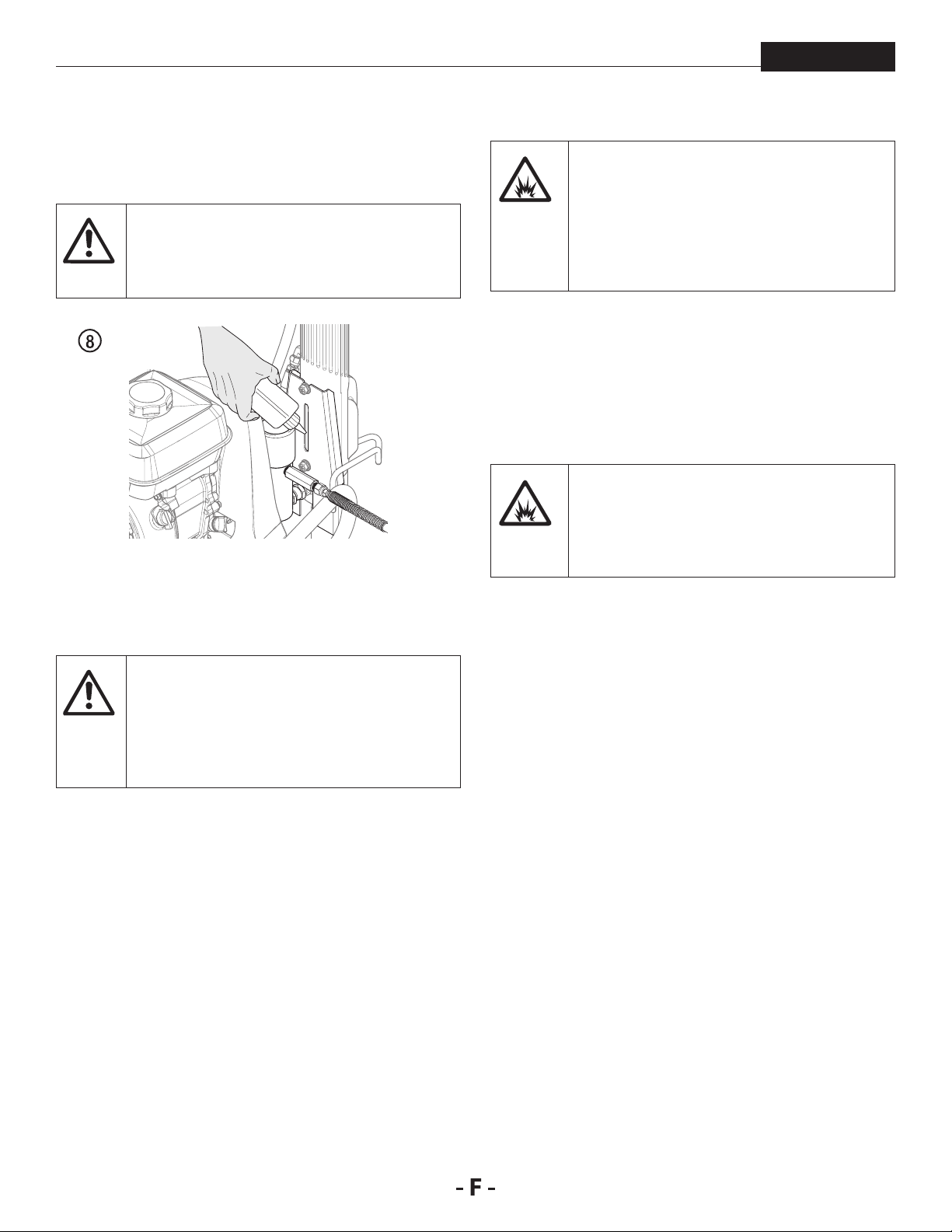
fonctionnement
At
At
4. Remplissez la coupelle d’huile à moitié avec de l’huile
Piston Lube (n° de pièce 314-480), ceci permet d’accroître
la durée de vie de l’équipement.
Piston Lube empêche l’usure prématurée des
garnitures.
tention
5. Contrôlez tous les jours le niveau de uide avant de lancer
l’appareil. Le niveau de uide hydraulique devrait toucher
le bas de la jauge. Consultez les directives d’entretien du
système hydraulique à la section Entretien du présent
manuel.
PowrBeast
Il est important de correctement relier l’appareil
à la terre. Ceci vaut aussi bien pour les modèles à
essence que les modèles électriques. Le passage
de certains matériaux dans le tuyau en nylon
produit une charge électrique statique qui peut
enammer les vapeurs de solvant lorsqu’elle est
déchargée et peut créer une explosion.
9. Filtrez toutes les peintures avec un ltre en nylon pour
un fonctionnement sans problème et pour éviter d’avoir
à nettoyer fréquemment le ltre interne et le ltre du
pistolet.
10. Vériez que la zone de vaporisation est bien ventilée
pour empêcher tout fonctionnement dangereux avec des
solvants volatiles ou des fumées d’échappement.
Si vous devez pulvériser du vernis-laque
ou d’autres produits inammables, placez
TOUJOURS le pulvérisateur à l’extérieur de l’aire
de pulvérisation, sinon, cela pourrait causer une
explosion.
11. Placez le pulvérisateur à l’extérieur de l’aire de pulvérisation
an d’éviter l’obstruction de la prise d’air du moteur ou la
surpulvérisation.
Dans le système hydraulique, vous devez
impérativement employer un liquide hydraulique
tention
6. Modèles du moteur à essence - Contrôlez tous les jours
7. Dans le cas des modèles électriques, utilisez une prise
8. Vériez que l’appareil est bien relié à la terre. Tous les
approuvé par Titan (Titan Coolo, n° de pièce 430-
361). N’utilisez aucun autre liquide hydraulique,
il pourrait gravement endommager le circuit
hydraulique et annuler la garantie.
le niveau d’huile dans le réservoir avant de démarrer
l’appareil. Le niveau d’huile du moteur à essence est
déterminé par le fabricant du moteur. Consultez le manuel
d’entretien du fabricant du moteur fourni avec ce modèle.
de courant de 15 ampères. Placez toujours le modèle
électrique de 3 à 4,5 mètres de la prise de courant. Servezvous d’un câble électrique court et d’un long tuyau de
pulvérisation. L’ajout d’une rallonge électrique diminuera
la tension. Si une rallonge est nécessaire, utilisez
uniquement une rallonge mise à la terre à trois ls no 12.
modèles sont équipés d’un œillet de mise à la terre.
Un câble de mise à la terre doit être utilisé pour relier
l’appareil à la terre. Vériez les réglementations locales sur
l’électricité pour obtenir des consignes détaillées de mise
à la terre.
78
Page 79
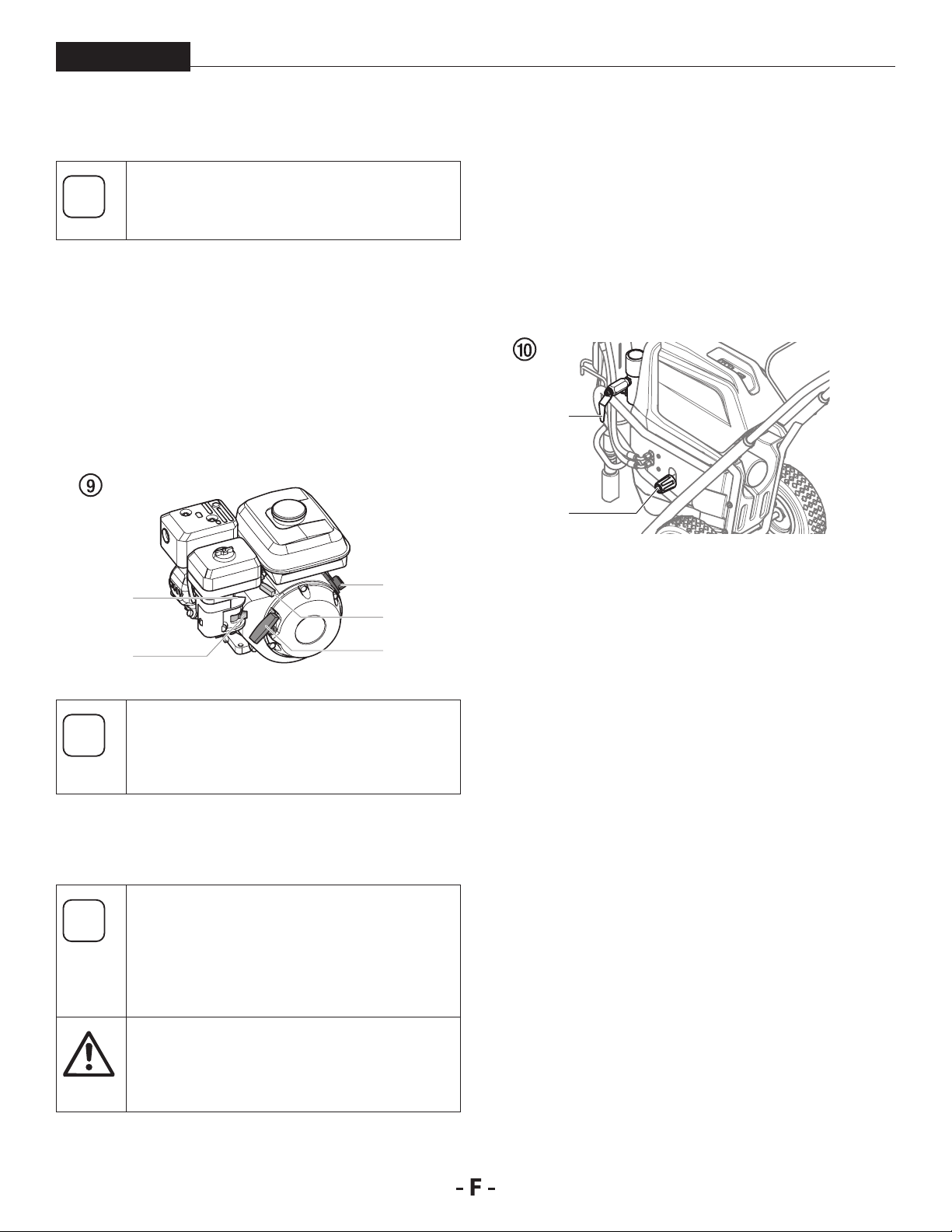
fonctionnement
i
i
i
At
PowrBeast
4.2 DÉMARRAGE DU MOTEUR MOTEUR À
ESSENCE
Suivez ces consignes chaque fois que c’est
indiqué dans le manuel pour démarrer le moteur.
1. Placez la manette de vanne de carburant (g. 9, pos. 2) en
position ouverte,
2. Placez le levier de papillon d’accélération (3) au milieu.
3. Placez le levier d’étranglement (4) en position fermée pour
un moteur froid ou en position ouverte pour un moteur
chaud.
4. Mettez la clé de contact (1) sur ON.
5. Tirez fermement sur la corde du démarreur (5) jusqu’à ce
que le moteur démarre.
1
4
3
2
Si le levier d’étrangleur (4) a été mis en position
fermée pour démarrer le moteur, il doit être
déplacé à nouveau lorsque le moteur est en
marche.
5
4.3 PRÉPARATION D’UN NOUVEAU
VAPORISATEUR
S’il s’agit d’un nouvel appareil, il est livré avec
du liquide de test dans la section des liquides
pour éviter la corrosion durant le transport et
le stockage. Ce uide doit être soigneusement
vidangé du circuit à l’aide d’essences minérales
avant de commencer à vaporiser.
Verrouillez toujours la gâchette sur le pistolet
vaporisateur pendant la préparation du circuit.
tention
Consultez les consignes du verrou de détente du
mode d’emploi du pistolet de pulvérisation.
2. Placez le
en métal.
3. Réglez la pression au minimum en tournant au maximum
le bouton de réglage de pression (g. 10, pos. 1) dans le
sens inverse des aiguilles d’une montre.
4. Ouvrez la soupape de décharge (2) en la tournant
complètement dans le sens inverse des aiguilles d’une
montre.
tuyau de décharge
dans un conteneur de déchets
2
1
5. Démarrer le moteur à essence ou moteur électrique.
a. Pour démarrer le moteur à essence, suivez les étapes à la
b. Pour démarrer le moteur électrique, poussez et
6. Tournez le bouton de réglage de pression dans le sens
7. Laissez le vaporisateur tourner pendant 15 à 30 secondes
8. Éteignez l’appareil.
a. Pour éteindre le moteur à essence :
• réglez la pression au minimum en tournant au maximum
• placez le levier de papillon d’accélération en position
• tournez l’interrupteur du moteur sur OFF.
b. An d’éteindre le moteur électrique,
• réglez la pression au minimum en tournant au maximum
• déplacez l’interrupteur pour qu’il soit en position ARRÊT.
section 4.2.
maintenez l’interrupteur à la position ON (en marche)
jusqu’à ce que le moteur électrique fonctionne à pleine
vitesse, ensuite relâchez l’interrupteur.
des aiguilles d’une montre et vers le bas d’1/3 environ
pour accroître la pression jusqu’à ce que les cycles de
vaporisation soient réguliers et que le solvant s’écoule
sans problème du tuyau de décharge.
pour vidanger le liquide de test du tuyau de vidange vers
le conteneur de déchets.
le bouton de réglage de pression dans le sens inverse
des aiguilles d’une montre,
lente, et
le bouton de réglage de pression dans le sens inverse
des aiguilles d’une montre,
1. Placez le tuyau du siphon dans un conteneur d’essences
minérales.
79
Page 80

fonctionnement
i
At
i
PowrBeast
4.4 PRÉPARATION AVANT DE PEINDRE
Avant de peindre, il est important de s’assurer
que le liquide du circuit est compatible avec la
peinture qui va être utilisée.
Les liquides et peintures incompatibles peuvent
boucher les soupapes et obliger l’utilisateur à
démonter et nettoyer la section des liquides du
vaporisateur.
Verrouillez toujours la gâchette sur le pistolet
vaporisateur pendant la préparation du circuit.
tention
1. Placez le tuyau du siphon dans un conteneur du solvant
2. Placez le tuyau de décharge dans un conteneur de déchets
3. Réglez la pression au minimum en tournant au maximum
4. Ouvrez la soupape de décharge (2) en la tournant
Consultez les consignes du verrou de détente du
mode d’emploi du pistolet de pulvérisation.
approprié.
en métal.
le bouton de réglage de pression (g. 10, pos. 1) dans le
sens inverse des aiguilles d’une montre.
complètement dans le sens inverse des aiguilles d’une montre.
• tournez l’interrupteur du moteur sur OFF.
b. An d’éteindre le moteur électrique,
• réglez la pression au minimum en tournant au maximum
le bouton de réglage de pression dans le sens inverse
des aiguilles d’une montre,
• déplacez l’interrupteur pour qu’il soit en position ARRÊT.
Assurez-vous qu’aucun embout ou protecteur
d’embout n’est installé sur le pistolet
vaporisateur.
9. Fermez la soupape de décharge en la tournant
complètement dans le sens des aiguilles d’une montre.
10. Démarrer le moteur à essence ou moteur électrique.
11. Tournez le bouton de réglage de pression dans le sens des
aiguilles d’une montre et vers le bas d’1/3 environ pour
accroître la pression.
12. Débloquez le pistolet en faisant passer la gâchette du
pistolet vers la position de déblocage.
Reliez le pistolet à la terre en le maintenant
contre le bord du conteneur en métal lors du
rinçage. Si cette précaution n’est pas respectée, il
peut se former une décharge électrique statique
pouvant à son tour provoquer un incendie.
2
1
5. Démarrer le moteur à essence ou moteur électrique.
a. Pour démarrer le moteur à essence, suivez les étapes à la
b. Pour démarrer le moteur électrique, poussez et
6. Tournez le bouton de réglage de pression dans le sens
7. Laissez le vaporisateur tourner pendant 15 à 30 secondes
8. Éteignez l’appareil.
a. Pour éteindre le moteur à essence :
• réglez la pression au minimum en tournant au maximum
• placez le levier de papillon d’accélération en position
section 4.2.
maintenez l’interrupteur à la position ON (en marche)
jusqu’à ce que le moteur électrique fonctionne à pleine
vitesse, ensuite relâchez l’interrupteur.
des aiguilles d’une montre et vers le bas d’1/3 environ
pour accroître la pression jusqu’à ce que les cycles de
vaporisation soient réguliers et que le solvant s’écoule
sans problème du tuyau de
pour vidanger le liquide de test du tuyau de vidange vers
le conteneur de déchets.
le bouton de réglage de pression dans le sens inverse
des aiguilles d’une montre,
lente, et
décharge
.
13. Déclenchez le pistolet dans le conteneur de déchets en
métal jusqu’à ce que le solvant usagé soit vidangé et que
du solvant frais sorte du pistolet.
14. Verrouillez le pistolet en tournant le verrou de la détente à
la position verrouillée (consultez le manuel du pistolet de
pulvérisation).
15. Augmentez la pression en tournant lentement et au
maximum le bouton de réglage de pression dans le sens
des aiguilles d’une montre.
16. Vériez si le système ne présente pas de fuite. En cas de
fuite, suivez la « Procédure de décharge de pression » décrite
dans ce manuel avant de serrer les raccords ou les tuyaux.
17. Suivez la « Procédure de décharge de pression » (section
4.6) décrite dans ce manuel avant de passer du solvant à
la peinture.
Assurez-vous de bien suivre la Procédure de
écharge de pression lorsque vous arrêtez
l’appareil pour une raison quelconque, y compris
lors de l’entretien ou du réglage d’une pièce du
circuit de vaporisation, du remplacement ou du
nettoyage des embouts de vaporisation, ou lors
de la préparation au nettoyage.
80
Page 81

fonctionnement
i
PowrBeast
4.5 PEINTURE
1. Placez le tuyau de siphon dans un conteneur de peinture.
2. Placez le tuyau de décharge dans un conteneur de déchets
en métal.
3. Réglez la pression au minimum en tournant au maximum
le bouton de réglage de pression (g. 10, pos. 1) dans le
sens inverse des aiguilles d’une montre.
4. Ouvrez la soupape de décharge (2) en la tournant
complètement dans le sens inverse des aiguilles d’une montre.
5. Démarrer le moteur à essence ou moteur électrique.
a. Pour démarrer le moteur à essence, suivez les étapes à la
section 4.2.
b. Pour démarrer le moteur électrique, poussez et
maintenez l’interrupteur à la position ON (en marche)
jusqu’à ce que le moteur électrique fonctionne à pleine
vitesse, ensuite relâchez l’interrupteur.
6. Tournez le bouton de réglage de pression dans le sens
des aiguilles d’une montre et vers le bas d’1/3 environ
pour accroître la pression jusqu’à ce que les cycles de
vaporisation soient réguliers et que le peinture s’écoule
sans problème du tuyau de décharge.
7. Éteignez l’appareil.
a. Pour éteindre le moteur à essence :
• réglez la pression au minimum en tournant au maximum
le bouton de réglage de pression dans le sens inverse
des aiguilles d’une montre,
• placez le levier de papillon d’accélération en position
lente, et
• tournez l’interrupteur du moteur sur OFF.
b. An d’éteindre le moteur électrique,
• réglez la pression au minimum en tournant au maximum
le bouton de réglage de pression dans le sens inverse
des aiguilles d’une montre,
• déplacez l’interrupteur pour qu’il soit en position ARRÊT.
8. Démontez le tuyau de purge du conteneur de déchets et
placez-le dans le conteneur de peinture.
9. Fermez la vanne de purge en la tournant au maximum,
dans le sens des aiguilles d’une montre.
10. Démarrer le moteur à essence ou moteur électrique.
11. Tournez le bouton de réglage de pression dans le sens des
aiguilles d’une montre et vers le bas d’1/3 environ pour
accroître la pression.
12. Débloquez le pistolet en faisant passer la gâchette du
pistolet vers la position de déblocage.
Reliez le pistolet à la terre en le maintenant
contre le bord du conteneur en métal lors du
rinçage. Si cette précaution n’est pas respectée, il
peut se former une décharge électrique statique
pouvant à son tour provoquer un incendie.
13. Déclenchez le pistolet dans le conteneur de déchets en
métal jusqu’à ce que le solvant et l’air soient vidangés et
que de la peinture sorte du pistolet.
14. Bloquez le pistolet en faisant passer la gâchette du pistolet
vers la position de blocage (g. 10).
15. Éteignez l’appareil.
16. Fixez la protection d’embout au pistolet comme indiqué
sur la protection d’embout ou sur les manuels d’embouts.
81
17. Démarrer le moteur à essence ou moteur électrique.
18. Augmentez la pression en tournant lentement le bouton
de réglage de la pression dans le sens des aiguilles d’une
montre et testez la forme de vaporisation sur un bout de
carton. Ajustez le bouton de réglage de pression jusqu’à
ce que le pistolet soit complètement atomisé.
4.6 PROCÉDURE DE DÉCHARGE DE PRESSION
1. Bloquez le pistolet en faisant passer la gâchette du pistolet
vers la position de blocage.
2. Éteignez l’appareil.
a. Pour éteindre le moteur à essence :
• réglez la pression au minimum en tournant au maximum
• placez le levier de papillon d’accélération en position lente,
• tournez l’interrupteur du moteur sur OFF.
b. An d’éteindre le moteur électrique,
• réglez la pression au minimum en tournant au maximum
• déplacez l’interrupteur pour qu’il soit en position ARRÊT.
3. Débloquez le pistolet en faisant passer la gâchette du
pistolet vers la position de déblocage (consultez le manuel
du pistolet de pulvérisation).
4. Maintenez fermement la partie métallique du pistolet
contre un conteneur de déchets en métal pour décharger
l’électricité statique du pistolet.
5. Enclenchez le pistolet pour éliminer toute pression
résiduelle dans le tuyau.
6. Bloquez le pistolet en faisant passer la gâchette du pistolet
vers la position de blocage.
7. Placez le tuyau de
en métal.
8. Ouvrez la vanne de purge en la tournant au maximum
dans le sens contraire des aiguilles d’une montre.
RISQUE ÉVENTUEL D’INJECTION. Ne vaporisez
pas si la protection d’embout n’est pas montée.
Ne déclenchez jamais le pistolet si l’embout
n’est pas en position de vaporisation ou
débouché. Engagez toujours le verrouillage de
la gâchette du pistolet avant de démonter, de
remplacer ou de nettoyer l’embout.
Si vous augmentez la pression au-delà de la
pression nécessaire pour atomiser la peinture,
vous pouvez provoquer une usure prématurée
des embouts et une vaporisation excessive.
Assurez-vous de bien suivre la procédure de
décharge de pression lorsque vous arrêtez
l’appareil pour une raison quelconque, y compris
lors de l’entretien ou du réglage d’une pièce du
circuit de vaporisation, du remplacement ou du
nettoyage des embouts de vaporisation ou lors
de la préparation au nettoyage.
le bouton de réglage de pression dans le sens inverse
des aiguilles d’une montre,
le bouton de réglage de pression dans le sens inverse
des aiguilles d’une montre,
décharge
dans un conteneur de déchets
Page 82

pulvérisation
i
i
5 PULVÉRISATION
PowrBeast
Risque d’injection. Ne pulvérisez pas sans
avoir installé au préalable le protège-embout.
N’appuyez JAMAIS sur la gâchette du pistolet
si l’embout n’est pas sur la position de
pulvérisation ou de débouchage. Bloquez
toujours la gâchette du pistolet avant d’enlever,
de remplacer ou de nettoyer l’embout.
A) Le secret pour réaliser un bon travail de peinture est
d’appliquer une couche homogène sur toute la surface.
Déplacez votre bras à une vitesse constante et maintenez
le pistolet de pulvérisation à une distance régulière de
la surface. La meilleure distance de pulvérisation entre
l’embout et la surface est de 25-30 cm.
A
25 - 30 cm
C
25 - 30 cm25 - 30 cm
Si les bords de projection sont trop nets ou s’il y
a des bandes dans le jet, il faut soit augmenter
la pression de projection soit diluer davantage le
produit.
5.1 NETTOYAGE D’UNE BUSE OBSTRUÉE
Si la répartition de la pulvérisation devient
déformée ou s’arrête complètement en appuyant
sur la détente, suivre les étapes ci-dessous.
B) Maintenez le pistolet de pulvérisation à angle droit par
rapport à la surface. Pour ce faire, vous devez faire des
allers-retours avec tout le bras au lieu de simplement plier
le poignet.
Maintenez le pistolet de pulvérisation perpendiculaire
à la surface pour que la couche ne soit pas plus épaisse
d’un côté que de l’autre.
B
C) Actionnez le pistolet après avoir commencé le passage.
Relâchez la gâchette avant la n du passage. Le pistolet
pulvérisateur doit être en mouvement au moment
d’appuyer sur la gâchette ou de la relâcher. Faites
chevaucher les passages sur environ 30 %, pour garantir
une couche uniforme.
1. Ouvrir la vanne de décharge à la position PRIME (k
circulation).
2. Si la buse est obstruée, faites tourner la poignée de la
buse à 180° jusqu’à ce que la èche gurant sur la poignée
indique l’opposé de la direction de pulvérisation et que la
poignée s’enclenche en position inversée (g. 12).
3. Fermer la vanne de décharge, position SPRAY (p
projection).
4. Appuyez une fois sur la détente du pistolet pour que la
pression débouche la buse. N’appuyez JAMAIS deux fois
de suite sur la détente lorsque la buse est dans la position
inversée. Cette procédure peut être répétée jusqu’à ce
que la buse ne soit plus obstruée.
Le ux sortant de la buse de pulvérisation est
à très forte pression. Tout contact avec une
quelconque partie du corps peut s’avérer
dangereux. Ne mettez pas de doigt sur l’embout
du pistolet. Ne visez personne avec le pistolet.
N’utilisez jamais le pistolet pulvérisateur sans
disposer du protège-embout approprié.
82
Page 83

pulvérisation
i
i
At
i
i
i
i
i
PowrBeast
5.2 INTERRUPTIONS DE TRAVAIL
Suivez ces étapes si vous arrêtez de pulvériser
pendant jusqu’à 20 heures. Suivez ces étapes
seulement si vous avez utilisé des produits à
pulvériser au latex ou à l’eau.
Si vous remplacez tout simplement le récipient
de produit, tournez le bouton de commande de
pression complètement dans le sens contraire
des aiguilles d’une montre au minimum avant de
changer le récipient de produit.
Tournez le bouton de commande de pression
dans le sens des aiguilles d’une montre à la
position précédente lorsque vous êtes prêt à
recommencer la pulvérisation.
1. Suivez la « Procédure de décharge de pression » décrite au
paragraphe Fonctionnement de ce manuel (section 4.6).
2. Placez le pistolet de pulvérisation dans un sac en plastique,
ou déposez-le dans un seau d’eau.
3. Laissez le tube d’aspiration et le tuyau de retour immergés
dans le matériau de revêtement ou immergez-les dans un
agent de nettoyage correspondant.
4. Recouvrez le matériau de revêtement de plastique et
placez l’appareil dans un endroit frais et ombragé pour
empêcher le matériau de s’assécher.
Lors de la mise en œuvre de peintures à séchage
rapide ou d’un produit à deux composants,
tention
rincer sans faut le groupe à l’intérieur du temps
d’utilisation avec le produit de nettoyage
adéquat.
5.3 MANIPULATION DU FLEXIBLE À HAUTE
PRESSION
L’appareil est muni d’un tuyau à haute pression
conçu spécialement pour les pompes sans air.
Ne jamais utiliser un exible défectueux. Danger
de blessure!
Ne jamais essayer de réparer un exible
endommagé!
Le tuyau exible haute pression doit être traité avec soin. Il faut
éviter de trop plier le exible; le plus petit rayon ne doit pas être
inférieur à 20 cm.
Protéger le exible contre le passage de véhicules et éviter le
frottement sur des arêtes vives.
Ne jamais tirer sur le exible à haute pression pour déplacer
l‘appareil.
Faire attention à ne pas tordre le exible à haute pression. Cela
peut être évité en utilisant un pistolet pulvérisateur de Wagner
avec une articulation pivotante et un dévidoir de tuyau.
Pour la manipulation du tuyau exible haute
pression lors de travaux sur un échafaudage,
il s‘est avéré comme le plus avantageux de
toujours laisser le tuyau exible du côté extérieur
de l’échafaudage.
Le risque d‘endommagements s‘accroît dans
le cas des vieux exibles à haute pression. Titan
recommande de remplacer le exible à haute
pression au bout de 6 ans.
Lorsque vous êtes à nouveau prêt à pulvériser,
enlevez le plastique du récipient de matériau et
redémarrez le pulvérisateur en suivant les étapes
décrites à la section 4.4.
83
Pour des raisons de fonctionnement, de sécurité
et de durée de vie, utiliser exclusivement des
tuyaux exibles à haute pression d‘origine de
Titan.
Page 84

nettoyage
At
At
i
At
Attention
PowrBeast
6 NETTOYAGE
Le pulvérisateur, le tuyau et le pistolet doivent
être soigneusement nettoyés tous les jours après
tention
6.1 CONSIGNES SPÉCIALES DE NETTOYAGE
• Rincez toujours le pistolet pulvérisateur de préférence
à l’extérieur et au moins à une longueur de tuyau de la
pompe de pulvérisation.
• Si vous recueillez les solvants vidangés dans un conteneur
en métal d’un gallon (environ 3,780 litres), placez celui-ci
dans un conteneur vide de 5 gallons (environ 19 litres),
puis vidangez les solvants.
• La zone doit être totalement débarrassée de vapeurs
inammables.
• Respectez toutes les consignes de nettoyage.
utilisation. Le non-respect de ces consignes peut
mener à une agglutination du matériau et donc
considérablement endommager la performance
de l’appareil.
Lorsque vous utilisez des essences minérales ou
tout autre solvant pour nettoyer le vaporisateur,
le tuyau ou le pistolet, vaporisez toujours à la
pression minimale avec l’embout du pistolet
démonté. L’accumulation d’électricité statique
peut entraîner un incendie ou une explosion en
présence de vapeurs inammables.
LORS DE L’UTILISATION AVEC DES
SOLVANTS INFLAMMABLES
7. Démarrer le moteur à essence ou moteur électrique.
8. Laissez le solvant circuler dans l’appareil et vidangez
la peinture par le tuyau de purge dans le conteneur de
déchets en métal.
9. Arrêter le matériel OFF (ARRET).
10. Fermez la vanne de purge en la tournant au maximum,
dans le sens des aiguilles d’une montre.
11. Démarrer le moteur à essence ou moteur électrique.
Reliez le pistolet à la terre en le maintenant
contre le bord du conteneur en métal lors du
rinçage. Si cette précaution n’est pas respectée, il
peut se former une décharge électrique statique
pouvant à son tour provoquer un incendie.
12. Déclenchez le pistolet dans le conteneur de déchets en
métal jusqu’à ce que la peinture soit vidangée et que du
solvant sorte du pistolet.
13. Continuez à déclencher le pistolet dans le conteneur de
déchets en métal jusqu’à ce que le solvant sortant du
pistolet soit propre.
Pour un stockage prolongé ou dans des
conditions climatiques froides, pompez de
l’essence minérale dans tout le circuit.
14. Suivez la « Procédure de décharge de pression » décrite au
paragraphe Fonctionnement de ce manuel.
15. Conservez l’outil dans un endroit sec et propre.
6.2 NETTOYAGE DU PULVÉRISATEUR
1. Suivez la « Procédure de décharge de pression » décrite au
paragraphe Fonctionnement de ce manuel (section 4.6).
2. Démontez l’embout du pistolet et la protection d’embout
puis procédez au nettoyage en utilisant une brosse et un
solvant approprié.
3. Placez le tuyau du siphon dans un conteneur du solvant
approprié.
Utilisez des solvants compatibles lors du
nettoyage de peintures laquées, de laques, de
tention
4. Placez le tuyau de
5. Réglez la pression au minimum en tournant au maximum
6. Ouvrez la vanne de purge (3) en la tournant au maximum,
peinture à base de brai et d’époxy. Vériez auprès
du fabricant du liquide le solvant recommandé
pour ce liquide.
décharge
en métal.
le bouton de réglage de pression dans le sens inverse des
aiguilles d’une montre.
dans le sens contraire des aiguilles d’une montre.
dans un conteneur de déchets
Ne stockez pas l’appareil sous pression.
tention
6.3 NETTOYAGE EXTÉRIEUR DU GROUPE
Modèles électriques - Assurez-vous que le
cordon d’alimentation est débranché pour éviter
un choc électrique.
Danger de court-circuit par la pénétration d’eau!
Ne jamais utiliser un jet ou de la vapeur sous
pression pour le nettoyage.
Ne pas placer le exible à haute pression dans du
solvant. Essuyer l‘extérieur uniquement avec un
chion imprégné.
Nettoyer l’extérieur du groupe à l’aide d’un chion imbibé du
produit de nettoyage adéquat.
84
Page 85

nettoyage
i
i
PowrBeast
6.4 NETTOYAGE DE LA CRÉPINE
Des ltres propres assurent toujours un débit
maximum, une pression de projection constante
ainsi qu’un fonctionnement correct du matériel.
SYSTÈME D’ASPIRATION SUBMERSIBLE
1. La crépine s’obstrue et doit être nettoyée au moins une
fois par jour.
2. Retirer l’anneau de retenue (g. 13, article 1) du logement
de clapet de pied (2).
3. Retirer la crépine d’aspiration (3) du logement de clapet
de pied (2).
4. Nettoyez-le soigneusement avec le solvant adéquat.
2
3
6.5 NETTOYAGE DU PISTOLET AIRLESS
1. Rincer le pistolet Airless à faible pression de service avec le
produit de nettoyage adéquat.
2. Nettoyer soigneusement la buse avec le produit adéquat
de manière à éliminer les restes de produit.
3. Nettoyer soigneusement l’extérieur du pistolet.
Nettoyez le pistolet de pulvérisation après
chaque utilisation.
TAMIS DE CROSSE DANS LE PISTOLET AIRLESS FIG. 15
1. Détachez le dessus du pontet (1) de la tête du pistolet.
2. En se servant de la partie inférieure du pontet comme clé,
desserrez et enlevez l’ensemble de la poignée (2) de la tête
du pistolet.
3. Extrayez le ltre (3) usagé de la tête du pistolet. Nettoyez
ou remplacez.
4. Faites glisser le nouveau ltre, la partie letée en premier,
dans la tête du pistolet.
5. Placez le joint de la poignée dans la tête du pistolet avec la
partie plate du joint vers la tête du pistolet. Serrez à l’aide
de la clé de la détente.
6. Enclenchez à nouveau le pontet sur la tête du pistolet.
1
SYSTÈME D’ASPIRATION STANDARD
1. Dévisser la crépine (g. 14) du tube d’aspiration.
2. Nettoyer ou remplacer la crépine.
Eectuer le nettoyage à l’aide d’un pinceau dur et d’un
produit de nettoyage correspondant.
1
85
3
2
Page 86

entretien
i
i
i
7 ENTRETIEN
PowrBeast
Avant de continuer, suivez la procédure de
réduction de pression précédemment exposée
dans ce manuel. Respectez également tous
les autres avertissements an de minimiser les
risques de blessures dus à des projections ou à
des pièces mobiles ou les risques de décharge
électrique. Débranchez toujours le pulvérisateur
avant de procéder à son entretien !
7.1 ENTRETIEN QUOTIDIEN
Deux procédures quotidiennes sont requises an de procéder à
l’entretien régulier de ce pulvérisateur.
A. Lubrication des garnitures supérieures (section 7.2).
B. Nettoyage de la crépine (section 6.4).
7.2 LUBRIFICATION DES GARNITURES
SUPÉRIEURES
1. Ôtez la peinture qui a coulé derrière les garnitures
supérieures dans le collecteur d’huile (g. 16, pos. 1) situé
au-dessus de la section des liquides.
2. Remplissez le collecteur d’huile à moitié avec de l’huile
Piston Lube (n° de pièce 314-480) fournie par le fabricant.
Cela permet d’accroître la durée de vie de l’équipement.
7.3 ENTRETIEN DU FILTRE
Nettoyez régulièrement le ltre. Les ltres
sales ou obstrués peuvent réduire de manière
considérable la capacité ltrante de l’appareil et
occasionner un certain nombre de problèmes
dans le système (faible pulvérisation, buses
obstruées, etc).
NETTOYAGE FIG. 17
Pour nettoyer le ltre, veuillez suivre la procédure qui suit :
1. Suivez la « Procédure de décharge de pression » décrite au
paragraphe Fonctionnement du présent manuel.
2. Ôte le bouchon (1) et le ressort (2) du ltre.
3. Ôtez l’élément à bille (3) du ltre par le haut du corps du
ltre (4).
4. Nettoyez à l’intérieur du corps du ltre, l’élément à bille et
le bouchon au moyen d’un solvant approprié.
1
2
1
Ne remplissez pas trop le collecteur d’huile de
façon à éviter que l’huile ne déborde et ne se
déverse dans la peinture.
3
7
8
5
6
4
Manipulez les pièces avec soin car toute impureté,
saleté, rayure ou encoche peut empêcher les
joints toriques ou les joints d’adhérer.
Cet élément ltre depuis l’intérieur vers
l’extérieur. Veillez à nettoyer soigneusement
l’intérieur de l’élément du ltre. Trempez-le dans
le solvant de manière à ramollir la peinture sèche
ou remplacez-le.
86
Page 87

entretien
i
i
i
At
i
i
PowrBeast
INSPECTION FIG. 17
Inspectez toutes les pièces du ltre avant de le remonter.
1. Inspectez la bille à l’intérieur de l’élément du ltre. Si
la bille présente des coupures ou des rayures liées à la
pression, remplacez l’élément du ltre.
a. Si la bille est coupée, retirez le joint torique en PTFE (5) à
l’aide d’un extracteur de joint torique et retirez le siège
en carbure (6).
b. Vériez que le siège ne comporte ni encoches ni
rainures. Si le siège est endommagé, remplacez-le.
Si vous le retirez, le joint torique en PTFE sera
endommagé et devra être remplacé.
2. Retirez le ressort (2) de son guide situé dans le bouchon
du ltre.
a. Mesurez la longueur du ressort non compressé. S’il
mesure moins de 1,9 cm (3/4”) d’une extrémité à l’autre,
remplacez-le.
b. Poussez le ressort dans son guide an qu’il s’enclenche à
sa place.
3. Inspectez les deux joints en PTFE (7,8) et le joint torique
en PTFE (5) an de détecter toute éventuelle déformation,
encoche ou coupure. Le cas échéant, remplacez-les.
7.4 ENTRETIEN DU SYSTÈME HYDRAULIQUE
Dans le système hydraulique, vous devez
impérativement employer un liquide
tention
1. Vériez le liquide uide hydraulique tous les jours. Le
hydraulique approuvé par Titan (Titan Coolo,
n° de pièce 430-361). N’utilisez aucun autre
uide hydraulique. L’emploi de tout autre uide
hydraulique risque de gravement endommager
le système hydraulique et annulera la garantie.
niveau de uide hydraulique devrait toucher le bas de la
jauge (1). Si le bout est sec, ajoutez du uide hydraulique
Coolo™ de Titan (no de pièce 430-361) uniquement.
N’ajoutez ni ne changez le uide hydraulique si vous n’êtes
pas dans un lieu propre dénué de poussière. La pollution
du uide hydraulique diminue la durée de vie de la pompe
hydraulique et annule la garantie.
Assurez-vous de placer l’appareil sur une surface
plate au moment de vérier le niveau de uide
hydraulique.
Les joints en PTFE, le joint torique en PTFE et le
ressort sont inclus dans le Kit de maintenance du
ltre n° de pièce 930-050.
2
1
REMONTAGE FIG. 16
Après avoir nettoyé et inspecté toutes les pièces, rassemblez
le ltre.
1. Placez le siège en carbure (6) dans le corps du ltre (4).
Assurez-vous que le côté biseauté du siège est dirigé vers
le haut.
2. Placez le joint torique en PTFE (5) dans la rainure du
diamètre extérieur du siège en carbure (6).
3. Placez l’élément à bille (3) dans le corps du ltre (4).
Le haut et le bas de l’élément à bille sont
identiques.
4. Si ce n’est déjà fait, poussez le ressort (2) dans son
guide situé dans le bouchon du ltre (1) jusqu’à ce qu’il
s’enclenche à sa place.
5. Placez le joint en PTFE (8) n sur le pas en haut du corps
du ltre (4).
6. Placez le joint en PTFE (7) épais sur le joint n (8).
7. Serrez le bouchon du ltre (1) au corps du ltre (4).
87
2. Changez le uide hydraulique tous les douze mois. Drainez
3. Le système hydraulique est doté d’un ltre hydraulique
4. L’entretien de la pompe hydraulique ne doit pas s’eectuer
3
l’ancien uide du réservoir et remplissez-le de 5,9 litres
de uide hydraulique. Faites marcher le pulvérisateur à
une pression susante pour faire fonctionner la section
des liquides. Faites tourner le pulvérisateur à basse
pression pendant 5 minutes. Cela permet d’évacuer l’air
du système. Vériez le niveau du uide au terme de cette
procédure. Ne remplissez pas trop le réservoir.
Lorsque vous remplacez le ltre hydraulique (3)
au cours du changement de uide, il peut s’avérer
utile d’ajouter jusqu’à un litre supplémentaire de
uide hydraulique.
externe remplaçable. Changez le ltre tous les douze mois.
sur place. Si l’entretien de la pompe hydraulique est
nécessaire, la pompe doit être retournée à un centre de
services Titan autorisé.
Page 88

entretien
At
i
PowrBeast
7.5 ENTRETIEN DE LA SECTION DES FLUIDES
Si le pulvérisateur doit ne pas être utilisé pendant une longue
période, il est conseillé, suite au nettoyage, d’introduire un
mélange de kérosène et huile faisant oce de conservateur. Les
garnitures tendent à sécher lorsqu’elles ne sont pas utilisées.
Cela s’applique notamment à l’ensemble des garnitures
supérieures pour lesquelles il est recommandé de recourir à
Piston Lube (n° de pièce 314-480) pour une utilisation normale.
Si le pulvérisateur n’a pas été utilisé pendant une longue
période, il peut s’avérer utile d’amorcer la pompe avec un
solvant. Il est extrêmement important que les lets du raccord
du tuyau d’aspiration soient correctement xés. Toute fuite
d’air pourrait occasionner un fonctionnement irrégulier du
pulvérisateur et pourrait endommager le système. Les courses
ascendantes et descendantes doivent être approximativement
similaires en terme de temps (l’une ne doit pas être plus rapide
que l’autre). Une course ascendante ou descendante trop
rapide pourrait indiquer la présence d’air dans le système
ou un mauvais fonctionnement de la soupape ou des sièges
(reportez-vous à la section consacrée au dépannage).
7.6 TUYAU FLEXIBLE HAUTE PRESSION
Contrôler visuellement le tuyau exible haute pression pour
entailles ou bosses éventuellement présentes, en particulier à la
transition dans le raccord. Les écrous-raccords doivent pouvoir
tourner librement. Une conductibilité inférieure à 1 mégohm
doit être présente sur toute la longueur.
Faire eectuer tous les contrôles électriques par
le service après-vente de Titan.
tention
Le risque d‘endommagements s‘accroît dans le
cas des vieux exibles à haute pression.
Titan recommande de remplacer le exible à
haute pression au bout de 6 ans.
88
Page 89

entretien
PowrBeast
7.7 ENTRETIEN DE BASE DU MOTEUR MOTEUR
À ESSENCE
• Pour obtenir des informations détaillées sur l’entretien du
moteur ou des spécications techniques, reportez-vous au
deuxième manuel du moteur à essence.
• Tout entretien du moteur doit être réalisé par un revendeur
agréé par le fabricant du moteur.
• Utilisez une huile pour moteur de qualité premium. Il est
conseillé d’utiliser la 10W30 pour une utilisation générale
quelque soit la température. D’autres viscosités peuvent
être requises sous d’autres climats.
• Utilisez uniquement une bougie d’allumage (NGK) BR-6HS.
Ecartez les électrodes de 0,028 à 0,031 pouces (de 0,7 à 0,8
mm). Utilisez toujours une clé à bougie.
TOUS LES JOURS
1. Vériez le niveau d’huile du moteur et remplissez le
réservoir si besoin est.
2. Vériez le niveau d’essence du moteur et remplissez le
réservoir si besoin est.
Suivez toujours la procédure de ravitaillement
précédemment exposée dans ce manuel.
FONCTIONNEMENT ET ENTRETIEN DU MOTEUR
• Nettoyez les ltres à air et à huile du moteur à essence
toutes les 25 heures ou une fois par semaine. Ne laissez
pas la peinture ou les saletés s’accumuler sur la grille
d’entrée d’air du volant du moteur à essence. Nettoyezla régulièrement. La durée de vie et l’ecacité du moteur
à essence dépend de son bon entretien. Changez l’huile
du moteur toutes les 100 heures. Tout manquement à ces
consignes peut occasionner une surchaue du moteur.
Consultez le manuel d’entretien qui vous est fourni par le
fabricant du moteur.
• Pour économiser de l’essence et accroître la durée de vie
et l’ecacité du pulvérisateur, faites fonctionner le moteur
à essence au régime moteur le plus bas lui permettant de
tourner sans forcer et de fournir la quantité de peinture
requise. Un régime moteur plus élevé n’est pas synonyme
de pression de travail plus grande. Le moteur à essence est
relié à la pompe hydraulique par le biais d’une association
de poulies destinées à fournir un maximum de peinture à
un régime moteur maximum.
• La garantie sur les moteurs à essence se limite au fabricant
d’origine.
LES 20 PREMIÈRES HEURES
• Changez l’huile du moteur.
TOUTES LES 100 HEURES
• Changez l’huile du moteur.
• Nettoyez le collecteur de dépôt.
• Nettoyez et re-réglez la bougie d’allumage.
• Nettoyez le pare-étincelles.
TOUTES LES SEMAINES
• Retirez le couvercle du ltre à air et nettoyez l’élément.
Dans les environnements très poussiéreux, vériez le ltre
quotidiennement. Remplacez l’élément le cas échéant.
Les pièces de rechange peuvent être achetées auprès de
votre revendeur local du fabricant de moteur.
89
Page 90

entretien
At
i
i
PowrBeast
7.8 ENTRETIEN DU MOTEUR HYDRAULIQUE
L’entretien du moteur hydraulique doit
uniquement s’opérer dans un lieu propre,
tention
1. Tournez le bouton de commande de pression
2. Avec la section des liquides immergée dans un seau d’eau,
3. Tournez le bouton de commande de pression dans le sens
4. Une fois que la pompe est amorcée, tournez la soupape de
5. En regardant la course du piston par la fenêtre à l’arrière
6. Éteignez le moteur ou le moteur électrique.
7. Continuez en suivant les étapes suivantes.
dénué de toute poussière. Toute poussière
ou particule métallique laissée dans le moteur
ou s’y introduisant lors du remontage peut
endommager les pièces critiques et aecter la
durée de vie et la garantie de l’appareil. Toutes
les pièces doivent être inspectées an d’assurer
une propreté absolue.
Pour l’entretien du moteur hydraulique, il est
recommandé que le piston soit au milieu de sa
course. Suivez les étapes ci-dessous.
complètement dans le sens contraire des aiguilles d’une
montre au paramètre le plus faible.
démarrez le moteur ou allumez le moteur électrique.
des aiguilles d’une montre de 1 à 2 tours complets.
sûreté à SPRAY (pulvérisation).
du moteur/de la pompe et en utilisant la plus petite buse
disponible (pour la vitesse du piston la plus lente possible),
pulvérisez l’eau dans le seau (ou autre récipient à déchets).
Arrêtez de pulvériser lorsque le piston est à la position
souhaitée.
1
2
3. À l’aide d’une seringue ou d’une éponge, absorbez le
uide hydraulique excédentaire dans la cavité laissée par
l’enlèvement de la che de la tête du cylindre.
4. Dans la zone d’accès laissée par l’enlèvement de l’ensemble
de la carte PCB, situez les côtés plats sur la partie inférieure
du piston hydraulique (g. 24, article 3). Placez une clé sur
les côtés plats du piston hydraulique.
5. Glissez l’anneau de retenue (4) sur le coupleur du piston (5)
vers le haut pour dégager les trous du coupleur.
6. Insérez soigneusement un tournevis dans un des trous
libres du coupleur du piston (5) pour le xer.
Il se peut que vous deviez tourner l’ensemble
du piston hydraulique (4) et le coupleur (5)
légèrement avec la clé pour avoir accès à l’un des
trous libres.
DÉMONTAGE DU MOTEUR HYDRAULIQUE
1. À l’aide d’une clé hexagonale, desserrez les vis imperdables
qui xent l’ensemble de la carte PCB (g. 23, article 1) au
vérin du moteur hydraulique. Une fois enlevée, la carte
peut pendre de son cordon.
2. Enlevez le bouchon mâle de la culasse (2) du vérin du
moteur hydraulique.
7. Desserrez le piston hydraulique (4) du coupleur (5) à l’aide
de la clé sur les côtés plats du piston hydraulique (4).
4
5
3
90
Page 91

entretien
i
At
i
i
PowrBeast
8. Vissez légèrement une vis 1/4 - 20 dans le dessus du piston
hydraulique (g. 25, article 4). À l’aide de la vis, tirez le
piston du dessus du vérin du moteur hydraulique.
9. Enlevez soigneusement le joint d’étanchéité (6) et la bague
d’usure (7) du piston. Remplacez-les par de nouvelles
pièces de la trousse.
Assurez-vous d’enduire le nouveau joint
d’étanchéité et la nouvelle bague d’usure d’huile
hydraulique avant de les installer.
6
4
Enlevez très soigneusement ces pièces.
N’égratignez pas la surface en métal de
tention
12. Trempez les nouvelles pièces de la trousse dans l’huile
REMONTAGE DU MOTEUR HYDRAULIQUE
1. Replacez l’ensemble de la che (8) à l’intérieur du vérin du
l’ensemble de la che.
hydraulique et installez-les sur la che.
11
10
9
moteur hydraulique. Serrez-le avec la clé hexagonale en
forme de L.
11
10
9
7
10. À l’aide d’une clé hexagonale en forme de L, dévissez
l’ensemble de la che (g. 26, article 8) de l’intérieur du
vérin du moteur hydraulique.
8
11. Enlevez soigneusement la bague d’usure (g. 27, article
9), le joint torique (10) et la coupelle d’étanchéité avec un
joint torique (11) de la che.
Inspectez le fond du piston hydraulique pour
détecter d’éventuelles parties tranchantes qui
pourraient endommager le joint d’étanchéité du
piston (11) pendant la réinstallation.
2. Replacez le piston hydraulique (4) sur le dessus du vérin du
moteur hydraulique. À l’aide d’un maillet en caoutchouc,
tapez soigneusement sur le piston pour l’insérer dans le
cylindre jusqu’à ce que les côtés plats soient visibles dans
la zone d’accès au-dessus du coupleur du piston (5).
3. Enlevez la vis 1/4 - 20 du dessus de l’ensemble du piston.
4. En utilisant un tournevis dans le trou libre du coupleur du
piston (5) et une clé sur les côtés plats du piston hydraulique
(4), xez à nouveau les deux pièces et serrez-les.
5. Glissez en place l’anneau de retenue sur le coupleur.
6. Replacez la che de la tête du cylindre (2).
7. Replacez l’ensemble de la carte PCB (1).
Une fois que la réparation est terminée,
démarrez le moteur ou le moteur électrique.
Laissez l’appareil fonctionner pendant quelques
minutes et arrêtez-le.
Vériez immédiatement le niveau d’huile
hydraulique et remplissez l’appareil, au besoin.
91
Page 92

entretien
At
7.9 MAINTENANCE DE LA SECTION DES LIQUIDES
PowrBeast
POWRBEAST 4700 / POWRBEAST 4700T
1
2
29
4a
6
5
3
8
4700
7
9
23
26
4b
10
11
12
13
27
30
14
15
31
16
17
18
19
20
21
22
23
24
25
POWRBEAST 7700 / POWRBEAST 9700
1
2
30
4a
5
3
6
8
9
4b
28
10
11
12
13
14
15
31
16
17
18
19
20
21
22
23
24
25
tention
L’utilisation de pièces de rechange autres que celles
fournies pas Titan peut entraîner l’annulation de la
garantie. Demandez des pièces d’origine de Titan
pour une meilleure maintenance. Ces pompes
doivent être régulièrement entretenues après 1 000
heures d’utilisation environ. Un entretien précoce
est nécessaire s’il y a des fuites importantes dans
la garniture supérieure ou si la course ascendante
ou descendante de la pompe devient trop rapide.
L’utilisation du lubriant Piston Lube de Titan (n° de
pièce 314-480) est conseillée pour lubrier la garniture
supérieure. Ne remplacez pas ce lubriant par de
l’huile, de l’eau ou un solvant pour lubrier la garniture
supérieure.
2. Faites glisser la bague de retenue (1) vers le haut au moyen d’un
petit tournevis puis extrayez la goupille de connexion (2).
3. PowrBeast 4700 - Enlevez le tube-siphon (26).
4. Tournez l’écrou d’enlèvement (15) de la section des liquides dans
le sens contraire des aiguilles d’une montre an qu’il atteigne son
point le plus bas sur le letage du vérin (16).
5. Placez une clé sur les côtés plats de l’écrou d’enlèvement de la
section des liquides (15). Tournez la clé dans le sens contraire des
aiguilles d’une montre pour desserrer l’ensemble de la section
des liquides.
6. Tirez soigneusement la section des liquides vers le bas pour
enlever le moteur hydraulique.
7. Pour procéder à l’entretien de la section des liquides, stabilisez-la
DÉMONTAGE DE LA SECTION DES LIQUIDES
1. À l’aide d’une clé hexagonale, desserrez les vis imperdables qui
xent l’ensemble de la carte PCB (g. 27, article 30) au vérin du
moteur hydraulique. Une fois enlevée, la carte peut pendre de
son cordon.
en plaçant les côtés plats de l’écrou d’enlèvement de la section
des liquides (15) dans un étau.
8. Dévissez le logement du clapet de pied (23) avec une clé à sangle.
9. Retirez le ressort de garniture supérieure (5) et la garniture
supérieure (4a) du bloc moteur/pompe.
92
Page 93

entretien
i
i
i
i
PowrBeast
10. Placez une clé sur les côtés plats sur le dessus de la tige de
déplacement (6). À l’aide d’une seconde clé, desserrez et
enlevez le logement de la soupape de sortie (13) de la tige de
déplacement (6).
11. Enlevez la rondelle d’étanchéité (12), le siège de la soupape
de sortie (11), la bille de la soupape de sortie (10), la cage de
la soupape de sortie (28, PowrBeast 7700 / PowrBeast 9700
uniquement), la garniture inférieure (4b), le ressort de garniture
inférieure (9) et la bague de retenue du ressort (8).
12. À l’aide d’une rallonge de 1,25 cm xée à une clé à cliquet de 1,25
cm, insérez le bout de la rallonge dans l’ouverture carrée de la
cage du clapet de pied (17) à l’intérieur du logement du clapet
de pied (23). Dévissez et enlevez la cage du clapet de pied du
logement du clapet de pied.
13. Retirez le joint torique en PTFE (22), la bille du clapet de pied (18),
le siège du clapet de pied (19) et le joint torique du siège (20) du
logement du clapet de pied (23).
14. Retirez le joint torique (21) du cylindre de la pompe (16).
REMONTAGE DE LA SECTION DES LIQUIDES
Utilisez du ruban en PTFE sur tous les raccords de
tuyaux letés.
1. Placez un nouveau joint torique du siège (20) dans la rainure en
bas du logement du clapet de pied (23).
2. Vériez l’usure du siège du clapet de pied (19). Si un côté est usé,
retournez le siège du côté qui n’est pas usé. Si les deux côtés
sont usés, installez un nouveau siège. Placez le nouveau siège,
ou le siège retourné (côté usé vers le bas) dans l’alésage au bas
du logement du clapet de pied (23).
3. Placez une nouvelle bille de clapet de pied (18) sur le siège du
clapet de pied (19). A l’aide d’une barre d’extension 1/2” attachée
à un cliquet guide 1/2”, insérez l’extrémité de la barre d’extension
dans l’ouverture carrée de la cage du clapet de pied (17) et vissez
la cage du clapet de pied à l’intérieur du logement du clapet de
pied (23). Serrez la cage à 240 po/lbs (20 pi./lbs.).
4. Insérez un nouveau joint torique en PTFE (22) dans la rainure du
logement du clapet de pied (23). Lubriez le joint torique avec de
l’huile ou de la graisse.
5. Après avoir trempé les garnitures en cuir dans l’huile (huile de lin
de préférence), rassemblez la garniture inférieure (4b). Placez la
garniture inférieure sur le logement de la soupape de sortie (13)
avec la pointe des garnitures en « V » vers le bas, en direction de
l’hexagonal du logement de la soupape de sortie.
Toutes les garnitures en cuir doivent être trempées
dans de l’huile (CoolFlo) pendant 15 à 20 minutes
avant d’être installées. Tremper les garnitures trop
longtemps causera le gonement des garnitures. Le
remontage sera par conséquent plus dicile.
6. Vériez l’usure du siège de la soupape de sortie (11). Si un côté
est usé, tournez le siège du côté qui n’est pas usé. Si les deux
côtés sont usés, utilisez un nouveau siège. Insérez la cage de
soupape de sortie (28, PowrBeast 7700 / 9700 uniquement), la
bille de la soupape de sortie (10), le siège, qu’il soit nouveau ou
retourné (côté usé le plus éloigné de la bille) et une nouvelle
rondelle d’étanchéité (12) dans la tige de déplacement (6).
7. Nettoyez les letages du logement de la soupape de sortie (13) et
enduisez les letages de Loctite bleue n° 242. Assurez-vous qu’il
n’y a pas de Loctite ailleurs que sur les letages.
8. Placez le ressort de garniture inférieure (9) sur le logement de
soupape de sortie (13), puis et la bague de retenue du ressort (8).
9. Vissez la tige de déplacement (6) et le logement de la soupape
de sortie (13) ensemble. Vissez dans un étau à 50 pi/lbs. (68 Nm).
10. Insérez le joint torique en PTFE (3) dans la rainure supérieure du
bloc moteur/pompe.
11. Insérez la garniture supérieure (4a) dans le bloc moteur/pompe
avec la pointe des garnitures en « V » vers le haut en direction du
moteur.
Les garnitures doivent être trempées dans l’huile
(CoolFlo) avant d’être installées.
12. Placez le ressort de garniture supérieure (5) dans le bloc moteur/
pompe avec la petite extrémité conique vers le haut, en direction
du bloc moteur/pompe.
13. Insérez la tige de déplacement (6) par les garnitures supérieures
du bloc moteur/pompe.
14. Alignez les trous dans la tige de déplacement (6) et la tige du
piston hydraulique puis insérez la goupille de connexion (2).
Replacez la bague de retenue (1) sur la goupille de connexion.
15. PowrBeast 4700 - Vissez le letage long du cylindre de la pompe
(16) dans le moteur/groupe de pompage et serrez-le avec une
clé à sangle.
16. Vissez le letage mâle de l’entretoise du cylindre (14) dans le
moteur/groupe de pompage et serrez-le avec une clé à sangle.
Vissez le letage long du cylindre de la pompe (16) dans
l’entretoise du cylindre (14) et serrez-le avec une clé à sangle.
17. Placez le joint torique (21) dans la rainure supérieure du cylindre
de la pompe (16).
18. Vissez le logement du clapet de pied (23) sur le cylindre de la
pompe (16), serrez avec une clé à sangle.
19. PowrBeast 4700 - Installer le tube-siphon (26).
Il n’est pas nécessaire de trop visser le logement du
clapet de pied. Les joints toriques servent de joints
sans serrage excessif. Il sut d’engager totalement le
letage.
PowrBeast 4700 - Pour xer le tube du siphon, il est
très important que les letages du tube du siphon
pénètrent facilement dans le logement du clapet de
pied avec les raccords du tube en PTFE équipés et
recouverts de mastic d’étanchéité pour empêcher
toute fuite d’air.
93
Page 94

entretien
i
At
7.10 REMPLACEMENT DE LA COURROIE
PowrBeast
Avant de remplacer la courroie de votre
appareil, assurez-vous d’avoir suivi la procédure
de décompression illustrée dans la section
Fonctionnement du présent manuel. NE tentez
PAS d’eectuer cette réparation pendant que
l’appareil est en marche.
Les images ci-dessous illustrent un appareil muni
d’un moteur à essence. Toutes les directives de
cette section s’appliquent à la fois aux modèles
ayant un moteur à essence et aux modèles ayant
un moteur électrique, sauf lorsqu’il est indiqué
autrement.
1. Enlevez les trois vis et rondelles (1) qui xent le carénage
supérieur (2) au châssis. Enlevez le carénage.
1
2
4. Avec le tournevis en place, utilisez l’autre main pour tourner
manuellement la courroie et les poulies dans le sens
contraire des aiguilles d’une montre. Laissez le tournevis
suivre le mouvement de la poulie et forcez la courroie vers
l’extérieur en même temps. Continuez de tourner la poulie
d’environ 1/2 tour et la courroie s’enlèvera de la poulie
supérieure avec l’aide du tournevis.
RISQUE DE PINCEMENT. Assurez-vous de garder
vos doigts à l’écart de la zone de contact entre le
tournevis et la poulie. Ne laissez pas vos doigts
s’insérer entre la courroie et la poulie pendant
qu’elles tournent.
DANGER DE BRÛLURE. Assurez-vous de laisser le
moteur à essence se refroidir susamment avant
de le toucher.
2. Enlevez la vis avant (3) et la vis du bas (4) qui xe le carénage
inférieur à l’appareil principal. Enlevez l’ensemble du
carénage.
3
4
3. Insérez soigneusement l’extrémité du tournevis entre la
courroie et la poulie supérieure tel qu’illustré (g. 31).
RÉINSTALLATION
1. Enroulez la nouvelle courroie sur la poulie supérieure
jusqu’à ce que la courroie s’insère dans la gorge de poulie.
2. Laissez la courroie pendre de la poulie supérieure. Avec
votre main, tenez la courroie en place à la position
d’environ 3:00 sur la gorge de la poulie inférieure.
3. Utilisez l’autre main pour tourner manuellement la poulie
supérieure dans le sens des aiguilles d’une montre. Laissez
la main tenant la courroie de la poulie inférieure suivre le
mouvement. Le mouvement de la poulie et le placement
de votre main sur la courroie de la poulie inférieure
permettront à la courroie de glisser en place sur la poulie
inférieure.
Assurez-vous que la courroie n’est pincée ou
enroulée en aucune façon.
tention
4. Inversez les étapes 1 et 2 pour remonter l’appareil.
94
Page 95

dépannage
PowrBeast
8 DÉPANNAGE
8.1
PROBLÈME
A. Le pistolet projette par erreur
B. Le pistolet ne s’arrête pas
C. Le pistolet ne pulvérise pas
PISTOLET SANS AIR
CAUSE
1. Présence d’air dans le circuit
2. Pistolet sale
3. Déréglage de l’aiguille
4. Siège de soupape endommagé ou fêlé
1. Aiguille & siège endommagés ou usés
2. Déréglage de l’aiguille
3. Pistolet sale
1. Absence de peinture
2. Filtre ou embout obstrués
3. Aiguille du pistolet endommagée
8.2 SECTION DES LIQUIDES
PROBLÈME
A. La pompe ne libère du produit
que lors de la course ascendante
ou monte lentement et descend
rapidement (généralement
appelé plongée descendante).
B. La pompe ne libère du produit
que dans sa course descendante
ou monte rapidement et
descend lentement.
C. La pompe monte et descend
rapidement, en libérant du
produit.
D. La pompe monte et descend
lentement lorsque le pistolet
vaporisateur est éteint.
E. Le pistolet ne dispose pas d’une
pression du liquide susante.
F. La pompe broute pendant
la course ascendante ou
descendante.
CAUSE
1. La bille du clapet de pied inférieur n’est pas
2. Produit trop visqueux pour être aspiré.
3. Présence d’une fuite d’air dans le siphon ou
1. La bille supérieure n’est pas stable à cause
2. La garniture inférieure est usée.
1. Le réservoir de produit est vide ou le produit
2. La bille inférieure est collée au siège du clapet
3. Le tuyau du siphon est tordu ou dévissé.
1. Les raccords sont dévissés. La soupape de
2. La bille supérieure et/ou la bille inférieure ne
1. L’embout pulvérisateur est usé.
2. Le ltre de sortie ou le ltre du pistolet sont
3. Tension faible et/ou intensité de courant
4. Taille ou longueur du tuyau trop petite ou
1. Le solvant a fait goner la garniture
stable à cause des dépôts de déchets ou de
l’usure
tuyau du siphon endommagé. Le siphon peut
être trop petit pour les produits denses.
des dépôts de déchets ou de l’usure
est trop épais pour s’écouler dans le tuyau du
siphon.
de pied.
décharge est partiellement ouverte ou usée.
Le siège des garnitures inférieures est usé.
sont pas stables.
obstrués.
électrique inappropriée.
trop grande.
supérieure.
SOLUTION
1. Inspectez les raccords pour détecter une éventuelle fuite
d’air.
2. Démontez et nettoyez.
3. Inspectez et réglez.
4. Inspectez et remplacez.
1. Remplacez.
2. Réglez.
3. Nettoyez.
1. Vériez l’alimentation en uide.
2. Nettoyez.
3. Remplacez.
SOLUTION
1. Ôtez le clapet de pied. Nettoyez et inspectez. Testez le
clapet de pied en le remplissant d’eau ; si la bille tombe
pour sceller le siège, remplacez la bille.
2. Dilution du produit – contactez le fabricant pour
connaître les procédures de dilution appropriées.
3. Serrez tous les raccords situés entre la pompe et
le réservoir de peinture. S’ils sont endommagés,
remplacez-les. Passez à un siphon de diamètre plus
large.
1. Vériez le siège supérieur et la bille avec de l’eau. Si la
bille ne scelle pas l’ensemble, remplacez le siège.
2. Remplacez l’ensemble des garnitures si elles sont usées.
1. Remplissez de nouveau produit. Si elle est trop épaisse,
retirez le tuyau du siphon, immergez la section des
liquides dans le produit et amorcez la pompe. Ajoutez
du diluant au produit. Installez un siphon plus grand.
Ouvrez la soupape de décharge pour évacuer l’air et
redémarrez la pompe.
2. Ôtez le clapet de pied. Nettoyez la bille et le siège.
3. Resserrez.
1. Vériez tous les raccords entre la pompe et le pistolet.
Resserrez si nécessaire. Si du produit s’écoule du
tuyau de décharge, fermez la soupape de décharge ou
remplacez-la le cas échéant. Si aucune de ces solutions
ne fonctionne, remplacez la garniture inférieure.
2. Remettez la bille en place en la nettoyant.
1. Remplacez.
2. Nettoyez ou remplacez le ltre.
3. Vériez le circuit électrique. Corrigez si besoin est.
4. Aug mentez le diamètre du tuyau an de minimiser la
chute de pression le long du tuyau et/ou réduisez la
longueur du tuyau.
1. Remplacez les garnitures.
95
Page 96

dépannage
8.3 MOTEURS HYDRAULIQUES
PowrBeast
PROBLÈME
A. Le moteur hydraulique cale du
bas ou au haut de sa course;
pression faible ou intermittente
de la pompe; vitesse de course
inhabituelle; température
élevée de l’huile hydraulique
(au-dessus de 93 ºC [200 ºF]).
CAUSE
1. Faible niveau d’huile hydraulique.
2. Le réglage de commande de pression est trop
faible.
3. Défaillance de la courroie hydraulique ou de
la poulie.
4. Défaillance du piston hydraulique.
5. Piston de la section des liquides lié ou brisé.
6. Défaillance du joint d’étanchéité de la tige de
piston hydraulique
7. Défaillance du joint d’étanchéité de la tête de
piston hydraulique
8. Autre
SOLUTION
1. Vériez le niveau d’huile. Remplissez l’appareil, au
besoin. Si le niveau d’huile est à plein, vériez le
contrôleur.
2. Assurez-vous que le bouton de commande de pression
est tourné assez haut pour faire fonctionner le moteur. Si
le réglage de commande de pression est bon, vériez la
courroie et les poulies.
3. Assurez-vous que la clé est présente dans l’arbre de
sortie du moteur/moteur électrique et l’arbre d’entrée
de la pompe hydraulique. Assurez-vous que la courroie
n’est pas brisée et qu’elle est assez tendue. Si la courroie
et les poulies sont en bon état, veuillez communiquer
avec un centre de service Titan autorisé.
4. Inspectez visuellement la tige de piston hydraulique
pour des signes de ssures. S’il est évident que la tige
de piston hydraulique est brisée, enlevez/remplacez le
piston hydraulique. Selon l’endroit du bris, il se peut que
le coupleur du piston doive également être remplacé.
Veuillez visiter un centre de service Titan autorisé si
vous avez besoin d’aide. Si le piston hydraulique n’est
pas endommagé, vériez si le piston de la section des
liquides est lié/brisé.
5. Pour vérier si le piston de la section des liquides est
lié/brisé, découplez le piston hydraulique du piston à
peinture en enlevant la goupille de positionnement.
Mettez l’appareil en marche. Si le moteur hydraulique
fonctionne lorsque le piston hydraulique est découplé
du piston à peinture, le problème est sûrement dans la
section des liquides. Veuillez vous rendre à un centre
de service Titan autorisé si vous avez besoin d’aide. Si le
moteur hydraulique ne fonctionne toujours pas, vériez
le joint d’étanchéité de la tige de piston hydraulique.
6. Enlevez le bouchon du joint de tige du piston
hydraulique qui contient le joint de tige, le joint torique
et la bague d’usure de la tige. Vériez la présence de
dommages et remplacez le joint de tige, le joint torique
et la bague d’usure de la tige, au besoin. Si le joint de
tige, le joint torique et la bague d’usure de la tige ne
sont pas endommagés, vériez le joint d’étanchéité de la
tête du piston hydraulique.
7. Enlevez le piston hydraulique et inspectez/remplacez
le joint d’étanchéité et la bague d’usure de la tête du
piston, au besoin. Pendant ce processus, vériez la
présence de dommages ou d’usure inégale de l’alésage
du cylindre. Si l’alésage du cylindre est endommagé,
remplacez le groupe de pompe, ainsi que le joint
d’étanchéité et la bague d’usure de la tête du piston.
8. Si les problèmes persistent, veuillez visiter un centre de
service Titan reconnu.
96
Page 97

dépannage
PowrBeast
8.4 RÉPARTITION DE LA PULVÉRISATION
PROBLÈME
A. Traînées
B. Sablier
C. Déformation
D. Pulvérisation qui s’étend et se
rétracte (surtension)
CAUSE
1. Sortie de liquide incorrecte
1. Sortie de liquide incorrecte
1. L’embout de la buse est obstrué ou usé
1. Fuite d’aspiration
2. Sortie de liquide par à-coups
SOLUTION
1. Le liquide ne s’atomise pas correctement
Augmentez la pression du liquide. Changez pour un
embout au diamètre plus petit. Réduisez la viscosité
du liquide. Réduisez la longueur du tuyau. Nettoyez le
pistolet et le(s) ltre(s). Réduisez le nombre de pistolets
utilisant la pompe.
1. Cf. ci-avant.
1. Nettoyez ou remplacez l’embout.
1. Détectez toute fuite éventuelle du tuyau d’aspiration.
2. Changez pour un embout au diamètre plus petit.
Installez un amortisseur de pulsations dans le circuit
ou purgez l’appareil. Réduisez le nombre de pistolets
utilisant la pompe. Débloquez le circuit, nettoyez le ltre
de l’embout si le ltre est utilisé.
E. Pulvérisation arrondie
1. Embout usé
2. Liquide trop dense pour l’embout
1. Remplacez l’embout.
2. Augmentez la pression. Diluez le produit. Changez
l’embout de la buse.
97
Page 98

SPARE PARTS DIAGRAM ERSATZTEILBILD
ILLUSTRATION DES PIÈCES DE RECHANGE
GB MAIN ASSEMBLY I D HAUPTBAUGRUPPE I
F ENSEMBLE PRINCIPAL I
1
2
3
4
5
6
PowrBeast
28
29
12
13
14
15
16
10
11
18
7
8
30 31
23
25
24
9
25
26
27
24
32
17
98
19
20
21
22
Page 99

PowrBeast
4700
Pos.
1 0537468A ------- 0537468A ------- ------- Top shroud Obere Abdeckung Carénage supérieur
2 9953704 ------- 9953704 ------- ------- ON/OFF switch EIN/AUS-Schalter Interrupteur MARCHE/
3 2301766 ------- 2301766 ------- ------- Indicator light Kontrollleuchte Indicateur lumineux
4 0537359 ------- 0537359 ------- ------- Motor cover Abdeckung Couvercle
5 449-1006 ------- 449-1006 ------- ------- Screw (4) Schraube (4) Vis (4)
6 9822612 ------- 9822612 ------- ------- Washer (4) Scheibe (4) Rondelle (4)
7 449-486 ------- 0537477 ------- ------- Belt, “V”, DC electric Keilriemen, “V”,
8* 0537252A 0537252A 0537212A 0537212A 0537212A Motor / pump assembly Motoren-/
9 9885666 9885666 9885666 9885666 9885666 Fitting Beschläge Raccord
10 9805478 9805478 9805478 9805478 9805478 Screw (5) Schraube (5) Vis (5)
11* 0537255 0537255 0537256 0537256 0537256 Fluid section assembly Baugruppe
12 192-051 192-051 192-051 192-051 192-051 Elbow (2) Krümmer (2) Coude (2)
13 0537366 0537366 0537366 0537366 0537366 Compensator return
14 0537365 0537365 0537365 0537365 0537365 Compensator return
15 0537537 0537537 0537537 0537537 0537537 Bypass tube clip Bypassrohrstutzen Agrafe du conduit en
16* 0537220A 0537220A 0537220A 0537220A 0537220A Filter assembly Filterbaugruppe Ensemble de ltre
17 800-904 800-904 800-904 800-904 800-904 Bypass tube Bypassrohr Conduit en dérivation
18 800-036 800-036 800-036 800-036 800-036 Grommit (2) Dichtscheibe (2) Œillet (2)
19 9805493 9805493 9805493 9805493 9805493 Screw Schraube Vis
20 0537305B 0537305B 0537305B 0537305B 0537305B Pressure control knob Druckregulierknopf Bouton de réglage de
21 755-224 755-224 755-224 755-224 755-224 Set screw Sicherungsschraube Vis de blocage
22 0537437 0537437 0537437 0537437 0537437 Knob adapter Knopfadapter Adaptateur du bouton
23 0509285 0509285 0509285 0509285 0509285 Washer (2) Scheibe (2) Rondelle (2)
24 0509292 0509292 0509292 0509292 0509292 Lock washer (6) Federscheibe (6) Rondelle d’arrêt (6)
25 862-428 862-428 862-428 862-428 862-428 Screw (6) Schraube (6) Vis (6)
26 449-1006 449-1006 449-1006 449-1006 449-1006 Screw Schraube Vis
27 9822612 9822612 9822612 9822612 9822612 Washer Scheibe Rondelle
28 449-1006 449-1006 449-1006 449-1006 449-1006 Screw (2) Schraube (2) Vis (2)
29 9822612 9822612 9822612 9822612 9822612 Washer (2) Scheibe (2) Rondelle (2)
30** ------- ------- ------- ------- ------- Electric motor assembly Baugruppe
31** ------- ------- ------- ------- ------- Gas engine assembly Baugruppe
32* 0537240 ------- ------- ------- ------- Heavy duty material
(120V)
------- 0537479 ------- 0537477 0537486 Belt, “V”, gas engine Keilriemen, “V”,
4700
(Gas)
7700
(230V)
7700
(Gas)
9700
(Gas)
Description Benennung Description
ARRET
Courroie, “V”, moteur
électrique
Courroie, “V”, moteur
essence
Bloc moteur/pompe
Ensemble de la section
des liquides
Tube de retour du
compensateur
Tube de retour du
compensateur
dérivation
pression
Ensemble du moteur
électrique
Ensemble du moteur à
essence
Ensemble robuste
de sortie du produit
(PowrBeast 4700T
uniquement, au lieu de
l'article 16)
hose
hose
outlet assembly
(PowrBeast 4700T only,
in place of item 16)
Elektromotor
Benzinmotor
Pumpenbaugruppe
Flüssigkeitsabschnitt
Rücklaufschlauch
Kompensator
Rücklaufschlauch
Kompensator
Elektromotor
Benzinmotor
Auslassbaugruppe
für strapazierfähiges
Material (nur PowrBeast
4700T, anstelle von
Pos. 16)
* See separate listing / Siehe separate Auistung / voir la liste de pièces distincte
** See Main Assembly II / Siehe Hauptbaugruppe II / Voir l’ensemble principal II
99
Page 100

SPARE PARTS DIAGRAM ERSATZTEILBILD
ILLUSTRATION DES PIÈCES DE RECHANGE
GB MAIN ASSEMBLY II D HAUPTBAUGRUPPE II
F ENSEMBLE PRINCIPAL II
PowrBeast
1
2
3
4
5
6
7
8
9
11
12
13
14
15
16
10
25
18
19
20
22
23
24
15
16
17
18
19
21
22
24
100
 Loading...