

Page 1
Owner’s Manual
Notice d’utilisation
Manual del Propietario
Do not use this equipment before
reading this manual!
CAPSPRAY
HVLP Transfer Pump
Model Number: 0524038
U.S. Patent Nos. D620,499 S
D623,663
NOTE: This manual contains important
warnings and instructions. Please
read and retain for reference.
0811 • © Titan Tool Inc. All Rights Reserved. Form No. 0524848C
Page 2
Important Safety Information · Read all safety information before
operating the equipment. SAVE THESE INSTRUCTIONS.
This symbol indicates a hazardous situation, which, if not
not avoided could result in death or serious injury.
To reduce the risks of fire or explosion, electrical shock
and the injury to persons, read and understand all
instructions included in this manual. Be familiar with the
controls and proper usage of the equipment.
HAZARD: EXPLOSION HAZARD DUE TO
INCOMPATIBLE MATERIALS
Will cause property damage or severe injury.
PREVENTION:
• Do not use materials containing bleach or chlorine.
• Do not use halogenated hydrocarbon solvents such as bleach,
mildewcide, methylene chloride and 1,1,1 - trichloroethane. They
are not compatible with aluminum.
• Contact your coating supplier about the compatibility of material
with aluminum.
HAZARD: HAZARDOUS VAPORS
Paints, solvents, insecticides, and other materials can be harmful if
inhaled or come in contact with the body. Vapors can cause severe
nausea, fainting, or poisoning.
PREVENTION:
• Use a respirator or mask if vapors can be inhaled.
Read all instructions supplied with the mask to be
sure it will provide the necessary protection.
• Wear protective eyewear.
• Wear protective clothing as required by coating manufacturer.
HAZARD: ELECTRIC SHOCK HAZARD
May cause severe injury.
PREVENTION:
• Never immerse electric parts in water or any other liquid. Wipe
the exterior of the pump with a damp cloth for cleaning. Always
make sure the pump is disconnected from the turbine before
taking it apart for cleaning and/or service.
HAZARD: GENERAL
Can cause severe injury or property damage.
PREVENTION:
• Read all instructions and safety precautions before operating any
equipment.
• Follow all appropriate local, state, and national codes governing
ventilation, re prevention, and operation.
• The United States Government Safety Standards have been
adopted under the Occupational Safety and Health Act (OSHA).
These standards, particularly Part 1910 of the General Standards
and Part 1926 of the Construction Standard should be consulted.
• Use only manufacturer authorized parts. User assumes all risks
and liabilities when using parts that do not meet the minimum
specications and safety devices of the manufacturer.
• Before each use, check all hoses for cuts, leaks, abrasion or
bulging of cover. Check for damage or movement of couplings.
Immediately replace the hose if any of these conditions exist.
Never repair a hose. Replace it with an identical replacement hose.
• Do not spray outdoors on windy days.
• Wear clothing to keep paint off skin and hair.
• Never aim the spray gun at any part of the body.
HAZARD: EXPLOSION OR FIRE
Solvent and paint fumes can explode or ignite. Property
damage and/or severe injury can occur.
PREVENTION:
• Exhaust and fresh air introduction must be provided
to keep the air within the spray area free from
accumulation of ammable vapors.
• Turbine contains sparking parts. Turbine must
be placed in a well ventilated area at maximum
distance from the spray area.
• Avoid all ignition sources such as static electricity, open ames,
pilot lights, hot objects, cigarettes, and sparks from connecting
and disconnecting power cords and working light switches.
• Use extreme caution when using materials with a ashpoint below
70° F (21°C). A uid’s ashpoint is the temperature at which
vapors from the uid could ignite if exposed to a ame or spark.
• Fire extinguishing equipment must be present and in working
order.
• The power cord must be connected to a grounded circuit.
• Follow the material and solvent manufacturer’s safety precautions
and warnings.
Service
Should your spray system need service during the warranty period,
return your unit and the proof of purchase to the distributor where it was
purchased. At our option, the unit will be repaired or replaced. In a
continued commitment to improve quality, we reserve the right to make
component or design changes when necessary.
IMPORTANT: Never operate unit for more than ten seconds without
uid. Operating this unit without uid will cause unnecessary wear
to the seal.
Table of Contents
Safety ......................................................................................... 2
Specications ........................................................................... 3
Introduction ............................................................................... 3
Transfer Pump Controls ...................................................... 3
Setup ..........................................................................................4
Converting the Gun to Pressure Feed................................. 4
Mounting the Transfer Pump ............................................... 4
Connecting the Material Hose ............................................. 5
Hose Congurations ............................................................ 5
Operation ................................................................................... 6
Material Thinning ................................................................. 6
Preparing a New Sprayer .................................................... 6
Preparing to Paint................................................................ 6
Painting .....................................................................................6
Cleanup .....................................................................................7
Cleaning the Inlet / Outlet Valves ........................................ 7
Maintenance .............................................................................. 8
General Repair and Service Notes...................................... 8
Service ....................................................................................... 8
Replacing the Inlet Valve..................................................... 8
Replacing the Outlet Valve .................................................. 9
Replacing the Seal and Piston ............................................ 9
Replacing the Pressure Setting Valve ............................... 10
Replacing the Motor .......................................................... 11
Troubleshooting ..................................................................... 12
Parts List ............................................................................38-40
Electrical Schematic .......................................................... 41
Warranty .................................................................................. 44
2 © Titan Tool. All rights reserved.
English
Page 3
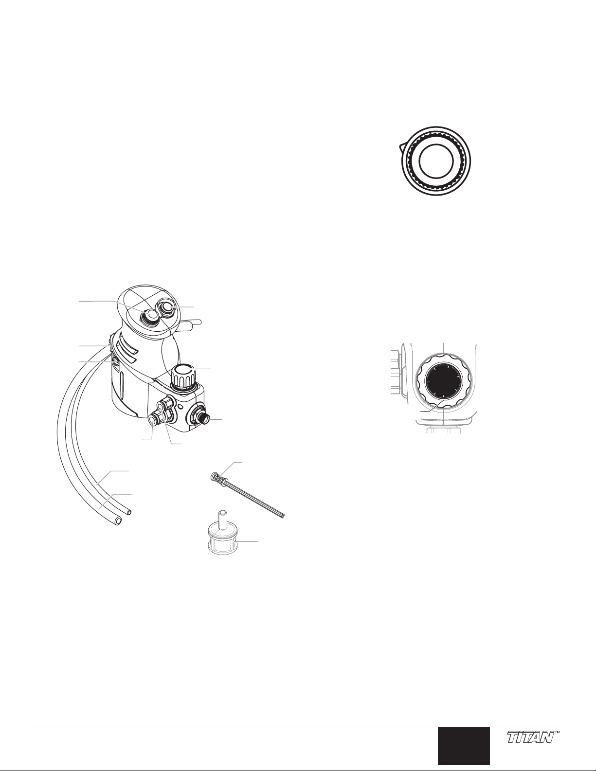
Specications
ON/OFF switch
*Material hose not shown
Speed
setting
knob
Pressure
setting knob
Siphon
filter
Return tube
fitting
Siphon tube
fitting
Fuse
Connector
Outlet
valve
Return tube
(smaller diameter)
Inlet valve
tool
Siphon tube
(larger diameter)
MEDIUM
LOW
HIGH
FLUSH
PRESSURE
PRIME
1
2
3
4
5
6
6:00
Max working ow rate .... 20 oz./min at 35 PSI
Max ow rate ushing
(Free ow) .....................40 oz./min
Maximum working
pressure......................... 35 PSI (2.4 MPa)
Power ............................PMDC brushed motor, 120 VAC, 60 Hz,
0.40 A
Weight ...........................3.3 lbs (1.5 kg)
Hose length ...................30 ft (9.1 m)
Introduction
The HVLP Transfer Pump is designed for use with CAPspray
spray systems. The Transfer Pump adds tremendous versatility
to an already complete system. This system improves user
productivity during larger spraying jobs by siphoning material
directly from a material container instead of spraying from a
1-quart cup.
Components of the HVLP Transfer Pump include a Transfer
Pump, material hose, siphon tube and a return tube.
This unit is to be used in conjunction with Titan CAPSpray
series turbines, sold separately (models CS75, CS95, CS105 or
CS115).
Transfer Pump Controls
Speed settings
The speed setting is used to adjust the volume of material
available to the spray gun. It is best to use the lowest speed
possible in order to maximize seal life. For most applications,
LOW speed will perform sufciently while putting the least
amount of wear of the seals.
• LOW - up to 14 uid ounces per minute
• MED - up to 17 uid ounces per minute
• HIGH - up to 20 uid ounces per minute
• FLUSH - 40 ounces per minute (to be used only during
cleanup)
Pressure settings
The pressure setting is used to determine the amount of force
used to deliver the material. The pressure settings range from
PRIME (no pressure) to 6 (max pressure).
The pressure is determined by the gure shown at the 6:00
position (when looking directly at the front of the pump) on the
pressure setting knob.
With this HVLP spray system, you can achieve the highest
quality professional nish possible with little preparation or setup
time. Please review all the information contained in this manual
before operating the system.
Bypass Design
The pump is a positive displacement pump and will run
continuously. It differs from a typical airless piston pump in that
during operation, material will continuously circulate into the
pump and out the return tube unless the gun is triggered.
© Titan Tool. All rights reserved. 3
English
Page 4
Setup
Air tube
Retaining nut
Pressure cap
Cup assembly
Pressure cap
Set screw
Air tube fitting
Connector
cover
Return tube
Collars
Siphon tube
Use the following procedures to set up your Transfer Pump.
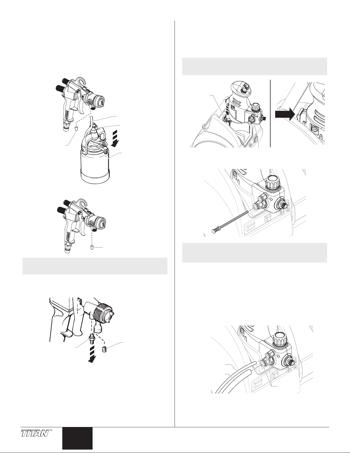
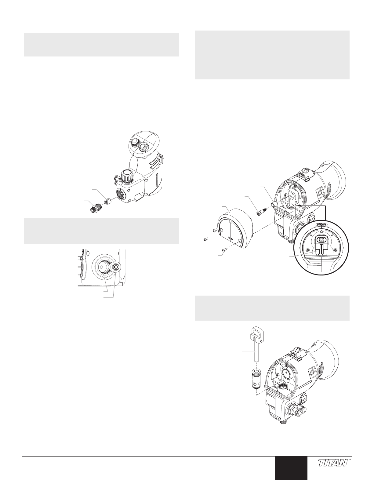
Converting the Gun to Pressure Feed
Before using the HVLP Transfer Pump, it is necessary to convert
your spray gun from a cup gun to a pressure fed gun.
1. Loosen the retaining nut using a wrench and remove the
one quart cup assembly.
2. Pull the air tube off of the air tube tting on the spray gun.
Mounting the Transfer Pump
1. Make sure both the turbine and Transfer Pump are turned
OFF (0).
2. Locate the small connector cover on the top of the turbine.
Open the cover and slide the Transfer Pump into the
turbine cup holder.
NOTE: The cover should click over the locking tabs and
securely hold the pump in place.
3. Insert the inlet valve pusher tool into the inlet valve. This
will free the poppet valve from the valve seat, ensuring the
pump will prime properly.
3. Cap off the air tube tting with the air tube cap.
Optional: Follow steps 4 and 5 if you have a Maxum II
gun only.
4. Remove the air tube tting using a 1/4” wrench.
5. Thread the set screw into the air tube tting location and
tighten into place.
NOTE: To prevent the poppet valve and seat from
sticking, make sure to follow all Cleanup
instructions after using the pump.
4. Dip the ends of the siphon and return tubes into solvent.
This will make them easier to secure to the Transfer
Pump.
5. Insert the suction and return tubes:
a. Press inward on the blue collar and rmly insert the
siphon tube (the larger tube) into the inlet valve tting.
b. Press inward on the blue collar and rmly insert the
return tube (the smaller tube) into the return tube tting.
c. Strongly pull on the tubes to make sure the connections
are secure.
4 © Titan Tool. All rights reserved.
English
Page 5
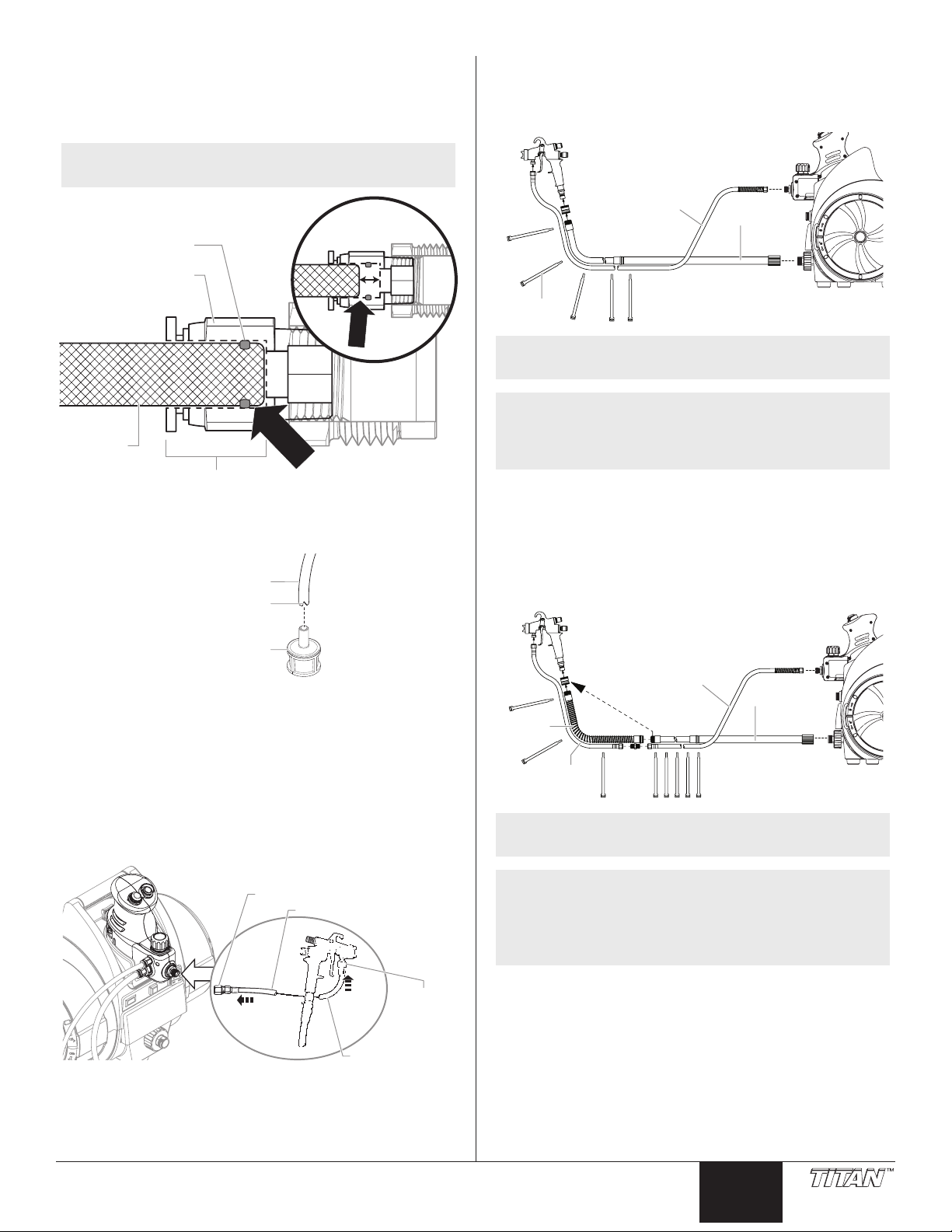
IMPORTANT: Make sure the siphon tube is firmly inserted
~3/4” (19 mm)
Siphon
tube
Inlet fitting
O-ring
Incorrect
Correct
Siphon tube
Notch
Siphon filter
Outlet valve
Fluid hose
Fluid hose
Spray gun
Inlet
Air hose
Fluid
hose
Straps
Air hose
Fluid hose
Fluid whip
hose
Air whip
hose
Straps
Move coupling
into the inlet fitting, past the O-ring as shown below. If the
tube is not fully inserted, a seal will not be achieved and the
pump will not prime. DO NOT insert the notched end of the
suction tube into the inlet fitting.
Hose Congurations
Spraying without whip hoses
Follow the conguration below if you want to spray without the
uid and air whip accessories.
NOTE: The siphon tube should go into the inlet
approximately 3/4” in order to be fully inserted.
6. If desired, attach the siphon lter at the notched end of the
siphon tube (the larger tube). The lter will prevent any
debris in the spray material from getting into the pump.
NOTE: When strapping the hoses together, start at the
spray gun and work your way back.
NOTE: 30 ft uid hose - included with Transfer Pump
30 ft air hose - included with turbine (25 ft air
hose included with CS75)
Hose straps - included with Transfer Pump
Spraying with whip hoses
Follow the conguration below if:
1. You already have the air whip hose and you purchased a
uid whip hose kit.
2. You have purchased both the uid whip hose kit and the
air hose whip kit.
7. Make sure the electrical service is 120V, 15 amp
8. Plug the turbine power cord into a properly grounded
Connecting the Material Hose
1. Thread the end of the uid hose onto the Transfer Pump
2. Thread the other end of the material hose onto the spray
© Titan Tool. All rights reserved. 5
minimum.
outlet at least 25’ from the spray area.
uid outlet and tighten with a wrench.
gun inlet and tighten with a wrench.
NOTE: When strapping the hoses together, start at the
spray gun and work your way back.
NOTE: 30 ft uid hose - included with Transfer Pump
30 ft air hose - included with turbine
5 ft air whip hose - included with the CS105 and
CS115
5 ft uid whip hose - sold separately.
English
Page 6
Operation
Return
tube
Mineral
spirits
Waste
container
Siphon
tube
Material Thinning
IMPORTANT: Thin the spray material properly for use in
the pump and spray gun. Refer to the spray gun manual for
thinning recommendations.
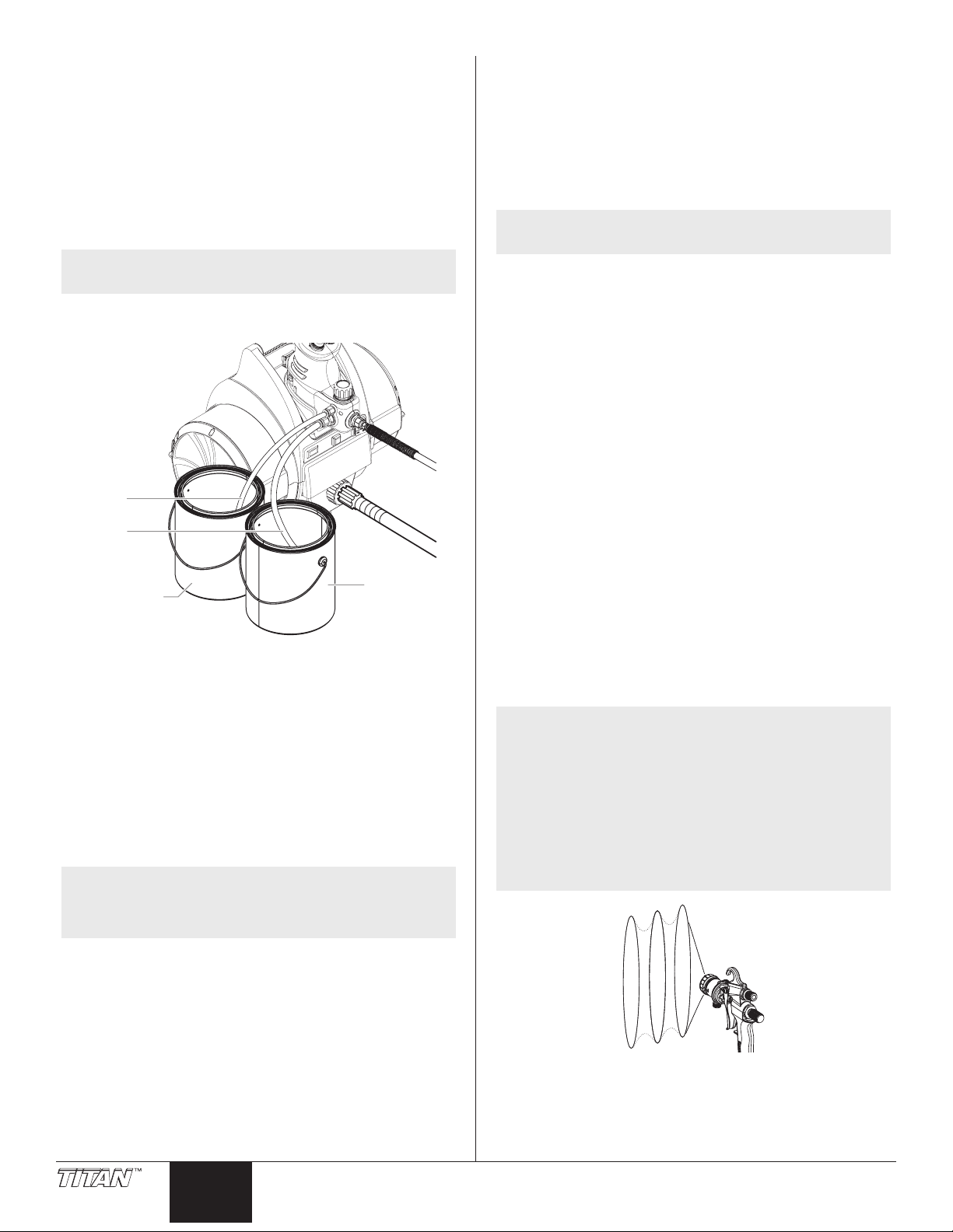
Preparing a New Pump
If this pump is new, it is shipped with test uid in the uid section
to prevent corrosion during shipment and storage. This uid
must be cleaned out of the system thoroughly with mineral spirits
before spraying any material.
NOTE: The turbine should be turned OFF (0) during
these steps.
1. Place the siphon tube into a container of mineral spirits.
2. Place the return tube into a metal waste container.
3. Set the pressure to PRIME by turning the pressure setting
knob fully counterclockwise.
4. Set the speed setting knob to LOW.
5. Turn the Transfer Pump ON/OFF switch to ON (the switch
should light up green).
6. Allow the pump to run for 15-30 seconds to ush the test
uid out through the bypass/return hose and into the
waste container.
7. Turn the Transfer Pump ON/OFF switch to OFF (0).
Preparing to Paint
Before spraying, it is important to make sure that the uid in the
system is compatible with the material that is going to be sprayed.
NOTE: Incompatible uids and paint may cause the
valves to become stuck closed, which would
require disassembly and cleaning of the pump’s
uid section.
7. Turn the Transfer Pump ON/OFF switch to OFF (0).
8. Turn up the pressure adjust knob to setting 2-3.
9. Turn the Transfer Pump ON/OFF switch to ON.
10. Trigger the spray gun into a metal waste container until
the old solvent is gone and fresh solvent is coming out of
the gun.
Painting
NOTE: The turbine should be turned OFF (0) during
these steps below until directed to do so.
1. Place the siphon tube into a container of the material you
plan to spray.
2. Place the return tube into a metal waste container.
3. Set the pressure to PRIME by turning the pressure setting
knob fully counterclockwise.
4. Set the speed selector knob to LOW.
5. Turn on the pump by pressing the ON/OFF switch to the
ON position.
6. Allow the pump to run until material is coming through the
return tube into the metal waste container.
7. Turn off the pump by pressing the ON/OFF switch to the
OFF position.
8. Remove the return tube from the waste container and
place it in the container of spray material.
9. Turn up the pressure adjust knob to 3-4.
10. Turn the Transfer Pump ON/OFF switch to ON.
11. Trigger the gun into the metal waste container until all air
and solvent is ushed from the spray hose and paint is
owing freely from the gun.
12. Set the speed setting knob to:
a. LOW for #2 and #3 prosets
b. LOW-MED for #4 and #5 prosets
c. MED - HIGH for #6 and #7 prosets
13. Adjust the pressure by turning the pressure control knob
slowly and watch for a gently arcing stream to exit the gun
nozzle when triggered.
NOTE: Generally, for thin materials such as
polyurethanes, lacquers, and stains, set pressure
between numbers 1 to 2. For thicker materials
such as latex paint, set pressure to 2 or higher.
NOTE: For some very thin spray materials, a pulsating
spray pattern may be encountered when using
lower pressures (see picture below). To correct
this, increase pump pressure to 4 or 5, then
decrease the needle travel on the spray gun to
achieve the desired ow rate. This will increase
back pressure in the material hose and smooth
out the spray pattern.
1. Place the siphon tube into a container of the appropriate
solvent. Examples of the appropriate solvent are water
for latex-based materials or mineral spirits for oil-based
materials.
2. Place the return tube into a metal waste container.
3. Set the pressure to PRIME by turning the pressure setting
knob fully counterclockwise.
4. Set the speed selector knob to FLUSH.
5. Turn on the pump by pressing the ON/OFF switch to the
ON position.
6. Allow the pump to run for 15–30 seconds to ush the old
solvent out through the return tube and into the metal
waste container.
6 © Titan Tool. All rights reserved.
English
14. Turn on turbine by moving the turbine ON/OFF switch to
the ON position.
15. Practice spraying on a piece of scrap wood or cardboard
until you are satised with the pressure, spray pattern, and
spray shape. The spray pattern adjustments and spray
shape selections are described in your gun manual.
Page 7
Drip tray
Drip holes
Outlet valve
cage
Outlet valve
fitting
Inlet
fitting
Inlet
valve
O-ring
Poppet
Window
Guide
Tab
Cleanup
NOTE: Thorough cleaning and maintenance of your
• Always ush spray gun preferably outside and at least one
• If collecting ushed solvents in a one gallon metal
• Area must be free of ammable vapors.
• Follow all cleanup instructions.
IMPORTANT: The pump, hose, and gun should be cleaned
thoroughly after daily use. Failure to do so permits material
to build up, seriously affecting the performance of the unit.
1. Turn off the turbine and pump.
2. Place the siphon tube into a container of the appropriate
3. Place the return tube into a metal waste container.
4. Set the pressure to PRIME by turning the pressure setting
5. Set the speed setting knob to FLUSH.
6. Turn on the Transfer Pump by pressing the ON/OFF
7. Allow the solvent to circulate through the pump and ush
8. Turn off the Transfer Pump by pressing the ON/OFF
9. Turn up the pressure adjust knob to setting 2-3.
10. Turn on the Transfer Pump by pressing the ON/OFF
11. Trigger the gun into the metal waste container until the
12. Continue to trigger the spray gun into the waste container
13. Turn off the Transfer Pump by pressing the ON/OFF
14. Set the pressure to PRIME by turning the pressure setting
NOTE: For long-term or cold weather storage, pump
15. Disconnect siphon and return tubes by pressing inward on
16. Disconnect the material hose from the front of the Transfer
IMPORTANT: After each use, inspect the drip tray and heel
cover for leakage. If drips are present, service seal as soon
as possible (see Replacing the Seal and PIston, page 8).
© Titan Tool. All rights reserved. 7
Transfer Pump is the best way to ensure
prolonged useful life of the unit. Follow all
Cleanup steps, including Cleaning the Inlet and
Outlet Valves.
Special cleanup instructions for use with
flammable solvents:
hose length from spray pump.
container, place it into an empty ve gallon container, then
ush solvents.
solvent. Examples of the appropriate solvent are water for
latex materials or mineral spirits for oil-based materials.
knob fully counterclockwise.
switch to the ON position.
the paint out of the return hose into the metal waste
container until uid is clear.
switch to the OFF position.
switch to the ON position.
paint is ushed out of the hose and solvent is coming out
of the gun.
until the solvent coming out of the gun is clean.
switch to the OFF position.
knob fully counterclockwise.
mineral sprits through the entire system.
the collar while pulling outward on the tube.
Pump with a wrench. It may be necessary to hold the
outlet tting on the pump with another wrench while
turning the swivel nut attached to the hose.
17. Remove the Transfer Pump from the turbine and tip to the
side and front to drain any excess solvent from the pump.
IMPORTANT: Flip up the connector cover to allow pump to
be lifted out of cupholder in turbine.
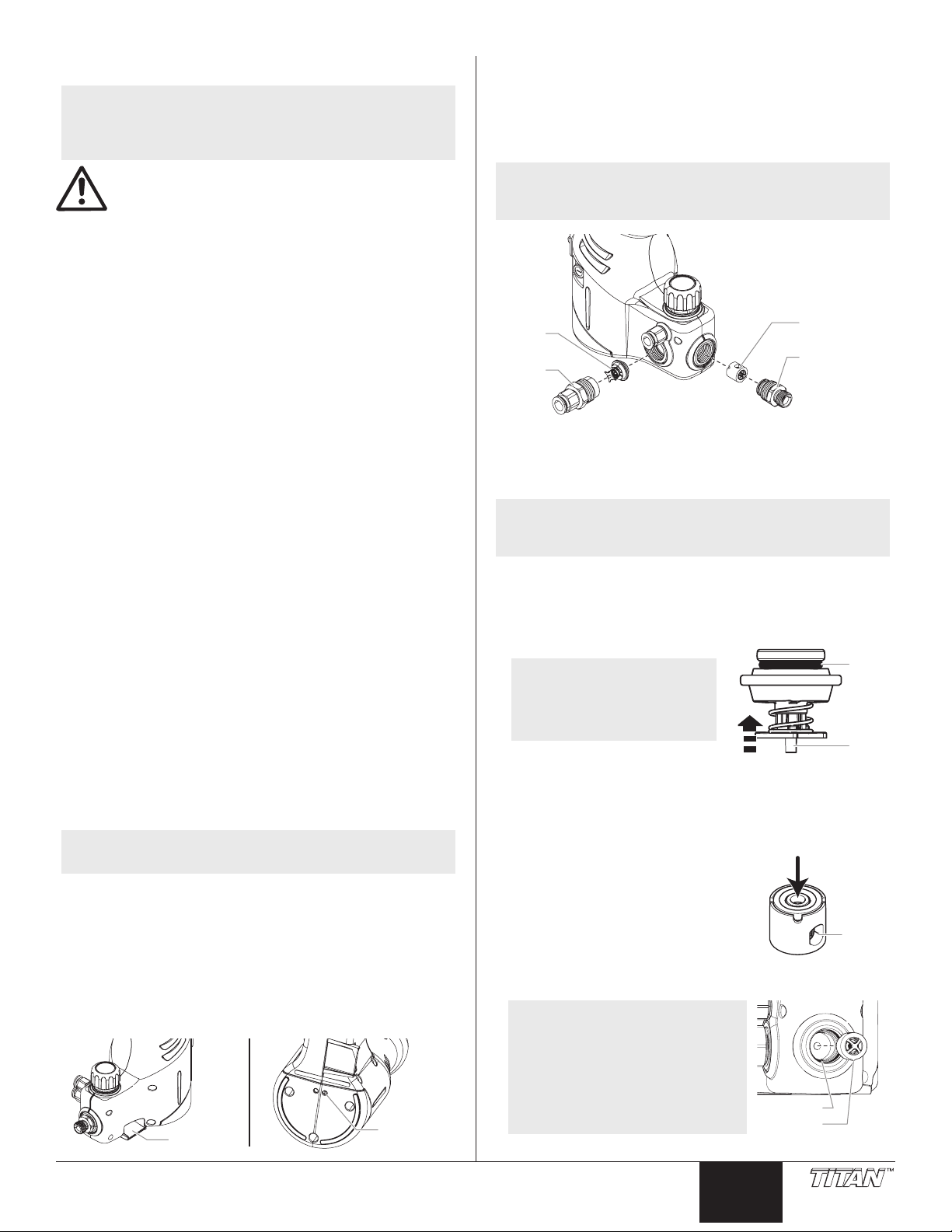
Cleaning the Inlet / Outlet Valves
NOTE: Cleaning the inlet and outlet valves should be
performed after every use to ensure continued
useful operation of the unit.
1. Remove the inlet valve:
a. Using an adjustable wrench, remove the inlet tting
(apply the wrench to the larger hex diameter).
b. Remove inlet valve assembly.
NOTE: To free the inlet valve assembly, gently rock the
inlet valve assembly back and forth to free it from
the pump housing.
2. Clean the inlet valve:
a. Clean the poppet and O-ring area of the inlet valve and
the inside of the inlet tting using a soft bristled brush
and the appropriate cleaning solution. The inlet valve
should be free from all spraying residue.
NOTE: Push up on the
poppet on the inlet
valve to expose the
O-ring in order to
clean it.
3. Remove the outlet valve:
a. Using an adjustable wrench, remove the outlet tting.
b. Remove the outlet valve cage assembly.
4. Clean the outlet valve:
a. Clean the outlet valve cage using a soft-bristled brush
and the appropriate cleaning solution.
b. Using a pen, gently push
through the center opening to
activate the poppet and make
sure it moves freely (it should
move approximately 1/32”).
This movement can be seen
through the side window of the
cage.
5. Replace outlet valve cage assembly.
NOTE: When replacing the outlet
valve cage, make sure
to line up the slot in the
cage with the guide in
the outlet valve housing.
The guide is located at
the 6:00 o’clock position
inside the housing.
6. Replace the outlet valve tting - torque to 180-200 in-lbs.
English
Page 8
7. Replace inlet valve assembly.
Shoulder
screw
Oil
Oil
Heel cover
Screw
Inlet valve
Inlet fitting
8. Assemble inlet tting - torque to 160-180 in-lbs.
9. Add a few drops of piston lube inside the inlet valve
tting, the return tube tting and the outlet valve. This will
improve priming the next time the pump is used.
10. Store in a clean, dry area.
11. Wipe down tubes, hose, and gun.
12. Store pump in an upright position.
IMPORTANT: Do not store inlet fitting and bypass/return
fitting immersed in hot solvents such as Acetone, Lacquer
Thinner or MEK. If you wish to soak these fittings, immerse
in mineral spirits.
NOTE: To remove material build-up and prolong inlet/
outlet valve life, soak the valves in lacquer
thinner overnight periodically. This will loosen
up any accumulated material between the O-ring
and valve seat.
Maintenance
Follow all other warnings to reduce the risk of an
injection injury, injury from moving parts or electric
shock. Always disconnect the pump before
servicing!
After every use
• Oil inlet valve, outlet valve, and quick connect ttings with
a few drops of Titan Piston Lube.
Monthly
• Remove heel cover. Lubricate crank components with
a few drops of Titan Piston Lube. Insert an 9/32 allen
wrench into the shoulder screw and rotate the eccentric to
draw oil into cracks. Do not use grease.
General Repair and Service Notes
1. Before repairing any part of the Transfer Pump, read the
instructions carefully, including all warnings.
IMPORTANT: Never pull on a wire to disconnect it. Pulling
on a wire could loosen the connector from the wire.
2. Test your repair before regular operation of the sprayer
to be sure that the problem is corrected. If the sprayer
does not operate properly, review the repair procedure to
determine if everything was done correctly. Refer to the
Troubleshooting section to help identify other possible
problems.
3. Make certain that the service area is well ventilated in
case solvents are used during cleaning. Always wear
protective eyewear while servicing. Additional protective
equipment may be required depending on the type of
cleaning solvent. Always contact the supplier of solvents
for recommendations.
4. If you have any further questions concerning your TITAN
airless pump, call TITAN:
Technical Service (U.S.) .......................1-800-526-5362
Fax ................................................1-800-528-4826
Technical Service (Canada) .................. 1-800-565-8665
Fax .................................................1-800-856-8496
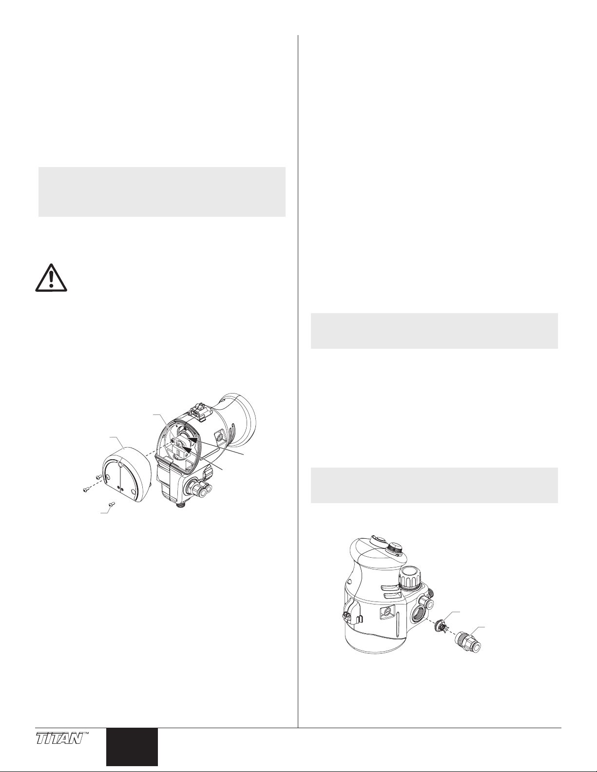
Service
Replacing the Inlet Valve
NOTE: The inlet valve in this pump will need to be
serviced approximately every 10-20 hours of run
time depending on media type and speed setting.
1. Perform CLEANUP procedure.
2. Adjust pressure to PRIME position.
3. Remove siphon and return tubes.
4. Remove material hose
5. Remove pump from turbine, ensuring power is removed.
6. Tip pump on its side to drain excess solvent. The unit
should be tipped on the side that contains the ttings for
the siphon/return tubes.
7. Remove inlet tting.
8. Remove inlet valve assembly.
NOTE: To free the inlet valve assembly, gently rock the
9. Replace with new inlet valve assembly.
10. Assemble inlet tting - torque to 160-180 in-lbs.
8 © Titan Tool. All rights reserved.
English
inlet valve assembly back and forth to free it from
the pump housing.
Page 9
Replacing the Outlet Valve
Outlet valve cage
Outlet valve fitting
Guide
Tab
Shoulder
screw
Bushing
Heel cover
Wedge
wrench
here
Screw
Piston / yoke
assembly
Bushing /
seal assembly
Replacing the Seal and Piston
NOTE: The outlet valve in this pump will need to be
serviced approximately every 10-20 hours of run
time depending on media type and speed setting.
1. Perform CLEANUP procedure.
2. Adjust pressure to PRIME position.
3. Remove material hose.
4. Remove pump from turbine, ensuring power is removed.
5. Tip pump on its side to drain excess solvent. The unit
should be tipped on the side that contains the ttings for
the siphon/return tubes.
6. Remove outlet tting.
7. Remove and replace outlet valve cage assembly.
8. Assemble outlet tting - torque to 180-200 in-lbs.
NOTE: The seal in this pump will need to be serviced
approximately every 30-60 hours of run time
depending on media type and speed setting.
The seal and piston should be replaced as a set.
Replace the seal and piston at the rst sign of
leakage from the drip tray or from the underside
of the pump supported by the cup holder of the
turbine.
1. Perform CLEANUP sequence on the pump and hose.
2. Adjust pressure to PRIME position thus relieving pressure
from the system.
3. Remove inlet and outlet tubes.
4. Remove material hose.
5. Remove pump from turbine thus ensuring power is
removed.
6. Tip pump on its side to drain excess solvent.
7. Remove heel cover using a #2 Phillips screwdriver.
8. Use a crescent wrench to jam the eccentric. Remove
shoulder bolt and bushing with 9/32 allen wrench.
NOTE: When replacing the outlet valve cage, make sure
to line up the slot in the cage with the guide in
the outlet valve housing. The guide is located at
the 6:00 position inside the housing.
9. Remove piston and yoke assembly from bushing.
10. Using a crescent wrench, unthread bushing from housing.
NOTE: There is approximately three (3) threads of
engagement on the bushing. You will need to
use a pliers to fully remove the bushing/seal
assembly from the housing.
© Titan Tool. All rights reserved. 9
11. Using a small brush and appropriate solvent, clean out
any dried material in the bushing/seal cavity and also the
drip dray and drip hole in the housing.
English
Page 10
IMPORTANT: Do not allow solvent to drain into the motor
Bushing
Seal
assembly
Set screw
Pressure
knob
Locking
nut
Stem
Spring
Diaphragm
assembly
Seat
PRESSURE
PRIME
1
2
3
4
5
6
6:00
enclosure of the pump.
12. Wipe out excess moisture from cavity and apply a lm of
piston lube or light grease to the inside of the cavity.
13. Replace the seal in the bushing:
a. Place bushing in vise (do not
over clamp - may egg-shape
the hole)
b. Using a small at blade
screwdriver, carefully pry the
seal from the bushing.
c. Using a brush and solvent,
clean and inspect the
bushing.
d. Measure the bushing. If the
bushing inner diameter at
either end is more than 0.441 inches, then the bushing
should be replaced. A new bushing will prolong seal
life.
e. Placing the new seal at on a
stable surface, snap the bushing
over the seal.
14. Fill the bushing cavity with light
grease and temporarily slide the
piston through to force out any
excess. Wipe off grease from tip of
piston and remove.
15. Slide the bushing into the bushing/
seal cavity in the housing up to the
start of the threads.
16. Engage the threads while rotating the bushing/seal
assembly.
17. Screw the assembly in until the hex bottoms against the
spot face in the housing (35-45 in-lbs).
18. Placing the yoke/piston assembly in a vise, remove and
replace the old piston with the new piston in the seal/
piston kit (torque the socket head screw to 60-70 in-lbs).
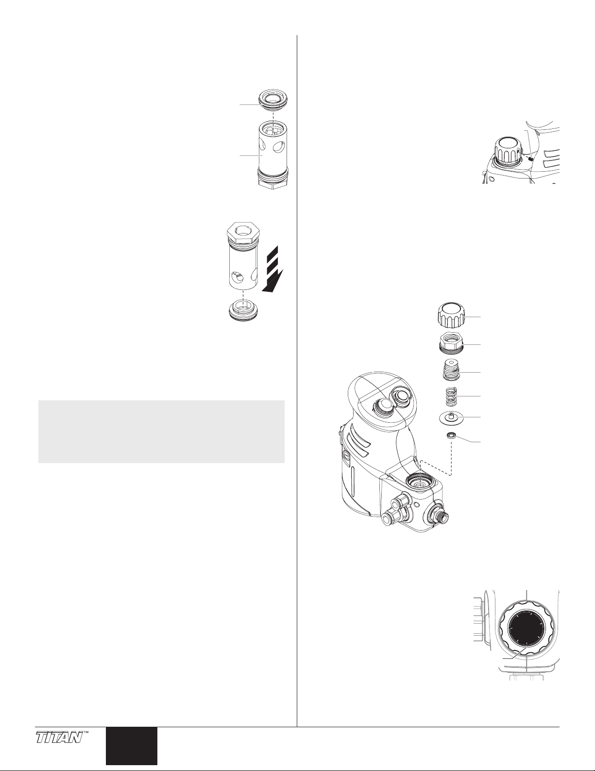
Replacing the Pressure Setting Valve
1. Perform CLEANUP procedure.
2. Adjust pressure to PRIME position.
3. Remove material hose.
4. Remove pump from turbine, ensuring power is removed.
5. Tip pump on its side to drain excess solvent. The unit
should be tipped on the side that contains the ttings for
the siphon/return tubes.
6. Remove pressure adjustment knob
set screw using a 1/8 allen wrench.
Remove the knob.
7. Remove diaphragm locking nut
using an adjustable wrench.
8. Remove stem from locking
nut, taking care not to lose the
compression spring.
9. Remove the diaphragm assembly from the pump housing.
10. Carefully pry the worn seat from the pump housing.
11. Clean the seat bore in the pump housing.
12. Apply a thin lm of adhesive into the seat recess.
13. Press new seat into seat bore and wipe away excess
adhesive.
14. Assemble diaphragm assembly into the pump, taking care
to ensure the edge of the diaphragm disk are pushed past
the threads and within the thread relief.
NOTE: If the yoke is worn excessively, it should be
replaced at this time along with the driver
bushing and driver screw. If the yoke slot
measures greater than .510 inches wide, then
the yoke, shoulder bolt and eccentric bushing
should be replaced as a set.
19. Slide the new piston and yoke assembly into the bushing/
seal assembly oriented as shown.
20. Align the yoke slot with the eccentric threaded hole.
21. Thread the shoulder screw and bushing into the eccentric
while jamming the yoke again with the wrench. Torque
shoulder screw to 50-60 in-lbs.
22. Replace the heel cover and screws - Torque screws to 6-8
in-lbs.
15. Apply a generous coat of grease the stem threads
16. Assemble spring, stem and locking nut.
17. Torque locking nut to 100-120 in-lbs
18. Rotate stem counter-clockwise until it is backed out as far
as possible. This is the PRIME position.
19. Without turning the stem,
assemble the pressure
adjustment knob and lock
down so the PRIME notation is
oriented as shown.
20. Apply Loctite 243 to the threads
of the set screw. Tighten the
set screw on the pressure
adjustment knob. Torque to 6-8
in-lbs.
10 © Titan Tool. All rights reserved.
English
Page 11
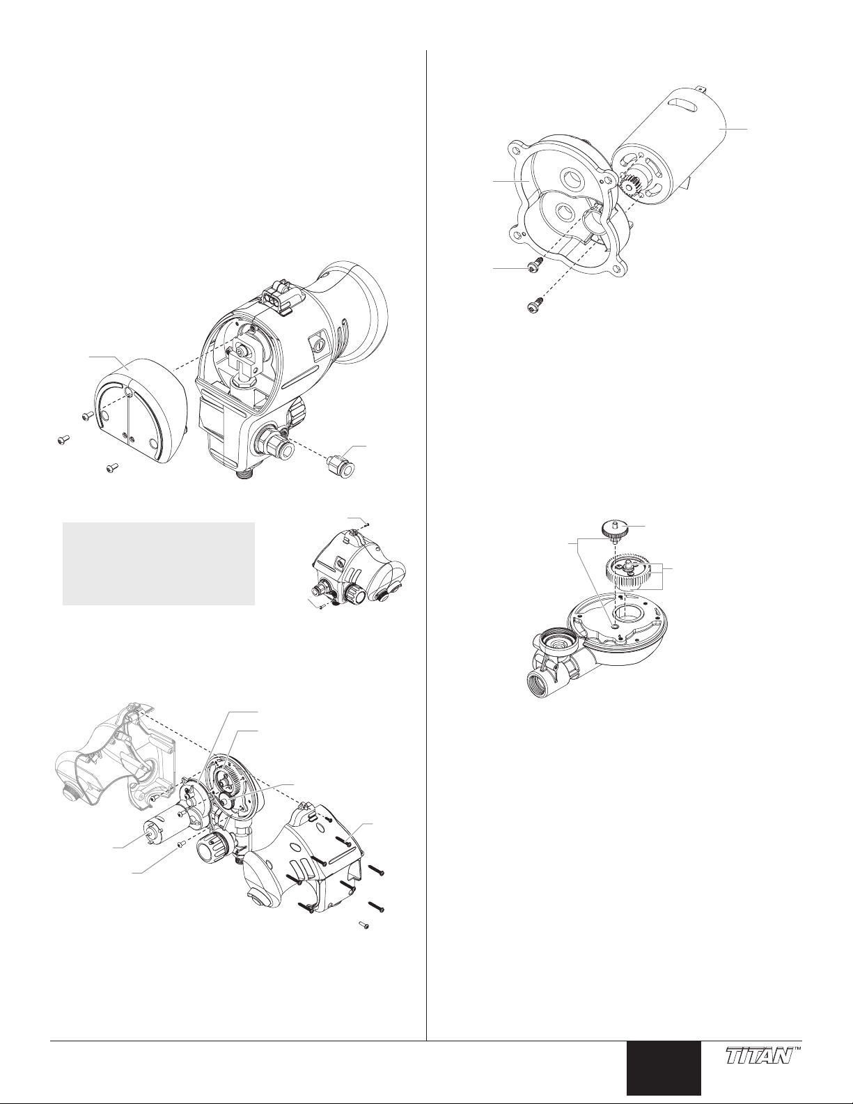
Replacing the Motor
Return
tube
fitting
Heel
cover
Screw
Screw
Case
screw
Gear case
screw
Motor
Gear case
Eccentric
Gear
Motor
screw
Gear
case
Motor
Piston Lube™
Grease this gear
face only
Piston Lube™
1. Perform CLEANUP procedure.
2. Adjust pressure to PRIME position.
3. Remove siphon and return tubes.
4. Remove material hose.
5. Remove pump from turbine, ensuring power is removed.
6. Tip pump on its side to drain excess solvent. The unit
should be tipped on the side that contains the ttings for
the siphon/return tubes.
7. Remove the return tube tting.
8. Using a thin blade, slit top label down the center to allow
the case halves to separate.
9. Remove heel cover.
10. Remove the ten (10) case screws.
14. Remove two (2) motor screws from gear case. Remove
the motor.
15. Inspect the gears and eccentric. Apply a lm of piston
lube.
IMPORTANT: Lubricate as shown below. Apply grease only
where indicated. Additional grease can cause excessive
drag on the motor and cause overheating.
16. Assemble in reverse order using the following torques:
a. Motor Screws (2) = 4-6 in-lbs
b. Gear Case (4) = 12-15 in-lbs
c. #6 Case screws (9) = 5-6 in-lbs
d. #4 Case screw (1) = 1-2 in-lbs
e. Heel cover screws (3) = 6-8 in-lbs
f. Return tube tting (1) = 15-20 in-lbs
NOTE: Do not forget the
11. Gently pull apart case halves away from pump housing
12. Remove the two (2) connectors from motor terminals.
13. Remove the four (4) gear case screws from pump
single screw on the
other side of the
pump or the the small
#4 screw near the
electrical connection.
assembly.
housing. Remove the gear case.
© Titan Tool. All rights reserved. 11
English
Page 12

Troubleshooting
Problem
A. Pump will not run and green
light is out
B. Pump will not run and green
light is on
C. Pump runs but does not
prime.
D. Pump primes and is returning
to the material container
through the bypass/return
tube, but nothing is coming
out of the gun.
E. Spray pattern is too light.
F. Spray pattern is too heavy
G. Pulsating spray pattern while
using thin materials.
Cause
1. Pump is not fully locked into turbine.
2. Turbine is not plugged in.
3. Fuse is blown in the pump.
4. Faulty or loose wiring.
1. Faulty motor.
2. Faulty board.
1. Inlet valve is stuck.
2. Siphon tube is not fully inserted into the
inlet tting.
3. Siphon tube not fully immersed in the
spray material.
4. Pressure setting knob not set to PRIME.
5. Inlet tting is not tightened properly.
6. Quick-connect inlet tting is damaged or
dirty.
7. Inlet valve is worn or contains material
buildup.
8. Siphon tube or lter is clogged.
9. Faulty outlet valve.
1. Pressure too low.
2. Spray material is too thick.
3. Pressure setting valve poppet and set are
worn.
1. Gun not adjusted properly, or too small of
a projector set is being used.
2. Pressure too low.
3. Spray material is too thick.
1. Pressure too high.
2. Gun not adjusted properly.
1. Pressure too low, too much needle travel
on the spray gun.
Solution
1. Ensure there is not something binding under the
pump preventing it from fully seating and ensure
the connector cover has engaged (clicked over) the
locking tabs on the pump.
2. Check turbine lighted cord, it should be lit. Plug in.
3. Remove heel cover and lubricate eccentric (see
Service, Replacing the Seal and Piston section).
Replace the fuse. If it blows repeatedly, the seal
must be serviced immediately. Use only fuse type
specied in the Parts List. Using other types of fuse
may cause damage to the pump.
4. Take your Transfer Pump to an authorized service
center.
1. Replace the motor (see Service, Replacing the
Motor section).
2. Replace the board.
1. Remove siphon tube and depress inlet valve with
inlet valve tool (or some other long, slender tool).
2. Fully insert and secure the siphon tube into the inlet
connection.
3. Immerse the siphon tube into the spray material.
4. Turn the pressure setting knob fully
counterclockwise.
5. Tighten the inlet tting to 160-180 in-lbs.
6. Clean or replace.
7. Replace the inlet valve (see Service, Replacing the
Inlet Valve section).
8. Clean the siphon tube and lter.
9. Replace the outlet valve (see Service, Replacing
the Outlet Valve section).
1. Turn the pressure setting knob clockwise to increase.
2. See recommended thinning section in spray gun
manual.
3. Replace (see Service, Replacing the Pressure
Setting Valve section).
1. See spray gun manual for gun adjustment
procedures and projector set information.
2. Turn the pressure setting knob clockwise to increase.
3. See recommended thinning section in spray gun
manual.
1. Turn the pressure setting knob counterclockwise to
decrease.
2. See spray gun manual for gun adjustment
procedures.
1. Increase pump pressure to 4 or 5, and decrease the
needle travel on the spray gun.
H. Material is leaking on or from
the drip tray or cupholder.
12 © Titan Tool. All rights reserved.
English
1. Seal and piston are worn.
1. Replace the piston and seal (see Service,
Replacing the Seal and Piston section).
Page 13

Notes
© Titan Tool. All rights reserved. 13
English
Page 14
Consignes de sécurite important · Lire toutes ces consignes avant
d’utiliser l’appareil. GARDER CES CONSIGNES.
Indique une situation à risque, laquelle, si elle n’est pas
évitée, peut entraîner des blessures graves, voire la mort.
Pour réduire les risques d’incendie ou d’explosion, de
choc électrique et de blessure, vous devez lire et
comprendre les directives figurant dans ce manuel.
Familiarisez-vous avec les commandes et l’utilisation
adéquate de l’équipement.
DANGER: RISQUES D’EXPLOSION PAR
Peuvent être à l’origine de corporels sérieux ou dommages
matériels.
PRÉVENTION :
• Ne pas utiliser de matériaux contenant des agents de
• Ne pas utiliser des solvants à base d’hydrocarbure halogéné
• Communiquer avec votre fournisseur de revêtement pour
DANGER : GÉNÉRAUX
Risques de dommages matériels et de blessures graves.
PRÉVENTION :
• Lire toutes les directives et mises en garde avant de faire
• Se conformer à tous les codes locaux, provinciaux et nationaux
• Les normes de sécurité adoptées par le gouvernement américain
• Cet équipement est conçu pour fonctionner avec les pièces
• On doit s’assurer que les tuyaux soient exempts de coupures,
• Ne jamais pulvériser lorsqu’il vente.
• Porter des vêtements pour protéger la peau et les cheveux contre
• On ne doit jamais orienter le pistolet vers une partie du corps.
DANGER : D’EXPLOSION OU D’INCENDIE
Les émanations de solvants et de peintures peuvent
exploser ou s’enammer, entraînant des dommages
matériels ou des blessures graves.
PREVENTION :
• On doit assurer la ventilation et l’introduction d’air
• Le turbine contient des pièces qui peuvent émettre
• Il faut éviter les sources de combustion comme l’électricité
• S’entourer de toutes les précautions possibles lorsqu’on utilise
INCOMPATIBILITÉ DES MATÉRIAUX
blanchiment ou du chlore.
tels que l’agent anticryptogamique, le chlorure de méthylène et
le trichloro-éthane-1,1,1. Ces produits ne sont pas compatibles
avec l’aluminium.
connaître la compatibilité du matériau avec l’aluminium.
fonctionner l’équipement, quel qu’il soit.
qui régissent la ventilation, la prévention des incendies et le
fonctionnement des dispositifs.
l’ont été en vertu de sa Occupational Safety and Health Act
(OSHA); ces normes, particulièrement les parties 1910 des
normes générales et 1926 des normes de construction, devraient
toujours être consultées.
autorisées seulement. Si on l’utilise avec des pièces non
conformes aux spécications et exigences en matière de sécurité
du fabricant, on devra accepter les responsabilités et risques
inhérents.
de fuites, d’abrasions ou de renements et que les raccords ne
soient ni endommagés ni mal assujettis avant chaque usage.
Le cas échéant, il faut remplacer le tuyau sur le champ, en ne
tentant jamais de le réparer.
tout contact avec la peinture.
neuf dans la zone de pulvérisation an d’éviter les
accumulations de vapeurs inammables.
des étincelles. Placer la turbine le plus loin possible de la zone
de pulvérisation.
statique, les ammes nues, les veilleuses de bec de gaz, les
objets chauds, les cigarettes et les étincelles provoquées
par la connexion/déconnexion de cordon d’alimentation et la
commutation d’interrupteurs d’éclairage.
des produits ayant un point d’éclair inférieur à 21 °C (70 °F). Le
point d’éclair d’un uide est la température à laquelle les vapeurs
émanant du uide peuvent s’enammer au contact d’une amme
ou d’une étincelle.
• On doit avoir à portée de la main de l’équipement d’extinction en
bon état de marche.
• Le cordon d’alimentation doit être raccordé à un circuit mis à la
terre.
• S’assurer de suivre les directives en matière de sécurité et de
lire les mises en garde du fabricant des solvants et des produits
utilisés.
DANGER: VAPEURS NOCIVES
La peinture, les solvants, les insecticides et autres matériaux peuvent
être nocifs lorsqu’ils sont inhalés ou en contact avec le corps. Les
vapeurs peuvent causer une nausée importante, des évanouissements
ou un empoisonnement.
PRÉVENTION :
• Utiliser un respirateur ou un masque chaque fois
qu’il y a des risques d’inhalation de vapeurs. Lire
attentivement toutes les instructions se rapportant
au masque pour vérier que celui-ci vous assure
une protection sufsante contre les vapeurs
toxiques.
• Porter des lunettes de protection.
• Porter des vêtements de protection, conformément aux directives
du fabricant de revêtement.
DANGER : RISQUE DE DÉCHARGE ÉLECTRIQUE
Risque de blessures graves.
PRÉVENTION :
• N’immergez jamais de pièce électrique dans l’eau ou tout autre
liquide. Essuyez l’extérieur de la pompe avec un linge humide
pour la nettoyer. Assurez-vous toujours que la pompe est
débranchée de la turbine avant de la démonter pour la nettoyer
ou l’entretenir.
Entretien et Réparations
Si le système requiert de l’entretien ou des réparations pendant la période
de la garantie, on doit le retourner, accompagné d’une preuve d’achat, au
distributeur chez qui on l’a acheté. Il sera alors, selon le choix du fabricant,
réparé ou remplacé. Dans le cadre de son engagement perpétuel
envers l’amélioration de la qualité, nous réservons le droit de modier les
composants ou la conception de ses produits si elle le juge nécessaire.
IMPORTANT : Ne jamais faire fonctionner l’appareil pendant
plus de dix secondes sans liquide. Un tel fonctionnement à sec
endommagerait inutilement le joint d’étanchéité.
Table des matières
Sécurité ......................................................................................... 14
Spécications ............................................................................... 15
Introduction ................................................................................... 15
Commandes du Transfer Pump .............................................. 15
Préparation.................................................................................... 16
Conversion du pistolet pour l’alimentation à pression ............ 16
Assemblage du Transfer Pump .............................................. 16
Raccordement du tuyau à peinture ......................................... 17
Congurations du tuyau .......................................................... 17
Fonctionnement ............................................................................ 18
Dilution du produit ................................................................... 18
Préparation d’un nouveau pompe ........................................... 18
Préparation avant de peindre ................................................. 18
Peinture ......................................................................................... 18
Nettoyage ...................................................................................... 19
Nettoyage des soupapes d’admission/de sortie ..................... 20
Maintenance .................................................................................. 20
Généralités concernant la maintenance ................................. 21
Entretien ........................................................................................ 21
Remplacement de la soupape d’admission ............................ 21
Remplacement de la soupape de sortie ................................. 21
Remplacement du joint d’étanchéité et du piston ................... 22
Remplacement de la soupape de réglage de pression .......... 23
Remplacement du moteur....................................................... 24
Dépannage .................................................................................... 25
Liste de pièces ......................................................................... 38-40
Diagramme électrique ............................................................. 41
Garantie ......................................................................................... 42
14 © Titan Tool. Tous droits réservés.
Français
Page 15

Spécications
Interrupteur
*tuyau en tissu non montré
Bouton de
réglage de
vitesse
Bouton de
réglage de
pression
Filtre
d’aspiration
Raccord du
tube de retour
Raccord
de tube
d’aspiration
Fusible
Connecteur
Soupape
de sortie
Tube de retour
(petit diamètre)
Outil de
soupape
d’admission
Tube d’aspiration
(grand diamètre)
MEDIUM
LOW
HIGH
FLUSH
PRESSURE
PRIME
1
2
3
4
5
6
6:00
Vitesse
d’utilisation max. ............ 20 onces liquides/min. à 35 lb/po2
Débit maximum, rinçage
(écoulement libre) .......... 40 onces liquides/min.
Pression d’utilisation
maximale ....................... 35 lb/po2 (2,4 MPa)
Puissance ...................... moteur à balais courant continu à
aimants permanents, 120 VAC, 60 Hz,
0,40 amp
Poids.............................. 3,3 lb (1,5 kg)
Longueur du tuyau......... 30 pi (9,1 m)
Introduction
Le Transfer Pump à débit élevé et à basse pression est conçu
pour être utilisé avec les systèmes de pulvérisation CAPspray.
Le Transfer Pump améliore la polyvalence d’un système déjà
complet. Ce système accroît la productivité de l’utilisateur lors
de grosses tâches de pulvérisation en siphonnant le produit
directement dans un récipient de matière liquide au lieu de le
prélever dans un godet d’une pinte.
Les composantes du Transfer Pump à débit élevé et à basse
pression sont un Transfer Pump, un tuyau en tissu, un tube
d’aspiration et un tube de retour.
Ce dispositif doit être utilisé avec les turbines Titan de la série
CAPSpray, vendues séparément (modèles CS75, CS95, CS105
ou CS115).
Commandes du Transfer Pump
Réglages de vitesse
Le réglage de vitesse sert à ajuster le volume de produit
disponible dans le pistolet pulvérisateur. Il vaut mieux utiliser la
vitesse la plus basse possible pour maximiser la durée de vie
du joint d’étanchéité. Pour la plupart des applications, la vitesse
BAS sera sufsante et sera moins dommageable pour les joints
d’étanchéité.
• LOW (bas) – jusqu’à 14 onces liquides la minute
• MEDIUM (moyen) – jusqu’à 17 onces liquides la minute
• HIGH (élevé) – jusqu’à 20 onces liquides la minute
• FLUSH (rinçage) – 40 onces la minute (n’utiliser qu’au
nettoyage)
Réglages de pression
Le réglage de pression sert à déterminer le niveau de force
utilisé pour acheminer le produit. Le réglage de pression varie
entre PRIME (aucune pression) et 6 (pression maximale).
La pression est déterminée par l’image montrée à la position 6 h
(lorsqu’on regarde directement à l’avant de la pompe) du bouton
de réglage de pression.
Grâce à ce système de pulvérisation à débit élevé et à basse
pression, il est possible d’obtenir un ni professionnel de grande
qualité avec un minimum de préparation et d’installation. Veuillez
passer en revue toute l’information du présent manuel avant
d’utiliser le système.
Concept de dérivation
L’appareil est une pompe volumétrique à débit continu. Elle
diffère d’une pompe à piston sans air ordinaire en ce sens que,
en plein fonctionnement, le produit circulera de façon continue
dans la pompe et sortira du tube de retour, à moins qu’on appuie
sur la détente.
© Titan Tool. Tous droits réservés. 15
Français
Page 16

Préparation
Tube d'air
Écrou de retenue
Bouchon à
soupape de
pression
Ensemble godet
Bouchon à soupape
de pression
Raccord pour
tuyau à air
Vis de montage
Couvercle de
connecteur
Tube de retour
Tube d’aspiration
Bague
Suivez les procédures suivantes pour préparer votre Transfer
Pump HVLP à l’emploi.
Conversion du pistolet pour l’alimentation à
pression
Avant d’utiliser le Transfer Pump HVLP, vous devez convertir
votre pistolet à godet en pistolet à alimentation à pression.
1. Desserrez l’écrou de retenue à l’aide d’une clé et retirez le
godet d’une pinte.
2. Détachez le tuyau d’air du raccord situé sur le pistolet.
Assemblage du Transfer Pump
1. Assurez-vous que la turbine et le Transfer Pump sont à
l’ARRÊT (0).
2. Repérez le petit couvercle de connecteur à la partie
supérieure de la turbine. Ouvrez le couvercle et glissez le
Transfer Pump dans le porte-gobelet de la turbine.
NOTA : Le couvercle devrait se xer au-dessus les
languettes de blocage et tenir la pompe
solidement en place.
3. Insérez l’outil pousseur de soupape d’admission dans
la soupape d’admission. Cela libérera la soupape
champignon de son siège et permettra à la pompe de
s’amorcer adéquatement.
3. Fermez le raccord de tube d’air avec l’obturateur de tube
d’air.
Facultatif : Effectuez les étapes 4 et 5 seulement si vous
avez un pistolet Maxum II.
4. Retirez le raccord du tuyau à air au moyen d’une clé de
1/4 po.
5. Vissez la vis de pression à la place du raccord du tuyau à
air et serrez.
NOTA : Pour empêcher la soupape champignon et
le siège de coller, assurez-vous de respecter
toutes les directives de nettoyage après chaque
utilisation de la pompe.
4. Trempez les extrémités du tube d’aspiration et du tube de
retour dans du solvant. Il sera ainsi plus facile de les xer
au Transfer Pump.
5. Insérer le tube d’aspiration et de retour :
a. Appuyer vers l’intérieur sur la bague bleue et insérer
fermement le tube-siphon (le plus gros tube) dans le
raccord de soupape d’admission.
b. Appuyer vers l’intérieur sur la bague bleue et insérer
fermement le tube de retour (le plus petit tube) dans le
raccord du tube de retour.
c. Tirer fortement sur les tubes pour s’assurer que les
connexions sont xées.
16 © Titan Tool. Tous droits réservés.
Français
Page 17

MPORTANT : S’assurer que le tube-siphon est fermement
~3/4” (19 mm)
Tube
d’aspiration
Raccord
d’admission
Joint torique
Incorrect
Correct
Filtre
d’aspiration
Tube
d’aspiration
Encoche
Soupape de sortie
Tuyau à peinture
Tuyau à peinture
Entrée du
pistolet de
pulvérisation
Tuyau à air
Tuyau à fluid
Attaches
Tuyau à air
Tuyau à fluide
Tuyau à
peinture
flexible
Tuyau à air
flexible
Attaches
Déplacer le couplage
inséré dans le raccord d’admission, au-delà du joint
torique, comme illustré ci-dessous. Si le tube n’est pas
entièrement inséré, un joint ne sera pas réalisé et la pompe
ne s’amorcera pas. NE PAS insérer le bout à encoches du
tube d’aspiration dans le raccord d’admission.
Congurations du tuyau
Vaporisation sans tuyaux exibles
Suivez la conguration ci-dessous si vous voulez vaporiser sans
les accessoires exibles à peinture et à air.
NOTA : Le tube-siphon devrait aller dans l’admission
environ 3/4 pouce an d’être entièrement inséré.
6. 6. Au besoin, attachez le ltre d’aspiration au bout ayant
des encoches du tube-siphon (le plus gros tube). Le ltre
empêchera tout débris du produit pulvérisé d’entrer dans
la pompe.
NOTA : Lorsque les tuyau cerclage, le départ à la
pistolets et de travailler en arrière.
NOTA : Tuyau à uide de 30 pi – compris avec le Transfer
Pump.
Tuyau à air de 30 pi – compris avec la turbine
(Tuyau à air de 25 pi avec CS75)
Attaches de tuyau – comprises avec le Transfer
Pump.
Vaporisation avec tuyaux exibles
Respectez la conguration ci-dessous dans les cas suivants :
1. Vous possédez déjà le tuyau à air exible et vous avez
acheté un ensemble avec tuyau à peinture exible.
2. Vous avez acheté les ensembles avec tuyau à air exible
et tuyau à peinture exible.
7. Assurez-vous que la puissance électrique est au minimum
8. Branchez le cordon d’alimentation de la turbine dans une
Raccordement du tuyau à peinture
1. Vissez l’une des extrémités du tuyau à peinture à la sortie
2. Vissez l’autre extrémité du tuyau au pistolet de
© Titan Tool. Tous droits réservés. 17
de 120 V ou 15 amp.
prise convenablement mise à la terre, à au moins 25 pieds
de la zone de pulvérisation.
de peinture du Transfer Pump et serrez.
pulvérisation et serrez.
NOTA : Lorsque les tuyau cerclage, le départ à la
pistolets et de travailler en arrière.
NOTA : Tuyau à uide de 30 pi – compris avec le Transfer
Pump.
Tuyau à air de 30 pi – compris avec la turbine
(Tuyau à air de 25 pi – compris avec modèle
CS75)
Tuyau à air exible de 5 po - compris avec la
modèles de CS105 et CS115
Tuyau à peinture exible de 5 po - Vendu
séparément.
Français
Page 18

Fonctionnement
Tube de
retour
D’essence
minérale
Contenant
de purge
Tube
d’aspiration
Dilution du produit
IMPORTANT : Diluez convenablement le produit à pulvériser
qui sera utilisé dans la pompe et le pistolet pulvérisateur.
Consultez le manuel du pistolet pulvérisateur pour connaître
les recommandations de dilution.
Préparation d’un nouveau pompe
Si cet appareil est neuf, il contient encore un liquide d’essai mis
en usine pour le protéger de la corrosion en cours d’expédition
ou d’entreposage. Ce liquide doit être complètement éliminé au
moyen d’essence minérale avant que l’appareil puisse être utilisé.
NOTA : La turbine devrait être à l’ARRÊT (0) lors de ces
étapes.
1. Mettre le tube d’aspiration dans un contenant d’essence
minérale.
2. Mettre le exible de retour dans un contenant de purge
métallique.
Préparation avant de peindre
Avant de peindre, il est important de s’assurer que le liquide dans
l’appareil est compatible avec le produit à utiliser.
NOTA : L’incompatibilité liquide/produit peut provoquer
le blocage des soupapes, ce qui entraînerait le
besoin de démonter et de nettoyer la section des
liquides du vaporisateur.
1. Mettre le exible d’aspiration dans un contenant de
solvant approprié (de l’eau dans le cas de peintures au
latex, de l’essence minérale dans le cas de peintures à
l’huile, etc.).
2. Mettre le tube de retour dans un contenant de purge
métallique.
3. Établissez la pression à PRIME en tournant complètement
le bouton de réglage de pression dans le sens antihoraire.
4. Établissez le bouton de réglage de vitesse à FLUSH
(rinçage).
5. Activez la pompe en appuyant sur l’interrupteur pour qu’il
soit en position MARCHE.
6. Laissez la pompe en marche de 15 à 30 secondes pour
purger le vieux solvant à travers le tube de retour, vers le
contenant de vidange en métal.
7. Mettez l’interrupteur du Transfer Pump à ARRÊT (0).
8. Tournez le bouton de réglage de pression pour l’établir à 2
ou 3.
9. Mettez l’interrupteur du Transfer Pump à MARCHE.
10. Appuyer sur la détente en visant le contenant métallique
pour purger le solvant usé du pistolet, jusqu’à ce que du
solvant frais en ressorte.
3. Établissez la pression à PRIME en tournant complètement
4. Établissez le bouton de réglage de pression à LOW (bas).
5. Mettez l’interrupteur du Transfer Pump à MARCHE (la
6. Laissez la pompe en marche de 15 à 30 secondes pour
7. Mettez l’interrupteur du Transfer Pump à ARRÊT (0).
le bouton de réglage de pression dans le sens antihoraire.
lumière de l’interrupteur devrait devenir verte).
purger le liquide d’essai à travers le tube de retour dans le
contenant de purge.
Peinture
NOTA : La turbine devrait être à l’ARRÊT (0) lors des
étapes ci-dessous, jusqu’à indication contraire.
1. Placez le tube d’aspiration dans un contenant rempli de
produit qui sera pulvérisé.
2. Mettre le tube de retour dans un contenant de purge
métallique.
3. Établissez la pression à AMORCE en tournant
complètement le bouton de réglage de pression dans le
sens antihoraire.
4. Établissez le bouton de réglage de vitesse à FAIBLE.
5. Activez la pompe en appuyant sur l’interrupteur pour qu’il
soit en position MARCHE.
6. Laissez la pompe en marche jusqu’à ce que le produit
sorte par le tube de retour, vers le contenant de vidange
en métal.
7. Éteignez la pompe en appuyant sur l’interrupteur pour qu’il
soit en position ARRÊT.
8. Retirez le tube de retour du contenant de vidange et
placez-le dans le contenant du produit à pulvériser.
9. Tournez le bouton de réglage de pression pour l’établir à 3
ou 4.
10. Tournez l’interrupteur du Transfer Pump pour qu’il soit à
MARCHE.
11. Appuyez sur la détente dans le contenant de vidange en
métal jusqu’à ce que tout l’air et le solvant soient purgés
du tuyau de pulvérisation et que la peinture s’écoule
librement du pistolet.
12. Placez le bouton de réglage de vitesse à :
a. LOW (bas) réglages 2 et 3
b. LOW-MED (bas-moyen) réglages 4 et 5
c. MED - HIGH (moyen-élevé) réglages 6 et 7
13. Ajustez la pression en tournant lentement le bouton de
réglage de pression et surveillez jusqu’à ce qu’un ot
18 © Titan Tool. Tous droits réservés.
Français
Page 19

légèrement arqué sorte du bout du pistolet, lorsqu’on
Plateau
d'égouttage
Trous
d'égouttage
appuie sur la détente.
NOTA : Généralement, pour des produits dilués tels que
du polyuréthanne, de la laque et de la teinture,
établissez la pression entre 1 et 2. Pour des
produits plus épais, comme de la peinture au
latex, établissez la pression à 2 ou plus.
NOTA : Pour certains produits à pulvériser très liquides,
on peut obtenir une forme de jet pulsatoire
lorsqu’on travaille avec une pression plus faible
(consultez l’image ci-dessous). Pour corriger
cela, augmentez la pression de la pompe à 4
ou 5, puis diminuez la course de l’aiguille du
pistolet pulvérisateur pour atteindre le débit
souhaité. Cela augmentera la contre-pression du
tuyau en tissu et régularisera la répartition de
pulvérisation.
6. Activez le Transfer Pump en appuyant sur l’interrupteur
pour qu’il soit en position MARCHE.
7. Laissez le solvant circuler dans la pompe et purgez la
peinture à travers le tuyau de retour, vers le contenant de
vidange en métal, jusqu’à ce que le liquide soit clair.
8. Éteignez le Transfer Pump en appuyant sur l’interrupteur
pour qu’il soit en position ARRÊT.
9. Tournez le bouton de réglage de pression pour l’établir à 2
ou 3.
10. Activez le Transfer Pump en appuyant sur l’interrupteur
pour qu’il soit en position MARCHE.
11. Appuyez sur la détente dans le contenant de vidange en
métal jusqu’à ce que la peinture soit purgée du tuyau et
que le solvant s’écoule du pistolet.
12. Continuez à appuyer sur la détente dans le contenant de
vidange jusqu’à ce que le solvant s’écoulant du pistolet
soit clair.
13. Éteignez le Transfer Pump en appuyant sur l’interrupteur
pour qu’il soit en position ARRÊT.
14. Établissez la pression à PRIME en tournant complètement
le bouton de réglage de pression dans le sens antihoraire.
14. Allumez la turbine en réglant l’interrupteur à la position
MARCHE.
15. Exercez-vous à pulvériser sur un morceau de vieux
bois ou de carton jusqu’à l’obtention d’une pression,
d’une répartition de pulvérisation et d’une forme de jet
satisfaisantes. Les ajustements de répartition pulvérisation
et les sélections de formes de jet sont décrits dans le
manuel de votre pistolet.
Nettoyage
NOTA : Un nettoyage et un entretien complets de la
• Purger le pistolet à l’extérieur de préférence, à une
• Si le solvant usé est recueilli dans un contenant métallique
• L’endroit choisi doit être exempt de vapeurs inammables.
• On doit suivre les directives de nettoyage à la lettre.
IMPORTANT : Le pompe, le flexible et le pistolet doivent être
nettoyés en profondeur après chaque journée d’utilisation et
ce, afin d’éviter les accumulations de produit susceptibles
de nuire grandement au rendement de l’appareil.
1. Arrêtez la turbine et la pompe.
2. Placez le tube d’aspiration dans un contenant rempli de
3. Placez le tube de retour dans un contenant de vidange en
4. Établissez la pression à PRIME en tournant complètement
5. Établissez le bouton de réglage de vitesse à FLUSH
© Titan Tool. Tous droits réservés. 19
Transfer Pump sont la meilleure façon d’assurer
une vie utile prolongée de l’appareil. Suivre
toutes les étapes de nettoyage, y compris le
nettoyage des soupapes d’admission et de sortie.
Directives particulières pour le nettoyage au
moyen de solvants inflammables :
distance d’au moins une longueur de exible de la pompe.
de 4 litres (1 gallon), celui-ci doit être inséré dans un
second contenant d’au moins 20 litres (5 gallons).
solvant approprié. Exemples de solvant approprié : l’eau
pour les produits au latex et les essences minérales pour
les produits à base d’huile.
métal.
le bouton de réglage de pression dans le sens antihoraire.
(rinçage).
NOTA : Pour l’entreposage à long terme en milieu
froid, remplir tous les composants de l’appareil
d’essence minérale.
15. Débranchez le tube d’aspiration et le tube de retour en
appuyant vers l’intérieur, sur la bague, tout en tirant le
tube vers l’extérieur.
16. Débranchez le tuyau en tissu de l’avant du Transfer Pump
à l’aide d’une clé. Il pourrait être nécessaire de maintenir
le raccord de sortie sur la pompe avec une autre clé, tout
en faisant pivoter l’écrou tournant attaché au tuyau.
IMPORTANT : Après chaque utilisation, inspectez le plateau
d’égouttage et le couvercle-talon pour repérer toute fuite.
S’il y a des gouttes, faites l’entretien du joint d’étanchéité
dès que possible (consultez les directives de Remplacement
du joint d’étanchéité et du piston).
17. Retirez le Transfer Pump de la turbine et de l’embout, sur
le côté et l’avant, pour purger tout solvant excédentaire de
la pompe.
IMPORTANT : Relevez le couvercle de connecteur pour
permettre de retirer le porte-gobelet de la turbine de la
pompe.
Français
Page 20

Nettoyage des soupapes d’admission/de sortie
Lanterne de
la soupape
de sortie
Raccord de
soupape
de sortie
Raccord
d’admission
Soupape
d’admission
Joint
torique
Champignon
Fenêtre
Guide
Languette
Vis à épaulement
Lubrifiez
Lubrifiez
Couvercle-
talon
Vis
NOTA : Le nettoyage des soupapes d’admission et
de sortie devrait être effectué après chaque
utilisation pour assurer un fonctionnement utile
continu de l’appareil.
8. Assemblez le raccord d’admission – serrez-le au couple
de 160 à 180 po/lb.
9. Ajoutez quelques gouttes de lubriant à piston dans le
raccord d’admission, le raccord du tube de retour et la
soupape de sortie. Cela améliorera l’amorce lors de la
prochaine utilisation de la pompe.
10. Rangez dans un endroit propre et sec.
11. Essuyez les tubes, le tuyau et le pistolet.
12. Rangez la pompe en position verticale.
IMPORTANT : Ne rangez pas le raccord d’admission et
le raccord de dérivation ou de retour immergés dans des
solvants chauds comme de l’acétone, du diluant à peinture
ou du butanone. Si vous souhaitez faire tremper ces
raccords, immergez-les dans des essences minérales.
1. Retirer la soupape d’admission :
a. À l’aide d’une clé ajustable, retirer le raccord
d’admission (appliquer la clé au plus gros diamètre
hexagonal).
b. Retirer l’ensemble de la soupape d’admission.
NOTA : Pour libérer le dispositif de soupape d’admission,
faites-le bouger doucement d’avant en arrière
pour le dégager du boîtier de la pompe.
2. Nettoyer la soupape d’admission :
a. Nettoyer la région du champignon et du joint torique
de la soupape d’admission et de l’intérieur du raccord
d’admission à l’aide d’une brosse à soies douces
et la solution de nettoyage appropriée. La soupape
d’admission devrait être exempte de tous résidus de
pulvérisation.
NOTE: Appuyer sur le
champignon sur la
soupape d’admission
pour exposer le joint
torique an de le nettoyer.
3. Retirer la soupape de sortie :
a. À l’aide d’une clé ajustable, retirer le raccord de sortie.
b. Retirer la lanterne de la soupape de sortie.
4. Nettoyer la soupape de sortie :
a. Nettoyer la lanterne de la soupape de sortie à l’aide
d’une brosse à soies douces et la solution de nettoyage
appropriée.
b. À l’aide d’un stylo, pousser
gentiment à travers l’ouverture
du centre pour activer le
champignon et s’assurer qu’il
se déplace librement. On peut
voir ce mouvement à travers la
fenêtre de côté de la cage.
5. Replacer la lanterne de la soupape de sortie.
NOTA : Pour retirer toute accumulation de produit
et prolonger la durée de vie de la soupape
d’admission/sortie, faites tremper la soupapes
dans du diluant à peinture toute une nuit, de
façon périodique. Cela libérera tout produit
accumulé entre le joint torique et le siège de
soupape.
Maintenance
Après chaque utilisation
• Lubriez la soupape d’admission, la soupape de sortie
Chaque mois
• Retirez le couvercle-talon. Lubriez la manivelle avec
Respectez tous les avertissements pour réduire le
risque de blessure par injection, de blessure liée à
des pièces en mouvement et de décharge électrique.
Toujours débrancher la pompe avant de l’utiliser!
et les raccords de branchement rapide avec quelques
gouttes de lubriant à piston Titan.
quelques gouttes de lubriant à piston Titan. Insérez une
clé Allen 9/32 dans la vis à épaulement et faites pivoter
l’excentrique pour que l’huile pénètre dans les fentes.
N’utilisez pas de la graisse.
6. Replacer la lanterne de la soupape de sortie - Serrer à un
7. Replacer le dispositif de la soupape d’admission.
20 © Titan Tool. Tous droits réservés.
NOTA : Lors du remplacement de
la lanterne de la soupape
de sortie, assurez-vous
d’aligner la fente de la
lanterne et le guide du
boîtier de la soupape de
sortie. Le guide se trouve
à la position 6 h, dans le
boîtier.
couple de 180 à 200 pi-lb.
Français
Page 21

Généralités concernant la maintenance
Soupape d’admission
Raccord d’admission
Lanterne de la
soupape de sortie
Raccord de
soupape de sortie
Guide
Languette
1. Avant de procéder à la maintenance de n’importe quel
composant du pompe, il faut lire attentivement les
directives ainsi que tous les avertissements qu’elles
contiennent.
IMPORTANT : Ne jamais tirer sur le cordon pour le
débrancher, ce qui pourrait détacher le connecteur des fils.
2. Vérier les résultats de la maintenance effectuée avant
d’utiliser le vaporisateur en conditions normales an de
s’assurer que le problème ait bel et bien été corrigé. Si
le vaporisateur ne fonctionne toujours pas comme il faut,
repasser la procédure pour s’assurer qu’elle ait été bien
suivie. Se reporter ensuite à la section Dépannage pour
cerner la source potentielle du problème.
3. S’assurer que l’endroit choisi soit bien ventilé si des
solvants sont utilisés pour le nettoyage. Toujours
porter des lunettes de protection lorsqu’on procède à la
maintenance. D’autres dispositifs protecteurs pourraient
être requis selon le type de solvant utilisé; on doit toujours
communiquer avec le fabricant de ce dernier pour obtenir
ses recommandations à cet effet.
4. Pour toute autre question relative à ce vaporisateur à
dépression, il suft de communiquer avec Titan :
Service à la clientèle (É.-U.).................. 1-800-526-5362
Télécopieur ................................... 1-800-528-4826
Service à la clientèle (Canada) ............. 1-800-565-8665
Télécopieur .................................... 1-800-856-8496
Remplacement de la soupape de sortie
NOTA : La soupape de sortie de cette pompe devra
être entretenue après chaque tranche de 10 à
20 heures d’utilisation environ, selon le type de
milieu et le réglage de vitesse.
1. Suivez la procédure de NETTOYAGE.
2. Ajustez la pression en position PRIME.
3. Retirez le tuyau en tissu.
4. Retirez la pompe de la turbine, en vous assurant qu’elle
est en arrêt.
5. Secouez la pompe sur le côté pour purger tout solvant
excédentaire. Le dispositif devrait être secoué du côté qui
contient les raccords du tube d’aspiration et du tube de
retour.
6. Retirez le raccord de sortie.
7. Retirez et remplacez la lanterne de la soupape de sortie.
8. Assemblez le raccord de sortie – serrez au couple de 180
à 200 po/lb.
Entretien
Remplacement de la soupape d’admission
NOTA: La soupape d’admission de cette pompe devra
être entretenue après chaque tranche de 10 à
20 heures d’utilisation environ, selon le type de
milieu et le réglage de vitesse.
1. Suivez la procédure de NETTOYAGE.
2. Ajustez la pression en position PRIME.
3. Retirez le tube d’aspiration et le tube de retour.
4. Retirez le tuyau en tissu.
5. Retirez la pompe de la turbine, en vous assurant qu’elle
est en arrêt.
6. Secouez la pompe sur le côté pour purger tout solvant
excédentaire. Le dispositif devrait être secoué du côté qui
contient les raccords du tube d’aspiration et du tube de
retour.
7. Retirez le raccord d’admission.
8. Retirez le dispositif de la soupape d’admission.
NOTA : Pour libérer le dispositif de soupape d’admission,
faites-le bouger doucement d’avant en arrière
pour le dégager du boîtier de la pompe.
9. Remplacez par le nouveau dispositif de soupape
d’admission.
10. Assemblez le raccord d’admission – serrez-le au couple
de 160 à 180 po/lb.
NOTA : Lors du remplacement de
la lanterne de la soupape
de sortie, assurez-vous
d’aligner la fente de la
lanterne et le guide du
boîtier de la soupape de
sortie. Le guide se trouve
à la position 6 h, dans le
boîtier.
© Titan Tool. Tous droits réservés. 21
Français
Page 22

Remplacement du joint d’étanchéité et du piston
Vis à épaulement
Douille
Couvercle-
talon
Clé clavette ici
Vis
Dispositif piston /
bloc de bobinage
Dispositif douille /
joint d’étanchéité
Douille
Ensemble
de joint
d’étanchéité
NOTA : Le joint d’étanchéité de cette pompe devra
1. Effectuez la séquence de NETTOYAGE sur la pompe et le
2. Ajustez la pression à la position PRIME, libérant ainsi le
3. Retirez les tubes d’admission et de sortie.
4. Retirez le tuyau en tissu.
5. Retirez la pompe de la turbine, en vous assurant ainsi
6. Secouez la pompe sur le côté pour purger tout solvant
7. Retirez le couvercle-talon à l’aide d’un tournevis Phillips
8. Utilisez une clé à molette pour coincer l’excentrique.
9. Retirez le piston et le bloc de bobinage de la douille.
10. À l’aide d’une clé à molette, dévissez la douille du boîtier.
NOTA : Il y a environ trois lets d’insertion sur la douille.
être entretenu après chaque tranche de 30 à
60 heures d’utilisation environ, selon le type
de milieu et le réglage de vitesse. Le joint
d’étanchéité et le piston devraient être remplacés
ensemble. Remplacez le joint d’étanchéité et le
piston dès les premiers signes de fuite provenant
du plateau d’égouttage ou du dessous de la
pompe soutenu par le porte-gobelet de la turbine.
tuyau.
système de toute pression.
qu’elle est en arrêt.
excédentaire.
no 2.
Retirez la vis à épaulement et la douille à l’aide d’une clé
Allen 9/32.
Vous devrez utiliser des pinces pour enlever
complètement la douille ou le joint d’étanchéité
du boîtier.
11. À l’aide d’une petite brosse et d’un solvant approprié,
nettoyez tout produit séché dans la douille ou la cavité
d’étanchéité ainsi que dans le plateau d’égouttage et le
trou d’égouttage du boîtier.
IMPORTANT: Ne laissez pas le solvant couler dans le coffret
du moteur de la pompe
12. Essuyez toute humidité de la cavité et appliquez une
couche de lubriant à piston ou de graisse légère à
l’intérieur de la cavité.
13. Remplacez le joint d’étanchéité de la douille :
a. Placez la douille dans l’étau
(ne pas trop serrer – cela
pourrait conférer au trou une
forme d’œuf)
b. À l’aide d’un petit tournevis
à lame plate, prélevez
soigneusement le joint
d’étanchéité de la douille.
c. Avec une brosse et du
solvant, nettoyez et inspectez
la douille.
d. Mesurez la douille. Si son diamètre interne, à chaque
extrémité, est de plus de 0,441 pouce, la douille devrait
être remplacée. Une nouvelle douille prolongera la
durée de vie du joint d’étanchéité.
e. Placez le nouveau joint
d’étanchéité à plat sur une surface
stable et enclenchez la douille audessus du joint d’étanchéité.
14. Remplissez la cavité de la douille
avec de la graisse légère et faites
glisser quelque peu le piston pour
s’assurer de retirer tout excès.
Essuyez la graisse de l’embout du
piston et retirez-le.
15. Glissez la douille dans la cavité de
douille ou d’étanchéité, dans le boîtier, jusqu’au début des
lets.
16. Engagez les lets tout en faisant pivoter la douille ou le
dispositif d’étanchéité.
17. Vissez le dispositif jusqu’à ce que l’hexagone se bute à la
lame du boîtier (de 35 à 45 po/lb).
18. Placez le bloc de bobinage ou le piston dans un étau,
retirez et remplacez l’ancien piston par le nouveau de la
trousse d’étanchéité ou de piston (serrez au couple la vis
à pans creux de 60 à 70 po/lb).
NOTA : Si le bloc de bobinage est trop abîmé, il devrait
être remplacé à ce moment, de même que la
douille et la vis. Si la fente de bobinage est plus
large que 0,51 pouce, alors il faut remplacer
le bloc de bobinage, la vis à épaulement et la
douille excentrique du même coup.
19. Glissez le nouveau piston et le bloc de bobinage dans le
dispositif douille et joint d’étanchéité, orienté tel qu’illustré.
20. Alignez la fente de bobinage avec le trou des fentes de
l’excentrique.
21. Vissez la vis à épaulement et la douille dans l’excentrique
tout en coinçant la bobine de nouveau avec la clé. Serrez
au couple la vis à épaulement de 50 à 60 po/lb.
22. Remplacez le couvercle-talon et visse-le – serrez-le au
couple de 6 à 8 po/lb.
22 © Titan Tool. Tous droits réservés.
Français
Page 23

Remplacement de la soupape de réglage de
Vis d’arrêt
Bouton
de pression
Contreécrou
Tige
Ressort
Dispositif
à diaphragme
Siège
PRESSURE
PRIME
1
2
3
4
5
6
6:00
pression
1. Suivez la procédure de NETTOYAGE.
2. Ajustez la pression en position prime.
3. Retirez le tuyau en tissu.
4. Retirez la pompe de la turbine, en vous assurant qu’elle
est en arrêt.
5. Secouez la pompe sur le côté pour purger tout solvant
excédentaire. Le dispositif devrait être secoué du côté qui
contient les raccords du tube d’aspiration et du tube de
retour.
6. Retirez la vis d’arrêt du bouton de réglage de pression à
l’aide d’une clé Allen 1/8. Retirez le bouton.
7. Retirez le contre-écrou à diaphragme à l’aide d’une clé
ajustable.
8. Retirez la tige du contre-écrou, en prenant soin de ne pas
desserrer le ressort de compression.
9. Retirez le dispositif à diaphragme du boîtier de la pompe.
10. Prélevez soigneusement le siège abîmé du boîtier de la
pompe.
11. Nettoyez l’intérieur du siège du boîtier de la pompe.
12. Appliquez une mince couche d’adhésif dans le
renfoncement du siège.
13. Fixez le nouveau siège dans son orice et essuyez tout
adhésif excédentaire.
14. Assemblez le dispositif à diaphragme dans la pompe,
en vous assurant que les extrémités du disque du
diaphragme sont poussées au-delà des fentes, dans la
goupille de let.
18. Faites pivoter la tige dans le sens antihoraire jusqu’à ce
qu’elle recule le plus loin possible. Il s’agit de la position
PRIME.
19. Sans tourner la tige, assemblez le bouton de réglage de
pression et verrouillez-le pour que l’inscription PRIME soit
orientée telle que montrée.
20. Appliquez le Loctite 243 sur les lets la vis d’arrêt. Serrez
la vis d’arrêt du bouton de réglage de pression. Serrez au
couple de 6 à 8 po/lb.
15. Appliquez une généreuse couche de graisse aux fentes
de la tige.
16. Assemblez le ressort, la tige et l’écrou de blocage.
17. Serrez au couple l’écrou de blocage de 100 à 120 po/lb.
© Titan Tool. Tous droits réservés. 23
Français
Page 24

Remplacement du moteur
Raccord du
tube de retour
Couvercle-
talon
Vis
Vis
Vis de
protection
d’engrenage
Vis d’engrenage
Moteur
Protection d’engrenage
Excentrique
Engrenage
Vis du moteur
Protection
d’engrenage
Moteur
Piston Lube™
Graisser seulement
ce côté de l’engrenage
Piston Lube™
1. Suivez la procédure de NETTOYAGE.
2. Ajustez la pression en position AMORCE.
3. Retirez le tube d’aspiration et le tube de retour.
4. Retirez le tuyau en tissu.
5. Retirez la pompe de la turbine, en vous assurant qu’elle
est en arrêt.
6. Secouez la pompe sur le côté pour purger tout solvant
excédentaire. Le dispositif devrait être secoué du côté qui
contient les raccords du tube d’aspiration et du tube de
retour.
7. Retirez le raccord du tube de retour.
8. À l’aide d’une ne lame, entaillez l’étiquette du haut
jusqu’au centre pour permettre aux deux moitiés du boîtier
de se séparer.
9. Retirez le couvercle-talon.
10. Retirez les dix vis du boîtier.
14. Retirez les deux vis de moteur de la protection
d’engrenage. Retirez le moteur.
15. Inspectez les engrenages et l’excentrique. Appliquez une
mince couche de lubriant à piston.
IMPORTANT : Lubrifiez tel que montré ci-dessous.
Appliquez de la graisse seulement aux endroits indiqués.
Toute autre graisse peut causer une résistance excessive du
moteur et entraîner une surchauffe.
16. Assembler, dans l’ordre contraire, en serrant au couple tel
que cela est indiqué ci-dessous :
a. Vis du moteur (2) = de 4 à 6 po/lb
b. Protection d’engrenage (4) = de 12 à 15 po/lb
c. Vis du boîtier no 6 (9) = de 5 à 6 po/lb
d. Vis du boîtier no 4 (1) = de 1 à 2 po/lb
e. Vis du couvercle-talon (3) = de 6 à 8 po/lb
f. Raccord du tube de retour (1) = de 15 à 20 po/lb
11. Retirez doucement les moitiés
12. Retirez les deux connecteurs des terminaux du moteur.
13. Retirez les quatre vis de la protection d’engrenage du
24 © Titan Tool. Tous droits réservés.
NOTA : N’oubliez pas la vis
qui se trouve de
l’autre côté de la
pompe, ni la petite vis
no 4 située près de la
liaison électrique.
du boîtier du dispositif de boîtier de la pompe.
boîtier de la pompe. Retirez l’engrenage.
Français
Page 25

Dépanage
Problème
A. La pompe ne fonctionne pas
et la lumière verte est éteinte.
B. La pompe ne fonctionne
pas et la lumière verte est
allumée.
C. La pompe fonctionne, mais ne
s’amorce pas.
D. La pompe s’amorce et renvoie
le produit dans le contenant
par le tube de dérivation ou
de retour, mais rien ne sort du
pistolet.
E. La répartition de pulvérisation
est trop légère.
F. La répartition de pulvérisation
est trop épaisse.
G. La forme de jet est pulsatoire
lors de l’utilisation de produits
dilués.
H. Le produit coule sur le plateau
d’égouttage ou le portegobelet ou encore s’écoule de
ces parties.
Cause
1. La pompe n’est pas complètement
verrouillée dans la turbine.
2. La turbine n’est pas branchée.
3. Le fusible de la pompe est grillé.
4. Circuit électrique défectueux ou desserré.
1. Moteur défectueux.
2. Console défectueuse.
1. Soupape d’admission coincée.
2. Le tube-siphon n’est pas entièrement
inséré dans le raccord d’admission.
3. Tube d’aspiration pas entièrement
immergé dans le produit à pulvériser.
4. Bouton de réglage de pression non établi à
PRIME.
5. Raccord d’admission pas bien serré.
6. Raccord d’admission à branchement
rapide endommagé ou sale.
7. Soupape d’admission abîmée ou remplie
de produit accumulé.
8. Tube d’aspiration ou ltre bouché.
9. Soupape de sortie défectueuse.
1. Pression trop faible.
2. Produit à pulvériser trop épais.
3. Clapet et ensemble de la soupape de
réglage de pression abîmés.
1. Pistolet mal ajusté ou trop petit pour
l’ensemble de projection utilisé.
2. Pression trop faible.
3. Produit à pulvériser trop épais.
1. Pression trop élevée.
2. Pistolet mal ajusté.
1. Pression trop faible, course de l’aiguille
trop élevée dans le pistolet pulvérisateur.
1. Joint d’étanchéité et piston abîmés.
Solution
1. Assurez-vous que rien ne bloque sous la pompe,
l’empêchant ainsi de bien se positionner, et assurezvous que le couvercle de connecteur est attaché (a
fait « clic ») aux languettes de blocage de la pompe.
2. Vériez le cordon lumineux de la turbine, il devrait
être allumé. Branchez-le.
3. Retirez le couvercle-talon et lubriez l’excentrique
(consultez la section Entretien, Remplacement
du joint d’étanchéité et du piston). Remplacez le
fusible. S’il grille constamment, faites immédiatement
l’entretien du joint d’étanchéité. Utilisez seulement
le type de fusible mentionné dans la liste des
pièces. L’utilisation d’autres types de fusibles peut
endommager la pompe.
4. Conez votre Transfer Pump à un centre de service
reconnu.
1. Remplacez le moteur (consultez la section Entretien,
Remplacement du moteur).
2. Remplacez la console.
1. Retirez le tube d’aspiration et pressez la soupape
d’admission à l’aide de l’outil de soupape
d’admission (ou un autre outil long et eflé).
2. Insérez le tube d’aspiration au complet dans la
connexion d’admission et xez-le.
3. Immergez le tube d’aspiration dans le produit à
pulvériser.
4. Tournez complètement le bouton de réglage de
pression dans le sens antihoraire.
5. Serrez le raccord d’admission de 160 à 180 po/lb.
6. Nettoyez-le ou remplacez-le.
7. Remplacez la soupape d’admission (consultez la
section Entretien, Remplacement de la soupape
d’admission).
8. Nettoyez le tube d’aspiration et le ltre.
9. Remplacez la soupape de sortie (consultez la section
Entretien, Remplacement de la soupape de sortie).
1. Tournez le bouton de réglage de pression dans le
sens horaire pour l’augmenter.
2. Consultez la section sur la dilution recommandée,
dans le manuel du pistolet pulvérisateur.
3. Remplacez-le (consultez la section Entretien,
Remplacement de la soupape de réglage de
pression).
1. Consultez le manuel du pistolet pulvérisateur pour
connaître les procédures d’ajustement du pistolet et
de réglage du projecteur.
2. Tournez le bouton de réglage de pression dans le
sens horaire pour l’augmenter.
3. Consultez la section sur la dilution recommandée,
dans le manuel du pistolet pulvérisateur.
1. Tournez le bouton de réglage de pression dans le
sens antihoraire pour diminuer la pression.
2. Consultez le manuel du pistolet pulvérisateur pour
connaître les procédures d’ajustement du pistolet.
1. Augmentez la pression de la pompe à 4 ou 5,
puis diminuez la course de l’aiguille du pistolet
pulvérisateur.
1. Remplacez le piston et le joint d’étanchéité
(consultez la section Entretien, Remplacement du
joint d’étanchéité et du piston).
© Titan Tool. Tous droits réservés. 25
Français
Page 26

Información de seguridad importante · Lea toda la información de
Información de seguridad importante · Lea toda la información de
seguridad antes de operar el equipo. GUARDE ESTAS INSTRUCCIONES.
seguridad antes de operar el equipo. GUARDE ESTAS INSTRUCCIONES.
Indica una situación peligrosa que, de no evitarse, puede
causar la muerte o lesiones graves.
Para reducir los riesgos de incendios, explosiones,
descargas eléctricas o lesiones a las personas, lea y
entienda todas las instrucciones incluidas en este
manual. Familiarícese con los controles y el uso
adecuado del equipo.
PELIGRO: POSIBLE EXPLOSIÓN DEBIDO A
MATERIALES INCOMPATIBLES
Causará daños materiales o lesiones graves.
PREVENCIÓN:
• No use materiales que contengan blanqueador o cloro.
• No use solventes de hidrocarburos halogenados como
blanqueador, mohocida, cloruro de metileno y 1,1,1 tricloroetano.
No son compatibles con el aluminio.
• Diríjase al proveedor de revestimientos para obtener los datos de
compatibilidad del material con el aluminio.
PELIGRO: GENERAL
Puede causar daños en la propiedad o lesiones severas.
PREVENCIÓN:
• Lea todas las instrucciones y advertencias de seguridad antes de
hacer funcionar cualquier equipo.
• Cumpla con todos los códigos locales, estatales y nacionales de
ventilación, prevención de incendios y operación que rijan.
• Los Estándares de Seguridad del Gobierno de los Estados
Unidos se han adoptado bajo el Decreto de Seguridad y Salud
Ocupacionales (OSHA por sus siglas en inglés). Deben consultarse
estos estándares, particularmente la parte 1910 de los Estándares
Generales y la parte 1926 de los Estándares de la Construcción.
• Este equipo está diseñado para usarse solamente con piezas
autorizadas por el fabricante. Cuando se use este equipo con
piezas que no cumplan con las especicaciones mínimas ni con
las de los dispositivos de seguridad del fabricante de la bomba, el
usuario asumirá todos los riesgos y responsabilidades legales.
• Antes de usarla cada vez, revise todas las mangueras para ver que
no tengan cortadas, fugas, una cubierta desgastada por abrasión
o con abolladuras, así como uniones dañadas o que se hayan
movido. Si existiera cualquiera de estas condiciones, reemplace
la manguera inmediatamente. No repare nunca una manguera.
Reemplazar lo con una manguera idéntica de reemplazo.
• No atomice en días con viento.
• Use ropa que evite el contacto de la pintura con la piel y el cabello.
• Nunca apunte la pistola hacia alguna parte del cuerpo.
PELIGRO: INCENDIO O EXPLOSIÓN
Los vapores de los solventes y pinturas pueden explotar o
encenderse y causar con esto daños en la propiedad y/o
lesiones severas.
PREVENCIÓN:
• On doit assurer la ventilation et l’introduction d’air
neuf dans la zone de pulvérisation an d’éviter les
accumulations de vapeurs inammables.
• El turbina contiene partes que al arquear producen
chispas. Mantenga la turbina a la máxima distancia posible del área
de pintado.
• Evite que haya cualquier fuente de ignición como la electricidad
estática, llamas abiertas, amas de pilotos, objetos calientes,
cigarros y chispas que provengan de conectar y desconectar
cables de energía e interruptores de luces que estén funcionando.
• Tenga muchísimo cuidado al usar materiales cuyo punto de
ignición sea inferior a 70° F (21° C). El punto de ignición es la
temperatura a la cual pueden encenderse los vapores emanados
por un uido al exponerlos a llamas o chispas.
• Debe haber equipo para extinción de incendios que además
funcione bien.
• El cable de energía debe conectarse en un circuito que esté
conectado a tierra.
• Siga las medidas de precaución y advertencias de seguridad del
fabricante del material y del solvente.
PELIGRO: GASES PELIGROSOS
Las pinturas, solventes, insecticidas y otros materiales pueden ser
perjudiciales si se inhalan o entran en contacto con el cuerpo. Los gases
pueden causar náusea, desmayos o envenenamiento graves.
PREVENCIÓN:
• Use una mascarilla respiratoria o careta siempre
que exista la posibilidad de que se puedan inhalar
vapores. Lea todas las intrucciones que vengan
con la careta para estar seguro de que se tendrá
la protección necesaria contra la inhalación de
vapores dañinos.
• Use gafas protectoras.
• Use ropa de protección, según lo requiera el fabricante del producto.
PELIGRO: PELIGRO DE DESCARGA ELÉCTRICA
Pueden causar lesiones graves.
PREVENCIÓN:
• Nunca sumerja las piezas eléctricas en agua o
ningún otro líquido. Para limpiar, pase un paño húmedo por el
exterior de la bomba. Asegúrese siempre de que la bomba esté
desconectada de la turbina antes de desarmarla para limpiarla o
repararla.
Servicio
Si su pistola necesitara recibir servicio durante el periodo de garantía,
devuelva la pieza y la prueba de compra al distribuidor donde la
compró. Nosotros decidiremos si la reparamos o la reemplazamos. Por
el compromiso continuo que se tiene de mejorar la calidad, nosotros
reservamos el derecho de hacer cambios de componentes o diseño
cuando sea necesario.
IMPORTANTE: Nunca haga funcionar la unidad sin líquido durante
más de diez segundos. Si se hace funcionar esta unidad sin líquido,
se provocará un desgaste innecesario del sello.
Indice
Seguridad ................................................................................ 26
Especicaciones ....................................................................27
Introducción ............................................................................ 27
Controles de Transfer Pump ............................................. 27
Conguración ......................................................................... 28
Cómo Convertir la Pistola a una Alimentada a Presión .... 28
Montaje de Transfer Pump ................................................ 28
Cómo conectar el manguera para uidos ......................... 29
Conguraciones de la manguera ...................................... 29
Funcionamiento ...................................................................... 29
Dilución del material .......................................................... 29
Preparación de un bomba nuevo ...................................... 29
Preparación para pintar ..................................................... 30
Pintura ..................................................................................... 30
Limpieza .................................................................................. 31
Limpieza de las válvulas de entrada/salida ....................... 32
Mantenimiento ........................................................................ 32
Notas generales de reparación y servicio ......................... 33
Servicio.................................................................................... 33
Reemplazo de la válvula de entrada ................................. 33
Reemplazo de la válvula de salida .................................... 33
Reemplazo de la junta y el pistón ..................................... 34
Reemplazo de válvula de ajuste de presión...................... 35
Reemplazo del motor ........................................................ 36
Solución de problemas .......................................................... 37
Lista de piezas ................................................................... 38-40
Diagrama eléctrico ............................................................ 41
Garantia ................................................................................... 43
26 © Titan Tool. Todos los derechos reservados.
Español
Page 27

Especicaciones
Interruptor ON/OFF
*La manguera de material no se muestra
Perilla de
ajustes de
velocidad
Perilla de
ajustes de
presión
Filtro de
succión
Acople del
tubo de retorno
Acople del tubo
de succión
Fusible
Conector
Válvula
de salida
Tubo de retorno
(menor diámetro)
Herramienta
de la válvula
de entrada
Tubo de succión
(mayor diámetro)
MEDIUM
LOW
HIGH
FLUSH
PRESSURE
PRIME
1
2
3
4
5
6
6:00
Velocidad de ujo
máximo de trabajo ......... 20 onza líquidas por minuto a 35 PSI
(2,2 MPa)
Velocidad de ujo
máximo de purga
(Flujo libre)..................... 40 onzas líquidas por min.
Presión máxima de
trabajo……….. ............... 35 PSI (2,4 MPa)
Potencia......................... Motor cepillado de CD de imán
permanente, 120 V CA, 60 Hz, 0,40 A
Peso ..............................3,3 lb (1,5 kg)
Longitud de la
manguera ......................30 pies (9,1 m)
Controles de Transfer Pump
Ajustes de velocidad
Los ajustes de velocidad se usan para ajustar el volumen
de material disponible para la pistola pulverizadora. Lo
más recomendable es usar la menor velocidad posible para
aprovechar al máximo la vida útil de la junta. Para la mayoría de
las aplicaciones, una velocidad BAJA funciona lo sucientemente
bien y al mismo tiempo desgasta lo menos posible las juntas.
Introducción
Transfer Pump HVLP está diseñada para utilizarse con los
sistemas de pulverización CAPspray. Transfer Pump le
añade una tremenda versatilidad a un sistema que en sí ya es
completo. Este sistema mejora la productividad del usuario
durante trabajos de pulverización largos al sifonear el material
directamente desde un contenedor en lugar de un depósito de 1
cuarto de galón.
Los componentes de Transfer Pump HVLP incluyen Transfer
Pump, una manguera de material, un tubo de sifón y un tubo de
retorno.
Esta unidad se debe usar en conjunto con las turbinas de serie
CAPSpray de Titan, que se venden por separado (modelos
CS75, CS95, CS105 o CS115).
• LOW (baja) - Hasta 14 onzas líquidas por minuto
• MED (media) - Hasta 17 onzas líquidas por minuto
• HIGH (alta) - Hasta 20 onzas líquidas por minuto
• FLUSH (purga) - 440 onzas por minuto (sólo para su uso
durante la limpieza)
Ajustes de presión
Los ajustes de presión se usan para determinar la cantidad de
fuerza que se usa para suministrar el material. Estos ajustes van
desde PRIME (sin presión) hasta 6 (máxima presión).
La presión se determina con la gura que se encuentra en la
posición de las 6:00 (al mirar directamente al frente de la bomba)
en la perilla de ajustes de presión.
Con este sistema de pulverización HVLP puede lograr el
acabado profesional de la más alta calidad posible con
poca preparación o tiempo de conguración. Revise toda la
información de este manual antes de operar el sistema.
Diseño de derivación
La bomba es de desplazamiento positivo y funcionará de
manera constante. Se diferencia de una bomba de pistón
airless típica en que, durante la operación, el material circulará
constantemente en el interior de la bomba y fuera del tubo de
retorno a menos que se apriete el gatillo de la pistola.
© Titan Tool. Todos los derechos reservados. 27
Español
Page 28

Conguración
Tubo de aire
Tuerca de retención
Casquillo
de presión
Conjunto del depósito
Casquillo
de presión
Adaptador del
tubo de aire
Tornillo de ajuste
Tapa del
conector
Tubo de retorno
Tubo de succión
Collares
Utilice los siguientes procedimientos para congurar su Transfer
Pump HVLP.
Cómo Convertir la Pistola a una Alimentada a
Presión
Antes de utilizar el Transfer Pump HVLP, es necesario convertir
su pistola rociadora de una pistola de copa a una pistola
alimentada a presión.
1. Aoje la tuerca de sujeción con una llave y quite el
ensamblaje de compartimiento de un cuarto.
2. Tire del tubo de aire hacia afuera del acoplador del tubo
de aire que se encuentra en la pistola rociadora.
Montaje de Transfer Pump
1. Asegúrese de que tanto la turbina como Transfer Pump
estén APAGADAS (0).
2. Ubique la tapa del conector pequeño en la parte superior
de la turbina. Abra la tapa y deslice Transfer Pump en el
soporte del depósito de la turbina.
NOTA: La tapa debe hacer clic sobre las lengüetas de
sujeción y jar rmemente la bomba en su lugar.
3. Inserte la herramienta impulsora de válvula de entrada
en esta misma válvula. Esto desconectará la válvula
de resorte del asiento de válvula, para garantizar que la
bomba cebará correctamente.
3. Tape el acople del tubo de aire con la tapa del tubo de
Opcional: Siga los pasos 4 y 5 sólo si tiene una pistola
Maxum II.
4. Quite el acoplador de tubo de aire por medio de una llave
5. Enrosque el tornillo jado en el lugar del acoplador de
28 © Titan Tool. Todos los derechos reservados.
aire.
de 1/4”.
tubo de aire y ajústelo en su lugar.
NOTA: Para evitar que la válvula de resorte y el asiento
se peguen, asegúrese de seguir todas las
instrucciones de limpieza después de usar la
bomba.
4. Sumerja los extremos del sifón y del tubo de retorno en
un solvente. Esto hará que sean más fáciles de jarse a
Transfer Pump.
5. Inserte los tubos de succión y de retorno
a. Presione hacia dentro del collar azul e inserte
rmemente el tubo de sifón (el tubo más grande) en la
conexión de la válvula de entrada.
b. Presione hacia dentro del collar azul e inserte
rmemente el tubo de retorno (el tubo más pequeño) en
la conexión del tubo de retorno.
c. Tire con fuerza de los tubos para asegurarse de que las
conexiones estén rmes.
Español
Page 29

IMPORTANTE: Asegúrese de que el tubo del sifón esté
~3/4” (19 mm)
Tubo de
succión
Acople
de entrada
Junta
Incorrecto
Correcto
Filtro de succión
Tubo de succión
Ranura
Válvula de salida
Manguera para fluidos
Manguera
para fluidos
Entrada de
la pistola
rociadora
Manguera
para fluidos
Manguera
para aire
Correas
Manguera
para aire
Manguera
para fluidos
Manguera
flexible
para fluidos
Manguera
flexible
para aire
Correas
Mover el acoplamiento
firmemente insertado en la conexión de entrada, más allá
de la junta tórica como se muestra a continuación. Si el
tubo no está insertado completamente, no se conseguirá
el sellado y la bomba no cebará. NO inserte el extremo
ranurado del tubo de succión en el conector del tubo de
succión.
Conguraciones de la Manguera
Cómo rociar sin mangueras exibles
Siga la conguración a continuación si desea rociar sin los
accesorios exibles de uidos y aire.
NOTA: El tubo de sifón debe estar insertado unos
3/4” al interior de la entrada para que quede
completamente insertado.
6. Si así lo desea, conecte el ltro de sifón en el extremo
ranurado del tubo de sifón (el tubo más grande). El ltro
evitará que las impurezas del material de pulverización
entren a la bomba.
NOTA: Cuando el tirante del mangueras, comenzar en la
pistola y el trabajo atrás.
NOTA: Manguera para uidos de 30 pies - incluida con el
Transfer Pump
Manguera para aire de 30 pies - incluida con la
turbina (manguera para aire de 25 pies - incluida
con la turbina modelo CS75)
Correas para manguera - incluidas con el
Transfer Pump
Cómo rociar con mangueras exibles
Siga la conguración a continuación si usted:
1. Ya tiene la manguera exible para aire y adquirió un juego
de manguera exible para uidos.
2. Ya tiene ambos, el juego de manguera exible para
uidos y el juego exible de manguera para aire.
7. Compruebe que el servicio eléctrico sea de 120 V, mínimo
8. Conecte el cable de alimentación de la turbina a un
Cómo conectar el manguera para uidos
1. Enrosque el extremo de la manguera para uidos en la
2. Enrosque el otro extremo de la manguera para material
© Titan Tool. Todos los derechos reservados. 29
de 15 amperios.
tomacorriente conectado a tierra de forma adecuada al
menos a 25 pies del área de pulverización.
salida de uidos del Transfer Pump y ajuste.
en la entrada de la pistola rociadora y ajuste.
NOTA: Cuando el tirante del mangueras, comenzar en la
pistola y el trabajo atrás.
NOTA: Manguera para uidos de 30 pies - incluida con el
Transfer Pump
Manguera para aire de 30 pies - incluida con la
turbina (manguera para aire de 25 pies - incluida
con la turbina modelo CS75)
Manguera exible para aire de 5 pies - incluida
con modelos de CS105 y CS115
Manguera exible para uidos de 5 pies - se
vende por separado
Español
Page 30

Funcionamiento
Tubo de
retorno
Alcoholes
minerales
Recipiente metálico
para desecho
Tubo de
succión
Dilución del material
IMPORTANTE: Diluya el material de pulverización
correctamente para usarlo con la bomba y la pistola
de pulverización. Consulte al manual de la pistola de
pulverización para obtener recomendaciones de dilución.
Preparación de un bomba nuevo
Si esta unidad es nueva, se envía con un líquido de prueba en
la sección de líquidos para evitar la corrosión durante el envío y
almacenamiento. Este líquido debe retirarse completamente del
sistema con alcoholes minerales antes de comenzar a rociar.
NOTA: La turbina debe estar APAGADA (0) durante
estos pasos.
1. Coloque el tubo de succión en un recipiente de alcoholes
minerales.
2. Coloque la tubo de retorno en un recipiente metálico para
desecho.
Preparación para pintar
Antes de pintar, es importante revisar que el líquido del sistema
sea compatible con la pintura que va a utilizar.
NOTA: Los líquidos y pinturas incompatibles pueden
causar que se atasquen cerradas las válvulas, lo
cual puede necesitar que se desmonte y limpie
la sección de líquidos del rociador.
1. Coloque el tubo de succión en un recipiente con el
solvente apropiado. Los solventes apropiados son, por
ejemplo, agua para pintura látex o alcoholes minerales
para las pinturas a base de aceite.
2. Coloque la tubo de retorno en un recipiente metálico para
desecho.
3. Gire la perilla de ajuste de presión completamente en
sentido contrario al de las agujas del reloj para poner la
presión en PRIME.
4. Mueva la perilla de selección de velocidad a la posición
FLUSH (purga).
5. Encienda la bomba moviendo el interruptor ON/OFF a la
posición ON.
6. Deje que la bomba funcione durante 15 a 30 segundos
para eliminar el solvente antiguo por la manguera de
retorno y hacia el contenedor de desechos de metal.
7. Mueva el interruptor ON/OFF de Transfer Pump a la
posición OFF (0).
8. Mueva la perilla de ajuste de presión a la posición 2 ó 3.
9. Mueva el interruptor ON/OFF de Transfer Pump a la
posición ON.
10. Apriete el gatillo en el recipiente metálico para desecho
hasta que el solvente usado salga y comience a salir
solvente fresco de la pistola.
3. Gire la perilla de ajuste de presión completamente en
sentido contrario al de las agujas del reloj para poner la
presión en PRIME.
4. Mueva la perilla de ajustes de velocidad a la posición
LOW.
5. Mueva el interruptor ON/OFF de Transfer Pump a la
posición ON (el interruptor se encenderá de color verde).
6. Deje que la bomba funcione durante 15 a 30 segundos
para eliminar el líquido de prueba por la manguera de
retorno/desviación y hacia el contenedor de desechos.
7. Mueva el interruptor ON/OFF de Transfer Pump a la
posición OFF (0).
Pintura
NOTA: La turbina debe estar APAGADA (0) durante
los siguientes pasos hasta que se le indique lo
contrario.
1. Coloque el tubo de succión en un contenedor del material
que desea pulverizar.
2. Coloque la tubo de retorno en un recipiente metálico para
desecho.
3. Gire la perilla de ajuste de presión completamente en
sentido contrario al de las agujas del reloj para poner la
presión en PRIME.
4. Mueva la perilla de selección de velocidad a la posición
LOW.
5. Encienda la bomba moviendo el interruptor ON/OFF a la
posición ON.
6. Deje que la bomba funcione hasta que salga material por
el tubo de retorno hacia el contenedor de desechos de
metal.
7. Apague la bomba moviendo el interruptor ON/OFF a la
posición OFF.
8. Quite el tubo de retorno del contenedor de desechos y
colóquelo en el contenedor de material de pulverización.
9. Mueva la perilla de ajuste de presión a la posición 3 ó 4.
10. Mueva el interruptor ON/OFF de Transfer Pump a la
posición ON.
11. Apriete el gatillo de la pistola hacia el contenedor de
desechos de metal hasta que salga todo el aire y el
solvente de la manguera de pulverización, y hasta que la
pintura uya sin problemas por la pistola.
12. Mueva la perilla de ajustes de velocidad a la posición:
a. LOW (baja) para modelos Proset nº 2 y nº 3
b. LOW-MED (baja-media) para modelos Proset nº 4 y nº 5
c. MED - HIGH para modelos Proset nº 6 y nº 7
30 © Titan Tool. Todos los derechos reservados.
Español
Page 31

13. Gire lentamente la perilla de control de presión para
Bandeja
de goteo
Agujeros
de goteo
ajustar la presión y fíjese que al apretar el gatillo, de la
boquilla de la pistola salga un chorro que haga un arco
suave.
NOTA: Generalmente, para usar materiales diluidos
como los poliuretanos, lacas y tinturas, je la
presión entre 1 y 2. Para materiales más densos
como la pintura de látex, je la presión en 2 o
más.
NOTA: Al usar ciertos materiales muy diluidos, puede
producirse un patrón de pulverización con
impulsos al usar presiones más bajas (consulte
la imagen a continuación). Para corregir esto,
aumente la presión de la bomba a 4 ó 5, y luego
reduzca el recorrido de aguja en la pistola
pulverizadora para conseguir la velocidad de
ujo deseada. Esto aumentará la contrapresión
en la manguera de material y suavizará el patrón
de pulverización.
5. Mueva la perilla de ajustes de velocidad a la posición
FLUSH (purga).
6. Encienda Transfer Pump moviendo el interruptor ON/OFF
a la posición ON.
7. Permita que el solvente circule por la bomba y purgue la
pintura fuera de la manguera retorno hacia el contenedor
de desechos de metal hasta que el líquido este limpio.
8. Apague Transfer Pump moviendo el interruptor ON/OFF a
la posición OFF.
9. Mueva la perilla de ajuste de presión a la posición 2 ó 3.
10. Encienda Transfer Pump moviendo el interruptor ON/OFF
a la posición ON.
11. Apriete el gatillo de la pistola hacia el contenedor de
desechos de metal hasta que la pintura se elimine fuera
de la manguera y salga solvente por la pistola.
12. Siga apretando el gatillo de la pistola pulverizadora hacia
el contenedor de desechos hasta que el solvente que sale
por la pistola esté limpio.
13. Apague Transfer Pump moviendo el interruptor ON/OFF a
la posición OFF.
14. Gire la perilla de ajuste de presión completamente en
sentido contrario al de las agujas del reloj para poner la
presión en PRIME.
14. Encienda la turbina moviendo el interruptor ON/OFF a la
posición ON.
15. Primero, pulverice sobre un pedazo de madera o cartón
hasta que esté satisfecho con la presión, el patrón y la
forma de la pulverización. En el manual de la pistola
se describen las selecciones para la forma de la
pulverización y los ajustes del patrón de la pulverización.
Limpieza
NOTA: La mejor forma de garantizar una vida útil
• Siempre lave la pistola rociadora preferiblemente afuera y
• Si recoge los solventes lavados en un recipiente metálico
• El área debe estar libre de vapores inamables.
• Siga todas las instrucciones de limpieza.
IMPORTANTE: Deben limpiarse el rociador, la manguera y
la pistola totalmente después del uso diario. De lo contrario,
se permite la acumulación de material, afectando seriamente
el rendimiento de la unidad.
1. Apague la turbina y la bomba.
2. Coloque el tubo de succión en un recipiente de un
3. Coloque el tubo de retorno en el contenedor de desechos
4. Gire la perilla de ajuste de presión completamente en
© Titan Tool. Todos los derechos reservados. 31
prolongada de la unidad es mantener una
limpieza y mantenimiento minuciosos de la
Transfer Pump. Siga todos los pasos de
limpieza, incluso la limpieza de las válvulas de
entrada y de salida.
Instrucciones de limpieza especiales para usar con
solventes inflamables:
alejada por lo menos un largo de manguera de la bomba
rociadora.
de un galón, colóquelo en un recipiente vacío de cinco
galones, luego lave los solventes.
solvente apropiado. Algunos solventes adecuados son el
agua para materiales de látex, y alcoholes minerales para
materiales a base de óleo.
de metal.
sentido contrario al de las agujas del reloj para poner la
presión en PRIME.
NOTA: Para el almacenamiento a largo plazo o en
temperaturas frías, haga pasar alcoholes
minerales a través del sistema completo.
15. Desconecte el sifón y los tubos de retorno, presionando el
collar hacia dentro y el tubo hacia fuera.
16. Desconecte la manguera de material de la parte delantera
de Transfer Pump con una llave de tuercas. Puede ser
necesario sostener la conexión de salida en la bomba con
otra llave de tuercas al girar el eslabón giratorio que está
conectado a la manguera.
IMPORTANTE: Después de cada uso inspeccione la
bandeja de goteo y la tapa del talón para ver si existe alguna
filtración. Si las hay, realice mantenimiento a la junta lo
antes posible (consulte Reemplazo de la junta y el pistón).
17. Quite Transfer Pump de la turbina e incline hacia el lado y
adelante para drenar cualquier exceso de solvente de la
bomba.
IMPORTANTE: Suba la tapa del conector para poder sacar
la bomba del soporte del depósito en la turbina.
Español
Page 32

Limpieza de las válvulas de entrada y salida
Jaula de la
válvula
de salida
Acople de
válvula
de salida
Acople
de entrada
Válvula
de entrada
Junta
Contrapunto
Ventana
Guía
Lengüeta
To rnillo de
hombro
Aceite
Aceite
Tapa de
talón
Vis
NOTA: Se debe realizar la limpieza de las válvulas de
entrada y de salida después de cada uso para
garantizar una operación útil y continua de la
máquina.
8. Arme el acople de entrada, aplique una torsión de 160 a
180 lb-pulg.
9. Agregue unas cuantas gotas de lubricante de pistón
dentro del acople de entrada, el acople del tubo de
retorno y de la válvula de salida. Esto mejorará el cebado
la próxima vez que se use la bomba.
10. Guarde en un área limpia y seca.
11. Limpie los tubos, las mangueras y la pistola.
12. Guarde la bomba en posición vertical.
IMPORTANTE: No sumerja los acoples de entrada y los
acoples de derivación o retorno en solventes calientes
como la acetona, diluyente de laca o metiletilcetona, para
guardarlos. Si desea mojarlos, sumérjalos en alcoholes
minerales.
1. Retiro de la válvula de entrada:
a. Retire la conexión de entrada (aplique la llave al
diámetro hexagonal mayor) usando una llave ajustable.
b. Retire el conjunto de la válvula de entrada.
NOTA: Para soltar el conjunto de válvula de entrada del
alojamiento de la bomba, muévalo suavemente
de atrás para delante.
2. Limpieza de la válvula de entrada:
a. Limpie el área del contrapunto y de la junta tórica
de la válvula de entrada y el interior de la conexión
de entrada usando un cepillo de cerdas suaves y la
solución de limpieza apropiada. La válvula de entrada
debe estar completamente libre de residuos de la
pulverización.
NOTA: Presione hacia arriba
el contrapunto de la
válvula de entrada para
exponer la junta tórica
y poder limpiarla.
3. Retiro de la válvula de salida:
a. Retire la conexión de la salida usando una llave
ajustable.
b. Retire el conjunto de la jaula de la válvula de salida.
4. Limpieza de la válvula de salida:
a. Limpie la jaula de la válvula de salida usando un cepillo
de cerdas suaves y la solución de limpieza apropiada.
b. Usando un lápiz, presione
suavemente la abertura
del centro para activar el
contrapunto y asegurarse de
que se mueva libremente.
Este movimiento se puede ver
a través de la ventana lateral
de la jaula.
5. Reemplace el conjunto de jaula de la válvula de salida.
NOTA: Para quitar la acumulación de material y
prolongar la vida útil de la válvula de entrada/
salida , remójela en diluyente de laca por la noche
periódicamente. Esto soltará cualquier material
acumulado entre la junta y asiento de la válvula.
Mantenimiento
Siga todas las otras advertencias para reducir el
Después de cada uso
• Aceite la válvula de entrada, la válvula de salida y los
Mensualmente
• Quite la tapa del talón. Lubrique los componentes del
riesgo de una lesión por inyección, por piezas
móviles o una descarga eléctrica. ¡Desconecte
siempre la bomba antes de realizar mantenimiento!
acoples de conexión rápida con unas gotas de lubricante
de pistón Titan.
cigüeñal con unas gotas de lubricante de pistón Titan.
Inserte una llave Allen de 9/32 en el tornillo de hombro y
gire la excéntrica para que el aceite llegue a las grietas.
No use grasa.
NOTA: Al reemplazar la jaula
6. Reemplace la conexión de la válvula de salida, apriete
7. Reemplace el conjunto de la válvula de entrada.
32 © Titan Tool. Todos los derechos reservados.
de la válvula de salida,
asegúrese de alinear la
ranura de la jaula con la
guía del alojamiento de
la válvula de salida. La
guía se encuentra en
la posición de las 6:00
dentro del alojamiento.
unos 180 a 200 pie-lbs.
Español
Page 33

Notas generales de reparación y servicio
Válvula
de entrada
Acople
de entrada
Jaula de la válvula
de salida
Acople de válvula
de salida
Guía
Lengüeta
1. Antes de reparar alguna parte del bomba, lea
minuciosamente las instrucciones, incluidas todas las
advertencias.
IMPORTANTE: Nunca tire del cable para desconectarlo. Al
hacerlo podría soltarse el conector del cable.
2. Pruebe su reparación antes de usar rociador normalmente
para vericar que se haya resuelto el problema. Si el
rociador no funciona bien, revise el procedimiento de
reparación para determinar si todo se ha realizado en
forma correcta. Consulte los cuadros de Solución de
problemas para ayudar a identicar otros problemas
posibles.
3. Compruebe que el área de servicio esté bien ventilada
en caso de que se estén utilizando solventes durante
la limpieza. Al hacer el mantenimiento siempre use
gafas de protección. Puede que se necesite equipo
protector adicional dependiendo del tipo de solvente de
limpieza. Siempre pida recomendaciones al proveedor de
solventes.
4. Si tiene otras preguntas referentes al rociador Titan, llame
a Titan:
Servicio al cliente (EE.UU.) ................... 1-800-526-5362
Fax ................................................1-800-528-4826
Servicio al cliente (Canadá) .................. 1-800-565-8665
Fax .................................................1-800-856-8496
Reemplazo de la válvula de salida
NOTA: La válvula de salida en esta bomba debe recibir
mantenimiento cada aproximadamente 10 a 20
horas de funcionamiento, según el tipo de líquido
usado y del ajuste de velocidad.
1. Realice el procedimiento de LIMPIEZA.
2. Ajuste la presión a la posición de PRIME.
3. Quite la manguera de material.
4. Quite la bomba de la turbina para asegurarse de que no
hay un suministro de energía.
5. Incline la bomba hacia el lado para drenar el exceso de
solvente. Esta unidad debe ser inclinada hacia el lado
que contiene los acoples para los tubos de sifón y retorno.
6. Quite el acople de salida.
7. Quite y reemplace el conjunto de jaula de válvula de
salida.
8. Arme el acople de salida, aplique una torsión de 180 a
200 lb-pulg.
Servicio
Reemplazo de la válvula de entrada
NOTA: La válvula de entrada en esta bomba debe recibir
mantenimiento cada aproximadamente 10 a 20
horas de funcionamiento, según el tipo de líquido
usado y del ajuste de velocidad.
1. Realice el procedimiento de LIMPIEZA.
2. Ajuste la presión a la posición de PRIME.
3. Quite los tubos de sifón y de retorno.
4. Quite la manguera de material.
5. Quite la bomba de la turbina para asegurarse de que no
hay un suministro de energía.
6. Incline la bomba hacia el lado para drenar el exceso de
solvente. Esta unidad debe ser inclinada hacia el lado
que contiene los acoples para los tubos de sifón y retorno.
7. Quite el acople de entrada.
8. Quite conjunto de válvula de entrada.
NOTA: Para soltar el conjunto de válvula de entrada del
alojamiento de la bomba, muévalo suavemente
de atrás para delante.
9. Reemplace con un conjunto de válvula de entrada nuevo.
10. Arme el acople de entrada, aplique una torsión de 160 a
180 lb-pulg.
NOTA: Al reemplazar la jaula de la válvula de salida,
asegúrese de alinear la ranura de la jaula con
la guía del alojamiento de la válvula de salida.
La guía se encuentra en la posición de las 6:00
dentro del alojamiento.
© Titan Tool. Todos los derechos reservados. 33
Español
Page 34

Reemplazo de la junta y el pistón
To rnillo de
hombro
Buje
Tapa de
talón
Calce la
llave aquí
To rnillo
Conjunto de
pistón y yugo
Conjunto de
buje y junta
Buje
Conjunto
de junta
NOTA: El sello en esta bomba debe recibir
mantenimiento aproximadamente cada 30 a 60
horas de funcionamiento, según el tipo de líquido
y el ajuste de velocidad que se usen. El sello y
el pistón se deben reemplazar como un conjunto.
Reemplace el sello y el pistón al primer signo
de fuga de la bandeja de goteo o desde el lado
inferior de la bomba sostenida por el soporte del
depósito de la turbina.
1. Realice la secuencia de LIMPIEZA en la bomba y la
manguera.
2. Coloque la presión en la posición PRIME para aliviar la
presión del sistema.
3. Quite los tubos de entrada y de salida.
4. Quite la manguera de material.
5. Quite la bomba de la turbina para asegurarse de que no
hay un suministro de energía.
6. Incline la bomba hacia el lado para drenar el exceso de
solvente.
7. Quite la tapa del talón con un destornillador Phillips nº 2.
8. Use una llave ajustable para trabar la excéntrica. Quite el
perno de hombro y el buje del hombro con una llave Allen
de 9/32.
11. Con una brocha pequeña y un solvente adecuado limpie y
quite todo material seco que haya en la cavidad del buje o
de la junta, y también en la bandeja y el agujero de goteo
en el alojamiento.
IMPORTANTE: No permita que el solvente entre en el
recinto del motor de la bomba¬.
12. Con un paño limpie el exceso de humedad de la cavidad
y aplique una capa de lubricante de pistón o de grasa
liviana al interior de la cavidad.
13. Reemplace la junta en el buje:
a. Coloque el buje en la prensa
(no fuerce demasiado, puede
deformar el agujero)
b. Saque cuidadosamente
la junta del buje con un
destornillador de paleta
pequeño.
c. Limpie y revise el buje con
una brocha y solvente.
d. Mida el buje. Si el diámetro
interno del buje en uno de
sus extremos es de más de 0.441 pulgadas, entonces
éste debe ser reemplazado. Un buje nuevo prolongará
la vida útil de la junta.
e. Coloque la junta nueva plana en
una supercie estable y encaje el
buje sobre la junta.
14. Llene la cavidad del buje con
grasa liviana y deslice el pistón
momentáneamente a través de
éste para eliminar cualquier exceso.
Limpie la grasa de la punta del pistón
y quítelo.
15. Deslice el buje dentro de la cavidad
del buje o junta en el alojamiento
hasta el comienzo de las roscas.
16. Enganche las rocas mientras gira el conjunto del buje y la
junta.
17. Atornille el conjunto hasta que la cabeza hexagonal toque
llegue al fondo contra la supercie plana en el alojamiento
(35 a 45 lb-pulg.)
18. Coloque el conjunto de yugo y pistón en una prensa,
quite y reemplace el pistón viejo con el nuevo pistón en el
conjunto de junta y pistón (aplique una torsión al tornillo
de cabeza hueca de 60 a 70 lb-pulg.).
9. Quite el pistón y el conjunto de yugo del buje.
10. Desenrosque el buje de su alojamiento con una llave
NOTA: Hay aproximadamente tres (3) roscas de
34 © Titan Tool. Todos los derechos reservados.
ajustable.
enganche en el buje. Para quitar completamente
el conjunto de buje/junta del alojamiento,
necesitará usar un alicate.
Español
NOTA: Si el yugo está demasiado desgastado, se debe
reemplazar en este momento junto con el buje
impulsor y el tornillo impulsor. Si la ranura del
yugo mide más de 0,510 pulgadas de ancho,
entonces se debe reemplazar el yugo, el perno
de hombro y el buje excéntrico como conjunto.
19. Deslice el nuevo conjunto de pistón y yugo dentro
del conjunto de buje y junta con la orientación que se
muestra.
20. Alinee la ranura del yugo con el agujero enroscado
excéntrico.
21. Enrosque el tornillo de hombro y el buje en la excéntrica
mientras traba el yugo nuevamente con la llave. Aplique
una torsión al tornillo del hombro de 50 a 60 lb-pulg.
22. Reemplace la tapa del talón y los tornillos, aplique una
torsión a los tornillos de 6 a 8 lb-pulg.
Page 35

Reemplazo de válvula de ajuste de presión
Tornillo
prisionero
Perilla
de presión
Contratuerca
Vástago
Resorte
Conjunto
del diafragma
Asiento
PRESSURE
PRIME
1
2
3
4
5
6
6:00
1. Realice el procedimiento de LIMPIEZA.
2. Ajuste la presión a la posición de PRIME.
3. Quite la manguera de material.
4. Quite la bomba de la turbina para asegurarse de que no
hay un suministro de energía.
5. Incline la bomba hacia el lado para drenar el exceso de
solvente. Esta unidad debe ser inclinada hacia el lado
que contiene los acoples para los tubos de sifón y retorno.
6. Quite el tornillo prisionero de la perilla de ajustes de
presión con una llave Allen de 1/8. Retire la perilla.
7. Quite la contratuerca del diafragma con una llave
ajustable.
8. Quite el vástago de la contratuerca, con cuidado de no
perder el resorte de compresión.
9. Quite el conjunto del diafragma del alojamiento de la
bomba.
10. Levante cuidadosamente el asiento gastado del
alojamiento de la bomba.
11. Limpie el diámetro interior del asiento en el alojamiento de
la bomba.
12. Aplique una capa na de adhesivo en la depresión del
asiento.
13. Presione en asiento nuevo en el diámetro interior del
asiento y limpie cualquier exceso de adhesivo.
14. Arme el conjunto del diagrama en la bomba, con cuidado
de asegurar que el borde del disco de diafragma pase
más allá de las roscas y dentro del rebajo de las roscas.
18. Rote el vástago en el sentido contrario al de las agujas
del reloj hasta que salga lo máximo posible. Esta es la
posición de PRIME.
19. Sin girar el vástago, arme la perilla de ajustes de presión
y ciérrela para que la posición de PRIME quede como se
muestra a continuación.
20. Aplique Loctite 243 a las roscas el tornillo presionero.
Apriete el tornillo prisionero sobre la perilla de ajustes de
presión. Aplique una torsión de 6 a 8 lb-pulg.
15. Aplique una capa generosa de grasa a las roscas del
vástago
16. Arme el resorte, vástago y contratuerca.
17. Aplique una torsión a la contratuerca de 100 a 120 lb-pulg.
© Titan Tool. Todos los derechos reservados. 35
Español
Page 36

Reemplazo del motor
Acople
del tubo
de retorno
Tapa de
talón
Tornillo
Tornillo
To rnillo
de caja
To rnillo de
caja de
engranajes
Motor
Caja de engranajes
Excéntrica
Engranaje
To rnillo
de motor
Caja de
engranajes
Motor
Piston Lube™
Engrase sólo
esta cara del
engranaje
Piston Lube™
1. Realice el procedimiento de LIMPIEZA.
2. Ajuste la presión a la posición de PRIME.
3. Quite los tubos de sifón y de retorno.
4. Quite la manguera de material.
5. Quite la bomba de la turbina para asegurarse de que no
hay un suministro de energía.
6. Incline la bomba hacia el lado para drenar el exceso de
solvente. Esta unidad debe ser inclinada hacia el lado
que contiene los acoples para los tubos de sifón y retorno.
7. Retire el acople del tubo de retorno.
8. Corte con una cuchilla delgada la etiqueta superior hasta
el centro para permitir separar las mitades de la caja.
9. Quite la tapa del talón.
10. Quite los diez (10) tornillos de la caja.
15. Revise los engranajes y la excéntrica. Aplique una capa
de lubricante de pistón.
IMPORTANTE: Engrase como se muestra más abajo.
Aplique grasa sólo donde se indica. La grasa adicional
puede provocar un arrastre excesivo para el motor y causar
un sobrecalentamiento.
16. Arme en el orden inverso con los siguientes parámetros
de torsión:
a. Tornillos de Motor (2) = 4 a 6 lb-pulg.
b. Caja de engranajes (4) = 12 a 15 lb-pulg.
c. Tornillos de caja nº 6 (9) = 5 a 6 lb-pulg.
d. Tornillos de caja nº 4 (1) = 1 a 2 lb-pulg.
e. Tornillos de la tapa del talón (3) =6 a 8 lb-pulg.
f. Acople de tubo de retorno (1) = 15 a 20 lb-pulg.
NOTA: No olvide el tornillo
11. Con cuidado separe las mitades
12. Quite los dos (2) conectores de los terminales del motor.
13. Quite los cuatro (4) tornillos de la caja de engranajes del
14. Quite los dos (2) tornillos del motor de la caja de
único del otro lado de
la bomba o el tornillo
pequeño nº 4 cerca de
la conexión eléctrica.
de la caja del conjunto de alojamiento de la bomba.
conjunto de alojamiento de la bomba. Quite la caja de
engranajes.
engranajes. Retire el motor.
36 © Titan Tool. Todos los derechos reservados.
Español
Page 37

Solución de problemas
Problema
A. La bomba no funciona y la luz
verde no se enciende.
B. La bomba no funciona y la luz
verde se enciende.
C. La bomba funciona pero no
ceba.
D. La bomba ceba y devuelve al
contenedor de materiales a
través del tubo de derivación
o de retorno, pero nada sale
de la pistola.
E. El patrón de pulverización es
demasiado claro.
F. El patrón de pulverización es
demasiado pesado.
G. Se produce un patrón de
pulverización con impulsos al
usar materiales diluidos.
H. Hay una fuga de material en
la bandeja de goteo o en el
soporte del depósito.
Causa
1. La bomba no está sujeta correctamente a
la turbina.
2. La turbina no está conectada.
3. Se quemó un fusible en la bomba.
4. El cableado está defectuoso o suelto.
1. El motor está defectuoso.
2. La plaqueta está defectuosa.
1. La válvula de entrada está atascada.
2. El tubo de sifón no está completamente
insertado en la conexión de entrada.
3. El tubo de sifón no está sumergido
completamente en el material de
pulverización.
4. La perilla de ajustes de presión no está en
PRIME
5. El acople de entrada no está apretado
correctamente.
6. El acople de conexión rápida de entrada
está dañado o sucio.
7. La válvula de entrada está desgastada o
presenta una acumulación de material.
8. El tubo de sifón está obstruido.
9. La válvula de salida está defectuosa.
1. La presión es muy baja.
2. El material de pulverización está
demasiado espeso.
3. La tapa y el conjunto de la válvula de
ajustes de presión están desgastados.
1. La pistola no está ajustada correctamente,
o se está usando un conjunto de proyector
demasiado pequeño.
2. La presión es muy baja.
3. El material de pulverización está
demasiado espeso.
1. La presión es demasiado alta.
2. La pistola no está ajustada correctamente.
1. La presión es demasiado baja, la pistola
pulverizadora tiene demasiado recorrido
de aguja.
1. La junta y el pistón están desgastados.
Solución
1. Asegúrese de que no haya algo doblado bajo la
bomba, evitando que se asiente completamente
y asegúrese de que la tapa del conector está
enganchada sobre las lengüetas de sujeción de la
bomba (que haya hecho clic).
2. Revise el cordón luminoso de la turbina, debe estar
encendido. Conéctelo.
3. Quite la tapa del talón y engrase la excéntrica
(consulte la sección Mantenimiento, Reemplazo
de la junta y pistón). Reemplace el fusible. Si se
quema repetidamente, la junta necesita reparación
inmediata. Use solamente los fusibles especicados
en la Lista de piezas. El uso de otros tipos de
fusibles puede causarle daños a la bomba.
4. Lleve su Transfer Pump a un centro de servicio
técnico autorizado.
1. Reemplace el motor (consulte la sección
Mantenimiento, Reemplazo del Motor)
2. Reemplace la plaqueta.
1. Quite el tubo de sifón y presione la válvula de
entrada con su herramienta correspondiente (o
alguna otra herramienta larga y delgada).
2. Inserte completamente y asegure el tubo de sifón en
la conexión de entrada.
3. Sumerja el tubo de sifón en el material de
pulverización.
4. Gire completamente la perilla de ajuste de presión
en el sentido contrario al de las agujas del reloj.
5. Apriete el acople de entrada a 160 a 180 lb-pulg.
6. Limpie o reemplace.
7. Reemplace la válvula de entrada (consulte la sección
Mantenimiento, Reemplazo de válvula de entrada).
8. Limpie el tubo de sifón y el ltro.
9. Reemplace la válvula de salida (consulte la sección
Mantenimiento, Reemplazo de válvula de salida).
1. Gire la perilla de ajustes de presión en el sentido de
las agujas del reloj para aumentar.
2. Consulte la sección de recomendaciones
de diluyentes en el manual de la pistola de
pulverización.
3. Reemplace (consulte la sección Mantenimiento,
Reemplazo de la válvula de ajustes de presión).
1. Consulte el manual de la pistola de pulverización
para obtener información sobre los procedimientos
de ajustes y del conjunto de proyector.
2. Gire la perilla de ajustes de presión en el sentido de
las agujas del reloj para aumentar.
3. Consulte la sección de recomendaciones
de diluyentes en el manual de la pistola de
pulverización.
1. Gire la perilla de ajustes de presión en el sentido
contrario al de las agujas del reloj para disminuir.
2. Consulte el manual de la pistola pulverizadora para
obtener información sobre los procedimientos de
ajuste.
1. Aumente la presión de la bomba a 4 ó 5, y disminuya
el recorrido de aguja en la pistola de pulverización.
1. Quite el pistón y la junta (consulte la sección
Mantenimiento, Reemplazo de la junta y el pistón).
© Titan Tool. Todos los derechos reservados. 37
Español
Page 38

Parts List • Liste de pièces • Lista de piezas
1
2
12
5
3
7
8
15
16
9
4
6
10
11
13
14
17
9
19
18
21
20
23
22
36
24
25
26
27
28
29
39
40
41
42
30
31
32
33
34
37
38
35
44
43
46
45
38 © Titan Tool. All rights reserved.
English
EspañolFrançais
Page 39

Item
Labels (not pictured) / Étiquettes (non montrées) / Etiquetas (no se muestran en la imagen)
Part No.
Art.
Nº de piéce
Art.
Pieza No.
1 9805383 Set screw Vis d’arrêt Tornillo prisionero 1
2 0524673 Speed selector knob Bouton de réglage de vitesse Perilla de selección de velocidad 1
3 0522436 Fuse, 400 mA Fusible, 400 mA Fusible, 400 mA. 1
4 0277565 Fuse holder Porte-fusible Portafusible 1
5 0524644 Motor shroud, right Capot du moteur, droit Carcasa del motor, derecha 1
6 0524874 Return tube tting Raccord du tube de retour Acople del tubo de retorno 1
7 0524875 Siphon tube tting Raccord du tube d’aspiration Acople de tubo de sifón 1
8 0524647 Inlet tting Raccord d’admission Acople de entrada 1
9 9805381 Screw Vis Tornillo 2
10 0524980 Washer Rondelle Arandela 1
11 0524675 PCB assembly, 120V Dispositif de carte de circuit imprimé, 120 V Conjunto de la tarjeta de circuitos impresos,
12 ------- Drive assembly (items 22-46) Boîte d’engrenages (articles 22 à 46) Conjunto de transmisión (artículos 22 al 46) 1
13 0524674 Conector assembly (wires not shown) Dispositif de connexion (ls non montrés) Conjunto de conector (no se muestran los
14 9852375 ON/OFF switch Interrupteur Interruptor 1
15 9802265 Screw Vis Tornillo 3
16 0524930 Cable clamp Bride de câble Abrazadera de cable 3
17 0524645 Motor shroud, left Capot du moteur, gauche Carcasa del motor, izquierda 1
18 9805402 Screw Vis Tornillo 1
19 9805269 Screw Vis Tornillo 7
20 0524646 Heel cover Couvercle-talon Tapa de talón 1
21 9805287 Screw Vis Tornillo 3
22 9805419 Set screw Vis d’arrêt Tornillo prisionero 1
23 0524661 Bypass knob Bouton de dérivation Perilla de derivación 1
24 0524659 Bypass nut Écrou de dérivation Tuerca de derivación 1
25 0524660 Bypass stem Tige de dérivation Vástago de derivación 1
26 9894280 Spring Ressort Resorte 1
27 0524179 Diaphragm / seat kit Trousse diaphragme / siège Conjunto de diafragma y asiento 1
28 0524648 Inlet valve assembly Dispositif de soupape d’admission Conjunto de la válvula de entrada 1
29 0524652 Outlet valve / O-ring assembly Dispositif soupape de sortie / joint torique Conjunto de válvula de salida y juntas 1
30 9871130 O-ring Joint torique Junta 1
31 0524651 Outlet tting Raccord de sortie Acople de salida 1
32 0524681 Motor assembly Ensemble de moteur Ensemble de motor 1
33 0524563 Screw Vis Tornillo 1
34 9805287 Screw Vis Tornillo 4
35 0524666 Gearbox assembly Dispositif de transmission Conjunto de la caja de engranajes 1
36 9801209 Screw Vis Tornillo 2
37 0524587 Gear Engrenage Engranaje 1
38 0524669 Gear / eccentric assembly Dispositif engrenage / excentrique Conjunto de engranaje y excéntrica 1
39 ------- Seal assembly Dispositif de joint d’étanchéité Conjunto de la junta 1
40 0524665 Bushing Douille Buje 1
41 ------- Piston rod Piston Émbolo 1
42 0524640 Yoke Bloc de bobinage Yugo 1
43 9800308 Yoke screw Vis de bobinage Tornillo de yugo 1
44 0524641 Pump housing assembly Dispositif de boîtier de la pompe Conjunto de alojamiento de bomba 1
45 9860722 Bushing Douille Buje 1
46 759-016 Shoulder screw Vis à épaulement Tornillo de hombro 1
0524178 Seal / piston kit (includes items 39,
0524194 Valve replacement kit (includes items
0524785 Top label Étiquette du dessus Etiqueta superior 1
0524279 Pressure label Étiquette de pression Etiqueta de presión 1
0524786 Warning label Étiquette d’avertissement Etiqueta de advertencia 1
0524145 Unlock label Étiquette de déblocage Etiqueta de desbloqueo 1
English
Description
41)
28 and 29)
Français
Description
Trousse joint d’étanchéité / piston (comprend
les articles 39 et 41)
Trousse de remplacement de la soupape
(comprends les articles 28 et 29)
Español
Descripción
120 V
cables)
Conjunto de la junta y el pistón (incluye
artículos 39 y 41)
Equipo de reemplazo de válvulas (incluye los
elementos 28 y 29)
Qty.
Qte.
Cant.
1
1
© Titan Tool. All rights reserved. 39
Español Français
English
Page 40

Parts List • Liste de pièces • Lista de piezas
1
3
4
2
5
Misc. Parts • Pièces diverses • Piezas varias
Item
Not pictured: / Sans image : / No está en la imagen:
Part No.
Art.
Nº de piéce
Art.
Pieza No.
1 0524945 Siphon tube Tube d’aspiration Tubo de succión 1
2 0524946 Return tube Tube de retour Tubo de retorno 1
3 0523435 Filter tube Tube de ltre Tubo de ltro 1
4 0016551 Filter basket Panier-ltre Canasta de ltro 1
5 0515646 Inlet valve tool Outil de soupape d’admission Herramienta de la válvula de entrada. 1
0277348 Fluid hose, 3/8” x 30’ Tuyau de liquide, 3/8 po sur 30 pi Manguera de líquido de 3/8” x 30’ 1
0508183 Fluid hose, 1/4” x 30’ Tuyau de liquide, 1/4 po sur 30 pi Manguera de líquido de 1/4” x 30’ 1
314-481 Piston lube, 4 oz. Lubriant à piston, 4 oz Lubricante de pistón de 4 oz. 1
0295727 Velcro strap Courroie Velcro Correa de Velcro 5
0524212 Pressure port caps for spray gun (3
0524325 Whip hose, 1/4” x 5’ Tuyau d’arrivée, 1/4 po sur 5 pi Conexión exible de manguera de
0524349 Whip hose, 3/8” x 5’ Tuyau d’arrivée, 3/8 po sur 5 pi Conexión exible de manguera de
800-400 Whip hose adapter tting Raccord adaptateur du tuyau
English
Description
pack)
Français
Description
Obturateurs de prise de pression du
pistolet pulvérisateur (paquet de trois)
d’arrivée
Español
Descripción
Tapa de puerto de presión para la
pistola pulverizadora (pack de 3)
1/4” x 5'
3/8” x 5'
Acople para adaptador de conexión
exible de manguera
Qty.
Qte.
Cant.
1
1
1
1
40 © Titan Tool. All rights reserved.
English
EspañolFrançais
Page 41

P/N 0524624
P/N 0524929
P/N 0277565
P/N 9852375
P/N 0524675
P/N 0524681
White
Blanc
Blanco
Green
Vert
Verde
White
Blanc
Blanco
Black
Noir
Negro
Fuse
Fusible
Fusible
Connector
Connecteur
Conector
PC board assembly
Dispositif de carte de circuit imprimé
Conjunto de tarjeta de circuito impreso
ON/OFF switch
Interrupteur
Interruptor
Motor
Moteur
Motor
Black
Noir
Negro
Black / Noir / Negro
Red / Rouge / Rojo
Electrical Schematic • Schéma de raccordement électrique • Esquema eléctrico
NOTE: All electrical work should be performed by
NOTA: Tous les travaux d’électricité doivent être
NOTA: Todo trabajo eléctrico debe realizarlo un
© Titan Tool. All rights reserved. 41
an authorized service center.
effectués par le personnel d’un centre de
service autorisé.
centro de servicio autorizado.
Español Français
English
Page 42

Garantie Limitée
United States Sales & Service
1770 Fernbrook Lane
Minneapolis, MN 55447
www.titantool.com
200 Trowers Road, Unit 7B
Woodbridge, Ontario L4L 5Z8
Phone:
Fax:
1-800-526-5362
1-800-528-4826
Phone:
Fax:
1-800-565-8665
1-800-856-8496
Canadian Branch
1770 Fernbrook Lane
Minneapolis, MN 55447
Phone:
Fax:
1-201-337-1240
1-201-405-7449
International
Titan Tools, inc. (« Titan ») garantit qu’au moment de la livraison à l’acheteur original (« Utilisateur »), l’appareil couvert par la
présente garantie sera exempt de défauts de matériaux et de fabrication. Avec l’exception de spécial, limité, ou garantie allongée
publiée par de Titan, les responsabilités de Titan en vertu de cette garantie se limitent au remplacement ou à la réparation sans frais
des pièces dont on aura, à la satisfaction raisonnable de Titan, démontré la défectuosité dans un délai de douze (12) mois après la
date d’achat par l’Utilisateur. Cette garantie ne s’applique que si l’appareil a été installé et utilisé conformément aux recommandations
et directives de Titan.
Cette garantie ne s’applique pas dans les cas d’endommagement ou d’usure engendrés par de l’abrasion, de la corrosion, un mauvais
usage, de la négligence, un accident, une installation incorrecte, un remplacement par des composants non fournis par Titan ou toute
intervention non autorisée apte à nuire au fonctionnement normal de l’appareil.
Les pièces défectueuses doivent être envoyées à un centre de service/vente Titan autorisé; les frais de transport, incluant le retour
à l’usine, le cas échéant, doivent être défrayés à l’avance par l’Utilisateur. Une fois remplacées ou réparées, les pièces seront
renvoyées à ce dernier par transport prépayé.
AUCUNE AUTRE GARANTIE EXPLICITE N’EST DONNÉE. PAR LES PRÉSENTES, TITAN SE DÉGAGE DE TOUTE
AUTRE GARANTIE IMPLICITE, INCLUANT, SANS TOUTEFOIS S’Y LIMITER, LES GARANTIES DE COMMERCIABILITÉ ET
D’ADAPTATION À UN USAGE PARTICULIER, DANS LES LIMITES PERMISES PAR LA LOI. LA DURÉE DES GARANTIES
IMPLICITES NE POUVANT ÊTRE DÉCLINÉES SE LIMITE À LA PÉRIODE INDIQUÉE DANS LA GARANTIE EXPLICITE. LES
RESPONSABILITÉS DE TITAN NE SAURAIENT EN AUCUN CAS SE CHIFFRER À UN MONTANT SUPÉRIEUR À CELUI DU
PRIX D’ACHAT, ET CELLES RELATIVES AUX DOMMAGES CONSÉCUTIFS, ACCESSOIRES OU PARTICULIERS EN VERTU DE
TOUTE GARANTIE SONT ÉGALEMENT DÉCLINÉES, DANS LES LIMITES PERMISES PAR LA LOI.
TITAN NE DONNE AUCUNE AUTRE GARANTIE EXPLICITE ET DÉCLINE TOUTE GARANTIE IMPLICITE DE COMMERCIABILITÉ
ET D’ADAPTATION À UN USAGE PARTICULIER RELATIVEMENT AUX ACCESSOIRES, À L’ÉQUIPEMENT, AUX MATÉRIAUX OU
AUX COMPOSANTS VENDUS MAIS NON FABRIQUÉS PAR ELLE; CES ÉLÉMENTS (MOTEURS À ESSENCE, COMMUTATEURS,
FLEXIBLES, ETC.) SONT PLUTÔT SOUMIS, LE CAS ÉCHÉANT, AUX GARANTIES DE LEUR FABRICANT. TITAN S’ENGAGE
À OFFRIR UN SOUTIEN RAISONNABLE AUX UTILISATEURS QUI FERONT DES RÉCLAMATIONS RELATIVES À
L’INOBSERVATION DE CES GARANTIES.
42 © Titan Tool. Tous droits réservés.
Français
Page 43

Garantía limitada
United States Sales & Service
1770 Fernbrook Lane
Minneapolis, MN 55447
www.titantool.com
200 Trowers Road, Unit 7B
Woodbridge, Ontario L4L 5Z8
Phone:
Fax:
1-800-526-5362
1-800-528-4826
Phone:
Fax:
1-800-565-8665
1-800-856-8496
Canadian Branch
1770 Fernbrook Lane
Minneapolis, MN 55447
Phone:
Fax:
1-201-337-1240
1-201-405-7449
International
Titan Tool, Inc., (“Titan”) garantiza que en el momento de la entrega al comprador original para su uso (“Usuario nal”), el equipo
cubierto por esta garantía está exento de defectos en material y fabricación. Con la excepción de cualquier especial, limitada, o
extendido garantía publicado por Titan, la obligación de Titan en virtud de esta garantía se limita a sustituir o reparar sin cargo
las piezas que; a la entera satisfacción de Titan, demuestren estar defectuosas dentro de doce (12) meses después de la venta
al usuario nal. Esta garantía corresponde solamente cuando la unidad se instala y funciona según las recomendaciones e
instrucciones de Titan.
Esta garantía no corresponde en el caso de daños o desgaste causados por abrasión, corrosión o uso indebido, negligencia,
accidente, instalación errada, sustitución de piezas con componentes que no sean Titan o alteraciones con la unidad de tal modo que
se vea afectado el funcionamiento normal.
Las piezas defectuosas deben devolverse a un centro de ventas y servicio autorizado de Titan. Todos los cargos de transporte,
incluso la devolución a la fábrica, si es necesario, debe pagarlos previamente el usuario nal. El equipo reparado o cambiado se
devolverá al usuario nal con porte prepagado.
NO EXISTE NINGUNA OTRA GARANTÍA EXPRESA. TITAN DESCONOCE POR LA PRESENTE TODA OTRA GARANTÍA
IMPLÍCITA INCLUSIVE ENTRE OTRAS, LAS DE COMERCIABILIDAD E IDONEIDAD PARA UN FIN PARTICULAR, EN LA MEDIDA
QUE LO PERMITA LA LEY. LA DURACIÓN DE LAS GARANTÍAS IMPLÍCITAS QUE NO PUEDEN DESCONOCERSE SE LIMITA
AL PLAZO ESPECIFICADO EN LA GARANTÍA EXPRESA. EN NINGÚN CASO EXCEDERÁ LA RESPONSABILIDAD DE TITAN EL
MONTO DEL PRECIO DE COMPRA. LA RESPONSABILIDAD CIVIL POR DAÑOS Y PERJUICIOS RESULTANTES, FORTUITOS O
ESPECIALES BAJO TODA GARANTÍA QUEDA EXCLUIDA EN LA MEDIDA QUE LO PERMITA LA LEY.
TITAN NO OFRECE GARANTÍAS Y DESCONOCE TODA GARANTÍA IMPLÍCITA DE COMERCIABILIDAD E IDONEIDAD PARA
UN FIN PARTICULAR REFERENTE A ACCESORIOS, EQUIPO, MATERIALES O COMPONENTES VENDIDOS PERO NO
FABRICADOS POR TITAN. AQUELLOS ARTÍCULOS VENDIDOS, PERO NO FABRICADOS POR TITAN (COMO LOS MOTORES
DE GAS, INTERRUPTORES, MANGUERAS, ETC.) ESTÁN PROTEGIDOS POR LA GARANTÍA DE SU PROPIO FABRICANTE, SI
LA HAY. TITAN PROPORCIONARÁ AL COMPRADOR ASISTENCIA RAZONABLE PARA EFECTUAR RECLAMOS EN CASO DE
INCUMPLIMIENTO DE ESTAS GARANTÍAS.
© Titan Tool. Todos los derechos reservados. 43
Español
Page 44

Limited Warranty
United States Sales & Service
1770 Fernbrook Lane
Minneapolis, MN 55447
www.titantool.com
200 Trowers Road, Unit 7B
Woodbridge, Ontario L4L 5Z8
Phone:
Fax:
1-800-526-5362
1-800-528-4826
Phone:
Fax:
1-800-565-8665
1-800-856-8496
Canadian Branch
1770 Fernbrook Lane
Minneapolis, MN 55447
Phone:
Fax:
1-201-337-1240
1-201-405-7449
International
Titan Tool, Inc., (“Titan”) warrants that at the time of delivery to the original purchaser for use (“End User”), the equipment covered
by this warranty is free from defects in material and workmanship. With the exception of any special, limited, or extended warranty
published by Titan, Titan’s obligation under this warranty is limited to replacing or repairing without charge those parts which, to Titan’s
reasonable satisfaction, are shown to be defective within twelve (12) months after sale to the End User. This warranty applies only
when the unit is installed and operated in accordance with the recommendations and instructions of Titan.
This warranty does not apply in the case of damage or wear caused by abrasion, corrosion or misuse, negligence, accident, faulty
installation, substitution of non-Titan component parts, or tampering with the unit in a manner to impair normal operation.
Defective parts are to be returned to an authorized Titan sales/service outlet. All transportation charges, including return to the
factory, if necessary, are to be borne and prepaid by the End User. Repaired or replaced equipment will be returned to the End User
transportation prepaid.
THERE IS NO OTHER EXPRESS WARRANTY. TITAN HEREBY DISCLAIMS ANY AND ALL IMPLIED WARRANTIES INCLUDING,
BUT NOT LIMITED TO, THOSE OF MERCHANTABILITY AND FITNESS FOR A PARTICULAR PURPOSE, TO THE EXTENT
PERMITTED BY LAW. THE DURATION OF ANY IMPLIED WARRANTIES WHICH CANNOT BE DISCLAIMED IS LIMITED TO
THE TIME PERIOD SPECIFIED IN THE EXPRESS WARRANTY. IN NO CASE SHALL TITAN LIABILITY EXCEED THE AMOUNT
OF THE PURCHASE PRICE. LIABILITY FOR CONSEQUENTIAL, INCIDENTAL OR SPECIAL DAMAGES UNDER ANY AND ALL
WARRANTIES IS EXCLUDED TO THE EXTENT PERMITTED BY LAW.
TITAN MAKES NO WARRANTY AND DISCLAIMS ALL IMPLIED WARRANTIES OF MERCHANTABILITY AND FITNESS FOR
A PARTICULAR PURPOSE WITH RESPECT TO ACCESSORIES, EQUIPMENT, MATERIALS OR COMPONENTS SOLD BUT
NOT MANUFACTURED BY TITAN. THOSE ITEMS SOLD, BUT NOT MANUFACTURED BY TITAN (SUCH AS GAS ENGINES,
SWITCHES, HOSES, ETC.) ARE SUBJECT TO THE WARRANTY, IF ANY, OF THEIR MANUFACTURER. TITAN WILL PROVIDE
THE PURCHASER WITH REASONABLE ASSISTANCE IN MAKING ANY CLAIM FOR BREACH OF THESE WARRANTIES.
44 © Titan Tool. All rights reserved.
English
 Loading...