

Page 1
Owner’s Manual
Notice d’utilisation
Manual del Propietario
Do not use this equipment before
reading this manual!
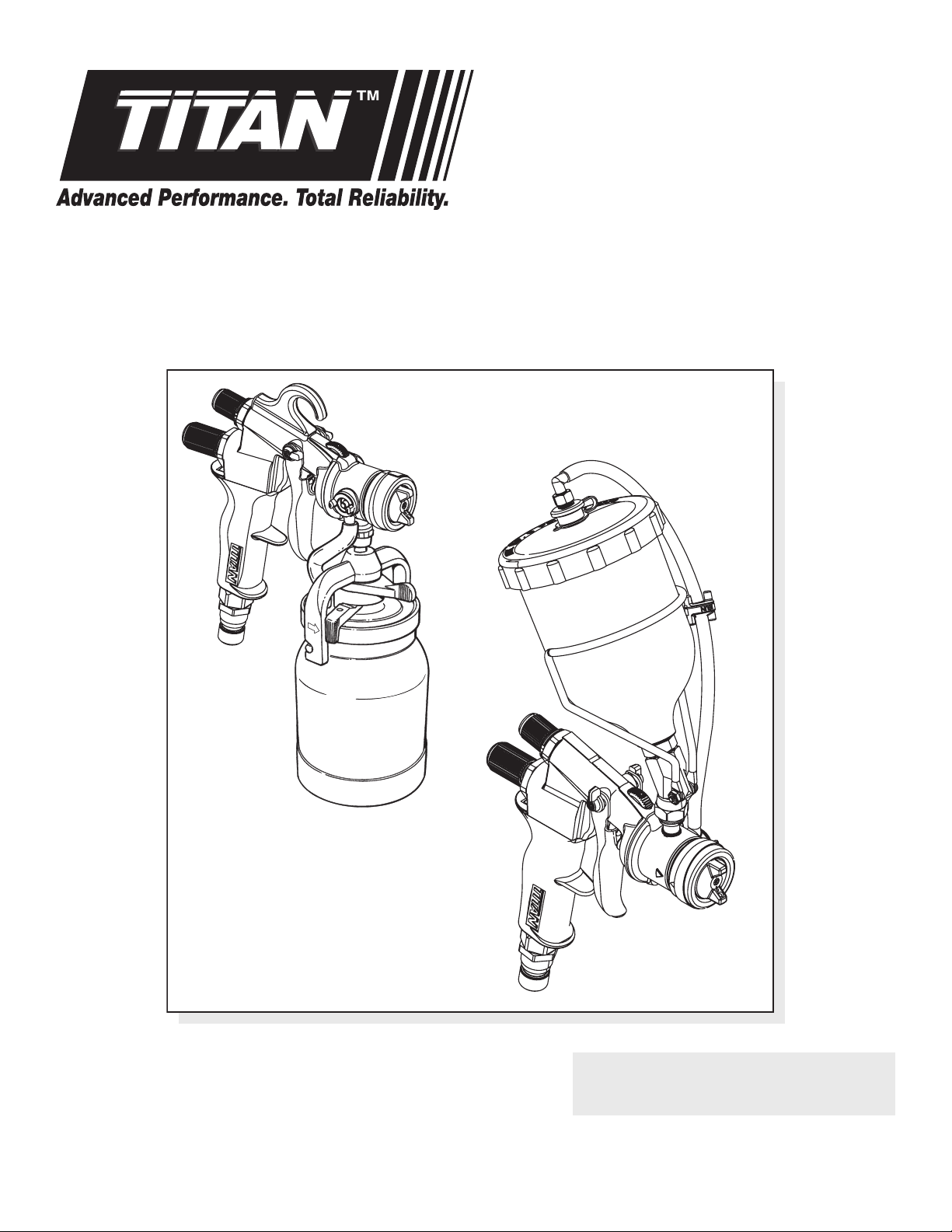
CAPSPRAY Maxum Elite
HVLP Spray Gun
Model 0524027
Model Number: 0524027
0524052
U.S. Patent No. 5,655,714
D616,527
Other patents pending
Model 0524052
NOTE: This manual contains important
warnings and instructions. Please read
and retain for reference.
0515 • © Titan Tool Inc. All Rights Reserved. Form No. 0524838J
Page 2
Important Safety Information
Read all safety information before operating the
equipment. Save these instructions.
Indicates a hazardous situation which, if not avoided,
could result in death or serious injury.
To reduce the risks of re or explosion, electrical shock
and the injury to persons, read and understand all
instructions included in this manual. Be familiar with the
controls and proper usage of the equipment.
HAZARD: GENERAL
Can cause severe injury or property damage.
PREVENTION:
• Read all instructions and safety precautions before operating any
equipment.
• Follow all appropriate local, state, and national codes governing
ventilation, re prevention, and operation.
• The United States Government Safety Standards have been adopted
under the Occupational Safety and Health Act (OSHA). These
standards, particularly Part 1910 of the General Standards and Part
1926 of the Construction Standard should be consulted.
• Use only manufacturer authorized parts. User assumes all risks
and liabilities when using parts that do not meet the minimum
specications and safety devices of the manufacturer.
• Before each use, check all hoses for cuts, leaks, abrasion or bulging
of cover. Check for damage or movement of couplings. Immediately
replace the hose if any of these conditions exist. Never repair a hose.
Replace it with an identical replacement hose.
• Do not spray outdoors on windy days.
• Wear clothing to keep paint o skin and hair.
• Never aim the spray gun at any part of the body.
HAZARD: EXPLOSION HAZARD DUE TO
INCOMPATIBLE MATERIALS
Will cause property damage or severe injury.
PREVENTION:
• Do not use materials containing bleach or chlorine.
• Do not use halogenated hydrocarbon solvents such as bleach,
mildewcide, methylene chloride and 1,1,1 - trichloroethane. They are
not compatible with aluminum.
• Contact your coating supplier about the compatibility of material with
aluminum.
HAZARD: EXPLOSION OR FIRE
Solvent and paint fumes can explode or ignite. Property
damage and/or severe injury can occur.
PREVENTION:
• Provide extensive exhaust and fresh air introduction to keep the air
within the spray area free from accumulation of ammable vapors.
• Avoid all ignition sources such as static electric sparks, open ames,
pilot lights, and hot objects. Connecting or disconnecting power
cords or working light switches can make sparks.
• Do not smoke in spray area.
• Fire extinguisher must be present and in good working order.
• The power cord must be connected to a grounded circuit.
• Follow the material and solvent manufacturer’s safety precautions and
warnings.
• Use extreme caution when using materials with a ashpoint below
100° F (38° C). Flashpoint is the temperature that a uid can produce
enough vapors to ignite.
• Plastic can cause static sparks. Never hang plastic to enclose a spray
area. Do not use plastic drop cloths when spraying ammable
materials.
HAZARD: HAZARDOUS VAPORS
Paints, solvents, insecticides, and other materials can
be harmful if inhaled or come in contact with the body.
Vapors can cause severe nausea, fainting, or poisoning.
PREVENTION:
• Use a respirator or mask if vapors can be inhaled. Read all instructions
supplied with the mask to be sure it will provide the necessary
protection.
• Wear protective eyewear.
• Wear protective clothing as required by coating manufacturer.
HAZARD: SKIN BURN INJURY
Heated parts can cause severe skin burn injury.
PREVENTION:
• Quick disconnect ttings on the hose and spray gun become hot
during use. Avoid skin contact with quick disconnect ttings
when they are hot. Allow quick disconnect ttings to cool before
disconnecting the spray gun from the hose.
Table of Contents
Safety ................................................................................................ 2
Service .............................................................................................. 3
Introduction ..................................................................................... 3
Split Design ........................................................................................................ 3
Using an HVLP Spray Gun ............................................................ 4-5
Preparing to Spray ........................................................................................... 4
Selecting a Spray Pattern .............................................................................. 4
Spray Pattern Size ............................................................................................ 4
Adjusting the Material and Air Flow ......................................................... 4
Spraying .............................................................................................................. 5
Adjusting the Swivel Tube ............................................................................ 5
Cleaning your Spray Gun ................................................................ 5
Maintenance .................................................................................6-7
Adjusting the Packing Nut............................................................................ 6
Replacing the Needle Packing and Air Valve Seals .............................. 6
Replacing the Gun Head Seal and Gun Body O-ring ........................... 7
Replacing the Check Valve Retainer, Valve Seal,
and Air Tube ...................................................................................................... 7
Replacing the Air Flow Valve O-ring ......................................................... 8
Replacing the Cup Gasket ............................................................................. 8
Using a Pressure Feed System ........................................................ 8
Converting the Gun to Pressure Feed ...................................................... 8
Connecting to a 2-Quart Remote Pressure Pot System ..................... 8
Converting to Top Feed .................................................................. 9
Converting the Gun from Non-Bleeder to Bleeder ....................... 9
Choosing a Projector Set ............................................................... 10
Changing a Projector Set ............................................................................10
Optional Accessories ..................................................................... 10
Material reduction/projector set chart ........................................ 11
Troubleshooting ............................................................................ 11
Parts List ....................................................................................32-34
Spray gun assembly ............................................................................... 32-33
Cup assembly ..................................................................................................34
Top feed cup assembly ................................................................................35
Français .......................................................................................... 12
Español ........................................................................................... 22
Warranty ........................................................................................ 36
2 © Titan Tool Inc. All rights reserved.
English
Page 3
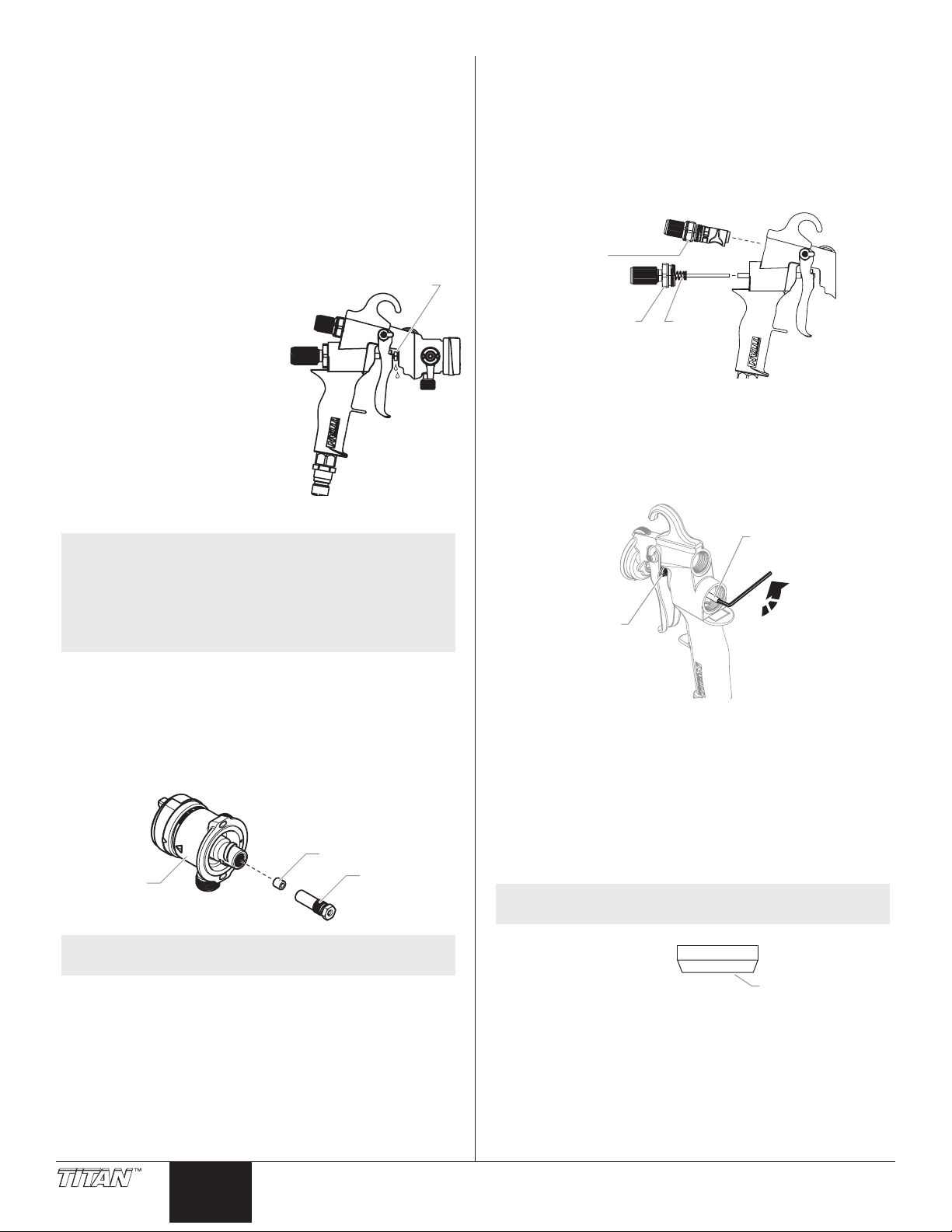
Service
Ma
Air ow
t cup
Gun rear
Gun head
Should your HVLP spray gun need service during the warranty period,
return the unit and the proof of purchase to the distributor where it
was purchased. At our option, the unit will be repaired or replaced. In
a continued commitment to improve quality, we reserve the right to
make component or design changes when necessary.
Introduction
These spray guns are designed for use in a High Volume/Low Pressure
(HVLP) painting system.
With an HVLP system, the highest quality professional nish can be
achieved with little preparation or setup time. HVLP systems are
not intended to replace airless systems. Instead, they are meant to
compliment airless by improving the nal nish on the substrate,
minimizing waste, and reducing labor time. In addition to enhancing
protability, HVLP systems are compliant with the most stringent
transfer eciency requirements.
The HVLP spray guns described in this manual include the turbine
cup gun and the turbine top feed gun. Please review all the
information contained in this manual before operating an HVLP
system.
NOTE: The general operation and maintenance of each style
Packing nut
Check valve
of HVLP spray gun are the same. For illustration
purposes, the turbine cup gun is pictured. However,
any information specic to a style of gun is described
where necessary. A parts listing for each style of gun
is included near the back of this manual.
adj. knob
terial ow
adj. knob
Trigger
release
Trigger
Air Inlet
Hook
Lever
Air cap ring
Air cap
Fluid inlet
Cup locking
lever
1-Quar
assembly
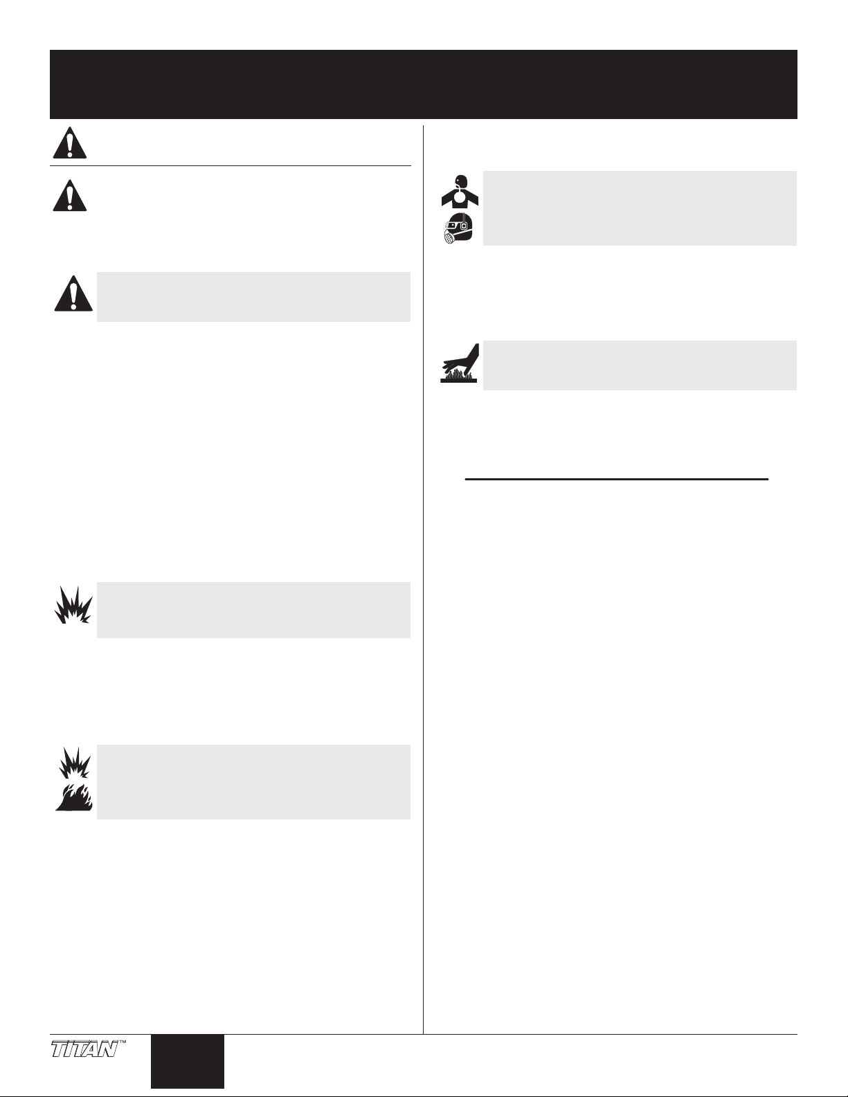
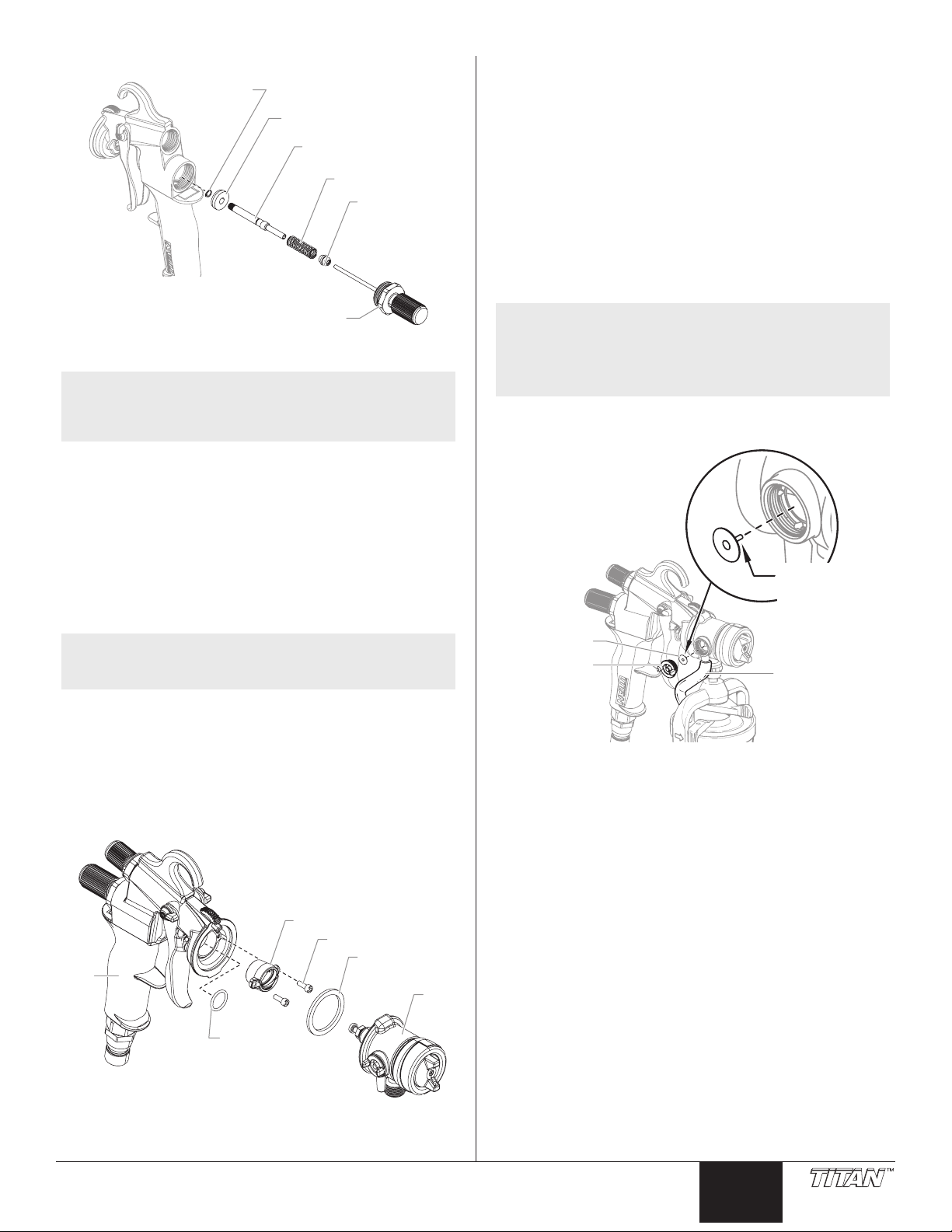
Split Design
This HVLP spray gun has a split-gun design that allows for easier
cleaning and disassembly. The two sections are the gun head and
gun rear.
To separate the two halves of the HVLP spray gun, follow the steps
below.
1. Make sure the air hose is removed from the air inlet of the
spray gun.
2. Swivel the trigger releases on
both sides of the spray gun so
they are pointing up.
3. Push the lever toward the rear of
the gun to unlock the two gun
halves.
4. While looking at the rear of the
spray gun, turn the gun rear counterclockwise to remove it
from the gun head.
Needle
NOTE: The needle will remain inside the gun head. Be sure
not to remove unless instructed.
Swivel tube
lever
NOTE: The hook on top of the gun body can be easily
© Titan Tool Inc. All rights reserved. 3
removed or reversed. Slide the hook toward the rear
of the gun to remove it.
To join the two halves of the HVLP spray gun, follow the steps below.
1. Make sure the trigger releases on both sides of the spray gun
are pointing up (toward the gun hook).
2. With the gun rear oriented upside down, bring the two halves
together. While looking at the rear of the spray gun, turn the
trigger section clockwise until it snaps back into place with the
gun head.
3. Swivel the trigger releases on both sides of the spray gun so
that they are pointing toward the gun head.
English
Page 4
Using an HVLP Spray Gun
Air cap tabs
pattern
tip position
pattern
tip position
Vertical
pattern
tip position
adjustment knob
Air ow
adjustment knob
Preparing to Spray
1. Release the cup locking lever and remove the cup.
2. Make sure that the cup and the cup gasket is clean and in
position. Fill the cup with the desired painting material.
3. Place the cup on the spray gun and tighten the cup locking
lever.
4. Attach the air supply hose to the air inlet tting at the bottom
of the gun handle.
5. Turn on the air supply.
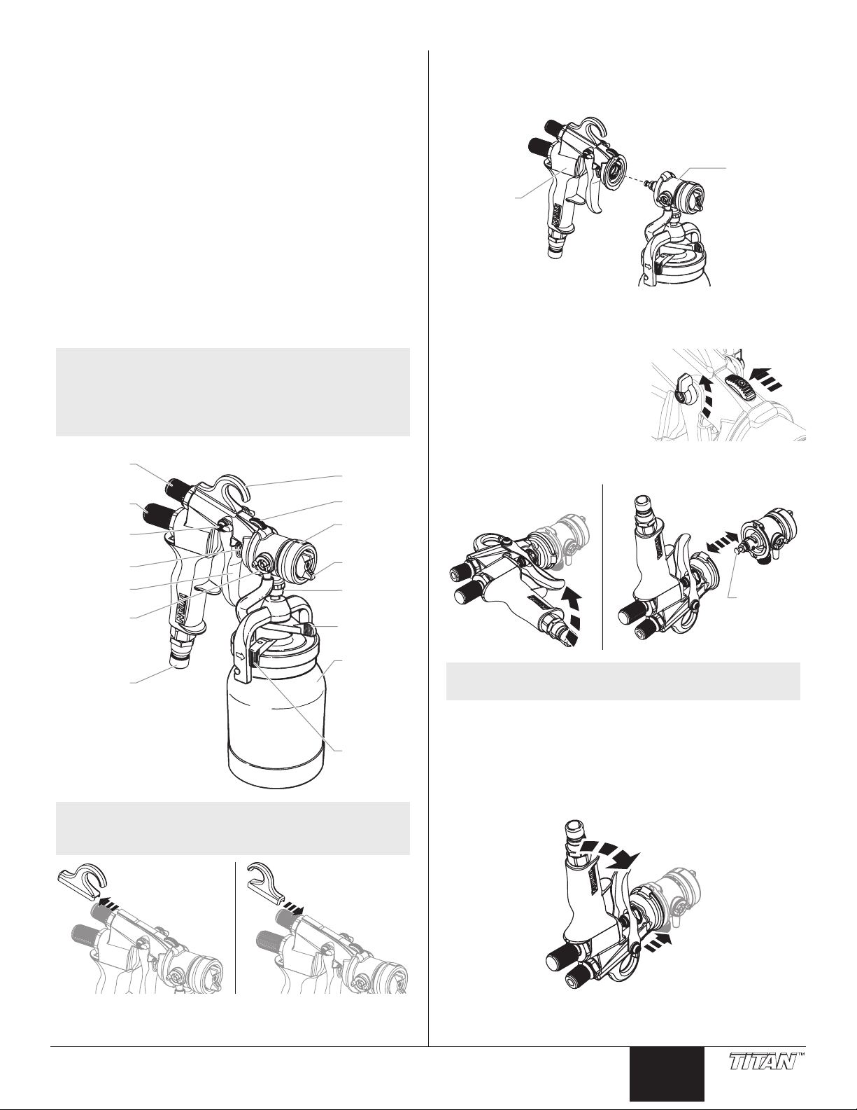
Selecting a Spray Pattern
The spray pattern is adjusted by turning the air cap into either a
vertical, horizontal, or diagonal position. To turn the air cap, grasp
the two front tabs and twist. Never trigger the gun while adjusting
the spray pattern.
Spray Pattern Size
To change the spray pattern size without changing the spray pattern
shape, turn the air cap ring.
Air Cap Ring
Bigger
Pattern
(b)
(a)
Smaller
Pattern
NOTE: An ideal starting point is when the triangle mark on
Turning the ring clockwise will make the pattern bigger. Turning the
ring counterclockwise will make the pattern smaller. As you reduce
the spray pattern size, you will need to move closer to the surface.
the air cap ring (a) is aligned with the triangle mark
on the gun head (b).
Adjusting the Material and Air Flow
Each individual job and material may require slight adjustments in
the material ow and air ow.
Turn the material ow adjustment knob clockwise for less uid and
counterclockwise for more uid.
Vertical
Diagonal
Horizontal
Horizontal
Round
Material ow
More
uid
Turn the air ow adjustment knob to adjust for more or less air. Set
the mark on the knob to the left for maximum airow. Remember to
test the spray on a piece of scrap wood or cardboard before using.
Maximum Minimum
+
Less
uid
-
4 © Titan Tool Inc. All rights reserved.
English
Page 5

Spraying
Correct
Begin
pass
pass
gun
trigger
stroke
Incorrect
Cup Locking Lever
Hold the spray gun between 1 and 8 inches from the spraying
surface, depending on the size of the spray pattern that you need.
The closer to the surface you hold the gun, the smaller the spray
pattern.
Keep the gun at right angles to the spraying surface in order to apply
an even coat of material. If you keep the spray gun moving at a
smooth and constant speed, the spray material is less likely to run or
sag.
Turn swivel tube lever
fully counterclockwise
when spraying up.
The arrow on the
counterclockwise side
of the bridge corresponds
with the position of the
swivel tube.
Trigger
Always squeeze the trigger of the spray gun after you begin your
spray pass and release it before the pass is done. For best results,
make the spray passes about 20 inches long and overlap each pass
by 4 or 5 inches. Remember to keep the gun at right angles to the
spraying surface.
Even
Release
End
Adjusting the Swivel Tube
The adjustable swivel tube on your spray gun lets you get the most
out of the material in your cup no amatter at what angle you need to
spray.
If you are holding your spray gun angled down, turn the swivel tube
lever fully clockwise.
NOTE: An arrow on each side of the bridge indicates the
direction that the swivel tube is pointing when the
swivel tube lever is in its fully clockwise or fully
counterclockwise position.
NOTE: The swivel tube lever is directly below the cup
locking lever. The cup locking lever secures the cup
to the spray gun.
Swivel Tube Lever
Cleaning the Spray Gun
It is very important to clean your HVLP spray gun thoroughly after
each use.
1. Empty the spray material from the cup.
2. Pour a small amount of the appropriate solvent in the cup and
attach the cup to the spray gun.
3. Shake and spray the gun in a well ventilated area.
NOTE: Do not restrict the nozzle when cleaning. Back
ushing of the system is not necessary.
4. Repeat the steps above until the solvent appears clear.
5. Wipe the interior/exterior of the cup and the spray gun with
the appropriate solvent until it is clean.
6. Separate the gun head from the gun rear (see instructions
on page 3). Remove the needle, uid nozzle, and air cap and
clean them thoroughly. Make sure that the air holes and
material passages are completely clean. Never use metal tools
or picks to clean the air cap or nozzle.
IMPORTANT: Any attempt to remove the fluid inlet fitting will
result in damage to the gun body and void the warranty.
Turn
swivel tube lever
fully clockwise
when spraying
If you are holding the spray gun angled up, turn the swivel tube lever
fully counterclockwise.
© Titan Tool Inc. All rights reserved. 5
down.
NOTE: Remove the needle packing only when replacing
with a new needle packing. Do not remove the
needle packing for cleaning.
7. Disassemble, clean, and dry the check valve and air tube after
each use.
IMPORTANT: DO NOT clean the air tube with hot solvents such as
lacquer thinner. Hot solvents will damage the air tube.
NOTE: Lubricate all of the threaded parts on the spray
gun with petroleum jelly when you put them
back together. This will help keep them working
properly.
IMPORTANT: Do not use any lubricants containing silicone.
Silicone can cause problems when used with some paints.
English
Page 6
Maintenance
Gun head
ing nut
valve nut
t
bushing
SIDE VIEW
Fr
Beveled Side
Perform the following maintenance procedures to keep your HVLP
spray gun working properly. New parts can be obtained by ordering
the HVLP Gun Repair Kit, part number 0279911.
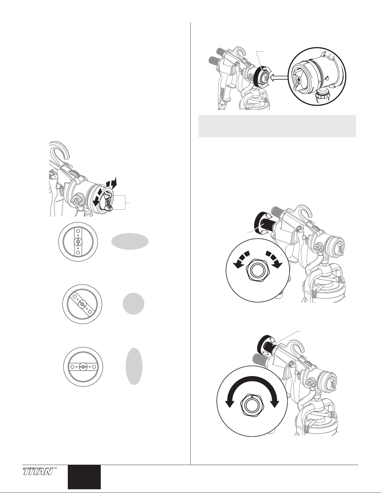
Adjusting the Packing Nut
If material leaks from around or through the packing nut, readjust the
packing nut.
1. Disconnect the air hose from the air inlet and remove the cup
assembly.
2. Pull the trigger all the way back and hold.
3. Tighten the packing nut using a 3/8 inch wrench until the
needle remains retracted inside the nozzle when you release
the trigger.
4. Loosen the packing nut slowly
until the needle moves freely
back into position in the nozzle.
Once you have adjusted the nut,
reconnect the air hose and the cup
assembly. Squeeze the trigger to see if
the leaking has stopped. If it has not,
make sure the packing nut is as tight as
possible, while allowing the needle to
move freely. If adjusting the packing
nut does not stop the leak, replace the
packing.
Replacing the Needle Packing
and Air Valve Seals
NOTE: Remove the needle packing only when replacing
with a new needle packing. Do not remove the
needle packing for cleaning.
The needle packing and the air valve seals can be
replaced separately. If you are replacing only one of
them, use the appropriate steps from the following
procedures.
Packing Nut
B) Removing the Needle and Housing
1. Disconnect the air hose from the air inlet.
2. Separate the gun head from the gun rear (see instructions on
page 3). The needle will remain in the gun head.
3. Loosen the air ow valve nut and remove the air ow
adjustment knob and the air ow valve nut to allow access to
the material ow adjustment housing.
4. Loosen and remove the material ow adjustment housing,
seal, and spring using a wrench.
Air ow
Material
Adjustment
Housing
5. Insert an 1/8 inch hex wrench into the back of the needle
guide shaft.
6. Hold the trigger bushing with a small pliers and turn the 1/8
inch hex wrench counterclockwise to remove the retaining
nut.
7. Pull the needle guide shaft out of the gun body. Do not lose
the trigger bushing.
Trigger
Seal and
spring
Needle
guide shaf
A) Removing / Replacing the Packing
1. Separate the gun head from the gun rear (see instructions on
page 3). The needle will remain in the gun head.
2. With the two sections of the gun still separated, remove the
needle.
3. Remove the packing nut using a 3/8 inch wrench.
4. Remove the packing from the packing nut.
Packing
Pack
NOTE: Make sure all of the old packing is removed before
5. Place the new packing into the packing hole.
6. Thread the packing nut one turn into the packing hole. Do
7. Replace needle into packing nut.
8. Tighten the packing nut securely using a 3/8 inch wrench,
9. Reassemble the gun head into the gun body.
10. Pull the trigger to make certain the needle moves freely. If
installing the new packing.
not tighten.
then loosen the packing nut a quarter turn.
the needle sticks, loosen the packing nut. If the packing leaks,
tighten the packing nut.
C) Replacing the Air Valve Seals
1. Remove the old rear air valve seal. It may stay on the end
of the needle guide shaft spring or in the material ow
adjustment housing.
2. Slide the new rear seal into the material adjustment housing.
3. Remove the front seal retaining clip using a snap-ring pliers.
4. Slide the old front air valve seal o of the needle guide shaft.
5. Place the new front air valve seal on the needle guide shaft
with the beveled side facing the gun.
NOTE: Make sure that the new front air valve seal looks like
the one that was just removed.
ont Air Valve Seal
6 © Titan Tool Inc. All rights reserved.
English
Page 7
6. Snap the front seal retaining clip onto the needle guide shaft.
Front seal
adjustment housing
head
body
retainer /
lve stem should
retaining clip
Front air valve seal
Needle guide shaft
Spring
Rear air
valve seal
Material ow
7. Reassemble the parts into the gun rear by reversing the steps
above.
NOTE: When replacing the needle guide shaft and the
trigger guide, secure the trigger guide in an
adjustable wrench. This will hold it in place while
the needle guide shaft is reinstalled.
Replacing the gun head seal and gun body O-ring
1. Remove the spray gun head from the gun body (see
instructions on page 3).
2. Pull the old gun head seal from the gun body. Do not install
the new one yet.
3. Using a 7/64 in hex wrench, remove the two gun body insert
screws. Remove the gun body insert.
4. Remove the gun body O-ring from the gun body. You may
need to use a needle-nose pliers or some other long, thin
object to remove it from the gun body.
Replacing the Check Valve Retainer, Valve Seal and
Air Tube
The check valve is a one-way valve designed to allow air into the
cup, pressurizing the cup’s contents. Because it is a one-way valve, it
prevents paint from seeping up the air tube into the air passages of
the gun. It also eliminates any delay in material ow when the gun is
triggered by maintaining pressure in the cup.
The check valve rotates open easily for cleaning. It contains a valve
seal that can be removed and cleaned with soap and water for
waterborne materials or a compatible solvent for other materials. To
replace the the valve seal and/or the air tube:
1. Unscrew the check valve retainer by turning it
counterclockwise.
2. Pull the valve seal out of the gun head. Clean or replace the
valve seal.
NOTE: The check valve area inside the gun head should
also be cleaned of any accumulated spray material.
DO NOT use anything metal or abrasive to clean the
check valve area as it will scratch the metal surface,
and the valve seal will not seal properly.
3. Reinstall the valve seal. Insert the stem of the valve seal into
the hole of the gun head.
Va
be facing toward
the gun
NOTE: Make sure this area of the gun body is free from all
5. Lubricate the new O-ring with petroleum jelly and install into
6. Replace the gun body insert and secure with the gun body
7. Install the new gun head seal into the gun head body as
8. Reassemble the spray gun head onto the gun body (see page
Gun
spray material residue before reinstalling the new
gun body O-ring.
the gun body.
insert screws.
shown.
3).
Gun body insert
Screws
Gun head
seal
Gun body
O-ring
Gun
Valve seal
Check valve
O-ring
4. Screw the new or cleaned check valve retainer / o-ring back
into the gun head by turning it clockwise.
5. To replace the air tube, pull it from the nipples on both the
gun head and the cup assembly. Replace with a new tube.
Air tube
© Titan Tool Inc. All rights reserved. 7
English
Page 8
Replacing the Air Flow Valve O-ring
Adjustment
Cup Gasket
Swivel Lever
1. Using a wrench, loosen the air ow valve nut and remove the
air ow adjustment knob assembly.
2. Using a screwdriver, remove the adjustment knob screw.
Separate the adjusment knob from the air ow valve nut. Be
careful not to lose the washer.
3. Separate the air ow valve from the air ow valve nut. The air
ow valve O-ring is located on the air ow valve.
4. Remove the air ow valve O-ring from the air ow valve.
5. Lubricate the new O-ring with a small amount of petroleum
jelly, and replace into the gun body.
6. Reassemble the air ow adjustment knob assembly:
a. Insert the air ow valve into the rear of the spray gun.
b. Place the air ow valve nut over the air ow valve and
thread it into the rear of the gun. Tigthen with a wrench.
c. Turn the air ow valve slightly counterclockwise until it
does not turn any further.
d. Install the washer.
e. Place the adjustment knob over the air ow valve. The
mark on the knob should be in the 9:00 o’clock position
(all the way to the left).
f. Secure the adjustment knob with the screw. Tighten
with a screwdriver.
Using a Pressure Feed System
To increase spray time between material rells, your HVLP spray
gun can be connected to a larger material pressure pot and air
compressor.
Converting the Gun to Pressure Feed
Before using a pressure feed system, the spray gun must be
converted to a pressure fed gun.
1. Loosen the retaining nut using a wrench and remove the one
quart cup assembly.
2. Pull the air tube o of the air tube tting on the spray gun.
Air tube
Retaining nut
Air ow valve O-ring
Air ow valve
Air ow valve nut
Washer
knob
Screw
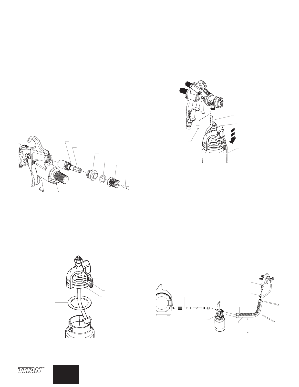
Replacing the Cup Gasket
The cup gasket must be replaced periodically due to normal wear. It is
important to inspect the cup gasket during each cleaning.
1. Release the cup locking lever.
2. Hold the cup and twist the spray gun in the direction
indicated by the arrows on the bridge.
3. Lift the spray gun away from the cup.
4. Pull the worn cup gasket out of the lid.
5. Press a new cup gasket into the lid.
6. Place the spray gun onto the top of the cup.
Bridge
Cup Locking
Lever
Pressure cap
Cup assembly
3. Place the pressure cap over the nipple on the gun head.
Connecting to a 2-Quart Remote Pressure Pot
1. Convert the gun to pressure feed.
2. Connect hoses:
a. Make sure turbine is turned OFF and unplugged.
b. Attach remote pressure pot to the turbine via the hose
conguration shown below.
c. Tighten the air hose connections by hand.
d. Tighten the uid hose connections with an adjustable
wrench.
1) Turbine
2) 7.5m air hose
3) Female quick-disconnect coupling
4) 2-quart pressure tank assembly
5) 1.5m air whip hose
6) 1.5m uid whip hose
7) Hose straps
8) Female quick-disconnect coupling
9) Spray gun
9
Lid
2
3
1
8
5
4
6
7. Turn the spray gun opposite the direction indicated by the
arrows on the bridge until the pegs on the cup are in the
notches of the bridge.
8. Tighten the cup locking lever.
8 © Titan Tool Inc. All rights reserved.
English
7
Page 9
Converting to Top Feed
adjustmen
Air inlet
The cup is designed for a maximum working pressure
of 6 PSI (0.41 bar). Pressures higher than 6 psi can
result in cup leakage, damage to the equipment, and/
or potential injury to the user.
The top feed HVLP spray gun is designed for use in special
applications such as spraying in conned areas. The position of
the cup gives the top feed gun the ability to spray downward and
overhead. When spraying with the top feed gun, remember the
following tips for the best results. Keep the cup pressurized at all
times when spraying. Attempting to gravity feed the material will
slow or stop the ow of material at the nozzle.
NOTE: It is recommended that the gun hook be removed
whenever using the top feed cup assembly.
To set up the spray gun for top feed delivery:
1. Loosen the retaining nut using a wrench and remove the one
quart cup assembly.
2. Pull the air tube o of the air tube tting on the spray gun.
3. Separate the gun head from the gun rear (see instructions
on page 3). Reassemble gun head upside-down so uid inlet
tting on gun head points upward to accept the top feed cup
assembly.
4. Remove the gun hook and thread the retaining nut of the topfeed cup assembly onto the uid inlet of the gun head. Rotate
the stand away from the cup and set the gun assembly on a
level surface.
5. Using an adjustable wrench, secure the retaining nut, making
sure the gun/cup assembly stays in a level position. The cup
should end up in a vertical position when supported by the
stand.
6. Connect the air tube to the air tube tting on the spray gun.
IMPORTANT: The gun, when converted to top-feed, will not
stand on its own. Make sure to use the stand when filling. Do not
lay the gun on its side when it is filled with material. Do not hang
the gun by its hook when lled with material.
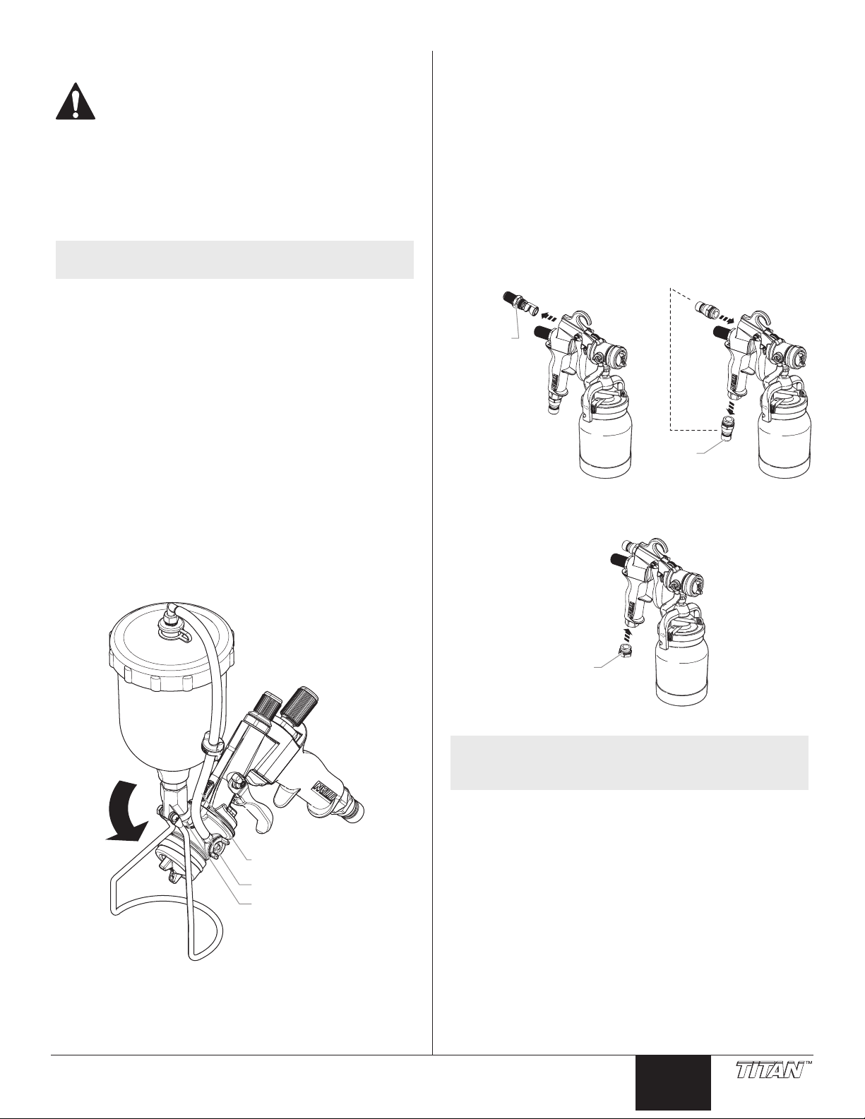
Converting the gun from Non-Bleeder to
Bleeder
Your HVLP spray gun can be converted from a non-bleeder to a
bleeder setup. Bleeder setup provides more atomizing power for
higher viscosity materials, such as latex and enamels. Bleeder setup
can make it easier to spray in conned spaces, such as inside cabinets,
because the air hose is moved to the back of the gun.
To convert a spray gun to bleeder setup:
1. Remove the air ow adjustment knob from the rear of the gun
using a wrench.
2. Remove the air inlet tting from the bottom of the gun handle
using a wrench.
3. Thread the air inlet tting into the air ow adjustment knob
location at the rear of the gun. Secure the tting in place.
Air ow
t
knob
Air inlet
tting
4. Thread the air inlet plug (shipped loose with the gun literature
pack) into the air inlet at the bottom of the gun handle.
Secure the plug in place.
Air tube
Air tube tting
Fluid inlet
© Titan Tool Inc. All rights reserved. 9
plug
5. Attach the air hose to the relocated air inlet tting.
NOTE: In bleeder setup, the removal of the air ow
adjustment knob causes the air supply to be on at all
times when the air hose is attached to the gun.
English
Page 10

Choosing a Projector Set
Fluid nozzle
Air cap
Your HVLP spray gun should be tted with the proper projector set
for the type of work you will be performing. A projector set consists
of a needle assembly, a uid nozzle, and an air cap.
Needle assembly
You should choose a projector set based on two things: the type of
material to be sprayed and the nish desired.
The chart on the following page should help you to make the right
choice.
Changing a Projector Set
1. Remove the air cap ring, air cap, and spring plate.
Air cap ring
Air cap
Spring plate
2. Remove the uid nozzle.
Optional Accessories
Part Number Description
0524293 Projector set, #2 complete
0524294 Projector set, #3 complete
0524295 Projector set, #4 complete
0524296 Projector set, #5 complete
0524297 Projector set, #6 complete
0524298 Projector set, #7 complete
0276449 Air cap, #2
0276452 Air cap, #3
0276455 Air cap, #4
0276458 Air cap, #5
0276417 Air cap, #6
0524401 Air cap, #7
0276446 Nozzle, #2
0276451 Nozzle, #3
0276454 Nozzle, #4
0276457 Nozzle, #5
0276418 Nozzle, #6
0524363 Nozzle, #7
0524282A Needle assembly, #2
0524283A Needle assembly, #3
0524284A Needle assembly, #4
0524285A Needle assembly, #5
0524286A Needle assembly, #6
0524287A Needle assembly, #7
0508124 Cover, clip-on, 1 quart
0524188 Tip accessory kit
0524189 Deluxe tip accessory kit
0524271A Cup assembly
0524045 Top feed cup assembly
Repair Kits
Part Number Description
0276257 Check valve membrane kit
(includes 10 membranes)
0297052 Gasket, cup, white (includes 6 gaskets)
0524507 Nozzle key
0279911 HVLP gun repair kit*
*Includes:
• air valve seal (0277486)
• rear air valve seal (0275501)
• needle packing (0275579)
• check valve retainer assembly (0529220)
• gun body o-ring (0524618)
• air ow valve o-ring (0508403)
• check valve seal (0276415)
• cup gasket (0277495)
• gun head seal (0524503)
* See parts lists on page 32-35 for part locations.
3. Separate the gun head from the gun rear (see instructions on
page 3).
4. Remove the needle.
IMPORTANT: If the needle does not slide out easily, loosen
the packing nut to prevent the needle or packing from being
damaged.
5. Install the new projector set in reverse order.
10 © Titan Tool Inc. All rights reserved.
English
United States Sales & Service
Phone:
1-800-526-5362
Fax:
1-800-528-4826
1770 Fernbrook Lane
Minneapolis, MN 55447
www.titantool.com
Page 11

Material Reduction/Projector Set Chart
Before spraying, the material being used must be thinned with an appropriate solvent and the proper projector set must be installed. It is
always best to follow the material manufacturers recommendations and thinning procedures.
There are two simple methods of measuring the proper thickness of a material:
1. Dip a paint stick into the material and remove it, watching carefully as the material runs o. When the material begins to form drops, the
drops should fall about 1 second apart.
2. Use a viscosity cup (P/N 0153165). Dip the cup into the material and remove it. Use a watch or clock to time how long the material drains
from the cup in a continuous stream. Once the continuous stream breaks, stop timing and refer to the table below. Add the appropriate
solvent and continue testing until the proper thickness is reached for the type of material you are using.
Material % of reduction Time Solvent Projector Set
Latex .......................................... 20-25% ............................................... 30-35 sec. ...................Water ..............................................................5
Oil ............................................... 10-20% ............................................... 20-30 sec. ................... Mineral Spirits .............................................4
Epoxy.........................................1-10% ................................................. 30-35 sec. ...................Mfg. Recommendations ..........................5
Clear wood nish .................. Full strength .............................................................................Mfg. Recommendations ..........................4
Varnish ...................................... Mfg. Recommendations ...................................................... Naphtha.........................................................3
Polyurethane .......................... 10% ..................................................... 18-22 sec. ................... M.E.K. ..............................................................3
Sealer.........................................Full strength .............................................................................Mineral spirits ..............................................3
Oil-based primer ................... 15-20% ............................................... 30-35 ........................... Mineral spirits ..............................................4
Fast-dry enamel ....................25% ..................................................... 20-25 ........................... Mineral spirits ..............................................4
Stain ........................................... Full strength ............................................................................. Mfg. Recommendations ..........................3
Metal primer ........................... 15% ..................................................... 25-30 sec. ................... Mineral spirits .............................................. 4
Industrial enamel .................. 15% ..................................................... 30-35 sec. ................... Mineral spirits ..............................................4
Aluminum paint .................... Full strength .............................................................................Mineral spirits ..............................................4
Lacquer sealer ........................ Mfg. Recommendations .............. 18-22 sec. ................... Lacquer thinner .......................................... 3
Lacquer .....................................50% ..................................................... 18-22 sec. ................... Lacquer thinner .......................................... 3
Troubleshooting
Problem
A. Little or no paint ow
B. Paint leaking
C. Paint is backing up past the
check valve
D. Poor spray pattern
E. Pulsating spray
F. Pattern is heavy in the middle
G. Gun spitting paint
H. Paint build up on the air cap
I. Too much overspray
Cause
1. Dried paint blocking uid nozzle
2. No air pressure in paint cup or pot
3. Check valve in air tube plugged
4. No uid pressure
5. Blockage in material hose
1. Improper size needle or nozzle
2. Damaged needle or nozzle
3. Loose nozzle
4. Loose packing nut
5. Needle not closing properly
1. Gun is being tilted too much when it is not
spraying
2. Check valve leaks
1. Air holes in air cap ears are clogged
2. Nozzle is clogged
3. Damaged nozzle or needle
1. Loose or damaged packing
1. Too much uid pressure
1. Valve in air tube is not operating properly
2. Material too thick
3. Projector set is too small.
1. Improper adjustment of cap
1. Air pressure too high
2. Material too thin
3. Spray gun too far from surface
Solution
1. Disassemble and clean
2. Inspect air tube, cup or pot gasket, clean or replace.
3. Clean or replace the check valve assembly
4. Check material supply
5. Clean by ushing with solvent
1. Replace
2. Replace
3. Tighten
4. Tighten
5. a) Loosen packing nut
b) Replace needle spring
c) Remove dried paint from needle
1. Tilt the gun only when spraying
2. Clean or replace the check valve
1. Remove and clean air holes
2. Clean with appropriate solvent
3. Remove and replace
1. Tighten or replace
1. Reduce pressure
1. Replace valve assembly
2. Thin material
3. Install the proper projector set.
1. Adjust the air cap properly so that paint ows freely
through the cap
1. Reduce air pressure
2. Add unthinned paint
3. Move closer
© Titan Tool Inc. All rights reserved. 11
English
Page 12

Consignes de sécurite important
Lire toutes ces consignes avant d’utiliser l’appareil.
Garder ces consignes.
Indique une situation à risque, laquelle, si elle n’est pas évitée,
peut entraîner des blessures graves, voire la mort.
Pour réduire les risques d’incendie ou d’explosion, de choc
électrique et de blessure, vous devez lire et comprendre les
directives gurant dans ce manuel. Familiarisez-vous avec les
commandes et l’utilisation adéquate de l’équipement.
DANGER : GÉNÉRAUX
Risques de dommages matériels et de blessures graves.
PRÉVENTION :
• Lire toutes les directives et mises en garde avant de faire fonctionner
l’équipement, quel qu’il soit.
• Se conformer à la législation locale, provinciale ou fédérale pour
tout ce qui concerne la ventilation, la prévention des incendies et les
conditions générales d’utilisation.
• Les normes de sécurité adoptées par le gouvernement américain l’ont
été en vertu de sa Occupational Safety and Health Act (OSHA); ces
normes, particulièrement les parties 1910 des normes générales et
1926 des normes de construction, devraient toujours être consultées.
• N’utiliser que les pièces autorisées par le fabricant. L’utilisateur
assume tous les risques et responsabilités lorsqu’il utilise des pièces
qui ne sont pas conformes aux caractéristiques techniques minimales
ainsi qu’aux dispositifs de sécurité du fabricant.
• Vérier, avant toute utilisation, que les exibles ne présentent pas
d’entaille ou de fuite, que le couvercle ne soit pas goné et que les
raccords ne soient pas endommagés. Si le exible a subi l’un des
dommages précités, remplacez-le immédiatement. Ne jamais réparer
un exible d’alimentation. Le remplacer avec un exible identique de
remplacement.
• Ne jamais pulvériser lorsqu’il vente.
• Porter des vêtements pour protéger la peau et les cheveux contre
tout contact avec la peinture.
• On ne doit jamais orienter le pistolet vers une partie du corps.
DANGER : RISQUES D’EXPLOSION PAR INCOMPATIBILITÉ
Peuvent être à l’origine de corporels sérieux ou dommages matériels.
PRÉVENTION :
• Ne pas utiliser de matériaux contenant des agents de blanchiment ou
du chlore.
• Ne pas utiliser des solvants à base d’hydrocarbure halogéné tels que
l’agent anticryptogamique, le chlorure de méthylène et le trichloroéthane-1,1,1. Ces produits ne sont pas compatibles avec l’aluminium.
• Communiquer avec votre fournisseur de revêtement pour connaître la
compatibilité du matériau avec l’aluminium.
DANGER : RISQUES D’EXPLOSION OU D’INCENDIE
Les vapeurs dégagées par le solvant ou la peinture sont
explosives et inammables et peuvent causer des corporels
sérieux ou dommages matériels.
PRÉVENTION :
• Veiller à éviter toute accumulation de vapeurs inammables en vous
assurant que la zone où la pulvérisation a lieu est susamment
ventilée.
• Veiller à éviter la présence de toute source incandescente telle
qu’étincelle électrostatique, amme nue, amme-pilote, objet
brûlant, cigarette et étincelle provenant du branchement ou du
débranchement d’un cordon d’alimentation électrique ou d’un
commutateur.
• Ne pas fumer dans la zone d’épandage.
• Toujours avoir un extincteur en état de fonctionner à portée de la main.
• Le cordon d’alimentation doit être raccordé à un circuit mis à la terre.
• S’assurer de suivre les directives en matière de sécurité et de lire les
mises en garde du fabricant des solvants et des produits utilisés.
12 © Titan Tool Inc. Tous droits réservés.
DES MATÉRIAUX
Français
• S’entourer de toutes les précautions possibles lorsqu’on utilise des
produits ayant un point d’éclair inférieur à 38 °C (100 °F). Le point
d’éclair d’un uide est la température à laquelle les vapeurs émanant du
uide peuvent s’enammer au contact d’une amme ou d’une étincelle.
• Le plastique peut être une source d’étincelles provoquées par
l’électricité statique. Ne jamais utiliser une couverture en plastique
pour fermer une zone d’épandage ni utiliser des toiles de protection en
plastique lors de la pulvérisation de matières inammables.
DANGER : VAPEURS NOCIVES
La peinture, les solvants, les insecticides et autres matériaux
peuvent être nocifs lorsqu’ils sont inhalés ou en contact avec le
corps. Les vapeurs peuvent causer une nausée importante, des
évanouissements ou un empoisonnement.
PRÉVENTION :
• Utiliser un respirateur ou un masque chaque fois qu’il y a des risques
d’inhalation de vapeurs. Lire attentivement toutes les instructions
se rapportant au masque pour vérier que celui-ci vous assure une
protection susante contre les vapeurs toxiques.
• Porter des lunettes de protection.
• Porter des vêtements de protection, conformément aux directives du
fabricant de revêtement.
DANGER : DANGER DE BRÛLURE
Les pièces chauées peuvent causer de graves brûlures cutanées.
PRÉVENTION :
• Les raccords à dégagement rapide du tuyau exible et du pistolet
peuvent s’échauer en cours d’utilisation; il faut alors éviter les
contacts cutanés, en attendant que les raccords refroidissent avant de
séparer le pistolet du tuyau.
Table des matières
Sécurité.........................................................................................................12
Entretien et réparations ..............................................................................13
Introduction .................................................................................................13
Conception divisée ........................................................................................................13
Utilisation d’un pistolet de vaporisation HVLP................................... 14-15
Préparation à la vaporisation .....................................................................................14
Sélection d’une forme de pulvérisation .................................................................14
Aire de pulvérisation .....................................................................................................14
Réglage du débit d’air et de produit .......................................................................14
Pulvérisation ....................................................................................................................15
Réglage du tube orientable .......................................................................................15
Nettoyage du pistolet .................................................................................15
Maintenance .......................................................................................... 16-17
Réglage de l’écrou presse-garniture .......................................................................16
Remplacement de la garniture de pointeau et
des joints de soupape de régulation d’air.............................................................16
Remplacement du joint de la tête du pistolet et
du joint torique de la tête du pistolet.....................................................................17
Remplacement la retenue de clapet anti-retour, du joint de
clapet et de tube d’air ..................................................................................................17
Remplacement du joint torique de la soupape de régulation d’air ............18
Remplacement du joint d’étanchéité du godet .................................................18
Utilisation d’un système d’alimentation sous pression ................................ 18
Modication du pistolet pour alimentation sous pression.............................18
Raccordement récipient système sous pression du deux pintes .................18
Convertissement à l’alimentation par le haut...........................................19
Modication du pistolet non-purgeur en pistolet purgeur .........................19
Choix d’un projecteur .................................................................................20
Échange du projecteur.................................................................................................20
Accessoires optionnels................................................................................20
Réduction du produit/tableau des projecteurs ........................................21
Diagnostic des anomalies ...........................................................................21
Liste de pièces ........................................................................................ 32-34
Ensemble de pistolet ............................................................................................. 32-33
Ensemble godet .............................................................................................................34
Ensemble godet à alimentation par le haut .........................................................35
Garantie limitée ...........................................................................................36
Page 13

Entretien et réparations
Bouton de
Déclenchemen
xation du
godet de 1
Crochet
Arrière du
pistolet
Si le pistolet requiert de l’entretien ou des réparations pendant la
période de la garantie, on doit le retourner, accompagné d’une
preuve d’achat, au distributeur chez qui on l’a acheté. Il sera alors,
selon le choix du fabricant, réparé ou remplacé. Dans le cadre de son
engagement perpétuel envers l’amélioration de la qualité, Titan se
réserve le droit de modier les composants ou la conception de ses
produits si elle le juge nécessaire.
Introduction
Ces pistolets de vaporisation sont conçus pour une utilisation dans
les systèmes de peinture “High Volume/Low Pressure” (HVLP) (grand
volume/basse pression).
Avec un système HVLP, il est possible d’obtenir une nition de très
haute qualité professionnelle avec peu de préparation et de temps
de réglage. Les systèmes HVLP ne sont pas destinés à remplacer
les systèmes sans air. Au contraire ils sont conçus pour compléter
les systèmes sans air en améliorant la nition sur les substrats, en
minimisant les pertes et en réduisant le temps de travail. En plus
d’améliorer la rentabilité, les systèmes HVLP sont compatibles avec
les exigences de rendement de transfert les plus sévères.
Les pistolets de vaporisation HVLP décrits dans ce manuel
comprennent le pistolet à godet et turbine, et le pistolet à turbine
à alimentation supérieure. SVP, consultez toutes les informations
contenues dans ce manuel avant d’utiliser un système HVLP.
NOTA : Le fonctionnement général et la maintenance de chaque
type de pistolet de vaporisation HVLP sont les mêmes.
Pour les besoins des illustrations, seul le pistolet à
godet et turbine est représenté. Cependant, toutes
les informations spéciques à un type particulier de
pistolet sont données où cela est nécessaire. Les listes
de pièces pour chaque type de pistolet sont incluses à la
n de ce manuel.
Conception divisée
Ce pistolet de vaporisation HVLP (grand volume/basse pression) est
d’une conception divisée qui facilite le nettoyage et le démontage.
Les deux sections sont la tête du pistolet et l’arrière du pistolet.
Tête du
pistolet
Pour séparer les deux moitiés du pistolet de vaporisation HVLP, suivre
les étapes suivantes.
1. S’assurer que le boyau d’air est retiré de l’entrée d’air du
pistolet de vaporisation.
2. Orienter les déclenchements
de la détente des deux côtés du
pistolet de vaporisation de façon
à ce qu’ils pointent vers le haut.
3. Pousser le levier vers l’arrière du
pistolet pour déverrouiller les
deux moitiés du pistolet.
4. Tout en regardant à l’arrière du pistolet de vaporisation,
tourner l’arrière du pistolet dans le sens contraire des aiguilles
d’une montre an de le retirer de la tête du pistolet.
NOTA : Le crochet sur le haut du corps de pistolet peut être
réglage du
débit d'air
Bouton de
réglage du
débit de
produit
de la détente
Écrou presse-
anti-retour
Entrée d'air
t
garniture
Détente
Clapet
facilement retiré ou renversé. Glisser le crochet vers
l’arrière du pistolet an de le retirer.
Levier
Bague de
bouchon
d'air
Bouchon
d'air
Entrée du
uide
Levier de
blocage
du godet
Ensemble
litre
Levier
de tube
orientable
NOTA : Le pointeau demeurera à l’intérieur de la tête du
pistolet. S’assurer de ne pas le retirer, à moins que ce
soit indiqué.
Pour joindre les deux moitiés du pistolet de vaporisation HVLP, suivre
les étapes suivantes.
1. S’assurer que les déclenchements de la détente des deux
côtés du pistolet de vaporisation sont orientés vers le haut
(vers l’agrafe du pistolet).
2. Avec l’arrière du pistolet orienté à
l’envers, joindre les deux moitiés.
Tout en regardant à l’arrière du
pistolet de vaporisation, tourner
la section de la détente dans le
sens des aiguilles d’une montre
jusqu’à ce qu’elle soit en place
avec la tête du pistolet.
3. Orienter les déclenchements
de la détente des deux côtés du
pistolet de vaporisation de façon
à ce qu’ils pointent vers la tête du pistolet.
Pointeau
© Titan Tool Inc. Tous droits réservés. 13
Français
Page 14

Utilisation d’un pistolet de vaporisation HVLP
bouchon d'air
horizontale
verticale
circulaire
diagonale
verticale
horizontale
Bague de xation du
du débit de produit
Bouton de réglage
Préparation à la vaporisation
1. Libérer le levier de blocage du godet et démonter le godet.
2. S’assurer que le godet et le joint d’étanchéité du godet soit
propre et à la bonne position. Remplir le godet avec le produit
de peinture désiré.
3. Placer le godet sur le pistolet et serrer le levier de blocage du
godet.
4. Fixer le boyau d’alimentation en air sur le raccord d’entrée
d’air à la partie inférieure de la poignée de pistolet.
5. Activer l’alimentation d’air.
Sélection d’une forme de pulvérisation
On peut modier la forme de pulvérisation en faisant tourner le
bouchon d’air en position verticale, horizontale ou diagonale. Pour
ce faire, saisir les deux pattes avant et tourner. Il ne faut jamais
appuyer sur la détente du pistolet lors de ce réglage.
Pattes du
Aire de pulvérisation
On peut changer l’aire de pulvérisation sans en modier la forme, en
faisant tourner la bague de xation du bouchon d’air.
bouchon d'air
Grande
(b)
(a)
Petite
NOTA : Un point de départ idéal est lorsque le triangle sur la
bague de réglage (a) est aligné avec le triangle sur la
tête du pistolet (b).
En tournant la bague vers la droite, on agrandit l’aire; en la tournant
vers la gauche, on la réduit. À mesure que l’aire rapetisse, on doit
s’approcher de la surface à pulvériser.
Réglage du débit d’air et de produit
Chaque projet peut requérir un léger réglage du débit d’air ou de
produit. Pour ce qui est de ce dernier, le débit diminue lorsqu’on
tourne le bouton de réglage vers la droite et augmente lorsqu’on le
tourne vers la gauche.
Position
Position
Position
Forme
Forme
Forme
Bouton de réglage
Plus de
uide
L’autre bouton sert à augmenter ou à réduire le débit d’air. Si
l’encoche est en position vers la gauche, le débit est maximal. Rappel
: il faut toujours eectuer des essais sur des retailles de bois ou de
carton avant de procéder à la pulvérisation.
Moins
de uide
du débit d'air
14 © Titan Tool Inc. Tous droits réservés.
Français
Maximal Minimal
+
-
Page 15

Pulvérisation
Bonne position
mouvement
mouvement
détente
détente
Mauvaise position
de la vaporisation vers le bas.
Tenir le pistolet à une distance de 2,5 cm (1 po) à 20,3 cm (8 po) de
la surface à pulvériser, selon l’aire de pulvérisation choisie; plus le
pistolet est près de la surface, moins l’aire est grande. Le pistolet
doit être tenu à angle droit par rapport à la surface à pulvériser de
manière à assurer une application uniforme du produit. Si le pistolet
se déplace à vitesse continue et constante, le produit risque moins de
former des gouttes ou des coulures.
Tourner le levier orientable
entièrement dans le sens
anti-horaire lors de la
vaporisation vers le haut.
La èche sur le côté antihoraire de la couronne
correspond à la position
du levier d'orientation.
Début du
Il faut toujours appuyer sur la détente après avoir commencé son
mouvement et la relâcher avant que celui-ci ne se termine. Pour
obtenir de meilleurs résultats, les mouvements de pulvérisation
devraient être longs d’environ 50 cm (20 po) en se chevauchant les
uns les autres de 10 ou 12 cm (4 ou 5 po). Rappel : le pistolet doit être
perpendiculaire à la surface à pulvériser.
Appui
de la
Mouvement
uniforme
Relâche-
ment de la
Fin du
Réglage du tube orientable
Le tube orientable du pistolet permet d’éviter le plus de gaspillage de
produit possible, quel que soit l’angle de pulvérisation.
Si le pistolet est orienté vers le bas, il faut pousser le levier
d’orientation à l’extrême droite.
NOTA : De chaque côté de la couronne, une èche indique
la direction dans laquelle le tube orientable pointe
lorsque le levier du tube orientable est dans la
position extrême de rotation en sens horaire ou
extrême de rotation dans le sens anti-horaire.
NOTA : Le levier orientable est placé directement sous le
levier de blocage du godet. Celui-ci assure la xation
du godet avec le pistolet.
Levier de blocage du godet
Levier d'orientation
Nettoyage du pistolet
Il est important de nettoyer entièrement le pistolet après chaque
utilisation.
1. Vider le godet du produit résiduel.
2. Verser une petite quantité de solvant approprié dans le godet
et xer celui-ci au pistolet.
3. Remuer et vaporiser dans un endroit bien ventilé.
NOTA : Ne pas obturer la buse lors du nettoyage. Un
refoulement dans le système n’est pas nécessaire.
4. Répéter les opérations ci-dessus jusqu’à ce que le solvant reste
clair.
5. Nettoyer l’extérieur/interieur du godet et du pistolet avec un
solvant approprié jusqu’à ce qu’ils soient propres.
6. Séparer la tête du pistolet de l’arrière du pistolet (consulter
les consignes à la page 13). Démonter le pointeau, la buse à
uide et le bouchon d’air et les nettoyer entièrement. S’assurer
que les trous de passage de l’air et les passages de produit
soient bien propres. Ne jamais utiliser de pointes ou d’outils
métalliques pour nettoyer le bouchon d’air et la buse.
IMPORTANT : Toute tentative de démontage du raccord d’entrée
de fluide entraîne des dommages au corps du pistolet et annule
la garantie.
Si le pistolet est orienté vers le haut, il faut pousser le levier
d’orientation à l’extrême gauche.
© Titan Tool Inc. Tous droits réservés. 15
Tourner le levier
orientable entièrement
dans le sens horaire lors
NOTA : Démonter la garniture de pointeau uniquement lors
de son remplacement. Ne pas démonter la garniture
de pointeau pour la nettoyer.
7. Démonter, nettoyer et sécher le clapet anti-retour et le tube
d’air après chaque utilisation.
IMPORTANT : NE PAS nettoyer le tube d’air avec un solvant
chaud tel qu’un diluant à peinture-laque. Les solvants chauds
endommagent le tube d’air.
NOTA : Lors du remontage, lubrier toutes les parties
letées du pistolet avec du pétrolatum. Cette
lubrication facilite leur bon fonctionnement.
IMPORTANT : Ne pas utiliser de lubrifiants à base de silicone;
cette substance peut engendrer des problèmes si elle est
combinée à certaines peintures.
Français
Page 16

Maintenance
pistolet
e
régulation d'air
Guide de
VUE LATÉRALE
Joint avant de soupape
Face conique
Suivre les procédures de maintenance suivantes de manière à
faciliter le bon fonctionnement du pistolet HVLP. On peut obtenir de
nouvelles pièces en commandant le lot de réparation du pistolet à
débit élevé et à basse pression, le numéro de pièce est 0279911.
Réglage de l’écrou presse-garniture
S’il y a une fuite de produit autour de l’écrou presse-garniture, régler
de nouveau celui-ci.
1. Déconnecter le boyau d’air de l’entrée d’air et démonter
l’ensemble godet.
2. Tirer la détente complètement vers l’arrière et la maintenir
dans cette position.
3. Serrer l’écrou presse-garniture au moyen d’une clé de 3/8
de pouce jusqu’à ce que le pointeau demeure rétracté à
l’intérieur de la buse lorsque la détente est relâchée.
4. Desserrer légèrement
l’écrou jusqu’à ce que le
pointeau recule librement
vers sa position à l’intérieur
de la buse.
Après avoir réglé l’écrou,
connecter de nouveau le boyau
et remonter l’ensemble godet.
Serrer la détente pour vérier s’il y
a encore une fuite. S’il y a encore
une fuite, s’assurer que l’écrou
presse-garniture soit aussi serré
que possible, tout en permettant
au pointeau de se déplacer
librement. Si le réglage de l’écrou
presse-garniture ne permet pas d’arrêter la fuite, changer la garniture.
Remplacement de la garniture de pointeau et des
joints de soupape de régulation d’air
NOTA : Démonter la garniture de pointeau uniquement lors
de son remplacement. Ne pas démonter la garniture
de pointeau pour la nettoyer.
La garniture de pointeau et les joints de soupape de
régulation d’air peuvent être remplacés séparément.
En cas de remplacement d’un seul de ces éléments,
eectuer les opérations selon la procédure suivante.
Écrou presse-garniture
8. Serrer fermement l’écrou presse-garniture au moyen d’une clé
de 3/8 de pouce puis desserrer l’écrou presse-garniture d’un
quart de tour.
9. Remonter la tête du pistolet dans le arrière du pistolet.
10. Appuyer sur la détente pour s’assurer que le pointeau se
déplace librement. Si le pointeau coince, desserrer l’écrou
presse-garniture. Si la garniture fuit, serrer l’écrou presse-
garniture.
B) Démontage du pointeau et du bouchon
1. Déconnecter le boyau d’air de l’entrée d’air.
2. Séparer la tête du pistolet de l’arrière du pistolet (consulter les
consignes à la page 13). Le pointeau demeurera dans la tête
du pistolet.
3. Desserrer l’écrou de la soupape de régulation d’air et retirer le
bouton de réglage du débit d’air et l’écrou de la soupape de
régulation d’air pour permettre l’accès au bouchon de réglage
du débit de produit.
4. Desserrer et retirer le bouchon de réglage du débit de produit,
le joint et le ressort à l’aide d’une clé.
Écrou de
soupape de
Bouchon de
réglage du débit
de produit
5. Insérer une clé six-pans de 1/8 de pouce à l’arrière de la tige de
guidage du pointeau.
6. Maintenir le guide de détente au moyen d’une pinces et
tourner la clé six-pans de 1/8 de pouce dans le sens antihoraire pour démonter l’écrou de retenue.
7. Retirer la tige de guidage du pointeau hors du corps de
pistolet. Ne pas perdre le guide de détente.
Joint et
ressort
Tige de guidage
du pointeau
A) Démontage / Remontage de la garniture
1. Séparer la tête du pistolet de l’arrière du pistolet (consulter les
consignes à la page 13). Le pointeau demeurera dans la tête
du pistolet.
2. Avec les deux sections du pistolet toujours séparées, retirer le
pointeau.
3. Retirer l’écrou presse-garniture à l’aide d’une clé de 3/8 pouce.
4. Retirer la garniture de l’écrou presse-garniture.
Tête du
NOTA : S’assurer que la garniture usée soit retirée avant de
5. Placer une nouvelle garniture dans le trou de garniture.
6. Faire tourner la garniture d’un tour à l’intérieur du trou. Ne pas
7. Remettre le pointeau dans l’écrou presse-garniture.
16 © Titan Tool Inc. Tous droits réservés.
monter une nouvelle garniture.
serrer.
Français
Garniture
Ecrou
presse-garnitur
détente
C) Remplacement des joints de soupape de régulation d’air
1. Retirer le joint arrière de soupape de régulation d’air usé.
Il pourrait rester sur l’extrémité de la tige de guidage du
pointeau ou dans le bouchon de réglage de débit de produit.
2. Insérer un nouveau joint dans le bouchon de réglage de débit
de produit.
3. Retirer le circlips de joint avant au moyen d’une clé à circlips.
4. Faire glisser le joint avant usé en dehors de la tige de guidage
de pointeau.
5. Placer un nouveau joint avant sur la tige de guidage de
pointeau avec la face conique faisant face au pistolet.
NOTA : S’assurer que le nouveau joint avant soit bien
similaire à celui qui vient d’être démonté.
de régulation d'air
6. Monter le circlips de joint avant sur la tige de guidage du
pointeau.
Page 17

régulation d'air
Circlip de
joint avant
de débit de produit
Tête du
pistolet
doit être orientée
clapet anti-retour
Bouchon de réglage
7. Remonter les pièces dans l’arrière du pistolet en inversant les
étapes ci-dessus.
NOTA : Lors du remplacement de la tige de guidage du
pointeau et du guide de détente, xer le guide de
détente dans une clé ajustable. Celui-ci le gardera en
place pendant la réinstallation de la tige de guidage
du pointeau.
Joint avant de soupape
de régulation d'air
Tige de guidage
du pointeau
Ressort
Joint arrière de
soupape de
Remplacement du joint de la tête du pistolet et du
joint torique de la tête du pistolet
1. Retirer la tête du pistolet de pulvérisation du corps du pistolet
(voir les directives à la page 13).
2. Tirer l’ancien joint de la tête de pistolet du corps du pistolet.
Ne pas installer le nouveau joint immédiatement.
3. À l’aide d’une clé à tête hexagonale de 7/64 po, retirer les deux
vis de l’insert du corps du pistolet. Retirer l’insert du corps du
pistolet.
4. Retirer le joint torique du corps du pistolet. Il peut être
nécessaire d’utiliser une pince à becs pointus ou un autre
objet mince et long pour le retirer du corps du pistolet.
NOTA : S’assurer que cette zone du corps du pistolet est
5. Lubrier le nouveau joint torique avec du pétrolatum et
6. Replacer l’insert du corps du pistolet et le xer à l’aide des vis
7. Installer le nouveau joint dans la tête du pistolet tel qu’illustré.
8. Remonter la tête du pistolet sur le corps du pistolet (voir la
exempte de résidus du produit pulvérisé avant de
réinstaller le joint torique du corps du pistolet.
l’installer dans le corps du pistolet.
de l’insert du corps du pistolet.
page 13).
Corps du
pistolet
Remplacement la retenue de clapet anti-retour, du
joint de clapet et des tube d’air
Le clapet anti-retour est un clapet unidirectionnel conçu pour
admettre l’air dans le godet et mettre le contenu de celui-ci sous
pression. Comme c’est un clapet unidirectionnel, il empêche la
peinture de s’inltrer dans le tube d’air et de pénétrer dans les
passages d’air du pistolet. En maintenant la pression dans le godet, il
élimine également tout retard de débit de produit lorsque le pistolet
est activé.
Le clapet s’ouvre facilement pour le nettoyage. Il comporte un joint
de clapet qui peut être retiré et nettoyé avec du savon et de l’eau
pour les produits aqueux ou avec un solvant compatible pour les
autres produits. Pour remplacer le joint de clapet et/ou les tubes d’air,
suivre les opérations suivantes :
1. Dévisser la retenue de clapet anti-retour en la tournant dans le
sens contraire des aiguilles d’une montre.
2. Retirer le joint de clapet de l’arrière du pistolet. Nettoyer ou
remplacer le joint de clapet.
NOTA: Le produit à pulvériser accumulé dans le clapet
3. Réinstaller le joint de clapet. Insérer la tige du joint de clapet
Joint d’étanchéité
4. Visser la nouvelle retenue de clapet anti-retour/nouveau joint
5. Pour remplacer le tube d’air, le retirer des raccords sur la tête
antiretour à l’intérieur de la tête du pistolet devrait
également être nettoyé. NE PAS utiliser de produits
en métal ou abrasifs pour nettoyer le clapet
antiretour, étant donné qu’ils égratigneront la
surface en métal et le joint d’étanchéité ne scellera
pas correctement.
dans le trou de l’arrière du pistolet.
La tige de la joint
vers l’arrière du
pistolet.
Joint de clapet
Retenue de
/
torique ou la pièce nettoyée dans la tête du pistolet en la
tournant dans le sens des aiguilles d’une montre.
du pistolet et l’ensemble godet. Le remplacer par un nouveau
tube.
Tube d'air
© Titan Tool Inc. Tous droits réservés. 17
Joint torique
du corps du pistolet
Écrou du corps du pistolet
Vis
Joint de la
tête du pistolet
Français
Page 18

Remplacement du joint torique de la soupape de
Bouton de
Joint d'étanchéité
Levier de blocage
soupape de
Ensemble godet
régulation d’air
1. À l’aide d’une clé, desserrer l’écrou de la soupape de
régulation d’air et retirer l’ensemble du bouton de réglage du
débit d’air.
2. À l’aide d’un tournevis, retirer la vis du bouton de réglage.
Séparer le bouton de réglage de l’écrou de la soupape de
régulation d’air. Éviter de desserrer la rondelle.
3. Séparer la soupape de régulation d’air de l’écrou de la soupape
de régulation d’air. Le joint torique de la soupape de régulation
d’air se trouve sur la soupape de régulation d’air.
4. Retirer le joint torique de la soupape de régulation d’air de la
soupape de régulation d’air.
5. Lubrier le nouveau joint torique avec une petite quantité de
pétrolatum et le placer dans le corps du pistolet.
6. Remonter l’ensemble du bouton de réglage du débit d’air :
a. Insérer la soupape de régulation d’air à l’arrière du
pistolet pulvérisateur.
b. Placer l’écrou de la soupape de régulation d’air par-dessus la
soupape de régulation d’air et le visser à l’arrière du pistolet
pulvérisateur. Serrer à l’aide d’une clé.
c. Tourner légèrement la soupape de régulation d’air dans
le sens contraire des aiguilles d’une montre jusqu’à ce
qu’elle ne tourne plus.
d. Installer la rondelle.
e. Placer le bouton de réglage par-dessus la soupape de
régulation d’air. La marque sur le bouton devrait se
trouver à la position 9 h (tout à fait à la gauche).
f. Fixer le bouton de réglage à l’aide de la vis. Serrer à l’aide
d’un tournevis.
Joint torique de la
soupape de régulation d’air
Soupape de régulation d’air
Écrou de la soupape
de régulation d’air
Rondelle
réglage
Vis
Remplacement du joint d’étanchéité du godet
L’usure normale du joint d’étanchéité du godet requiert son
remplacement périodique. Il est important de vérier son état lors de
chaque nettoyage.
1. Libérer le levier de blocage du godet.
2. Maintenir le godet et tourner le pistolet dans le sens indiqué
par les èches de la couronne.
3. Retirer le pistolet du godet.
4. Retirer le joint usé du couvercle.
5. Insérer un nouveau joint dans le couvercle.
6. Remettre le pistolet sur le godet.
7. Tourner le pistolet dans la direction opposée à celle indiquée
par les èches de la couronne jusqu’à ce que les tenons du
godet soient dans les encoches de la couronne.
8. Serrer le levier de blocage du godet.
Utilisation d’un système d’alimentation sous
pression
De manière à augmenter le temps de vaporisation entre les
remplissages de produit, le pistolet HVLP peut être connecté à un
récipient de produit sous pression et un compresseur d’air plus
grands.
Modication du pistolet pour alimentation sous
pression
Avant d’utiliser un système d’alimentation sous pression, le pistolet
doit être modié pour recevoir cette alimentation sous pression.
1. Desserrer l’écrou de retenue au moyen d’une clé et retirer
l’ensemble godet d’une pinte.
2. Retirer le tube d’air de son raccord sur le pistolet.
Tube d'air
Écrou de retenue
Bouchon à
pression
3. Placer le bouchon à soupape de pression sur le raccord de la
tête du pistolet.
Raccordement récipient sous pression de deux pintes
1. Convertir le pistolet à l’alimentation sous pression.
2. Raccorder les tuyaux :
a. S’assurer que la turbine est À L’ARRÊT et débranchée;
b. Fixer le réservoir sous pression à la turbine selon la
conguration de tuyau illustrée ci dessous;
c. Serrer manuellement les raccords de tuyau d’air;
d. Serrer les raccords de tuyau de uide à l’aide d’une clé à
molette.
1) Turbine
2) Tuyau d’air de 9 m
3) Raccord rapide femelle
4) Ensemble de réservoir sous pression de 2 pintes
5) Tuyau d’arrivée d’air de 1,5 m
6) Tuyau d’arrivée de uide de 1,5 m
7) Attaches de tuyau
8) Raccord rapide femelle
9) Pistolet de pulvérisation
18 © Titan Tool Inc. Tous droits réservés.
Couronne
de godet
Français
du godet
Levier
d'orientation
Couvercle
9
2
3
1
8
5
4
6
7
Page 19

Convertissement à l’alimentation par le haut
Raccord de tube d’air
d'air
d'entrée d'air
Le godet est conçu pour une pression d’utilisation
maximale de 6 lb/po2 (0,41 bar). Les pressions
supérieures à 6 lb/po2 pt peuvent entraîner la fuite
du godet, des dommages à l’équipement et/ou des
blessures à l’utilisateur.
Le pistolet à alimentation supérieure HVLP est conçu pour les
applications spéciales telles que la vaporisation dans les endroits
étroits. La position du godet permet au pistolet à alimentation
supérieure de vaporiser vers le bas et vers le haut. Lors de la
vaporisation avec le pistolet à alimentation supérieure, observer les
conseils qui suivent pour obtenir les meilleurs résultats. Maintenir
le godet sous pression en tout temps lors de la vaporisation.
L’alimentation par gravité du produit ralentit ou arrête le débit de
produit vers la buse.
NOTA : Il est recommandé de retirer le crochet pendant
l’utilisation de l’ensemble godet à alimentation par
le haut.
Modication du pistolet non-purgeur en
pistolet purgeur
Le pistolet HVLP peut être modié en pistolet purgeur. Le montage
en pistolet purgeur procure un pouvoir atomisant supérieur pour les
produits à viscosité plus importante tels que le latex et les émaux. Le
montage avec purgeur peut faciliter la vaporisation dans les endroits
connés tels que les intérieurs des armoires car le boyau d’air est
déplacé à l’arrière du pistolet.
Pour modier un pistolet en pistolet purgeur, suivre les
opérations suivantes:
1. Démonter le bouton de réglage de débit d’air de l’arrière du
pistolet au moyen d’une clé.
2. Démonter le raccord d’entrée d’air de la partie inférieure de la
poignée de pistolet au moyen d’une clé.
3. Visser le raccord d’entrée d’air dans l’emplacement du bouton
de réglage de débit d’air à l’arrière du pistolet. Serrer le
raccord.
Pour régler le pistolet de vaporisation pour l’alimentation par le haut :
1. Desserrer l’écrou de retenue au moyen d’une clé et retirer
l’ensemble godet d’une pinte.
2. Retirer le tube d’air de son raccord sur le pistolet.
3. Séparer la tête du pistolet de l’arrière du pistolet (consulter
les consignes à la page 13). Remonter la tête du pistolet à
l’envers an que le raccord d’entrée des uides sur la tête du
pistolet pointe vers le haut pour recevoir l’ensemble godet à
alimentation par le haut.
4. Retirer le crochet du pistolet et visser l’écrou de retenue de
l’ensemble godet à alimentation par le haut sur l’entrée des
uides de la tête du pistolet. Tourner le support en l’éloignant
du godet et placer l’ensemble du pistolet sur une surface
horizontale.
5. À l’aide d’une clé ajustable, visser l’écrou de retenue, en
veillant à ce que l’ensemble du pistolet/godet demeure
horizontal. Le godet devrait se trouver à la verticale lorsqu’il
est soutenu par le support.
6. Raccorder le tube d’air au raccord du tube d’air sur le pistolet
de vaporisation.
IMPORTANT : Lorsqu’il est converti à l’alimentation par le haut,
le pistolet ne se tiendra pas debout tout seul. Il faut utiliser un
support pendant le remplissage. Ne pas coucher le pistolet sur le
côté lorsqu’il est rempli de liquide. Ne pas accrocher le pistolet
par son crochet lorsqu’il est rempli de liquide.
Bouton
de réglage
de débit d'air
Raccord
d'entrée
4. Visser le bouchon d’entrée d’air (expédié en pièce détachée
avec l’ensemble de la documentation du pistolet) dans
l’entrée d’air à la partie inférieure de la poignée de pistolet.
Serrer le bouchon.
Bouchon
© Titan Tool Inc. Tous droits réservés. 19
5. Raccorder le boyau d’air au raccord d’entrée d’air déplacé.
NOTA : dans le montage en pistolet purgeur, l’absence
du bouton de réglage de débit d’air permet une
alimentation en air en tout temps lorsque le boyau
d’air est raccordé au pistolet.
Tube d’air
Entrée du uide
Français
Page 20

Choix du projecteur
Buse
Bouchon d'air
Bague de xation du bouchon d'air
Le pistolet HVLP doit être équipé d’un projecteur approprié au type
de travail à eectuer. Le projecteur est constitué d’un pointeau,
d’une buse, et d’un bouchon d’air.
Pointeau
Il faut choisir le projecteur en fonction de deux facteurs : le produit à
pulvériser et le ni désiré.
Le tableau de la page suivante permet d’eectuer le bon choix.
Echange du projecteur
1. Retirer la bague de xation du bouchon d’air, le bouchon lui-
même et la coupelle du ressort.
Bouchon d'air
Coupelle
du ressort
Accessoires optionnels
No de pièce Description
0524293 Projecteur no 2, complet
0524294 Projecteur no 3, complet
0524295 Projecteur no 4, complet
0524296 Projecteur no 5, complet
0524297 Projecteur no 6, complet
0524298 Projecteur no 7, complet
0276449 Bouchon d’air no 2
0276452 Bouchon d’air no 3
0276455 Bouchon d’air no 4
0276458 Bouchon d’air no 5
0276417 Bouchon d’air no 6
0524401 Bouchon d’air no 7
0276446 Buse no 2
0276451 Buse no 3
0276454 Buse no 4
0276457 Buse no 5
0276418 Buse no 6
0524363 Buse no 7
0524282A Pointeau no 2
0524283A Pointeau no 3
0524284A Pointeau no 4
0524285A Pointeau no 5
0524286A Pointeau no 6
0524287A Pointeau no 7
0508124 Couvercle à clipper,1 pinte
0524188 Ensemble accessoire pour embout
0524189 Ensemble accessoire pour embout Deluxe
0524271A Ensemble godet
0524045 Ensemble godet à alimentation par le haut
2. Retirer la buse.
3. Séparer la tête du pistolet de l’arrière du pistolet (consulter les
consignes à la page 13).
4. Retirer le pointeau.
IMPORTANT : Dévisser l’écrou presse-garniture pour éviter
d’endommager le pointeau si celui-ci est difficile à retirer.
5. Monter le nouveau projecteur en respectant l’ordre inverse.
Trousses de réparation
No de pièce Description
0276257 Ensemble de membranes de clapet anti-retour
(10 membranes)
0297052 Godet et joints blancs (6 joints)
0524507 Outil de buse
0279911 Trousse de réparation de pistolet de vaporisation
HVLP*
*Incluis:
• joint de soupape de régulation d’air (0277486)
• joint arrière de soupape de régulation d’air (0275501)
• garniture de pointeau (0275579)
• retenue de clapet anti-retour (0529220)
• joint torique de la corps du pistolet (0524618)
• joint torique de la soupape de régulation d’air (0508403)
• joint de clapet anti-retour (0276415)
• joint d’étanchéité du godet (0277495)
• joint de la tête du pistolet (0524503)
* Voir la “Liste des pièces” sur les pages 32-35 pour
l’emplacement des pièces.
United States Sales & Service
Phone:
1-800-526-5362
Fax:
1-800-528-4826
1770 Fernbrook Lane
Minneapolis, MN 55447
www.titantool.com
20 © Titan Tool Inc. Tous droits réservés.
Français
Page 21

Réduction produit/tableau des projecteurs
Avant la vaporisation, le produit utilisé doit être dilué avec un solvant approprié et le projecteur adéquat doit être monté. Il est toujours
préférable de suivre les recommandations et les procédures de dilution du fabricant de produit.
Il existe deux procédés simples pour mesurer l’épaisseur appropriée d’un produit :
1. Tremper une baguette à brasser la peinture dans le produit et la retirer en observant soigneusement l’écoulement du produit. Lorsque le
produit commence à former des gouttes, celles-ci doivent tomber environ toutes les secondes.
2. Utiliser un godet de viscosimètre (réf. 0153165). Plonger le godet dans le produit et le retirer. Chronométrer le temps d’écoulement du
produit du godet tant qu’il s’écoule de manière continue. Une fois que l’écoulement continu s’interrompt, relever le temps et se reporter
au tableau ci-dessous. Ajouter la quantité de solvant appropriée et continuer le test jusqu’à ce que l’épaisseur correcte pour le type de
produit utilisé soit atteinte.
Substance % de réduction Durée Solvant Numéro de projecteur
Peinture au latex ..........................20 à 25 % ........................................................30 à 35 sec. ............ Eau .................................................................... 5
Peinture à l’huile ..........................10 à 20 % ........................................................20 à 30 sec. ............ Essences minérales ..................................... 4
Peinture époxy .............................1 à 10 % ........................................................... 30 à 35 sec. ............ Recommandations du fabricant ............5
Préservateur pour
bois translucide ............................Non dilué ............................................................................................ Recommandations du fabricant ............ 4
Vernis ...............................................Recommandations du fabricant ................................................ Naphta ............................................................. 3
Polyuréthanne ..............................10 % ..................................................................18 à 22 sec. ............ Méthyléthylcétone ...................................... 3
Bouche-pores ................................Non dilué ............................................................................................ Essences minérales ..................................... 3
Apprêt à l’huile .............................15 à 20 % ........................................................30 à 35 sec. ............ Essences minérales ..................................... 4
Émail rapide ...................................25 % .................................................................. 20 à 25 sec. ............ Essences minérales ..................................... 4
Teinture ...........................................Non dilué ............................................................................................ Recommandations du fabricant ............ 3
Apprêt à métal ..............................15 % .................................................................. 25 à 30 sec. ............ Essences minérales ..................................... 4
Émail industriel .............................15 % .................................................................. 30 à 35 sec. ............ Essences minérales ..................................... 4
Peinture aluminium ....................Non dilué ............................................................................................ Essences minérales ..................................... 4
Apprêt nitrocellulosique ...........Recommandations du fabricant ............ 18 à 22 sec. ............ Diluant à laque .............................................3
Laque ...............................................50 % .................................................................. 18 à 22 sec. ............ Diluant à laque ............................................. 3
Diagnostic des anomalies
Problème
A. Peu ou pas de débit de peinture
B. Fuite de peinture
C. La peinture refoule passé le
clapet anti-retour
D. Aire de pulvérisation irrégulière
E. Jet pulsé
F. Aire de pulvérisation plus dense
au centre
G. Pistolet qui «crachote»
H. Accumulation de peinture sur le
bouchon d’air
I. Trop de pulvérisation hors cible
Cause
1. De la peinture séchée obstrue la buse
2. Aucune pression d’air dans le godet ou la
bonbonne de peinture
3. Le clapet anti-retour dans tube d’air est
bouché
4. Aucune pression de uide
5. Obstruction dans le tuyau de produit
1. Le pointeau ou la buse sont de calibre
incorrect
2. Le pointeau ou la buse sont endommagés
3. La buse est desserrée
4. L’écrou presse-garniture est desserré
5. Mauvais dosage du pointeau
1. Le pistolet est trop incliné lorsqu’il ne
vaporise pas
2. Le clapet anti-retour fuit
1. Les prises d’air situées dans les pattes du
bouchon d’air sont engorgées
2. La buse est engorgée
3. La buse ou le pointeau sont endommagés
1. La garniture est lâche ou endommagée
1. La pression de uide est trop élevée
1. La soupape du tube d’air ne fonctionne pas
adéquatement
2. Le produit est trop épais
3. Le projecteur est trop petit.
1. Le bouchon est mal ajusté
1. La pression d’air est trop élevée
2. Le produit est trop dilué
3. Le pistolet est trop loin de la surface
Solution
1. La démonter et la nettoyer
2. Inspecter les joints du tube d’air, du godet ou de la
bonbonne; les nettoyer ou les remplacer
3. Nettoyer ou remplacer l’ensemble clapet anti-retour
4. Vérier l’alimentation du produit
5. Le nettoyer en le purgeant avec un solvant
1. Les remplacer
2. Les remplacer
3. La resserrer
4. La resserrer
5. a) Desserrer l’écrou presse-garniture
b) Remplacer le ressort du pointeau
c) Retirer la peinture séchée du pointeau
1. Incliner le pistolet uniquement lors de la vaporisation
2. Nettoyer ou remplacer le clapet anti-retour
1. Retirer et nettoyer les prises d’air
2. La nettoyer au moyen du solvant approprié
3. Les retirer et les remplacer
1. La resserrer ou la remplacer
1. Réduire la pression
1. Remplacer la soupape
2. Le diluer
3. Monter un projecteur approprié.
1. Régler correctement le bouchon d’air de manière à ce
que la peinture s’écoule librement à travers le bouchon
1. Réduire la pression
2. Ajouter du produit non dilué
3. S’en rapprocher
© Titan Tool Inc. Tous droits réservés. 21
Français
Page 22

Información de seguridad importante
Lea toda la información de seguridad antes de
operar el equipo. Guarde estas insturcciones.
Indica una situación peligrosa que, de no evitarse, puede
causar la muerte o lesiones graves.
Para reducir los riesgos de incendios, explosiones, descargas
eléctricas o lesiones a las personas, lea y entienda todas las
instrucciones incluidas en este manual. Familiarícese con los
controles y el uso adecuado del equipo.
PELIGRO: GENERAL
Puede causar daños en la propiedad o lesiones severas.
PREVENCIÓN:
• Lea todas las instrucciones y advertencias de seguridad antes de hacer
funcionar cualquier equipo.
• Observe todos los códigos locales, estatales y nacionales apropiados
que rigen las medidas de ventilación, prevención de incendios y
operación.
• Los Estándares de Seguridad del Gobierno de los Estados Unidos se
han adoptado bajo el Decreto de Seguridad y Salud Ocupacionales
(OSHA por sus siglas en inglés). Deben consultarse estos estándares,
particularmente la parte 1910 de los Estándares Generales y la parte
1926 de los Estándares de la Construcción.
• Utilice únicamente piezas autorizadas por el fabricante. El usuario
asume todos los riesgos y responsabilidades si usa piezas que no
cumplen con las especicaciones mínimas y dispositivos de seguridad
del fabricante.
• Antes de usarla cada vez, revise todas las mangueras para ver que
no tengan cortadas, fugas, una cubierta desgastada por abrasión o
con abolladuras, así como uniones dañadas o que se hayan movido.
Si existiera cualquiera de estas condiciones, reemplace la manguera
inmediatamente. No repare nunca una manguera. Reemplazar lo con
una manguera idéntica de reemplazo.
• No atomice en días con viento.
• Use ropa que evite el contacto de la pintura con la piel y el cabello.
• Nunca apunte la pistola hacia alguna parte del cuerpo.
PELIGRO: POSIBLE EXPLOSIÓN DEBIDO A MATERIALES
Causará daños materiales o lesiones graves.
PREVENCIÓN:
• No use materiales que contengan blanqueador o cloro.
• No use solventes de hidrocarburos halogenados como blanqueador,
mohocida, cloruro de metileno y 1,1,1 tricloroetano. No son
compatibles con el aluminio.
• Diríjase al proveedor de revestimientos para obtener los datos de
compatibilidad del material con el aluminio.
PELIGRO: INCENDIO O EXPLOSIÓN
Los vapores de los solventes y pinturas pueden explotar o
encenderse y causar con esto daños en la propiedad y/o lesiones
severas.
PREVENCIÓN:
• Debe proveerse un escape y aire fresco para hacer que el aire que está
dentro del área de atomización se mantenga libre de acumulaciones
de vapores inamables.
• Evite todas las fuentes de ignición como son las chispas
electrostáticas, llamas abiertas, amas de piloto, objetos calientes,
cigarros, y chispas que se generan al conectar y desconectar las
extensiones o de apagadores de luz que estén funcionando.
• No fume en la zona de trabajo.
• Debe haber un equipo para extinguir incendios permanentemente y
en buenas condiciones.
• El cable de energía debe conectarse en un circuito que esté
conectado a tierra.
• Siga las medidas de precaución y advertencias de seguridad del
fabricante del material y del solvente.
22 © Titan Tool Inc. Todos los derechos reservados.
INCOMPATIBLES
Español
• Tenga muchísimo cuidado al usar materiales cuyo punto de ignición
sea inferior a 100° F (38° C). El punto de ignición es la temperatura
a la cual pueden encenderse los vapores emanados por un uido al
exponerlos a llamas o chispas.
• El plástico puede causar chispas estáticas. Nunca cuelgue plástico en
las ventanas ni en las puertas del área donde va a pintar. No utilice
plástico para proteger el piso cuando pinte materiales inamables.
PELIGRO: GASES PELIGROSOS
Las pinturas, solventes, insecticidas y otros materiales pueden ser
perjudiciales si se inhalan o entran en contacto con el cuerpo. Los
gases pueden causar náusea, desmayos o envenenamiento graves.
PREVENCIÓN:
• Use una mascarilla respiratoria o careta siempre que exista la
posibilidad de que se puedan inhalar vapores. Lea todas las
intrucciones que vengan con la careta para estar seguro de que se
tendrá la protección necesaria contra la inhalación de vapores dañinos.
• Use gafas protectoras.
• Use ropa de protección, según lo requiera el fabricante del producto.
PELIGRO: QUEMADURA DE LA PIEL
Las piezas calientes pueden causar lesiones de quemadura de la
piel severas.
PREVENCIÓN:
• Las conexiones de desconexión rápida de la manguera y la pistola de
atomización se llegan a calentar mientras se usan. Evite que la piel
tenga contacto con las conexiones de desconexión rápida cuando se
calienten. Deje que las conexiones de desconexión rápida se enfríen
antes de desconectar la pistola de atomización de la manguera.
Contenido
Seguridad .....................................................................................................22
Servicio .........................................................................................................23
Introducción .................................................................................................23
Diseño dividido ...............................................................................................................23
Cómo utilizar una pistola atomizadora HVLP ..................................... 24-25
Preparativos para atomizar ........................................................................................24
Cómo seleccionar un patrón de atomización ......................................................24
Tamaño del patrón de atomización ........................................................................24
Para ajustar el ujo de material y el de aire ..........................................................24
Para atomizar ...................................................................................................................25
Cómo ajustar el tubo giratorio ..................................................................................25
Cómo limpiar su pistola atomizadora ........................................................25
Mantenimiento ...................................................................................... 26-27
Cómo ajustar la tuerca de empaque .......................................................................26
Cómo cambiar el empaque de la aguja y
los sellos de la válvula de aire ....................................................................................26
Reemplazo de la junta del cabezal de la pistola y la junta
tórica del cuerpo de la pistola ...................................................................................27
Cómo cambiar el retén de la válvula de retención, el sello de la
válvula y le tubo de aire ...............................................................................................27
Reemplazo de la junta tórica de la válvula de ujo de aire.............................28
Cómo cambiar el empaque del depósito ..............................................................28
Cómo utilizar un sistema de alimentación a presión................................28
Cómo convertir la pistola a alimentación a presión ..........................................28
Cómo conectar la pistola a un recipiente a presión de dos
cuartos de galón .............................................................................................................28
Conversión a alimentación por la parte superior .....................................29
Cómo convertir la pistola de una adaptación que
no es para purga a una de purga ................................................................29
Para escoger un equipo alargador .............................................................30
Cómo cambiar un juego de proyector ...................................................................30
Accesoios opcionales ..................................................................................30
Tabla de reducción de material y de juego de proyector .........................31
Detección de problemas .............................................................................31
Lista de piezas ........................................................................................ 32-34
Ensamblaje de pistola ........................................................................................... 32-33
Ensamblaje del depósito .............................................................................................34
Conjunto del depósito de alimentación superior ..............................................35
Garantia limitada .........................................................................................36
Page 23

Servicio
de material
Perilla
o
Pa
a
Si su pistola necesitara recibir servicio durante el periodo de garantía,
devuelva la pieza y la prueba de compra al distribuidor donde la
compró. Nosotros decidiremos si la reparamos o la reemplazamos.
Por el compromiso continuo que tenemos de mejorar la calidad, nos
reservamos el derecho de hacer cambios de componentes o diseño
cuando sea necesario.
Diseño dividido
La pistola pulverizadora HVLP tiene un diseño de pistola dividida que
permite una limpieza y un desmontaje más fácil. Las dos secciones
son el cabezal de la pistola y la parte posterior de la pistola.
Introducción
Estas pistolas atomizadoras están diseñadas para utilizarse en
sistemas de pintura de Alto Volumen y Baja Presión (HVLP, por sus
siglas en inglés).
En un sistema HVLP se puede obtener un acabado profesional de
alta calidad con poco tiempo de preparación o montaje. Los sistemas
HVLP no están destinados para sustituir los sistemas sin aire. En
cambio, su propósito es complementar el sistema sin aire mejorando
el acabado nal del subestrato, minimizando el desperdicio y
reduciendo el tiempo de trabajo. Además de mejorar la rentabilidad,
los sistemas HVLP cumplen con los requisitos de eciencia más
exigentes.
Las pistolas atomizadoras HVLP descritas en este manual incluyen
la pistola de turbina, y la pistola de turbina alimentada por arriba.
Por favor lea toda la información contenida en este manual antes de
operar un sistema HVLP.
NOTA: La operación y mantenimiento en general de todos
NOTA: El gancho en la parte superior del cuerpo de la pistola
los tipos de pistola atomizadora HVLP son iguales.
Para propósitos de ilustración, en los diagramas se
muestra la pistola de turbina. Sin embargo, cualquier
información especíca de un tipo de pistola se
proporciona cuando es necesario. En las últimas
páginas de este manual se incluye una lista de partes
para cada tipo de pistola.
de ajuste
de ujo
de aire
Perilla
de ajuste
de ujo
Seguro
del gatillo
Tuerca de
empaque
Gatillo
Válvula de
retención
Entrada
de aire
puede ser extraído o invertido. Para extraerlo,
deslice el gancho hacia la parte trasera de la pistola.
Gancho
Palanca
Anillo del
obturador
de aire
Obturador
de aire
Entrada
de uido
Palanca
bioqueadora
del depósito
Conjunto
del depósito
de 1 cuarto
Palanca del
tubo giratori
Cabezal
de la pistol
rte posterior
de la pistola
Para separar las dos mitades de la pistola pulverizadora HVLP, siga los
pasos que se indican a continuación.
1. Asegúrese de retirar la manguera de aire de la entrada de aire
de la pistola pulverizadora.
2. Gire los seguros del gatillo que
se encuentran a ambos lados
de la pistola de pulverización de
manera que estén orientados
hacia arriba.
3. Presione la palanca hacia la
parte posterior de la pistola para
desbloquear las dos mitades de
la pistola.
4. Mirando la parte posterior de la pistola pulverizadora, gire
la parte posterior de la pistola en sentido contrario al de las
agujas del reloj para retirarla del cabezal de la pistola.
NOTA: La aguja permanecerá al interior del cabezal de la
Para unir las dos mitades de la pistola pulverizadora HVLP, siga los
pasos que se indican a continuación.
1. Asegúrese de que los seguros del gatillo que se encuentran
2. Con la parte posterior de la
3. Gire los seguros del gatillo que
pistola. Asegúrese de no sacarla a menos que se
indique lo contrario.
a ambos lados de la pistola pulverizadora estén orientados
hacia arriba (hacia el gancho de la pistola).
pistola orientada en posición
invertida, una las dos mitades.
Mirando la parte posterior de
la pistola pulverizadora, gire la
sección del gatillo en el sentido
de las agujas del reloj hasta que
se enganche con el cabezal de la
pistola.
se encuentran a ambos lados
de la pistola de pulverización de
manera que estén orientados hacia el cabezal de la pistola.
Aguja
© Titan Tool Inc. Todos los derechos reservados. 23
Español
Page 24

Cómo utilizar una pistola atomizadora HVLP
obturador del aire
horizontal
Posición vertical
de la boquilla
redondo
Posición diagonal
de la boquilla
vertical
Posición horizontal
de la boquilla
Anillo del
del ujo de material
Perilla de ajuste
Preparativos para atomizar
1. Desenganche la palanca bloqueadora del depósito y quítelo.
2. Asegúrese que el depósito y goempaque del depósito esté
limpio y en su lugar. Liene el depósito con el material de
pintura deseado.
3. Ponga el depósito en la pistola atomizadora y apriete la
palanca bloqueadora del depósito.
4. Conecte la manguera de aire en el adaptador de la entrada de
aire ubicado en la parte inferior del asa de la pistola.
5. Encienda el suministro de aire.
Cómo seleccionar un patrón de atomización
El patrón de atomización se ajusta girando el obturador del aire hasta
cualquiera de las posiciones vertical, horizontal o diagonal. Para girar
el obturador del aire, tome las dos lengüetas delanteras que tiene
y dele vuelta. Nunca dispare la pistola mientras esté ajustando el
patrón de atomización.
Lengüetas del
Tamaño del patrón de atomización
Para cambiar el tamaño del patrón de atomización sin cambiar la
forma del patrón, gire el anillo del obturador del aire.
obturador
del aire
Grande
(b)
(a)
Chico
NOTA: Un buen punto de partida es cuando la marca
Al girar el anillo en dirección de las manecillas del reloj el patrón
se hará más grande. Al girar el anillo en dirección opuesta a las
manecillas del reloj el patrón se hará más pequeño. A medida
que vaya reduciendo el tamaño del patrón de atomización usted
necesitará acercarse más a la supercie.
triangular del anillo de regulación (a) está alineada
con la marca triangular del cabezal de la pistola (b).
Para ajustar el ujo de material y el de aire
Podría ser necesario efectuar ligeros ajustes en el ujo para cada
trabajo y material en particular. Gire la perilla de ajuste del ujo de
material en dirección de las manecillas del reloj para dejar salir más
uido.
Patrón
Patrón
Patrón
Perilla de ajuste
Más
uido
Gire la perilla de ajuste del ujo de aire para dejar salir más o menos
aire. Fije la marca de la perilla en posición a la izquierda para tener el
ujo de aire máximo. Acuérdese de probar el atomizador sobre un
pedazo de madera o cartón de desperdicio antes de usarlo.
Máximo Mínimo
+
Menos
uido
del ujo de aire
-
24 © Titan Tool Inc. Todos los derechos reservados.
Español
Page 25

Para atomizar
Correcto
la pasada
la pasada
de pintura
Incorrecto
completamente en dirección
Sostenga la pistola de atomización a una distancia de 1 a 8 pulgadas
de la supercie por atomizar, dependiendo del tamaño del patrón
de atomización que necesite. Mientras más cerca de la supercie
sostenga la pistola, más pequeño será el patrón.
Mantenga la pistola en ángulo recto con respecto a la supercie por
atomizar para aplicar una capa uniforme de material. Será menos
probable que el material para atomizar se corra o resbale si mantiene
la pistola moviéndose a una velocidad lenta y constante.
Cuando atomice hacia arriba,
gire la palanca del tubo
giratorio completamente en
dirección opuesta a las
manecillas del reloj. La
echa del puente ubicada
en el lado de la dirección
opuesta a las manecillas del
reloj coincide con la posición
del tubo giratorio.
Empiece
Dispare
la pistola
Descarga
uniforme
Suelte
el gatillo
Finalice
Siempre oprima el gatillo de la pistola de atomización después de
que empiece la pasada y suéltelo antes de que la complete. Para
obtener el mejor resultado, atomice en cada pasada 20 pulgadas
de longitud y traslape las pasadas de 4 a 5 pulgadas. Acuérdese de
mantener la pistola en ángulo recto con respecto a la supercie por
atomizar.
Cómo ajustar el tubo giratorio
El tubo giratorio ajustable de su pistola de atomización le permite
aprovechar al máximo el material que hay en el depósito sin importar
a qué ángulo necesite atomizar.
Si está sosteniendo su pistola de atomización inclinada hacia abajo,
gire la palanca giratoria en dirección de las manecillas del reloj por
completo.
NOTA: Una echa ubicada en cada lado del puente indica
la dirección hacia la que el tubo giratorio está
apuntando cuando la palanca del tubo giratorio
está en su posición completamente en dirección de
las manecillas del reloj o en dirección opuesta a las
manecillas del reloj.
NOTA: La palanca del tubo giratorio está directamente
debajo de la palanca bloqueadora del depósito. La
palanca bloqueadora del depósito sujeta el depósito
a la pistola atomizadora.
Palanca bloqueadora
del depósito
Palanca giratoria
Cómo limpiar su pistola atomizadora
Es muy importante que limpie bien su pistola atomizadora HVLP
después de cada uso.
1. Vacía el material del depósito.
2. Ponga una pepqueña cantidad del solvente apropiado en el
depósito u una el depósito a la pistola atomizadora.
3. Agite y atomice la pistola en un lugar bien ventilado.
NOTA: No restrinja la boquilla cuando esté limpiando la
pistola. No es necesario lavar el sistema en dirección
opuesta a la salida del material.
4. Repita los pasos anteriores hasta que el solvente salga limpio.
5. Lave el exterior/interior del depósito y de la pistola
atomizadora con el solvente apropiado
6. Separe el cabezal de la pistola de la parte posterior de la pistola
(consulte las instrucciones en la página 23). Quite la aguja,
la boquilla de uido y el obturador de aire y limplielos bien.
Asegúrese que los oricios de aire y las aberturas por donde
pasa el material estén completamente limpios. Nunca utilice
herramientas de metal ni puntillas para limpiar el obturador de
aire o la boquilla.
IMPORTANTE: Cualquier intento de quitar el adaptador de la
entrada de fluido ocasionará que el cuerpo de la pistola se dañe y
la garantia perderá su validez.
Cuando atomice
hcia abajo, gire la
palanca del tubo giratorio
de las manecillas del reloj.
Si está sosteniendo su pistola de atomización inclinada hacia arriba,
gire la palanca giratoria en dirección opuesta a las manecillas del reloj
por completo.
© Titan Tool Inc. Todos los derechos reservados. 25
NOTA: Quite el empaque de la aguja sólo cuando vaya a
reemplazarlo. No quite el empaque de la aguja para
limpiarlo.
7. Desarme, limpie y seque la válvula de retención y le tubo de
aire después de cada uso.
IMPORTANTE: NO limpie le tubo de aire con solventes fuertes
tales como solvente para laca. Los solventes fuertes dañan le
tubo de aire.
NOTA: Lubrique todas las partes roscadas de la pistola
atomizadora con vaselina cuando las vuelva a
instalar. Esto ayudará a que sigan funcionando
correctamente.
IMPORTANTE: No use ningún lubricante que contenga silicón. El
silicón puede causar problemas cuando se usen algunas pinturas.
Español
Page 26

Mantenimiento
Cabezal de
uerca de
empaque
T
ujo de air
Eje guía de la aguja
Guía del gatillo
VISTA LATERAL
Sello delantero de la
Lado cónico
Lieve a cabo los siguientes procedimientos de mantenimiento para
que su pistola atomizadora HVLP se conserve en buenas condiciones
de funcionamiento. Puede obtener piezas nuevas si realiza el pedido
del Kit de reparación de pistolas HVLP, número de pieza 0279911.
Cómo ajustar la tuerca de empaque
En caso que el material se fugue alrededor o a través de la tuerca de
empaque, vuelva a ajustaria.
1. Desconecte la manguera de aire de la entrada de aire y quite
el conjunto del depósito.
2. Jale el gatillo completamente hcia atrás y sujételo en esa
posición.
3. Apriete la tuerca de empagque con una liave de 3/8 de
pulgada hasta que la aguja permanezca retraída dentro de la
boquilla cuando libere el gatillo.
4. Aoje la tuerca de empaque
lentamente hasta que la aguja
regrese libremente a su posición
en la boquilla.
Luego de ajustar la tuerca, vuelva
a conectar la manguera de aire y el
conjunto del depósito. Apriete el gatillo
para vericar que ya no haya fuga. En
caso que la fuga continúe, asegúrese
que la tuerca de empaque esté lo más
apretada posible, mientras que permita
que la aguja se desplace libremente.
Si apretar la tuerca de empaque no
detiene la fuga, cambie el empaque.
Cómo cambiar el empaque de la aguja y los sellos de
la válvula de aire
NOTA: Quite el empaque de la aguja sólo cuando vaya a
reemplazarlo por uno nuevo. No quite el empaque de
la aguja para limpiarlo.
El empaque de la aguja y los sellos de la válvula
de aire se pueden cambiar por separado. Si
sólo va a cambiar uno de ellos, siga los pasos
correspondientes contenidos en los siguientes
procedimientos.
Tuerca de empaque
8. Apriete rmemente la tuerca de empaque usando una llave de
3/8 de pulgada, luego aoje la tuerca de empaque un cuarto
de vuelta.
9. Vuelva a instalar la cabeza de la pistola en el parte posterior de
la pistola.
10. Jale el gatillo para asegurarse que la aguja se desplace
libremente. Si la aguja se atora, aoje la tuerca de empaque. Si
el empaque tiene fuga, apriete la tuerca de empaque.
B) Cómo quitar la aguja y la cubierta
1. Desconecte la manguera de aire de la entrada de aire.
2. Separe el cabezal de la pistola de la parte posterior de la
pistola (consulte las instrucciones en la página 23). La aguja
permanecerá al interior del cabezal de la pistola.
3. Aoje la tuerca de la válvula de ujo de aire para liegar a la
cubierta del ajuste de ujo de material.
4. Aoje y quite la cubierta del ajuste de ujo de material, el selio
y el resorte usando una liave.
uerca de la
válvula de
5. Introduzca una liave hexagonal de 1/8 de pulgada en la parte
trasera del eje guía de la aguja.
6. Sujete la guía del gatillo con una pinza y gire la llave
hexagonal de 1/8 de pulgada en dirección opuesta a las
manecillas del reloj para quitar la tuerca de retención.
7. Jale el eje guía de la aguja y sáquela del cuerpo de la pistola.
No suelte la guía del gatillo.
e
Cubierta
del ajuste
de material
Sello y
resorte
A) Cómo quitar / instalar el empaque
1. Separe el cabezal de la pistola de la parte posterior de la
pistola (consulte las instrucciones en la página 23). La aguja
permanecerá al interior del cabezal de la pistola.
2. Retire la aguja con las dos secciones de la pistola aún
separadas.
3. Retire la tuerca del prensaestopas con una llave de 3/8 de
pulgada.
4. Retire la empaquetadura de la tuerca del prensaestopas.
la pistola
NOTA: Asegúrese de sacar todo el empaque usado antes de
5. Ponga el empaque nuevo en la ranura del empaque.
6. Gire la tuerca de empaque una vuelta hacia el interior de la
ranura del empaque. No la apriete.
7. Reemplace la aguja en la tuerca del prensaestopas.
26 © Titan Tool Inc. Todos los derechos reservados.
poner el empaque nuevo.
Empaque
T
Español
C) Cómo cambiar los sellos de la válvula de aire
1. Quite el sello posterior viejo de la válvula de aire. Tal vez se
quede en el extremo del resorte del eje guía de la aguja o en la
cubierta del ajuste de ujo de material.
2. Deslice el nuevo sello posterior en la cubierta del ajuste de
material.
3. Quite la abrazadera de retención del sello delantero usando
pinzas de aro de resorte.
4. Deslice el sello delantero viejo de la válvula de aire hacia
afuera del eje guía de la aguja
5. Ponga el nuevo sello delantero de la válvula de aire en el eje
guía de la aguja con el lado cónico viendo hacia la pistola.
NOTA: Asegúresa que el nuevo sello delantero de la válvula
de aire se vea igual al que quitó.
válvula de aire
Page 27

6. Introduzca a presión la abrazadera de retención del sello
Sello posterior de
Abrazadera de
de ujo de material
Cabezal de
a
la válvula de
delantero en el eje guía de la aguja.
de retención
del sello
delantero
Cubierta del ajuste
Sello delantero de la
válvula de aire
Eje guía de la aguja
Resorte
la válvula de aire
Cómo cambiar el retén de la válvula de retención, el
sello de la válvula y le tubo de aire
La válvula de retención es una válvula de un sentido para permitir
que el aire pase al depósito, presurizando asi el material contenido
en el depósito. Debido a que la válvula es de un sentido, evita que la
pintura llegue al tubo de aire y a las aberturas de la pistola por donde
pasa el aire. Además, mantiene la presión en el depósito, eliminando
retrasos en el ujo de material cuando la pistola es accionada.
La válvula de retención se gira fácilmente para abrirla y lavarla.
Contiene un sello de válvula que se puede quitar y lavar, ya sea con
agua y jabón para quitar materiales trasportados por el agua, o con
un solvente compatible para eliminar otros materiales. Para camblar
el sello de la válvula o los tubos de aire:
1. Destornille el retén de la válvula de retención girándolo en
sentido contrario al de las agujas del reloj.
2. Tire la junta de la válvula hacia fuera del cabezal de la pistola.
Limpie o reemplace la junta de la válvula.
7. Vuelva a ensamblar las piezas en la parte posterior de la
pistola invirtiendo los pasos anteriores.
NOTA: Al reemplazar el eje guía de la aguja y la guía del
gatillo, je la guía del gatillo con una llave ajustable.
Esto la sujetará en su lugar mientras se vuelve a
instalar el eje guía de la aguja.
Reemplazo de la junta del cabezal de la pistola y de la
junta tórica del cuerpo de la pistola
1. Retire el cabezal de la pistola pulverizadora del cuerpo de la
pistola (consulte las instrucciones en la página 23).
2. Tire de la junta antigua del cabezal del cuerpo de la pistola.
No instale la junta nueva todavía.
3. Con una llave hexagonal de 7/64 pulgadas, retire los dos
pernos de inserción del cuerpo de la pistola. Retire el inserto
del cuerpo de la pistola.
4. Retire la junta tórica del cuerpo de la pistola. Es posible que
deba utilizar pinzas de punta de aguja o algún otro objeto
largo y delgado para retirarla del cuerpo de la pistola.
NOTA: Asegúrese de que esta área del cuerpo de la
5. Lubrique la junta tórica nueva con gelatina de petróleo e
6. Reemplace el inserto del cuerpo de la pistola y asegúrelo con
7. Instale la nueva junta del cabezal de la pistola en el cuerpo del
8. Vuelva a montar el cabezal de la pistola pulverizadora en el
pistola no tenga ningún residuo de material de
pulverización antes de volver a instalar la junta tórica
nueva en el cuerpo de la pistola.
instálela en el cuerpo de la pistola.
los pernos de inserción del cuerpo de la pistola.
cabezal de la pistola, como se muestra.
cuerpo de la pistola (consulte la página 23).
Cuerpo de
la pistola
Inserto del cuerpo
de la pistola
Tornillos
Junta del cabezal
de la pistola
NOTA: También se debe limpiar el área de la válvula de
3. Vuelva a instalar la junta de la válvula. Inserte el vástago de la
retención /
Junta torica
4. Para atornillar el retén de la válvula de retención o junta tórica
5. Para reemplazar el tubo de aire, tírelo de los niples en el
retención dentro del cabezal de la pistola, para
eliminar cualquier material de pulverización
acumulado. NO use instrumentos de metal ni
sustancias abrasivas para limpiar el área de la válvula
de retención ya que esto rayará la supercie de metal
y el sello de la válvula no se sellará correctamente.
junta de la válvula en el oricio del cabezal de la pistola.
El vástago de la junta
debe ser dirigida haci
la cabeza de la pistola.
Sello de
la válvula
Retén de
nueva o limpia en el cabezal de la pistola, gírelo en el sentido
de las agujas del reloj.
cabezal de la pistola y del conjunto del depósito. Reemplácelo
por un nuevo tubo de aire.
Tubo de aire
© Titan Tool Inc. Todos los derechos reservados. 27
Junta tórica
del cuerpo de
la pistola
la pistola
Español
Page 28

Reemplazo de la junta tórica de la válvula de ujo de
Tornillo
del depósito
Manija trabadora
de presión
Conjunto del depósito
aire
1. Con una llave, aoje la tuerca de la válvula de ujo de aire y
retire el conjunto de la perilla de ajuste del ujo de aire.
2. Con un destornillador, retire los tornillos de la perilla de ajuste.
Separe la perilla de ajuste de la tuerca de la válvula de ujo de
aire. Tenga cuidado de no soltar la arandela.
3. Separe la válvula de ujo de aire de la tuerca de la misma
válvula. La junta tórica de la válvula de ujo de aire está
ubicada sobre esta misma válvula.
4. Retire la junta tórica de la válvula de ujo de aire.
5. Lubrique la junta tórica nueva con una pequeña cantidad de
gelatina de petróleo y colóquela en el cuerpo de la pistola.
6. Vuelva a montar el conjunto de la perilla de ajuste de ujo de
aire:
a. Inserte la válvula de ujo de aire en la parte posterior de
la pistola pulverizadora.
b. Coloque la tuerca de la válvula de ujo de aire sobre la
válvula y enrósquela en la parte posterior de la pistola.
Apriete con una llave.
c. Gire levemente la válvula de ujo de aire en el sentido
contrario a las agujas del reloj hasta que no gire más.
d. Instale la arandela.
e. Coloque la perilla de ajuste sobre la válvula de ujo de
aire. La marca en la perilla debe estar en la posición de las
9 en punto (completamente hacia la izquierda).
f. Fije la perilla de ajuste con el tornillo. Apriete con un
destornillador.
7. Gire la pistola atomizadora en dirección opuesta a la indicada
por las echas ubicadas en el puente hasta que las espigas del
depósito estén en las ranuras del puente.
8. Apriete la manija trabadora del depósito.
Cómo utilizar un sistema de alimentación a
presión
Para aumentar el tiempo de atomizado, su pistola atomizadora HVLP
se puede conectar a un recipiente de material a presión y compresora
de aire más grande.
Cómo convertir la pistola a alimentación a presión
Antes de utilizar un sistema de alimentación a presión, la pistola
atomizadora debe convertirse a una pistola de alimentación a
presión.
1. Aoje la tuerca de retención usando una llave y quite el
conjunto del deposito de un cuarto de galón.
2. Jale el tubo de aire para sacarlo del adaptador ubicado en la
pistola atomizadora.
Tubo de aire
Tuerca de retención
Junta tórica de la
válvula de ujo de aire
Válvula de ujo de aire
Tuerca de la
válvula de ujo de aire
Arandela
Perilla
de ajuste
Cómo cambiar el empaque del depósito
El empaque del depósito debe cambiarse periódicamente debido
al desgaste normal. Es importante inspeccionar el empaque del
depósito durante cada limpieza.
1. Libere la manija trabadora del depósito.
2. Sujete el recipiente y gire la pistola atomizadora en la
dirección que indican las echas ubicadas en el puente.
3. Separe la pistola atomizadora del depósito.
4. Saque de la tapa el empaque usado.
5. Ponga un empaque nuevo en la tapa.
6. Ponga la pistola atomizadora en la parte superior del depósito.
Puente
del depósito
Palanca del
tubo giratorio
Empaque
Tapa
Casquillo
3. Coloque el casquillo de presión sobre el niple en el cabezal de
la pistola.
Cómo conectar la pistola a un recipiente a presión de
dos cuartos de galón
1. Convierta la pistola pulverizadora en un alimentador a
presión.
2. Conecte las mangueras:
a. Asegúrese de que la turbina esté APAGADA y
b. Conecte el tanque de presión remoto a la turbina con el
c. Apriete las conexiones de las mangueras de aire con la
d. Apriete las conexiones de la manguera de líquido con
1) Turbina
2) Manguera de aire de 9 m
3) Acoplamiento de desconexión rápida hembra*
4) Conjunto del tanque de presión de 2 cuartos de galón
5) Conexión exible para la manguera de aire de 1,5 m
6)
7) Correas para las mangueras
8) Acoplamiento de desconexión rápida hembra
9) Pistola pulverizadora
desconectada.
ajuste de manguera que se muestra a continuación.
mano.
una llave ajustable.
Conexión exible para la manguera de líquido de 1,5 m
9
2
3
1
8
5
4
6
28 © Titan Tool Inc. Todos los derechos reservados.
Español
7
Page 29

Conversión a alimentación por la parte
ujo de air
de aire
entrada de air
superior
El depósito está diseñado para una presión de
trabajo máxima de 0,41 barias (6 PSI). Las presiones
superiores a 0,41 barias (6 psi) pueden provocar fugas
en el depósito, daños al equipo o posibles lesiones al
usuario.
La pistola atomizadora HVLP alimentada por arriba está diseñada
para utilizarse en aplicaciones especiales tales como atomizado en
áreas restringidas. La posición del depósito permite que la pistola
alimentada por arriba pueda atomizar hacia arriba o hacia abajo.
Cuando atomice con la pistola alimentada por arriba, recuerde
los siguientes consejos para obtener mejores resultados. Cuando
atomice, siempre mantenga la pistola presurizada. Si intenta alimentar
el material por gravedad, el ujo de material disminuirá o se detendrá
en la boquilla.
NOTA: Se recomienda extraer el gancho cada vez que utilice
el conjunto del depósito de alimentación superior.
Cómo convertir la pistola de una adaptación
que no es para purga a una de purga
Su pistola atomizadora HVLP se puede convertir de una adaptación
que no es para purga a una de purga.
La adaptación para purga proporciona mayor potencia de atomizado
para materiales de mayor viscosidad, tales como el látex y los
esmaltes. La adaptación para purga puede facilitar el atomizado en
lugares restringidos tales como el interior de gabinetes, ya que la
manguera de aire se cambia a la parte posterior de la pistola.
Para convertir una pistola atomizadora a adaptación para purga:
1. Quite la perilla de ajuste de ujo de aire de la parte posterior
de la pistola usando una llave.
2. Quite el adaptador de la entrada de aire de la parte inferior del
asa de la pistola usando una llave.
3. Enrosque el adaptador de la entrada de aire en el lugar donde
va la perilla de ajuste de ujo de aire en la parte posterior de la
pistola. Apriete el adaptador en su sitio.
Para ajustar la pistola pulverizadora para el suministro de
alimentación por la parte superior:
1. Aoje la tuerca de retención usando una llave y quite el
conjunto del deposito de un cuarto de galón.
2. Jale el tubo de aire para sacarlo del adaptador ubicado en la
pistola atomizadora.
3. Separe el cabezal de la pistola de la parte posterior de la
pistola (consulte las instrucciones en la página 23). Vuelva
a montar el cabezal de la pistola invertido, para que el
conector de la entrada de líquido en el cabezal de la pistola
apunte hacia arriba para aceptar el conjunto del depósito de
alimentación superior.
4. Extraiga el gancho y rosque la tuerca de retención en el
conjunto del depósito de alimentación superior en la entrada
de liquido del cabezal de de la pistola. Gire la palanca giratoria
del depósito y je el conjunto de la pistola en una supercie
nivelada.
5. Use una llave ajustable para asegurar la tuerca de retención,
asegurándose de que el conjunto del depósito y la pistola
permanecen en una posición nivelada. El depósito debe
permanecer en una posición vertical cuando esté sobre el
acople.
6. Conecte el tubo de aire a la conexión del tubo de aire de la
pistola pulverizadora.
IMPORTANTE: La pistola no se mantendrá en posición vertical por
sí sola cuando se haya convertido al modo de alimentación por
la parte superior. Utilice algún medio de soporte durante la fase
de llenando. No permita que la pistola quede de costado una vez
que se ha llenado. No cuelgue la pistola por el gancho cuando está
llena de material.
Perilla de
ajuste de
e
Adaptador
de la
entrada
4. Enrosque el tapón de la entrada de aire (empacado por
separado con el paquete de literatura de la pistola) en la
entrada de aire ubicada en la parte del asa de la pistola.
Apriete el tapón en su sitio.
Tapón de la
e
5. Conecte la manguera de aire en el adaptador de la entrada
ubicado en la nueva posición.
© Titan Tool Inc. Todos los derechos reservados. 29
NOTA: En la adaptación para purga, quitar la perilla de
ajuste de ujo de aire ocasiona que el suministro de
aire esté encendido todo el tiempo durante el cual la
manguera de aire está conectada a la pistola.
Tubo de aire
Conector de
tubo de aire
Entrada
de uido
Español
Page 30

Para escoger un equipo alargador
Anillo del obturador del aire
Su pistola atomizadora HVLP debe estar equipada con el juego de
proyector apropiado para el tipo de trabajo que va a realizar.. Un
equipo alargador consta de un conjunto de aguja, una boquilla de
uido y un obturador del aire.
Conjunto de aguja
Boquilla de uido
Debe escoger un equipo alargador basándose en dos cosas: el tipo de
material que se vaya a atomizar y el acabado deseado.
La tabla que aparece en la página siguiente la ayudará a seleccionar
correctamente el juego de proyector.
Cómo cambiar un juego de proyector
1. Quite el anillo del obturador del aire, el obturador del aire y la
placa de resorte.
2. Quite la boquilla de uido.
Obturador del aire
Obturador del aire
Placa del
resorte
Accesorios opcionales
No de pieza Descripción
0524293 Equipo alargador #2 completo
0524294 Equipo alargador #3 completo
0524295 Equipo alargador #4 completo
0524296 Equipo alargador #5 completo
0524297 Equipo alargador #6 completo
0524298 Equipo alargador #7 completo
0276449 Obturador del aire #2
0276452 Obturador del aire #3
0276455 Obturador del aire #4
0276458 Obturador del aire #5
0276417 Obturador del aire #6
0524410 Obturador del aire #7
0276446 Boquilla #2
0276451 Boquilla #3
0276454 Boquilla #4
0276457 Boquilla #5
0276418 Boquilla #6
0524363 Boquilla #7
0524282A Conjunto de aguja #2
0524283A Conjunto de aguja #3
0524284A Conjunto de aguja #4
0524285A Conjunto de aguja #5
0524286A Conjunto de aguja #6
0524287A Conjunto de aguja #7
0508124 Cubierta, sujetada a presión, 1 cuarto de galón
0524188 Juego de accesorios para la boquilla
0524189 Juego de accesorios de lujo para la boquilla
0524271A Conjunto del depósito
0524045 Conjunto del depósito de alimentación superior
Juegos para reparar
No de pieza Descripción
0276257 Juego de membrana de válvula de retención
(incluye 10 membranas)
0297052 Empaque, depósito, blanco
(incluye 6 empaques)
0524507 Herramienta de boquilla
0279911
*Incluye:
• sello de la válvula de aire (0277486)
• sello posterior de la válvula de aire (0275501)
• empaque de la aguja (0275579)
• retén de la válvula de retención (0529220)
• junta de anillo de cuerpo de la pistola (0524618)
• junta tórica de la válvula de ujo de aire (0508403)
• sello de válvula de retención (0276415)
• empaque del depósito (0277495)
• sello de cabezal de la pistola (0524503)
Juego para reparar de pistola atomizadora HVLP*
* Consulte la “Lista de piezas” en las páginas 32-35 para la
ubicación de las piezas.
3. Separe el cabezal de la pistola de la parte posterior de la
pistola (consulte las instrucciones en la página 23).
4. Quite la aguja.
IMPORTANTE: Si la aguja no sale fácilmente, afloje la tuerca de
empaquetadura para prevenir que la aguja o la empaquetadura
se dañen.
5. Instale el nuevo juego de proyector en orden inverso.
30 © Titan Tool Inc. Todos los derechos reservados.
Español
United States Sales & Service
Phone:
1-800-526-5362
Fax:
1-800-528-4826
1770 Fernbrook Lane
Minneapolis, MN 55447
www.titantool.com
Page 31

Tabla de reducción de material y de juego de proyector
Antes de atomizar, el material que se va a utilizar debe adelgazarse con el solvente apropiado y se debe instalar el juego de proyector adecuado.
Siempre es mejor seguir las recomendaciones y procedimientos para adelgazar proporcionados por el fabricante del material.
Existen dos sencillos métodos para medir el espesor de un material:
1. Sumerja un palo para pintura en el material y sáquelo, observando minuciosamente cómo se escurre el material. Cuando el material
empiece a formar gotas, las gotas deben caer en intervalos de 1 segundo.
2. Utilice un depósito de viscosidad (N/P 0153165). Sumerja el depósito en el material y sáquelo. Utilice un reloj o cronómetro para medir el
tiempo durante el cual el material se escurre del depósito con un ujo continuo. Cuando el material deje de uir continuamente, detenga
el reloj y consulte la tabla de abajo. Añada el sovente apropiado y continúe probando hasta obtener el espesor apropiado para el tipo de
material que está utilizando.
Material % de reducción Tiempo Solvente Equipo alargador
Látex ...................................................... 20-25% ............................................................. 30-35 seg. ........ Agua ........................................................................... 5
Aceite .................................................... 10-20% ............................................................. 20-30 seg. ........ Solventes derivados del petróleo .................... 4
Epoxi ......................................................1-10% ............................................................... 30-35 seg. ........ Recomendaciones del fabricante .................... 5
Acabado para madera claro..........Sin diluir ......................................................................................... Recomendaciones del fabricante .................... 4
Barniz ....................................................Recomendaciones del fabricante ........................................ Nafta ........................................................................... 3
Poliuretano .........................................10% ................................................................... 18-22 seg. ........ Metiletilcetona........................................................ 3
Sellador ................................................Sin diluir ......................................................................................... Solventes derivados del petróleo .................... 3
Imprimador a base de aceite ........ 15-20% ............................................................. 30-35 seg. ........ Solventes derivados del petróleo .................... 4
Esmalte de secado rápido .............25% ................................................................... 20-25 seg. ........ Solventes derivados del petróleo .................... 4
Tinte ....................................................... Sin diluir ......................................................................................... Recomendaciones del fabricante .................... 3
Imprimador para metales .............. 15% ................................................................... 25-30 seg. ........ Solventes derivados del petróleo .................... 4
Esmalte industrial ............................. 15% ................................................................... 30-35 seg. ........ Solventes derivados del petróleo .................... 4
Pintura de aluminio ......................... Sin diluir .........................................................................................Solventes derivados del petróleo .................... 4
Sellador de laca ................................. Recomendaciones del fabricante .......... 18-22 seg. ........ Diluyente de laca ................................................... 3
Laca ........................................................ 50% ................................................................... 18-22 seg. ........ Diluyente de laca ................................................... 3
Detección de problemas
Problema
A. Flujo de pintura pequeño o no
ujo
B. La pintura se fuga
C. La pintura regresa y atraviesa la
válvula de retención
D. Patrón de atomización
deciente
E. Atomización trepidante
F. El patrón es denso en el centro
G. La pistola escupe pintura
H. Acumulación de pintura en el
obturador del aire
I. Se atomiza demasiado
Causa
1. Pintura seca que bloquea la boquilla de uido
2. No hay presión de aire en el depósito o
recipiente de pintura
3. La válvula de retención del tubo de aire está
tapada
4. No hay presión de uido
5. Bloqueo en la manguera del material
1. Aguja o boquilla de tamaño inapropiado
2. Aguja o boquilla dañada
3. Boquilla oja
4. Tuerca de empaquetadura, oja
5. La aguja no cierra debidamente
1. La pistola se está inclinando demasiado
cuando no se atomiza
2. La válvula de retención tiene fuga
1. Los agujeros de las orejetas del obturador del
aire están tapados
2. La boquilla está tapada
3. Aguja o boquilla dañada
1. Empaquetadura oja o dañada
1. Demasiada presión de uido
1. La válvula del tubo del aire no funciona
apropiadamente
2. Material demasiado espeso
3. El juego de proyector es muy chico
1. Ajuste inapropiado del obturador
1. Presión de aire demasiado alta
2. Material demasiado delgado
3. La pistola de atomización está demasiado
retirada de la supercie
Solución
1. Desensamble y limpie
2. Inspeccione el tubo del aire, el empaque del depósito o
recipiente y límpielos o cámbielos
3. Limpie o cambie el conjunto de válvula de retención
4. Revise el suministro de material
5. Límpiela enjuagándola con solvente
1. Cámbiela
2. Cámbiela
3. Apriétela
4. Apriétela
5. a) Aoje la tuerca de empaquetadura
b) Cambie el resorte de la aguja
c) Quite la pintura seca de la aguja
1. Incline la pistola sólo cuando atomice
2. Limpie o cambie la válvula de retención
1. Quítelo y limpie los agujeros del aire
2. Límpiela con el solvente apropiado
3. Quítela y cámbiela
1. Apriétela o cámbiela
1. Reduzca la presión
1. Cambie el conjunto de la válvula
2. Diluya el material
3. Instale el juego de proyector adecuado
1. Ajuste correctamente el obturador de aire de modo que
la pintura uya libremente a través del obturador
1. Reduzca la presión de aire
2. Añada pintura sin diluir
3. Acérquela
© Titan Tool Inc. Todos los derechos reservados. 31
Español
Page 32

1
Parts List • Liste de pièces • Lista de piezas
Gun Assembly • Ensemble de pistolet • Ensamblaje de pistola
12
13
14
15
16
17
18
19
20
21
22
23
24
27
28
29
30
38
39
40
2
3
4
5
6
7
8
9
10
11
31
32
33
34
35
36
37
41
25
26
42
43
44
45
46
(for bleeder conversion)
51
(Pour transformer le pistolet
en dispositif purgeur)
(para conversión con
purgador)
Item
Art.
Art.
32 © Titan Tool Inc. All rights reserved.
Part No.
Nº de piéce
Pieza No.
1 0524490 Material ow adjustment knob Bouton de réglage de débit de produit Perilla ajustadora del ujo de material 1
2 0524489 Needle adjustment detent Cran de réglage du pointeau Fiador de ajuste de la aguja 1
3 0295575 Needle spring Ressort de pointeau Resorte de la aguja 1
4 0524505A Rear needle Pointeau arrière Aguja de la parte posterior 1
English
Description
English
Français
Description
EspañolFrançais
47
48
49
50
Español
Descripción
Qty.
Qte.
Cant.
Page 33

Item
Art.
Art.
Part No.
Nº de piéce
Pieza No.
5 0524488 Material ow adjustment housing Bouchon de réglage du débit de produit Cubierta del ajuste de ujo de material 1
6 0275501 Rear air valve seal Joint arrière de soupape de régulation d’air Sello posterior de la válvula de aire 1
7 0275578 Air valve spring Ressort de soupape de régulation d’air Resorte de la válvula de aire 1
8 0524624 Threaded air valve Soupape de régulation d’air letée Válvula de aire roscada 1
9 0277486 Air valve seal Joint de soupape de régulation d’air Sello de la válvula de aire 1
10 0277489 Air valve snap ring Circlips de soupape de régulation d’air Aro de resorte de la válvula de aire 1
11
12 9805205 Screw Vis Tornillo 1
13 0524493 Air ow adjustment knob Bouton de réglage de débit d’air Perilla de ajuste de ujo de aire 1
14 9894242 Wave spring washer Rondelle ressort ondulée Arandela de resorte de onda 1
15 0524492 Air ow valve nut Écrou de soupape de régulation d’air Tuerca de la válvula de control del aire 1
16 0508403 Air ow valve O-ring Joint torique de soupape de régulation d’air Junta de anillo de válvula de ujo de aire 1
17 0524491 Air ow valve Soupape de régulation d’air Válvula de ujo de aire 1
18 0524478 Gun body Corps Conjunto de cuerpo 1
19 0524496 Handle Poignée Manubrio 1
20 0524617 Bolt Boulon Perno 2
21 0524615 Lever Levier Palanca 2
22 0524698 Seal Joint Sello 2
23 0524697 Trigger pin Goupilles de détente Pasador del gatillo 1
24 0524498A Handle tube Tube de poignée Tubo del asa 1
25 0524497 Handle tube nut Écrou de tube de poignée Tuerca del tubo del asa 1
26 0275481 Quick disconnect tting Raccord rapide Adaptador de desconexión rápida 1
27 0524495 Gun hook Agrafe du pistolet Gancho de la pistola 1
28 0524504 Gun hook lock Verrou de l’agrafe du pistolet Bloqueo del gancho de la pistola 1
29 0524500 Screw Vis Tornillo 1
30 0524501 Gun head latch Verrou de la tête du pistolet Sujetador del cabezal de la pistola 1
31 0524502 Head latch spring Ressort du verrou de la tête Resorte del sujetador del cabezal 1
32 0524499 Head latch slide Glissière du verrou de la tête Guía de deslizamiento del sujetador del cabezal 1
33 0524612 Gun body insert Écrou du corps du pistolet Inserto del cuerpo de la pistola 1
34 0524613 Screw Vis Tornillo 2
35 0524503 Seal Joint Sello 1
36 0524483 Fluid needle ange Bride du pointeau Brida de la aguja de líquido 1
37 0524482 Needle, #3 Pointeau no 3 Conjunto de aguja #3 1
38 0524618 Gun body o-ring Joint torique de corps du pistolet Junta de anillo de cuerpo de la pistola 1
39 0524086 Trigger bushing Manchon de la détente Buje del gatillo 1
40 0524486 Trigger Détente Gatillo 1
41 0524485 Needle packing adjustment nut Écrou presse-garniture de pointeau Tuerca de ajuste del empaque de la aguja 1
42 0275579 Needle packing Garniture de pointeau Empaque de la aguja 1
43
44 --------- Check valve o-ring Joint torique de clapet anti-retour Junta de anillo de la válvula de retención 1
45 0276415 Valve seal Joint de clapet Junta de la válvula 1
46 0524272A Gun head Tête du pistolet Cabezal de la pistola 1
47 0275250 Spring plate assembly Coupelle de ressort Placa de resorte 1
48 0276451 Air nozzle #3 Buse d’air no 3 Boquilla de aire #3 1
49 0276452 Air cap #3 Bouchon d’air no 3 Obturador del aire #3 1
50 0524484 Air cap ring Bague de xation du bouchon d’air Anillo del obturador del aire 1
51 0277974 Plug (shipped loose) Obturateur (pièce fournie non installée) Tapón (empacado suelto) 1
0277488 Front air valve seal (included in body
0529220
English
Description
assembly)
Check valve retainer (includes item 44)
Français
Description
Joint avant de soupape de régulation d’air
(compris dans l’ensemble du corps)
Retenue de clapet anti-retour (article no 44) Retén de la válvula de retención (incluye le artículo 44) 1
Español
Descripción
Sello delantero de la válvula de aire
(incluida en el conjunto de cuerpo)
Qty.
Qte.
Cant.
1
0524094 Repair kit (includes items 33-34 and
38)
kit de réparation (incluis les articles 33 à 34
et 38)
© Titan Tool Inc. All rights reserved. 33
Juego de reparación (incluye lo artículos 33-34 y 38)
Español Français
English
Page 34

Cup Assembly • Ensemble godet • Conjunto del depósito
(P/N 0524271A)
1
2
3
4
5
6
7
8
9
10
11
12
14
13
Item
Art.
Art.
10 0277449 Guide Guide Guía 1
11 0277178 Tube Tube Tubo 1
12 0277495 Cup gasket Joint d’étanchéité du godet Empaque del depósito 1
13 0275573 Cup Godet Depósito 1
14 0295600 Filter Filtre Filtro
Part No.
Nº de piéce
Pieza No.
1 0524621 Air tube Tube d’air Tubo del aire 1
2 0277509 Fitting Raccord Adaptador 1
3 0277511 Nut Écrou Tuerca 1
4 0277451 Bridge Couronee Puente 1
5 0277467 Cup locking lever Levier de blocage du godet Palanca bloqueadora del depósito 1
6 0277460 Lid Couvercle Tapa 1
7 9871049 O-ring Joint torique Junta de anillo 1
8 9805206 Screw Vis Tornillo 1
9 0277448 Swivel lever Levier d’orientation Palanca giratoria 1
0524271A Cup assembly (includes items 1-14) Ensemble godet (articles nos 1 à 14) Conjunto del depósito (incluye los
English
Description
Français
Description
Español
Descripción
artículos 1 - 14)
Qty.
Qte.
Cant.
1
34 © Titan Tool Inc. All rights reserved.
English
EspañolFrançais
Page 35

Top Feed Cup Assembly • Ensemble godet à alimentation par le haut • Conjunto del depósito de alimentación
superior
(P/N 0524045)
2
3
4
3
1
5
8
7
6
9
Item
Art.
Art.
Part No.
Nº de piéce
Pieza No.
1 0524143A Cup assembly Ensemble godet Conjunto de depósito 1
2 0524163A 90º adapter Adaptateur de 90º Adaptador de 90º 1
3 0524149A Pressure tube Tube de pression Tubo de presión 2
4 0276248 Check valve assembly Ensemble clapet anti-retour Conjunto de válvula de retención 1
5 0524144A Fitting Raccord Conector 1
6 0529335 Screw Vis Tornillo 1
7 0529334 Washer Rondelle Arandela 2
8 0529336 Nut Écrou Tuerca 1
9 0529333A Stand Support Soporte 1
0524045 Top feed cup assembly (includes items
English
Description
1-9)
Français
Description
Ensemble godet à alimentation par le
haut (articles nos 1 à 9)
Español
Descripción
Conjunto del depósito de alimentación
superior (incluye los artículos 1-9)
Qty.
Qte.
Cant.
1
© Titan Tool Inc. All rights reserved. 35
Page 36

What Is Covered By This Warranty:
Limited Warranty — High Volume/Low Pressure Spray Equipment
This product, manufactured by Titan, is warranted against defects in material and workmanship for one (1) year following date of purchase if operated in accordance with Titan’s printed
recommendations and instructions.
Within the applicable warranty period, Titan will repair or replace, at our option, defective parts without charge if such parts are returned with transportation charges prepaid to the nearest
Authorized Service Center or to Titan Tool Corporation, 1770 Fernbrook Lane, Minneapolis, MN 55447. If Titan is unable to repair this product as to conform to this Limited Warranty after a reasonable
number of attempts, Titan will provide, at our option, either a replacement for this product or a full refund of the purchase price of this product. These remedies are the sole and exclusive remedies
available for breach of express and implied warranties.
What is Not Covered By This Warranty:
1. This Waranty does not cover any defects or damages caused by either:
a) the use or installation of repair or replacement parts or accessories not manufactured by Titan, or
b) repair performed by anyone other than a Titan Authorized Service Center.
2. The Warranty does not cover equipment and accessories supplied to Titan from an original equipment manufacturer, including but not limited to: hoses, tips, or accessories. Titan will
provide the purchaser with copies of the original equipment manufacturer’s express warranties provided to Titan along with the name and address of the appropriate manufacturer.
3. This Warranty does not cover damage or defects caused by or related to abrasion, corrosion, abuse, misuse, negligence, accident, normal wear, faulty installation, or tampering in a manner
which impairs normal operation.
Limitation of Remedies:
IN NO CASE SHALL TITAN BE LIABLE FOR ANY INCIDENTAL, SPECIAL OR CONSEQUENTIAL DAMAGES OR LOSS, INCLUDING TRANSPORTATION COSTS, WHETHER SUCH DAMAGES ARE BASED UPON A
BREACH OF EXPRESS OR IMPLIED WARRANTIES, BREACH OF CONTRACT, NEGLIGENCE, STRICT TORT, OR ANY OTHER LEGAL THEORY.
Disclaimer Of Implied Warranties:
THE FOREGOING WARRANTIES ARE IN LIEU OF ALL OTHER WARRANTIES, EXPRESS OR IMPLIED, INCLUDING BUT NOT LIMITED TO THE IMPLIED WARRANTIES OF MERCHANTABlLlTY AND FITNESS FOR A
PARTICULAR PURPOSE.
No Ability To Transfer:
This warranty is extended to the original purchaser only and is not transferable.
Your Rights Under State Law:
Some states do not allow limitations on how long an implied warranty lasts or the exclusion of incidental or consequential damages, so the above limitation and exclusion may not apply to you. This
warranty gives you specic legal rights, and you may also have other rights which vary from state to state.
Ce qui est couvert par la présente garantie :
Ce produit, fabriqué par Titan, est garanti contre tout vice de matières et toute malfaçon pendant un (1) an suivant la date d’achat, lorsqu’il est utilisé conformément aux recommandations et
directives imprimées de Titan.
Pendant la période de la dite garantie, Titan réparera ou remplacera, à son choix, les pièces défectueuses sans frais si ces dernières sont envoyées, port payé, au centre d’entretien autorisé le plus près,
ou directement chez elle, au 1770 Fernbrook Lane, Minneapolis, MN 55447 (É.-U.). Si Titan ne peut, après un nombre raisonnable de tentatives, réparer le produit de manière à ce qu’il soit conforme
à la présente garantie limitée, elle devra, à son choix, remplacer le produit ou en rembourser le prix d’achat. Seuls les recours exclusifs qui précèdent sont oerts en cas de violation des garanties
expresses et implicites.
Ce qui n’est pas couvert par la présente garantie :
1. La présente garantie ne couvre pas les défauts ou dommages entraînés par :
a) l’utilisation ou l’installation de pièces ou d’accessoires de rechange ou de réparation n’étant pas fabriqués par Titan;
b) les réparations eectuées par qui que ce soit d’autre qu’un centre d’entretien autorisé par Titan.
2. La présente garantie ne couvre pas l’équipement et les accessoires fournis à Titan par un fabricant de matériel original (OEM) incluant ,sans toutefois s’y limiter, les tuyaux exibles et les
embouts. Titan fournira à l’acheteur un exemplaire des garanties expresses oertes par le fabricant, de même que le nom et l’adresse de ce dernier.
3. La présente garantie ne couvre pas les défauts ou les dommages découlant de l’abrasion, de la corrosion, de l’usage abusif, de l’emploi incorrect, de négligence, d’accidents, de l’usure
normale, d’une installation fautive ou d’une intervention non autorisée susceptible de nuire au fonctionnement normal de l’équipement.
Limitation des recours :
TITAN NE PEUT EN AUCUN CAS ÊTRE TENUE RESPONSABLE DE TOUT DOMMAGE OU DE TOUTE PERTE DE NATURE INDIRECTE, SPÉCIALE OU CONSÉCUTIVE, INCLUANT LES FRAIS DE TRANSPORT, QUE
CES PERTES OU DOMMAGES SOIENT FONDÉS SUR UNE VIOLATION DES GARANTIES EXPRESSES ET IMPLICITES, UNE RUPTURE DE CONTRAT, DE LA NÉGLIGENCE, UN DÉLIT CIVIL OU TOUTE AUTRE
THÉORIE JURIDIQUE.
Stipulation d’exonération de garanties implicites :
LES GARANTIES PRÉCÉDENTES REMPLACENT TOUTE AUTRE GARANTIE, EXPRESSE OU IMPLICITE, INCLUANT, SANS TOUTEFOIS S’Y LIMITER, LES GARANTIES IMPLICITE DE VENDABILITÉ ET DE
CONVENANCE À UNE DESTINATION PARTICULIÈRE.
Aucune possibilité de transfert :
La présente garantie est oerte à L’acheteur original seulement et n’est pas transférable.
Droits en vertu de lois locales :
Certains états ou provinces ne permettant pas la limitation de la durée de garanties implicites ou l’exclusion de dommages indirects ou consécutifs, les limitations et exclusions ci-dessus pourraient
ne pas s’appliquer à l’acheteur. Si la présente garantie lui accorde des droits particuliers, l’acheteur pourrait en disposer d’autres en vertu de lois variant entre provinces et états.
Garantía Limitada — Equipo de atomización de alto volumen y baja presión
Lo que está cubierto por esta garantía:
Este producto, fabricado por Titan, está garantizado por un (1) año a partir de la fecha de compra, contra los defectos de material y mano de obra que haya cuando se utilice de acuerdo con las
recomendaciones e instrucciones impresas de Titan.
Dentro del período de garantía con validez, Titan reparará o reemplazará, a opción nuestra y sin cargo, las piezas defectuosas si dichas piezas se devuelven, con el costo de transportación pagado de
antemano, al Centro de Servicio Autorizado más cercano o a Titan Corporation, 1770 Fernbrook Lane, Minneapolis, MN 55447. Si Titan es incapaz de reparar este producto conforme se establece en
esta Garantía Limitada después de un número razonable de intentos, Titan proporcionará, a opción nuestra, ya sea un repuesto de este producto o bien el reembolso total del precio de compra de
este producto. Estos remedios son los únicos y exclusivos remedios de que se dispone cuando se violen las garantías expresas o implícitas.
Lo que no está cubierto por esta garantía:
1. Esta garantía no cubre ningún defecto o daño que haya surgido a causa de:
a) usar o instalar piezas de reparación o reemplazo o accesorios que no haya fabricado Titan, o
b) una reparación realizada por alguien que no pertenezca al Centro de Servicio Autorizado de Titan.
2. La garantía no cubre el equipo ni los accesorios que se le hayan suministrado a Titan a través de un fabricante de equipo original, que incluyen sin quedar limitados a ser sólo estos:
mangueras, boquillas o accesorios. Titan le proporcionará al comprador copias de las garantías expresas del fabricante del equipo que se le hayan proporcionado, junto con el nombre y
dirección del fabricante apropiado.
3. Esta garantía no cubre los daños ni defectos que hayan sido causados por la abrasión, corrosión, abuso, uso erróneo, negligencia, accidentes, desgaste normal, una instalación defectuosa o
una alteración por la que se impida el funcionamiento normal, o que tengan relación con éstos.
Limitación de remedios:
TITAN NO SE HARÁ RESPONSABLE EN NINGÚN CASO DE LA PÉRDIDA NI DE NINGÚN DAÑO, INCIDENTAL, ESPECIAL O DE CONSECUENCIA, INCLUYENDO LOS COSTOS DE TRANSPORTACIÓN, SI LOS
DAÑOS SE ORIGINAN POR VIOLAR LAS GARANTÍAS EXPRESAS O IMPLÍCITAS, VIOLAR EL CONTRATO, NEGLIGENCIA, ESTRICTO PERJUICIO O CUALQUIER OTRA TEORÍA LEGAL.
Renuncia de garantías implícitas:
LAS GARANTÍAS ANTERIORMENTE MENCIONADAS SON EN LUGAR DE TODAS LAS DEMÁS GARANTÍAS, EXPRESAS O IMPLÍCITAS, QUE INCLUYEN SIN QUEDAR LIMITADAS A SER SÓLO LAS GARANTÍAS
IMPLÍCITAS DE COMERCIABILIDAD E IDONEIDAD PARA UN PROPÓSITO PARTICULAR.
Sin posibilidad de ser transferida:
Esta garantía se le extiende al comprador original solamente y no es transferible.
Sus derechos bajo la ley estatal:
Algunos estados no permiten limitaciones en cuanto a la duración de una garantía implícita o la exclusión de daños incidentales o de consecuencia, de manera que la limitación y exclusión anteriores
podrían no ser válidas para usted. Esta garantía le concede derechos legales especícos, pero podría tener derecho a otros, los que varían de estado a estado.
Garantie Limitée — Équipement pulvérisateur à volume élevé et à basse pression
36 © Titan Tool Inc. All rights reserved.
English
EspañolFrançais
 Loading...