

Page 1

Owner’s Manual
Notice d’utilisation
Manual del Propietario
Do not use this equipment before
reading this manual!
CAPSPRAY
HVLP Power Cart
Model Number: 0524000
NOTE: This manual contains important
warnings and instructions. Please
read and retain for reference.
0611 • © Titan Tool Inc. All Rights Reserved. Form No. 0524872C
Page 2
Important Safety Information · Read all safety information before
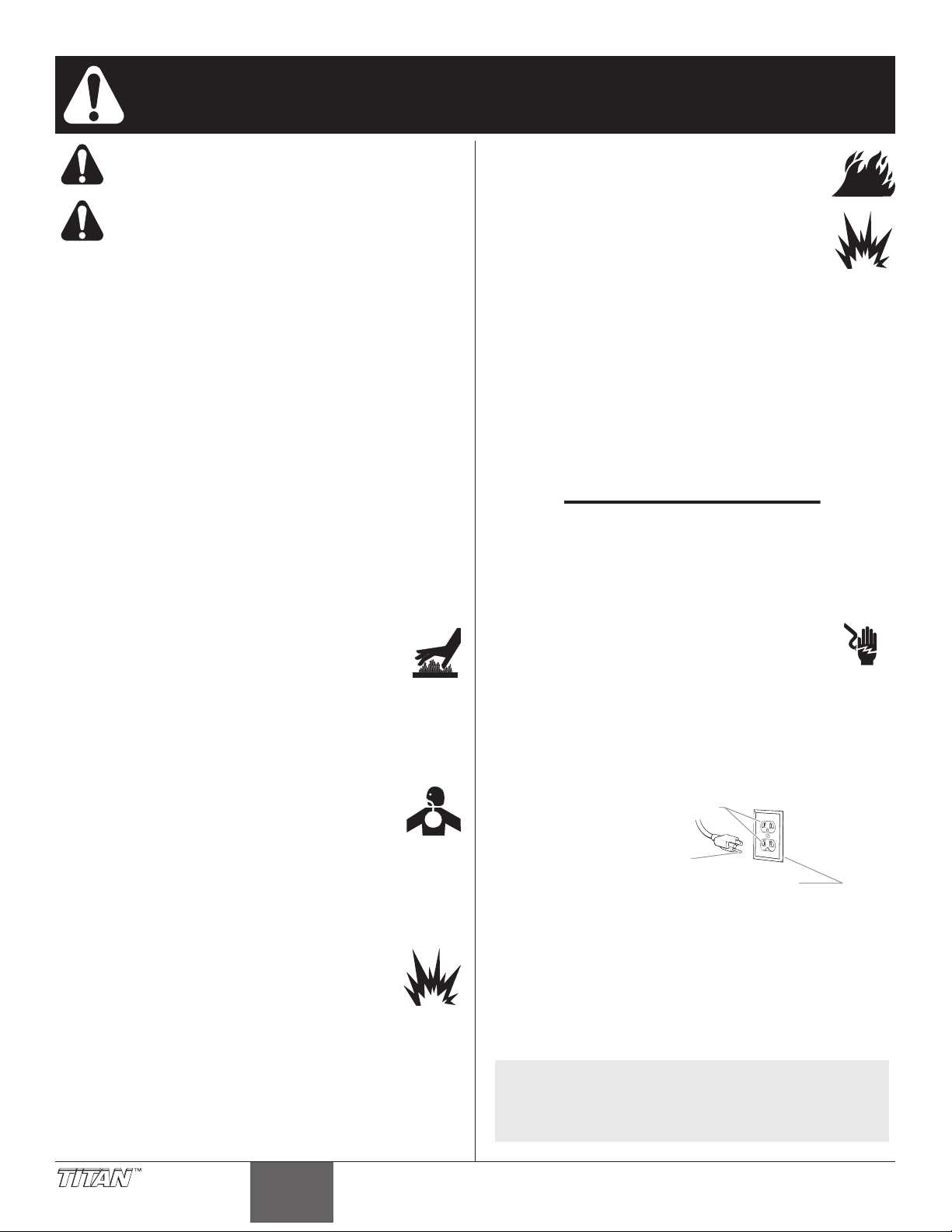
Grounded Outlet
Grounding Pin
Cover for grounded outlet box
operating the equipment. SAVE THESE INSTRUCTIONS.
This symbol indicates a hazardous situation, which, if not
not avoided could result in death or serious injury.
To reduce the risks of fire or explosion, electrical shock
and the injury to persons, read and understand all
instructions included in this manual. Be familiar with the
controls and proper usage of the equipment.
HAZARD: GENERAL
Can cause severe injury or property damage.
PREVENTION:
• Read all instructions and safety precautions before operating any
equipment.
• Comply with all appropriate local, state and national codes
governing ventilation, re prevention, and operation.
• The United States Government Safety Standards have been
adopted under the Occupational Safety and Health Act (OSHA).
These standards, particularly Part 1910 of the General Standards
and Part 1926 of the Construction Standard should be consulted.
• This equipment is designed to be used with authorized parts only.
When using this equipment with parts that do not comply with
the minimum specications and safety devices of the equipment
manufacturer, the user assumes all risks and liabilities.
• Check all hoses for cuts, leaks, abrasion or bulging of cover, as
well as damage or movement of couplings before each use. If any
of these conditions exist, replace the hose immediately. Never
repair a paint hose.
• Never aim the spray gun at any part of the body.
HAZARD: SKIN BURN INJURY
Heated parts can cause severe skin burn injury.
PREVENTION:
• Quick-disconnect ttings on the hose and the spray
gun become hot during use. Avoid skin contact with any quickdisconnect ttings when they are hot. Allow the quick disconnect
ttings to cool before disconnecting the spray gun from the hose
• The compressor becomes hot during use. Allow the compressor
to cool before touching it.
HAZARD: HAZARDOUS VAPORS
Paints, solvents, insecticides, and other materials can be
harmful if inhaled or come in contact with the body. Vapors can
cause severe nausea, fainting, or poisoning.
PREVENTION:
• Use a respirator or mask whenever there is a chance that vapors
may be inhaled. Read all instructions with the mask to insure that
it will provide the necessary protection against the inhalation of
harmful vapors.
• Avoid all ignition sources such as static electricity sparks, open
ames, pilot lights, hot objects, cigarettes, and sparks caused by
connecting and disconnecting power cords and operating light
switches.
• Keep the motor away from spray area to avoid solvent and paint
fumes. Motor contains arcing parts which emit sparks.
• Fire extinguishing equipment must be present and in working
order.
• The power cord must be connected to a grounded circuit.
• Follow the material and solvent manufacturer’s safety precautions
and warnings.
Grounding Instructions
This product must be grounded. In the event of an electrical short circuit,
grounding reduces the risk of electric shock by providing an escape
wire for the electric current. This product is equipped with a cord having
a grounding wire with an appropriate grounding plug. The plug must
be plugged into an outlet that is properly installed and grounded in
accordance with all local codes and ordinances.
WARNING - Improper installation of the grounding plug
can result in a risk of electric shock.
If repair or replacement of the cord or plug is necessary,
do not connect the green grounding wire to either at blade
terminal. The wire with insulation having a green outer
surface with or without yellow stripes is the grounding wire and must be
connected to the grounding pin.
Check with a qualied electrician or serviceman if the grounding
instructions are not completely understood, or if you are in doubt as
to whether the product is properly grounded. Do not modify the plug
provided. If the plug will not t the outlet, have the proper outlet installed
by a qualied electrician.
IMPORTANT: Use only a 3-wire extension cord that has a 3-blade
grounding plug and a 3-slot receptacle that will accept the plug on
the product. Make sure your extension cord is in good condition.
When using an extension cord, be sure to use one heavy enough
to carry the current your product will draw. An undersized cord
will cause a drop in line voltage resulting in loss of power and
overheating. A 12 gauge cord is recommended. If an extension
cord is to be used outdoors, it must be marked with the suffix
W-A after the cord type designation. For example, a designation
of SJTW-A would indicate that the cord would be appropriate for
outdoor use.
HAZARD: EXPLOSION
Compressed air has great force and may cause injury.
PREVENTION:
• The pressure pot assembly is protected from overpressurizing by a safety valve. Pull the ring on the safety valve
occasionally to make sure that the valve operates freely. The
valve must be replaced if it does not operate freely or if it does not
release air when the ring is pulled.
• Never modify the pressure pot or the compressor.
• Never connect other air tools to the compressor.
HAZARD: EXPLOSION OR FIRE
Solvent and paint fumes can explode or ignite. Property
damage and/or severe injury can occur.
PREVENTION:
• Exhaust and fresh air introduction must be provided
to keep the air within the spray area free from the
accumulation of ammable vapors.
• Keep the turbine at the maximum distance possible from the
spray area.
2 © Titan Tool. All rights reserved.
NOTE: More than 100 feet of extension cord is not
recommended. Use more paint hose, not more
extension cord. Shorter extension cords will assure
maximum electrical power for proper operation.
English
Page 3
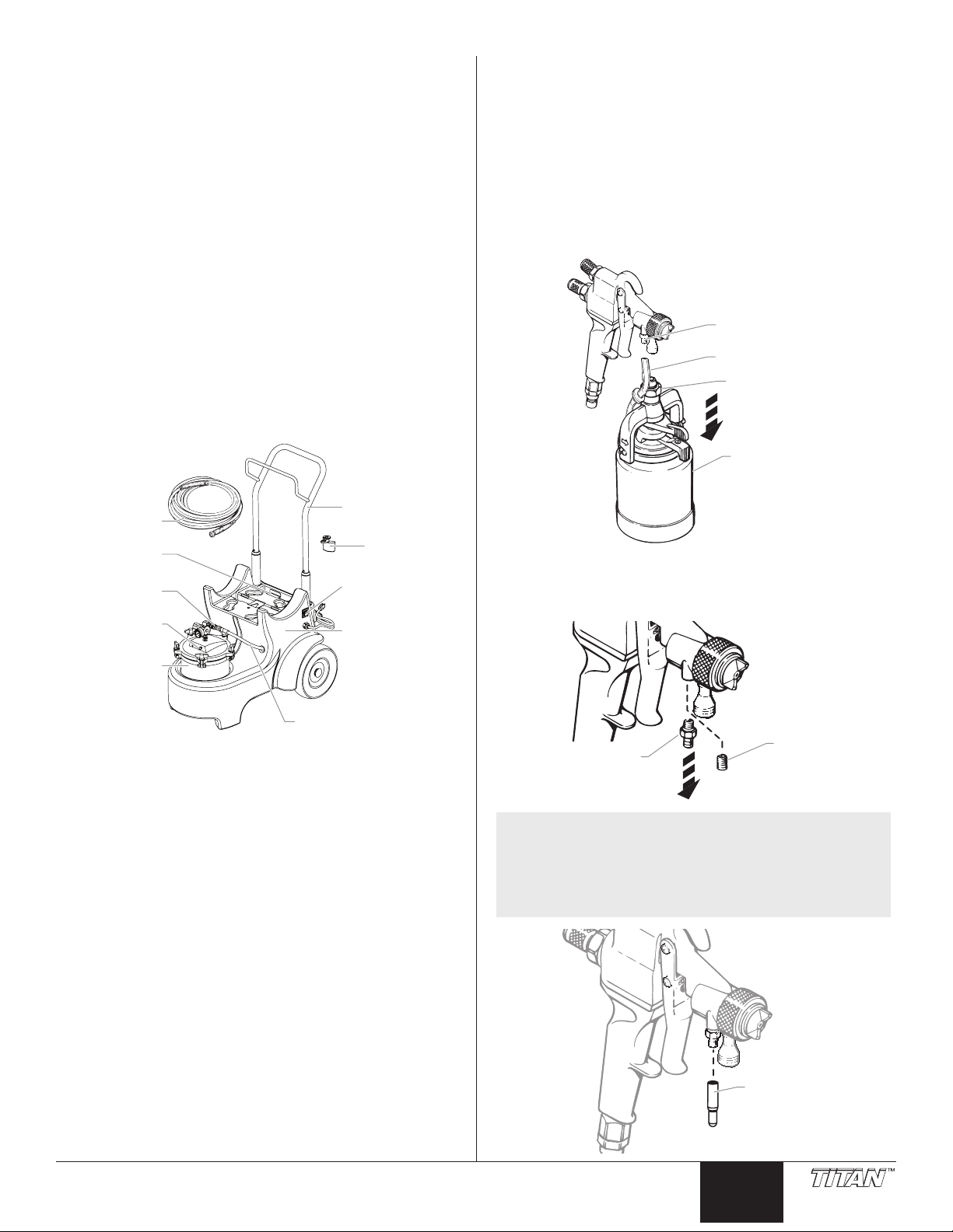
Table of Contents
Pressure Pot
Air Inlet
Latch Bracket
3/8” X 30 ft
Fluid hose
Pressure Pot
Fluid Outlet
Pressure Pot
Assembly
Pressure Pot Air Hose
Power Switch
Compressor
Assembly
(inside housing)
Cart
Turbine
Bracket
Air Tube
Retaining Nut
Cup Assembly
Air Tube Fitting
Set Screw
Air Tube Fitting
Air Tube Cap
Safety ......................................................................................... 2
Introduction ............................................................................... 3
Setup ..........................................................................................3
Converting the Gun to Pressure Feed................................. 3
Mounting the Turbine .......................................................... 4
Connecting the Power Cart ................................................. 4
Hose Congurations ............................................................ 4
Preparing to Spray .............................................................. 5
Cleanup .....................................................................................5
Troubleshooting ....................................................................... 6
Parts List ............................................................................20-21
Warranty .................................................................................. 24
Introduction
The HVLP power cart is designed for use with CAPspray spray
systems. The power cart adds tremendous versatility to an
already complete system. Components of the HVLP power
cart include a power switch, a cart, a pressure pot assembly, a
compressor assembly, a pressure pot inlet, a pressure pot hose,
a pressure pot outlet, a uid hose, and a turbine bracket.
Setup
Use the following procedures to set up your spray gun and HVLP
power cart.
Converting the Gun to Pressure Feed
Before using the HVLP power cart, it is necessary to convert your
spray gun from a cup gun to a pressure fed gun.
1. Loosen the retaining nut using a wrench and remove the
one quart cup assembly.
2. Pull the air tube off of the air tube tting on the spray gun.
© Titan Tool. All rights reserved. 3
3. Remove the air tube tting using a 1/4” wrench.
4. Thread the set screw into the air tube tting location and
tighten into place.
Optional (in place of steps 3 and 4): If desired, a
temporary cap (also included) can be used to close off
the air tube tting rather than performing steps 3 and 4
above. This is a convenient method of capping the air
tube tting if the operator will be frequently switching
back and forth between a 1-quart cup and a pressure pot.
English
Page 4
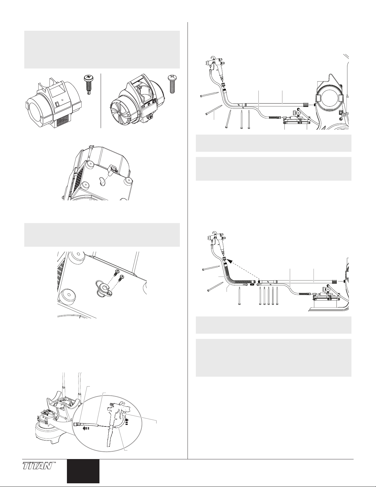
Mounting the Turbine
Pressure Pot Outlet
Fluid Hose
Fluid Hose
Spray Gun
Inlet
Air HoseFluid Hose
Straps
Air HoseFluid Hose
Fluid Whip
Hose
Air Whip
Hose
Straps
Move coupling
NOTE: If you are mounting an older CAPSpray turbine,
use the self-drilling screws shown on the left.
If you are mounting a newer Titan CAPSpray
turbine, use the thread-forming screws shown
on the right.
1. Insert plastic latch bracket into the bottom of the turbine as
shown.
2. Using a cordless drill with a Phillips driver, insert provided
screws into the casing using a low clutch setting. DO NOT
over-torque.
NOTE: If the drill does not have a clutch, drive the
screw with the drill until the threads start to
engage, and then tighten by hand.
Hose Congurations
Spraying without whip hoses
Follow the conguration below if you want to spray without the
uid and air whip accessories.
TIP: When strapping the hoses together, start at the
spray gun and work your way back.
NOTE: 30 ft uid hose - included with Power Cart.
30 ft air hose - included with turbine.
Hose straps - included with Power Cart
Spraying with whip hoses
Follow the conguration below if:
1. You already have the air whip hose and you purchased a
uid whip hose kit.
2. You have purchased both the uid whip hose kit and the
air hose whip kit.
3. Place the turbine onto the power cart. Push the latch
bracket in to secure the turbine.
Connecting the Power Cart
1. Thread the end of the uid hose onto the pressure pot
uid outlet and tighten.
2. Thread the other end of the material hose onto the spray
gun inlet and tighten.
4 © Titan Tool. All rights reserved.
English
TIP: When strapping the hoses together, start at the
spray gun and work your way back.
NOTE: 30 ft uid hose - included with Power Cart.
30 ft air hose - included with turbine.
5 ft air whip hose - included with the CS9900 and
CS9960
5 ft uid whip hose - sold separately.
Page 5
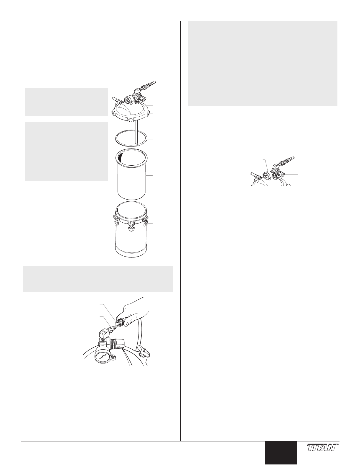
Preparing to Spray
Cover
Groove
Seal
Locking
Clamp
Pressure
Pot
Pot
Liner
Pressure Pot Air Inlet
Pressure Pot Air Hose
Pressure
Control
Knob
Pressure Control Gauge
IMPORTANT: Use a pot liner in the pressure pot when
spraying or cleaning with hot solvents such as lacquerbased paints, lacquer thinner, and M.E.K. The use of hot
solvents in the pressure pot without a pot liner may lift the
paint off the interior of the pressure pot and contaminate the
paint finish. Refer to the parts list in this manual for the pot
liner part number.
1. Fill the pressure pot with spray material.
TIP: On smaller jobs a onegallon container may be
placed inside the pressure pot
to aid in quicker cleanup.
NOTE: For best results,
always strain material prior to
spraying.
NOTE: When using the onegallon container, take care not
to tip the Power Cart back too
far in order to prevent material
from spilling out of the can.
NOTE: The compressor should run continuously (up to
2 minutes) upon initially charging the pressure
pot. As the compressor reaches the desired
pressure (set by the regulator), the compressor
will diminish its cycling rate. If the system
is left idle (i.e. no material being sprayed) for
several minutes, the compressor will cycle
periodically due to normal air losses. When the
system is idle the compressor may cycle up to
4 times per minute. If the compressor cycles
more frequently than this or does not stop, see
Troubleshooting section.
When material is being sprayed, the compressor
should normally cycle every 5-10 seconds.
5. Pull out the pressure control knob and turn it until the
pressure is set properly for the type of material you are
using.
For thin materials, set regulator to 8 PSI.
For thicker materials, set regulator to between 8 and
14 PSI.
2. Fasten the cover securely onto
the pressure pot by placing
the ve locking clamps into
the cover grooves and rotating
each clockwise until hand tight.
Be certain that the seal is in
place.
3. Connect the pressure pot air
hose to the pressure pot air
inlet.
NOTE: The hose features quick-disconnect ttings.
4. Plug in the power cords for both the Power Cart and the
To use, pull back on the spring-loaded collar
of each tting. Slide the hose tting over the
correct connection and release the collar.
turbine. Turn the cart power switch to the ON (I) position
to turn on the compressor.
6. Turn on the turbine.
7. Practice spraying on a piece of scrap wood or cardboard
until you are satised with the pressure, spray pattern, and
spray shape. The spray pattern adjustments and spray
shape selections are described in your gun manual.
Cleanup
1. Turn off the turbine.
2. Turn off the Power Cart.
3. Relieve the pressure from the pressure pot and remove
the pressure pot cover.
4. Remove excess material from the pot, wiping down the
inside of the pot and uid pick-up tube.
5. Place a container of the appropriate cleaning solvent into
the pressure pot to clean out the hose and gun.
6. Replace the cover, making sure the pickup tube is inside
the solvent container, and tighten the pot cover.
7. Turn on the Power Cart and adjust the pressure to 10 psi.
8. With the turbine off, depress the spray gun trigger while
pointing the gun into the material container. This will drain
the material into the container until all material has been
pushed through.
9. Continue running the solvent through the hose and gun
until they are completely clean.
© Titan Tool. All rights reserved. 5
English
Page 6

Troubleshooting
Problem
A. Compressor does not shut off
or runs more than 30% of the
time.
B. Compressor does not start
and there is no pressure in the
tank.
C. No material ow to spray gun.
Cause
1. Pressure pot lid not tight.
2. Lid gasket has material build-up, causing a
leak.
3. The compressor pressure switch is faulty.
4. Air ttings may be leaking.
1. No power to unit.
2. The regulator is set too low.
3. Compressor pressure switch is faulty.
4. Compressor motor is faulty.
5. Pressure gauge is faulty.
6. Regulator is faulty.
1. Regulator is set too low.
2. Hose or gun may be plugged.
Solution
1. Remove cover, reposition pot, replace cover and retighten clamps in a star pattern, increasing tightness
at each nut. Give one nal tightening to ensure
equal torque on each nut.
2. Inspect and clean the lid gasket, or replace with a
new gasket.
3. Replace the compressor pressure switch
(Replacement kit P/N 0524205 available by calling
technical service at 1-800-526-4826).
4. Bubble-check ttings to determine location.
Disassemble applicable joints. Add thread sealant.
Reassemble.
1. Check that the unit is plugged in and the outlet is
powered.
2. Turn clockwise to increase pressure.
3. Replace the compressor pressure switch
(Replacement kit P/N 0524205 available by calling
technical service at 1-800-526-4826).
4. Replace compressor (see parts list).
5. Replace pressure gauge (see parts list).
6. Replace regulator (see parts list).
1. Adjust regulator between 8-14 psi.
2. Inspect and clean.
D. Pressure pot relief valve
releases.
1. Regulator set too high.
2. Regulator is faulty.
3. Relief valve is faulty.
4. Pressure gauge is faulty.
1. Decrease pressure below 35 psi.
2. Replace regulator (see parts list).
3. Replace relief valve (see parts list).
4. Replace pressure gauge (see parts list).
6 © Titan Tool. All rights reserved.
English
Page 7
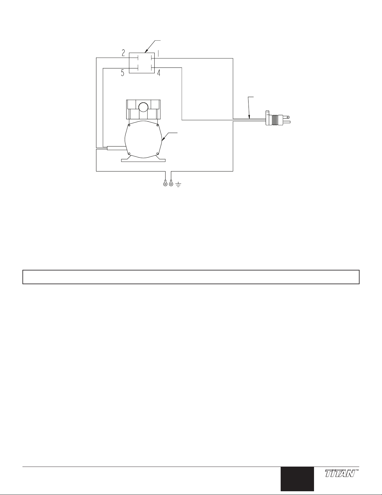
Electrical Schematic
ON/OFF switch
(P/N 9850936)
Compressor
(P/N 0524202)
Power cord
(P/N 0524313)
White
White
Black
Black
GreenGreen
Patents
These products are covered by one or more of the following U.S. patents:
5,550,336 5,556,255 5,639,222 5,702,131
5,772,711 5,655,714 5,558,492
Material Safety Data Sheets (MSDS) are available on Titan’s website or by calling Technical Service.
© Titan Tool. All rights reserved. 7
English
Page 8
Consignes de sécurite important · Lire toutes ces consignes avant
Prise trifilaire
Broche de mise à la terre
Plaque murale de la prise
d’utiliser l’appareil. GARDER CES CONSIGNES.
Indique une situation à risque, laquelle, si elle n’est pas
évitée, peut entraîner des blessures graves, voire la mort.
Pour réduire les risques d’incendie ou d’explosion, de
choc électrique et de blessure, vous devez lire et
comprendre les directives figurant dans ce manuel.
Familiarisez-vous avec les commandes et l’utilisation
adéquate de l’équipement.
DANGER : GÉNÉRAUX
Risques de dommages matériels et de blessures graves.
PRÉVENTION :
• Lire toutes les directives et mises en garde avant de faire
fonctionner l’équipement, quel qu’il soit.
• Se conformer à tous les codes locaux, provinciaux et nationaux
qui régissent la ventilation, la prévention des incendies et le
fonctionnement des dispositifs.
• Les normes de sécurité adoptées par le gouvernement américain
l’ont été en vertu de sa Occupational Safety and Health Act
(OSHA); ces normes, particulièrement les parties 1910 des
normes générales et 1926 des normes de construction, devraient
toujours être consultées.
• Cet équipement est conçu pour fonctionner avec les pièces
autorisées seulement. Si on l’utilise avec des pièces non
conformes aux spécications et exigences en matière de sécurité
du fabricant, on devra accepter les responsabilités et risques
inhérents.
• On doit s’assurer que les tuyaux soient exempts de coupures,
de fuites, d’abrasions ou de renements et que les raccords ne
soient ni endommagés ni mal assujettis avant chaque usage.
Le cas échéant, il faut remplacer le tuyau sur le champ, en ne
tentant jamais de le réparer.
• On ne doit jamais orienter le pistolet vers une partie du corps.
DANGER : DANGER DE BRÛLURE
Les pièces chauffées peuvent causer de graves brûlures
cutanées.
PRÉVENTION :
• Les raccords à dégagement rapide du tuyau exible et du pistolet
peuvent s’échauffer en cours d’utilisation; il faut alors éviter les
contacts cutanés, en attendant que les raccords refroidissent
avant de séparer le pistolet du tuyau.
• Le compresseur devient chaud à l’utilisation. Le laisser refroidir
avant d’y toucher.
DANGER : ÉMANATIONS DANGEREUSES
Les peintures, les solvants, les insecticides et autres
substances peuvent être dangereuses si inhalées, entraînant
de graves nausées, des pertes de connaissance ou une
intoxication.
PRÉVENTION :
• Utiliser un masque ou un respirateur en présence de risques
d’inhalation. Lire toutes les directives relatives au dispositif de
protection an d’en assurer l’efcacité dans l’usage auquel il est
destiné.
DANGER : EXPLOSION
L’air comprimé est très puissant et peut provoquer des
blessures.
PRÉVENTION :
• L’ensemble réservoir est protégé contre la surpression par une
soupape de sécurité. De temps en temps, tirer sur l’anneau de la
soupape de sécurité pour vérier qu’elle fonctionne normalement.
Remplacer la soupape si elle ne fonctionne pas bien ou si elle ne
laisse pas passer l’air quand on tire sur l’anneau.
• Ne jamais modier le réservoir sous pression ni le compresseur.
• Ne connecter aucun autre outil pneumatique au compresseur.
DANGER : D’EXPLOSION OU D’INCENDIE
Les émanations de solvants et de peintures peuvent exploser
ou s’enammer, entraînant des dommages matériels ou des
blessures graves.
PREVENTION :
• On doit assurer la ventilation et l’introduction d’air
neuf dans la zone de pulvérisation an d’éviter les
accumulations de vapeurs inammables.
• Placer la turbine le plus loin possible de la zone de pulvérisation.
• Il faut éviter les sources de combustion comme l’électricité
statique, les ammes nues, les veilleuses de bec de gaz, les
objets chauds, les cigarettes et les étincelles provoquées
par la connexion/déconnexion de cordon d’alimentation et la
commutation d’interrupteurs d’éclairage.
• Placer le moteur le plus loin possible de la zone de pulvérisation
pour l’éloigner des vapeurs de solvant et de peinture. Le moteur
contient des pièces qui peuvent émettre des étincelles.
• On doit avoir à portée de la main de l’équipement d’extinction en
bon état de marche.
• Le cordon d’alimentation doit être raccordé à un circuit mis à la
terre.
• S’assurer de suivre les directives en matière de sécurité et de
lire les mises en garde du fabricant des solvants et des produits
utilisés.
Instructions de mise à la terre
Cet appareil doit être mis à la terre. La mise à la terre réduit les risques
d’électrocution lors d’un court-circuit en permettant au courant de
s’écouler par le l de mise à la terre. Cet appareil est muni d’un cordon
électrique avec l de mise à la terre ainsi que d’une che de terre. La
che doit être branchée sur une prise installée correctement et mise à la
terre conformément à la réglementation et aux codes en vigueur.
MISE EN GARDE - Le fait de ne pas brancher correctement
la fiche trifilaire de l’appareil peut entraîner des risques de
choc électrique.
Si on doit réparer ou remplacer le cordon ou la che, ne pas raccorder
le l de terre à la borne des broches plates (lames) de cette dernière. Ce
l, normalement vert (avec ou sans rayures jaunes), doit être relié à la
broche de terre.
Consulter un technicien ou un électricien qualié à défaut de comprendre
l’ensemble des présentes directives ou en cas d’incertitude quant à la
mise à terre de l’appareil. Ne pas modier la che de l’appareil; si elle ne
s’adapte pas dans la prise voulue, faire remplacer cette dernière par un
électricien qualié.
IMPORTANT : Utiliser uniquement une rallonge à trois fils
munie d’une fiche de terre dans une prise secteur mise à la terre
correspondant au type de fiche de l’appareil. S’assurer que votre
rallonge est en bon état. Lorsque vous utilisez une rallonge,
assurez-vous qu’elle soit d’un calibre suffisant pour supporter
l’intensité du courant requise par l’appareil. Une rallonge trop
mince entraîne une chute de tension, une diminution de l’intensité
et une surchauffe. Une rallonge de calibre 12 est recommandée.
Si vous devez utiliser une rallonge à l’extérieur, celle-ci doit
comprendre la marque W-A après la désignation indiquant le type de
cordon. Par exemple, la désignation SJTW-A indique que le cordon
est conçu pour être utilisé à l’extérieur.
NOTA : On ne recommande pas l’utilisation de rallonges de
plus de 31 m (100 pi); il est préférable de rallonger
le tuyau à peinture que le cordon d’alimentation.
Les rallonges plus courtes assureront la puissance
électrique requise pour un fonctionnement adéquat.
8 © Titan Tool. Tous droits réservés.
Français
Page 9

Table des matières
Entrée d’air du
cylindre à pression
Loquet du support
Tuyau à peinture
de 3/8 po x 30 pi
Sortie de peinture
du cylindre à pression
Assemblage cylindre
à pression
Tuyau à air du
cylindre à pression
Interrupteur
Assemblage
compresseur
(à l’intérieur)
Chariot
Support à
turbine
Tuyau à air
Écrou de retenue
Godet
Raccord pour
tuyau à air
Raccord pour
tuyau à air
Vis de montage
Bouchon du tuyau à air
Sécurité .....................................................................................8
Introduction ............................................................................... 9
Préparation................................................................................ 9
Conversion du pistolet pour l’alimentation à pression ......... 9
Montage de la turbine........................................................ 10
Raccordement du Power Cart ........................................... 10
Congurations du tuyau .................................................... 10
Préparation préalable à la vaporisation ............................. 11
Nettoyage ................................................................................ 11
Dépannage .............................................................................. 12
Liste des pièces ................................................................. 20-21
Garantie ................................................................................... 22
Introduction
Le Power Cart HVLP est conçu pour les systèmes de
vaporisation CAPSpray. Le Power Cart ajoute beaucoup de
polyvalence à un système déjà complet. Le Power Cart HVLP
est équipé des composantes suivantes : interrupteur, chariot,
cylindre à pression, compresseur, entrée du cylindre à pression,
tuyau du cylindre à pression, sortie du cylindre à pression, tuyau
à peinture et support à turbine.
Préparation
Suivez les procédures suivantes pour préparer votre pistolet de
pulvérisation et Power Cart HVLP à l’emploi.
Conversion du pistolet pour l’alimentation à
pression
Avant d’utiliser le Power Cart HVLP, vous devez convertir votre
pistolet à godet en pistolet à alimentation à pression.
1. Desserrez l’écrou de retenue à l’aide d’une clé et retirez le
godet d’une pinte.
2. Détachez le tuyau d’air du raccord situé sur le pistolet.
© Titan Tool. Tous droits réservés. 9
3. Retirez le raccord du tuyau à air au moyen d’une clé de
1/4 po.
4. Vissez la vis de pression à la place du raccord du tuyau à
air et serrez.
FACULTATIF (à la place des étapes 3 et 4) : On peut
utiliser un bouchon temporaire (également compris) pour
boucher le raccord du tuyau à air, au lieu d’effectuer les
étapes 3 et 4 ci dessus, au besoin. Il s’agit d’une manière
pratique de bloquer le raccord du tuyau à air lorsque
l’opérateur alterne fréquemment entre le godet d’une
pinte et le cylindre à pression.
Français
Page 10

Montage de la turbine
Sortie de peinture
du cylindre à pression
Tuyau à peinture
Tuyau à peinture
Entrée du
pistolet de
pulvérisation
Tuyau à air Tuyau à fluid
Attaches
Tuyau à air Tuyau à fluide
Tuyau à
peinture
flexible
Tuyau à air
flexible
Attaches
Déplacer le couplage
NOTA : Si vous montez une vielle turbine de CAPSpray,
utiliser les vis auto-perceuse illustré sur la
gauche.
Si vous montez une nouveau turbine de Titan
CAPSpray, utiliser les vis autotaraudeuses
gurant sur la droite.
Congurations du tuyau
Vaporisation sans tuyaux exibles
Suivez la conguration ci-dessous si vous voulez vaporiser sans
les accessoires exibles à peinture et à air.
1. Insérez le support de blocage en plastique sous la turbine
tel qu’illustré.
2. À l’aide d’un tournevis électrique sans l avec embout
Phillips, insérez les vis fournies dans le boîtier en
choisissant un réglage de couple peu élevé. Ne serrez
PAS trop fort.
REMARQUE : Si le tournevis électrique ne possède pas
de réglages de couple, vissez jusqu’à ce que le let
s’engage, puis serrez à la main.
CONSEIL : Lorsque les tuyau cerclage, le départ à la
pistolets et de travailler en arrière.
REMARQUE :
Tuyau à uide de 30 pi – compris avec le Power Cart.
Tuyau à air de 30 pi – compris avec la turbine.
Attaches de tuyau – comprises avec le Power Cart.
Vaporisation avec tuyaux exibles
Respectez la conguration ci-dessous dans les cas suivants :
1. Vous possédez déjà le tuyau à air exible et vous avez
acheté un ensemble avec tuyau à peinture exible.
2. Vous avez acheté les ensembles avec tuyau à air exible
et tuyau à peinture exible.
3. Placez la turbine sur le chariot. Enfoncez le support de
blocage pour xer la turbine.
Raccordement du Power Cart
CONSEIL : Lorsque les tuyau cerclage, le départ à la
pistolets et de travailler en arrière.
1. Vissez l’une des extrémités du tuyau à peinture à la sortie
de peinture du cylindre à pression et serrez..
2. Vissez l’autre extrémité du tuyau au pistolet de
pulvérisation et serrez.
REMARQUE:
Tuyau à uide de 30 pi – compris avec le Power Cart.
Tuyau à air de 30 pi – compris avec la turbine.
Tuyau à air exible de 5 po - compris avec la modès
de CS9900 and CS9960.
Tuyau à peinture exible de 5 po - Vendu séparément.
10 © Titan Tool. Tous droits réservés.
Français
Page 11

Préparation préalable à la vaporisation
Couvercle
Rainure
Joint
d’étanchéité
Patte de
serrage
Cylindre
à pression
Doublure
du cylindre
Entrée d’air du cylindre
à pression
Tuyau à air du cylindre
à pression
Bouton de commande
de pression
Manomètre
IMPORTANT : Insérez une doublure dans le cylindre à
pression lorsque vous vaporisez ou nettoyez avec des
solvants chauds comme les peintures à base de laque, les
diluants à peinture-lacque et la méthylacétone. Utiliser des
solvants chauds dans le cylindre à pression sans y ajouter
une doublure risque de détacher la peinture qui recouvre
l’intérieur du cylindre et de contaminer le fini de la peinture.
Reportez-vous à la liste des pièces de ce manuel pour
connaître le numéro de la doublure pour cylindre.
1. Remplissez le cylindre à pression avec le matériau à
pulvériser.
CONSEIL : Pour les plus
petites tâches, vous pouvez
introduire un contenant
d’un gallon à l’intérieur du
cylindre à pression pour
faciliter le nettoyage.
REMARQUE : Pour de
meilleurs résultats, ltrez
toujours le matériau avant de
le vaporiser.
REMARQUE : Lorsque vous
vous servez d’un contenant
d’un gallon, assurez-vous de
ne pas trop incliner le chariot
vers l’arrière pour éviter que
le matériau se répande hors
du contenant.
2. Fixez solidement le
couvercle sur le cylindre à
pression en plaçant les cinq
pattes de serrage dans les
rainures du couvercle et
en les faisant tourner dans
le sens horaire jusqu’à ce
qu’elles soient bien serrées.
Assurez-vous que le joint
d’étanchéité est en place.
3. Raccordez le tuyau à air du cylindre à pression à l’entrée
d’air du cylindre à pression.
REMARQUE : Le tuyau est doté de raccords à
dégagement rapide. Pour dégager le tuyau, tirez sur
le collet à ressort de chaque raccord. Faites glisser le
raccord du tuyau sur le bon point de branchement, puis
relâchez le collet.
REMARQUE : Vous devez laisser fonctionner
le compresseur sans arrêt (jusqu’à 2 minutes)
pour permettre le chargement initial du cylindre à
pression. Lorsque le compresseur atteint sa pression
nominale (déterminée par le régulateur), sa cadence
de fonctionnement diminue. Lorsque le système est
laissé au repos (c’est à dire, aucune pulvérisation de
liquide) pendant plusieurs minutes, le compresseur se
met périodiquement en marche en raison des pertes
d’air normales. Il peut se mettre en marche jusqu’à
4 fois par minute lorsque le système est au repos. Si
le compresseur se met en marche plus fréquemment
ou s’il ne s’arrête jamais, voir la section consacrée au
dépannage.
Pendant la pulvérisation de liquide, le compresseur se
met normalement en marche toutes les 5 à 10 secondes.
5. Tirez sur le bouton de commande de pression et tournezle jusqu’à ce que la pression convienne au type de
matériau que vous utilisez.
Pour les matériaux légers, réglez le régulateur à 8 psi.
Pour les matériaux plus épais, réglez le régulateur
entre 8 et 14 psi.
6. Mettez la turbine en marche.
7. Essayez le jet sur un bout de bois ou de carton jusqu’à
ce que la pression, la forme et la largeur du jet soient
satisfaisantes. Consultez le manuel de votre pistolet
pour ajuster la forme du jet et pour connaître les choix
possibles.
Nettoyage
1. Éteignez la turbine.
2. Éteignez aussi le Power Cart.
3. Libérez la pression du cylindre à pression et retirez le
couvercle du cylindre.
4. Enlevez l’excédent de matériau en essuyant l’intérieur du
cylindre et le tuyau à peinture.
5. Placez un contenant renfermant le solvant approprié dans
le cylindre à pression pour nettoyer le tuyau et le pistolet.
6. Replacez le couvercle en vous assurant que le tube à
peinture est introduit dans le contenant de solvant, puis
serrez le couvercle.
7. Mettez le Power Cart sous tension et réglez la pression à
10 psi.
8. En laissant la turbine hors tension, pressez la détente du
pistolet en visant l’intérieur du contenant de matériau. De
cette façon, le matériau s’égouttera dans le contenant
jusqu’à évacuation complète.
9. Continuez à faire circuler le solvant dans le tuyau et le
pistolet jusqu’à ce qu’ils soient bien propres.
4. Branchez le cordon d’alimentation du chariot et de la
turbine sur une prise de courant. Tournez l’interrupteur
à la position ON (I) pour mettre le compresseur sous
tension.
© Titan Tool. Tous droits réservés. 11
Français
Page 12

Dépannage
Problème
A. Le compresseur ne s’arrête
pas ou il fonctionne plus de
30 % du temps.
B. Le compresseur refuse de
se mettre en marche et il n’y
a pas de pression dans le
réservoir.
Cause
1. Le couvercle du cylindre à pression n’est
pas bien fermé.
2. Il y a fuite car le joint d’étanchéité du
couvercle est couvert de peinture.
3. L’interrupteur à pression du compresseur
est défectueux.
4. Les raccords du tuyau à air pourraient
avoir une fuite.
1. Pas d’alimentation électrique.
2. Le réglage du régulateur est trop bas.
3. L’interrupteur à pression du compresseur
est défectueux.
4. Le moteur du compresseur est défectueux.
5. Le manomètre est défectueux.
6. Le régulateur est défectueux.
Solution
1. Retirez le couvercle, corrigez la position du cylindre,
replacez le couvercle et resserrez le collier de
serrage, qui a l’apparence d’une étoile, en serrant
chacun des écrous. Resserrez les une dernière fois
an de vous assurer que chaque écrou a reçu un
effort de serrage égal.
2. Inspectez et nettoyez le joint d’étanchéité du
couvercle.
3. Remplacez l’interrupteur à pression du compresseur
(appelez les services techniques au 1 800 5264826 pour demander la trousse de rechange P/N
0524205).
4. Faites une vérication antibulles an d’en déceler
l’origine. Démontez les joints en question. Ajoutez du
mastic pour tuyaux letés. Remontez les joints.
1. Vériez si l’appareil est branché correctement à
la prise électrique et si la prise est alimentée en
courant.
2. Tournez dans le sens horaire pour augmenter la
pression.
3. Remplacez l’interrupteur à pression du compresseur
(appelez les services techniques au 1 800 5264826 pour demander la trousse de rechange P/N
0524205).
4. Remplacez le compresseur (voir liste des pièces).
5. Remplacez le manomètre (voir liste des pièces).
6. Remplacez le régulateur (voir liste des pièces).
C. Le matériau ne coule pas vers
le pistolet.
D. Le détendeur de pression du
cylindre s’ouvre.
1. Le réglage du régulateur est trop bas.
2. Le tuyau ou le pistolet est peut-être
branché.
1. Le réglage du régulateur est trop élevé.
2. Le régulateur est défectueux.
3. Le détendeur de pression est défectueux.
4. Le manomètre est défectueux.
1. Réglez le régulateur entre 8 et 14 psi.
2. Inspectez et nettoyez.
1. Diminuez la pression sous 35 psi.
2. Remplacez le régulateur (voir liste des pièces).
3. Remplacez le détendeur de pression (voir liste des
pièces).
4. Remplacez le manomètre (voir liste des pièces).
12 © Titan Tool. Tous droits réservés.
Français
Page 13

Diagramme électrique
Commutateur
(Nº de pièce 9850936)
Compresseur
(Nº de pièce
0524202)
Cordon
(Nº de pièce 0524313)
Blanc
Blanc
Noir
Noir
Vert Vert
Brevets
Ces produits sont protégés par un ou plusieurs des brevets (U.S.A.) suivants :
5,550,336 5,556,255 5,639,222 5,702,131
5,772,711 5,655,714 5,558,492
Des ches techniques de sécurité des produits (FTSS) sont disponibles sur le site Internet de Titan ou par téléphone
en vous adressant au Service Client.
© Titan Tool. Tous droits réservés. 13
Français
Page 14

Información de seguridad importante · Lea toda la información de
Receptáculo conectado a tierra
Pata a tierra
Tapa de la caja de receptáculo conectada a tierra
Información de seguridad importante · Lea toda la información de
seguridad antes de operar el equipo. GUARDE ESTAS INSTRUCCIONES.
seguridad antes de operar el equipo. GUARDE ESTAS INSTRUCCIONES.
Indica una situación peligrosa que, de no evitarse, puede
causar la muerte o lesiones graves.
Para reducir los riesgos de incendios, explosiones,
descargas eléctricas o lesiones a las personas, lea y
entienda todas las instrucciones incluidas en este
manual. Familiarícese con los controles y el uso
adecuado del equipo.
PELIGRO: GENERAL
Puede causar daños en la propiedad o lesiones severas.
PREVENCIÓN:
• Lea todas las instrucciones y advertencias de seguridad antes de
hacer funcionar cualquier equipo.
• Cumpla con todos los códigos locales, estatales y nacionales de
ventilación, prevención de incendios y operación que rijan.
• Los Estándares de Seguridad del Gobierno de los Estados
Unidos se han adoptado bajo el Decreto de Seguridad y Salud
Ocupacionales (OSHA por sus siglas en inglés). Deben consultarse
estos estándares, particularmente la parte 1910 de los Estándares
Generales y la parte 1926 de los Estándares de la Construcción.
• Este equipo está diseñado para usarse solamente con piezas
autorizadas por el fabricante. Cuando se use este equipo con
piezas que no cumplan con las especicaciones mínimas ni con
las de los dispositivos de seguridad del fabricante de la bomba, el
usuario asumirá todos los riesgos y responsabilidades legales.
• Cada vez, antes de usarlo, revise todas las mangueras para ver que
no tengan cortadas, fugas, una cubierta desgastada por abrasión
o con abolladuras, así como uniones dañadas o que se hayan
movido. Si existiera cualquiera de estas condiciones, reemplace la
manguera inmediatamente. Nunca repare una manguera de pintura.
• Nunca apunte la pistola hacia alguna parte del cuerpo.
PELIGRO: QUEMADURA DE LA PIEL
Las piezas calientes pueden causar lesiones de quemadura de la
piel severas.
PREVENCIÓN:
• Las conexiones de desconexión rápida de la manguera y
la pistola de atomización se llegan a calentar mientras se
usan. Evite que la piel tenga contacto con las conexiones
de desconexión rápida cuando se calienten. Deje que las
conexiones de desconexión rápida se enfríen antes de
desconectar la pistola de atomización de la manguera.
• El compresor se calienta durante el uso. Permita que el
compresor se enfríe antes de tocarlo.
PELIGRO: VAPORES PELIGROSOS
Las pinturas, solventes, insecticidas y otros materiales
pueden ser peligrosos si se inhalan; pueden causar náuseas,
desmayos o envenenamientos severos.
PREVENCIÓN:
• Use un respirador o una mascarilla siempre que exista el riesgo de
poder inhalar los vapores. Lea las instrucciones de la mascarilla
para asegurarse de que proporcionará la protección necesaria
contra la inhalación de vapores dañinos.
PELIGRO: EXPLOSION
El aire comprimido tiene una gran fuerza y pudiera causar
lesiones.
PREVENCION:
• El ensamble del tanque de presión está protegido con una
válvula de seguridad en caso de una sobre presurización.
Ocasionalmente jale la argolla de la válvula de seguridad para
asegurarse que la válvula opere libremente. En caso de no
operar con libertad o si la válvula no libera aire cuando se jala la
argolla, debe cambiarse.
• Nunca modique el tanque de presión o el compresor.
• Nunca conecte otras herramientas de aire al compresor.
PELIGRO: INCENDIO O EXPLOSIÓN
Los vapores de los solventes y pinturas pueden explotar o
encenderse y causar con esto daños en la propiedad y/o
lesiones severas.
PREVENCIÓN:
• On doit assurer la ventilation et l’introduction d’air
neuf dans la zone de pulvérisation an d’éviter les
accumulations de vapeurs inammables.
• Mantenga la turbina a la máxima distancia posible del área de
pintado.
• Evite que haya cualquier fuente de ignición como la electricidad
estática, llamas abiertas, amas de pilotos, objetos calientes,
cigarros y chispas que provengan de conectar y desconectar cables
de energía e interruptores de luces que estén funcionando.
• Mantenga el motor alejado del área de pintado para evitar vapores
de solvente y pintura. El motor contiene partes que al arquear
producen chispas.
• Debe haber equipo para extinción de incendios que además
funcione bien.
• El cable de energía debe conectarse en un circuito que esté
conectado a tierra.
• Siga las medidas de precaución y advertencias de seguridad del
fabricante del material y del solvente.
Instrucciones para conectar a tierra
Este producto se debe conectar a tierra. En caso de que ocurra un
corto circuito, la conexión a tierra reduce el riesgo de choque eléctrico
al proporcionar un alambre de escape para la corriente eléctrica. Este
producto está equipado con un cable que tiene un alambre de conexión a
tierra con un enchufe de conexión a tierra apropiado. El enchufe se debe
enchufar en una toma de corriente que se haya instalado y conectado a
tierra debidamente, de acuerdo con todos los códigos y estatutos locales.
ADVERTENCIA - La instalación incorrecta del enchufe a
tierra puede ocasionar un riesgo de choque eléctrico.
Si es necesario reparar o cambiar el cable o el enchufe, no
conecte el cable verde a tierra a ninguno de las terminales de espiga
plana. El cable con aislamiento de color verde por fuera con o sin rayas
amarillas es el alambre a tierra y debe conectarse a la espiga a tierra.
Consulte a un electricista o técnico de servicio capacitado si las
instrucciones para la conexión a tierra no se entienden claramente o si
tiene dudas en cuanto a que el producto esté debidamente conectado a
tierra. No modifique el enchufe que se incluye. Si el enchufe no encaja
en el receptáculo, pida a un electricistas capacitado que instale un
receptáculo adecuado.
IMPORTANTE: Use solamente extensiones trifilares que tengan un
enchufe de conexión a tierra de 3 hojas y un receptáculo de triple
ranura que acepte el enchufe del producto. Asegúrese de que su
extensión esté en buenas condiciones. Cuando use una extensión,
asegúrese de usar una que sea lo suficientemente resistente como
para soportar la corriente que descargue su producto. Un cable de
un tamaño menor causará una caída de voltage en la línea que dará
como resultado una pérdida de energía y un sobrecalenta|ôento. Se
recomienda usar un cable de calibre 12. Si se utiliza un cable de
extensión en el exterior, tiene que estar marcado con el sufijo W-A
después de la designación del tipo de cable. Por ejemplo, SJTW-A
para indicar que el cable es apropiado para uso en exteriores.
NOTA: No se recomienda usar una extensión de más de 100
pies. Use una longitud mayor de manguera de pintura,
no una extensión más larga. Una extensión más corta
asegurará que haya la energía eléctrica máxima para
tener un funcionamiento apropiado.
14 © Titan Tool. Todos los derechos reservados.
Español
Page 15

Tabla de Contenido
Entrada de aire del
tanque de presión
Lengüeta soporte
Manguera para
fluidos de 3/8” x
30 pies
Salida de fluido del
tanque de presión
Ensamblaje del
tanque de presión
Manguera de aire
del tanque de presión
Interruptor
de energía
Ensamblaje
de compresor
(dentro de la
caja)
Manija
Soporte
de turbina
Tuyau à air
Écrou de retenue
Godet
Raccord pour
tuyau à air
Adaptador del
tubo de aire
Tornillo de ajuste
Ta pa del tubo de aire
Seguridad ................................................................................ 14
Introducción ............................................................................ 15
Conguración ......................................................................... 15
Cómo Convertir la Pistola a una Alimentada a Presión .... 15
Cómo Montar la Turbina.................................................... 16
Cómo Conectar el Power Cart .......................................... 16
Conguraciones de la Manguera ...................................... 16
Preparación para Rociar ................................................... 17
Limpieza .................................................................................. 17
Solución de Problemas .......................................................... 18
Lista de Piezas ................................................................... 20-21
Garantía ................................................................................... 23
Introducción
El Power Cart HVLP (de Alto Volumen y Baja Presión) está
diseñado para su uso con sistemas de rociadores CAPSpray. El
Power Cart le brinda gran versatilidad a un sistema ya completo.
Los componentes del Power Cart HVLP incluyen un interruptor
de energía, una manija, un ensamblaje de tanque de presión, un
ensamblaje de compresor, una entrada de tanque de presión,
una manguera de tanque de presión, una salida de tanque de
presión, una manguera para uidos y un soporte de turbina.
Conguración
Utilice los siguientes procedimientos para congurar su pistola
rociadora y Power Cart HVLP.
Cómo Convertir la Pistola a una Alimentada a
Presión
Antes de utilizar el Power Cart HVLP, es necesario convertir su
pistola rociadora de una pistola de copa a una pistola alimentada
a presión.
1. Aoje la tuerca de sujeción con una llave y quite el
ensamblaje de compartimiento de un cuarto.
2. Tire del tubo de aire hacia afuera del acoplador del tubo
de aire que se encuentra en la pistola rociadora.
© Titan Tool. Todos los derechos reservados. 15
3. Quite el acoplador de tubo de aire por medio de una llave
de 1/4”.
4. Enrosque el tornillo jado en el lugar del acoplador de
tubo de aire y ajústelo en su lugar.
OPCIONAL (válido para pasos 3 y 4): Si lo desea, se
puede utilizar una tapa temporal (también incluida) para
cerrar el acoplamiento del tubo de aire en vez de llevar
a cabo los pasos 3 y 4 arriba mencionados. Este es un
método conveniente de tapar el acoplamiento del tubo de
aire si el operador alternará de manera frecuente entre
una taza de 1 cuarto y un tanque de presión.
Español
Page 16

Cómo montar la turbina
Salida del tanque de presión
Manguera para fluidos
Manguera para fluidos
Entrada de
la pistola
rociadora
Manguera
para fluidos
Manguera
para aire
Correas
Manguera
flexible
para fluidos
Manguera
flexible
para aire
Mover el acoplamiento
Manguera
para fluidos
Manguera
para aire
Correas
NOTA: Si va a montar una turbina de CAPSpray
mayores, utilice los tornillos autotaladrantes
muestra a la izquierda.
Si va a montar una nueva turbina de Titan
CAPSpray, utilice los tornillos autoroscantes
muestra a la derecha.
Conguraciones de la Manguera
Cómo rociar sin mangueras exibles
Siga la conguración a continuación si desea rociar sin los
accesorios exibles de uidos y aire.
1. Inserte un soporte de seguridad plástico en el fondo de la
turbina como se muestra.
2. Por medio de un taladro inalámbrico con punta de
destornillador Phillips, inserte los tornillos que se incluyen
en la cubierta utilizando un ajuste de embrague bajo. NO
ajuste demasiado.
NOTA: Si el destornillador no posee embrague, atornille
con el taladro hasta que las roscas comiencen a
ajustarse, y luego ajuste a mano.
CONSEJO: Cuando el tirante del mangueras, comenzar
en la pistola y el trabajo atrás.
NOTA: Manguera para uidos de 30 pies - incluida con
el Power Cart.
Manguera para aire de 30 pies - incluida con la
turbina.
Correas para manguera - incluidas con el Power
Cart.
Cómo rociar con mangueras exibles
Siga la conguración a continuación si usted:
1. Ya tiene la manguera exible para aire y adquirió un juego
de manguera exible para uidos.
2. Ya tiene ambos, el juego de manguera exible para
uidos y el juego exible de manguera para aire.
3. Coloque la turbina sobre el power cart. Empuje el soporte
de seguridad hacia adentro para asegurar la turbina.
Cómo Conectar el Power Cart
1. Enrosque el extremo de la manguera para uidos en la
CONSEJO: Cuando el tirante del mangueras, comenzar
en la pistola y el trabajo atrás.
salida de uidos del tanque de presión y ajuste.
2. Enrosque el otro extremo de la manguera para material
en la entrada de la pistola rociadora y ajuste.
NOTA: Manguera para uidos de 30 pies - incluida con
el Power Cart.
Manguera para aire de 30 pies - incluida con la
turbina.
Manguera exible para aire de 5 pies - incluida
con modelos de CS9900 y CS9960,
Manguera exible para uidos de 5 pies - se
16 © Titan Tool. Todos los derechos reservados.
Español
vende por separado
Page 17

Preparación para Rociar
Cubierta
Ranura
Sello
Abrazadera
de seguridad
Ta nque
de presión
Funda para
tanques
Entrada de aire del
tanque de presión
Manguera de aire del
tanque de presión
Perilla de control
de presión
Medidor de control
de presión
IMPORTANTE: Utilice una funda para tanques en el tanque
de presión cuando rocíe o limpie con solventes calientes
tales como pinturas a base de laca, disolvente de laca y
MEK (Metil Etil Cetona). El uso de solventes calientes en
el tanque de presión sin una funda para tanques puede
despegar la pintura del interior del tanque de presión y
contaminar el acabado de pintura. Consulte la lista de
piezas en este manual para el número correspondiente a la
funda para tanques.
1. Llene el tanque de presión con el material a rociar.
CONSEJO: En trabajos más
pequeños, puede colocarse
un contenedor de un galón
dentro del tanque de presión
para ayudar a limpiar más
rápidamente.
NOTA: Para obtener mejores
resultados, cuele siempre el
material antes de rociar.
NOTA: Al utilizar el
contenedor de un galón,
asegúrese de no inclinar
demasiado hacia atrás el
Power Cart para evitar que el
material se derrame.
NOTA: El compresor debe funcionar en forma continua
(hasta 2 minutos) para cargar inicialmente el
tanque de presión. A medida que el compresor
alcance la presión que desee (jada por
el regulador), el compresor disminuirá su
velocidad de ciclo. Si se deja inactivo el sistema
(es decir, no se pulveriza material) durante
varios minutos, el compresor realizará un ciclo
de manera periódica debido a las pérdidas de
aire normales. Cuando el sistema esté inactivo,
el compresor puede realizar un ciclo hasta 4
veces por minuto. Si el compresor realiza un
ciclo de manera más frecuente que ésta o no
se detiene, consulte la sección Solución de
problemas.
Cuando se pulveriza material, normalmente el
compresor debiera realizar un ciclo cada 5 a 10
segundos.
5. Tire hacia afuera la perilla de control de presión y gírela
hasta ajustar la presión en forma adecuada al material
que está utilizando.
Para materiales delgados, ajuste el regulador a 8 PSI.
Para materiales más gruesos, ajuste el regulador
entre 8 y 14 PSI.
2. Ajuste bien la cubierta
al tanque de presión
colocando las cinco
abrazaderas de seguridad
en las ranuras de la
cubierta y rotando cada
una de ellas en el sentido
de las manecillas del reloj
hasta que estén ajustadas.
Asegúrese de que el sello
esté en su lugar.
3. Conecte la manguera de aire del tanque de presión a la
entrada de aire del tanque de presión.
NOTA: La manguera posee acopladores de fácil
4. Enchufe los cables de alimentación del Power Cart y de
la turbina. Lleve el interruptor del cart power a la posición
de ON (I) para encender el compresor.
© Titan Tool. Todos los derechos reservados. 17
conexión. Para utilizarlos, tire hacia atrás
el collar accionado por resortes de cada
acoplador. Deslice el acoplador de manguera
sobre la conexión correcta y suelte el collar.
6. Encienda la turbina.
7. Practique rociando un trozo de madera desechable
o cartón hasta que esté satisfecho con la presión, la
modalidad de rociado y la forma de rociado. Los ajustes
para la modalidad de rociado y las selecciones de forma
de rociado están descriptos en el manual de su pistola.
Limpieza
1. Apague la turbina.
2. Apague el Power Cart.
3. Libere la presión del tanque de presión y quite la cubierta
del tanque de presión.
4. Quite el exceso de material del tanque, limpiando el
interior del tanque y el tubo receptor de uidos.
5. Coloque un contenedor del solvente de limpieza
apropiado dentro del tanque de presión para limpiar la
manguera y la pistola.
6. Reemplace la cubierta, asegúrese de que el tubo receptor
esté dentro del contenedor de solvente, y ajuste la
cubierta del tanque.
7. Encienda el Power Cart y ajuste la presión a 10 psi.
8. Con la turbina apagada, quite presión en el gatillo de la
pistola rociadora mientras apunta dentro del contenedor
del material. Esto permitirá vaciar el material dentro
del contenedor hasta que todo el material haya sido
transferido.
9. Siga haciendo correr el solvente a través de la manguera
y la pistola hasta que éstas estén completamente limpias.
Español
Page 18

Solución de problemas
Problema
A. El compresor no se apaga
o funciona un 30% más de
tiempo.
B. El compresor no arranca y no
hay presión en el tanque.
Causa
1. La tapa del tanque de presión no está
ajustada.
2. La junta de la tapa tiene material
acumulado y, por lo tanto, causa una
ltración.
3. El interruptor de presión del compresor
está defectuoso.
4. Los acopladores de aire pueden tener
fugas.
1. La unidad no recibe suministro eléctrico.
2. El regulador está ajustado demasiado
bajo.
3. El interruptor de presión del compresor
está defectuoso.
4. El motor del compresor está defectuoso.
5. El medidor de presión está defectuoso.
6. El regulador está defectuoso.
Solución
1. Retire la cubierta, vuelva a colocar el tanque,
vuelva a colocar la cubierta y vuelva a apretar las
abrazaderas en estrella, apriete cada vez más cada
tuerca. Apriete una última vez para asegurar una
torsión igual en cada tuerca.
2. Revise y limpie la junta de la tapa.
3. Reemplace el interruptor de presión del compresor
(Juego de repuesto P/N 0524205 disponible
llamando al servicio técnico al 1-800-526-4826).
4. Verique que los acopladores no tengan burbujas de
aire y determine en donde se encuentran si las hay.
Desarme las juntas pertinentes. Añada sellador para
rosca. Vuelva a ensamblar todo.
1. Controle que la unidad esté enchufada y que el
enchufe tenga corriente.
2. Gire en el sentido de las manecillas del reloj para
aumentar la presión.
3. Reemplace el interruptor de presión del compresor
(Juego de repuesto P/N 0524205 disponible
llamando al servicio técnico al 1-800-526-4826).
4. Reemplace el compresor (ver lista de piezas).
5. Reemplace el medidor de presión (ver lista de
piezas).
6. Reemplace el regulador (ver lista de piezas).
C. El material no circula por la
pistola rociadora.
D. La válvula de seguridad del
tanque de presión se suelta.
1. El regulador está ajustado demasiado
bajo.
2. La manguera o la pistola pueden estar
enchufadas.
1. El regulador está ajustado demasiado alto.
2. El regulador está defectuoso.
3. La válvula de seguridad está defectuosa.
4. El medidor de presión está defectuoso.
1. Ajuste el regulador entre 8 y 14 psi.
2. Revise y limpie.
1. Disminuya la presión a menos de 35 psi.
2. Reemplace el regulador (ver lista de piezas).
3. Reemplace la válvula de seguridad (ver lista de
piezas).
4. Reemplace el medidor de presión (ver lista de
piezas).
18 © Titan Tool. Todos los derechos reservados.
Español
Español
Page 19

Diagrama eléctrico
Interruptor
(No. de pieza 9850936)
Compresor
(No. de pieza
0524202)
Cordón
(No. de pieza 0524313)
Blanco
Blanco
Negro
Negro
VerdeVerde
Patentes
Estos productos están protegidos por una de las siguientes patentes (U.S.A.):
5,550,336 5,556,255 5,639,222 5,702,131
5,772,711 5,655,714 5,558,492
Las Hojas de Datos de Seguridad (Material Safety Data Sheets - MSDS) se encuentran disponibles en el sitio web de Titan o
llamando al Servicio al Cliente.
© Titan Tool. Todos los derechos reservados. 19
Español
Page 20

Parts List • Liste de pièces • Lista de piezas
1
24
2
3
4
8
9
10
18
22
23
20
26
27
28
29
30
31
25
32
33
34
35
37
38
39 40
36
21
19
5
6
7
11
12
13
14
16
17
15
20 © Titan Tool. All rights reserved.
English
EspañolFrançais
Page 21

English
Item Part # Description Quantity
1 0275697 Fitting, 90° elbow, brass ..................................... 2
2 0275696 Fitting, 1/4” male, air nipple ................................ 1
3 0275640 Coupler, air ......................................................... 1
4 0524316 Compressor hose ............................................... 1
5 0276538 Gauge, Air........................................................... 1
6 0524442 Regulator ............................................................ 1
7 05045 Fitting, 1/4” x 1/4” ................................................ 1
8 0275717 Relief valve ......................................................... 1
9 0277348 Hose, uid 3/8” x 30 ft ......................................... 1
10 0275698 Fitting, uid ......................................................... 1
11* ------- Pot lid .................................................................. 1
12* 0508943 Gasket, pot ......................................................... 1
13* 0279924 Tube, pick up ...................................................... 1
14* 0275702 Pot liner .............................................................. 1
15 0524322 Screw, Truss #10-32 X 1/2” ................................ 1
16* ------- Pot bottom .......................................................... 1
0279285 Galvanized pot bottom (accessory)
17 0524365 Edge protector .................................................... 1
18 9850936 Power switch assembly ...................................... 1
19 765-063 Strain relief.......................................................... 1
20 0524313 Power cord set .................................................... 1
21 0278373 Wheel.................................................................. 2
22 0294534 Spacer, wheel ..................................................... 4
23 9890104 Cap, hub ............................................................. 2
24 0524309 Handle, cart ........................................................ 1
Français
Article Nº de pièce Description Quantité
1 0275697 Raccord, coude laiton à 90° ............................... 2
2 0275696 Raccord, raccord d’air mâle
de 1/4” pouce ...................................................... 1
3 0275640 Coupleur, d’air .................................................... 1
4 0524316 Tuyau de compresseur ....................................... 1
5 0276538 Manomètre.......................................................... 1
6 0524442 Détendeur ........................................................... 1
7 05045 Raccord, 1/4” x 1/4” ............................................ 1
8 0275717 Soupape de surpression ..................................... 1
9 0277348 Tuyau, uide 3/8” x 30 ft ..................................... 1
10 0275698 Raccord, uide .................................................... 1
11* ------- Couvercle............................................................ 1
12* 0508943 Joint, réservoir .................................................... 1
13* 0279924 Tuyau xateur ..................................................... 1
14* 0275702 Doublure de protection ....................................... 1
15 5024322 Vis, treillis, #10-32 x 1/2” .................................... 1
16* ------- Réservoir, fond ................................................... 1
0279285 Fond de réservoir galvanisé (accessoire)
17 0524365 Coussinet de protection ...................................... 1
18 9850936 Ensemble de interrupteur ................................... 1
19 765-063 Renfort ................................................................ 1
20 0524313 Jeu de câble d’alimentation ................................ 1
21 0278373 Roue ................................................................... 2
22 0294534 Entretoise, roue .................................................. 4
23 9890104 Chapeau du moyeu ............................................ 2
24 0524309 Poignée du chariot .............................................. 1
Item Part # Description Quantity
25 590-508 Roll pin, 5/16” x 1 1/8”......................................... 2
26 9841504 Button, snap........................................................ 2
27 590-504 Sleeve, handle .................................................... 2
28 590-506 Washer, at......................................................... 2
29 0524320 Screw, Pan, #10, self-drilling .............................. 2
30 0524319 Turbine latch plug ............................................... 1
31 856-002 Washer lock #10 ................................................. 4
32 856-921 Screw, pan #10-32 x 1/4”.................................... 4
33 0524308 Bracket, latch ...................................................... 1
34 0524202 Compressor assembly ........................................ 1
35 0524321 Fitting, 90º, 1/8” x 1/4” ........................................ 1
36 0524318 Nut, #10-32 ......................................................... 4
37 9802526 Screw, 1/4”-20 x 1/2” .......................................... 4
38 9802252 Screw, #10-32 x 3/4”........................................... 4
39 9805229 Screw, 1/4-20 x 2”............................................... 4
40 9820206 Washer, at......................................................... 9
Accessories
0508183 Spray hose, 1/4” x 30’
*0275692 Pressure pot assy (includes items 8, 10-13, 16)
0295272 Pot liners, 12 pack
0524206 Fluid whip hose kit, 1/4”
0524205 Pressure Switch Replacement kit
0295727 Hose strap
0524212 Pressure cap (3)
Article Nº de pièce Description Quantité
25 590-508 Goupille rouleau, 5-16” x 1 1/8” .......................... 2
26 9841504 Bouton d’enclenchement .................................... 2
27 590-504 Manche de poignée ............................................ 2
28 590-506 Rondelle plate ..................................................... 2
29 0524320 Vis, pan, #10, L’autonomie de forage ................. 2
30 0524319 Support de la turbine .......................................... 1
31 856-002 Rondelle de sécurité, #10 ................................... 4
32 856-921 Vis, pan #10-32 x 1/4”......................................... 4
33 0524308 Loquet du support ............................................... 1
34 0524202 Ensemble compresseur ...................................... 1
35 0524321 Raccord, coude laiton à 90°, 1/8” x 1/4” ............. 1
36 0524318 écrou, #10-32...................................................... 4
37 9802526 Vis, 1/4”-20 x 1/2” ............................................... 4
38 9802252 Vis, #10-32 x 3/4”................................................ 4
39 9805229 Vis, 1/4-20 x 2”.................................................... 4
40 9820206 Rondelle, Plate ................................................... 9
Accessoires
0508183 Tuyau de pulvériser, 1/4” x 30 po
*0275692 Ensemble de réservoir sous pression
(comprend les éléments 8, 10-13, 16)
0295272 Doublures, paquet de 12
0524206 Ensemble avec tuyau
à peinture exible, 1/4 po
0524205 Trousse de rechange de l’interrupteur à pression
0295727 Attache à tuyau
0524212 Couvercle étanche à la pression (3)
Español
Artículo Pieza # Descripción Cantidad
1 0275697 Conector, 90° Codo, Latón ................................. 2
2 0275696 Conector, 1/4” Macho, Niple de Aire................... 1
3 0275640 Cople .................................................................. 1
4 0524316 Manguera del compresor .................................... 1
5 0276538 Medidor, Aire ...................................................... 1
6 0524442 Regulador ........................................................... 1
7 05045 Conector, 1/4” x 1/4” ........................................... 1
8 0275717 Aliviar la válvula .................................................. 1
9 0277348 Manguera, Fluido 3/8” x 30 ft .............................. 1
10 0275698 Conector, Fluido ................................................. 1
11* ------- Tapa.................................................................... 1
12* 0508943 Empaque, Tanque .............................................. 1
13* 0279924 Tubo, Pick Up ..................................................... 1
14* 0275702 Forro del Tanque ............................................... 1
15 5024322 Tornillo ................................................................ 1
16* ------- Fondo del Tanque............................................... 1
0279285 Fondo galvinizado de tanque (accesorio)
17 0524365 Protector de borde .............................................. 1
18 9850936 Ensamblaje de interruptor................................... 1
19 765-063 Aliviador de Tensión ........................................... 1
20 0508337 Conjunto de cable de energía............................. 1
21 0278373 Rueda ................................................................. 2
22 0294534 Espaciador, Rueda ............................................. 4
23 9890104 Tapa, Eje ............................................................ 2
24 0524309 Mango de Carrito ................................................ 1
© Titan Tool. All rights reserved. 21
Artículo Pieza # Descripción Cantidad
25 590-508 Pasador de rollo, 5-16” x 1 1/8” .......................... 2
26 9841504 Botón, a presion.................................................. 2
27 590-504 Manga de carrito ................................................. 2
28 590-506 Rondana, plana .................................................. 2
29 0524320 Tornillo, pan #10, La libre perforación ................ 2
30 0524319 Turbina de soporte.............................................. 1
31 856-002 Rondana de seguridad, #10 ............................... 4
32 856-921 Tornillo, pan #10-32 x 1/4” .................................. 4
33 0524308 Lengüeta soporte ................................................ 1
34 0524202 Ensamble del Compresor ................................... 1
35 0524321 Conector, 90° Codo, 1/8” x 1/4” .......................... 1
36 0524318 Tuerca,#10-32 .................................................... 4
37 9802526 Tornillo,1/4”-20 x 1/2”.......................................... 4
38 9820252 Tornillo, #10-32 x 3/4” ........................................ 4
39 9805229 Tornillo, 1/4-20 x 2” ............................................. 4
40 9820206 Rondelle, piso ..................................................... 9
Accesorios
0508183 Manguera de rociadora, 1/4” x 30’
*0275692 Ensamblaje del tanque de presión
(incluye artículos del 8, 10-13, 16)
0295272 Fundas para tanques, paquete de 12
0524206 Juego de manguera exible
para uidos de 1/4”
0524205 Juego de Repuesto de Interruptor de Presión
0295727 Correa para manguera
0524212 Tapa de presión (3)
Español Français
English
Page 22

Garantie Limitée
Titan Tools, inc. (« Titan ») garantit qu’au moment de la livraison à l’acheteur original (« Utilisateur »), l’appareil couvert par la
présente garantie sera exempt de défauts de matériaux et de fabrication. Avec l’exception de spécial, limité, ou garantie allongée
publiée par de Titan, les responsabilités de Titan en vertu de cette garantie se limitent au remplacement ou à la réparation sans frais
des pièces dont on aura, à la satisfaction raisonnable de Titan, démontré la défectuosité dans un délai de douze (12) mois après la
date d’achat par l’Utilisateur. Cette garantie ne s’applique que si l’appareil a été installé et utilisé conformément aux recommandations
et directives de Titan.
Cette garantie ne s’applique pas dans les cas d’endommagement ou d’usure engendrés par de l’abrasion, de la corrosion, un mauvais
usage, de la négligence, un accident, une installation incorrecte, un remplacement par des composants non fournis par Titan ou toute
intervention non autorisée apte à nuire au fonctionnement normal de l’appareil.
Les pièces défectueuses doivent être envoyées à un centre de service/vente Titan autorisé; les frais de transport, incluant le retour
à l’usine, le cas échéant, doivent être défrayés à l’avance par l’Utilisateur. Une fois remplacées ou réparées, les pièces seront
renvoyées à ce dernier par transport prépayé.
AUCUNE AUTRE GARANTIE EXPLICITE N’EST DONNÉE. PAR LES PRÉSENTES, TITAN SE DÉGAGE DE TOUTE
AUTRE GARANTIE IMPLICITE, INCLUANT, SANS TOUTEFOIS S’Y LIMITER, LES GARANTIES DE COMMERCIABILITÉ ET
D’ADAPTATION À UN USAGE PARTICULIER, DANS LES LIMITES PERMISES PAR LA LOI. LA DURÉE DES GARANTIES
IMPLICITES NE POUVANT ÊTRE DÉCLINÉES SE LIMITE À LA PÉRIODE INDIQUÉE DANS LA GARANTIE EXPLICITE. LES
RESPONSABILITÉS DE TITAN NE SAURAIENT EN AUCUN CAS SE CHIFFRER À UN MONTANT SUPÉRIEUR À CELUI DU
PRIX D’ACHAT, ET CELLES RELATIVES AUX DOMMAGES CONSÉCUTIFS, ACCESSOIRES OU PARTICULIERS EN VERTU DE
TOUTE GARANTIE SONT ÉGALEMENT DÉCLINÉES, DANS LES LIMITES PERMISES PAR LA LOI.
TITAN NE DONNE AUCUNE AUTRE GARANTIE EXPLICITE ET DÉCLINE TOUTE GARANTIE IMPLICITE DE COMMERCIABILITÉ
ET D’ADAPTATION À UN USAGE PARTICULIER RELATIVEMENT AUX ACCESSOIRES, À L’ÉQUIPEMENT, AUX MATÉRIAUX OU
AUX COMPOSANTS VENDUS MAIS NON FABRIQUÉS PAR ELLE; CES ÉLÉMENTS (MOTEURS À ESSENCE, COMMUTATEURS,
FLEXIBLES, ETC.) SONT PLUTÔT SOUMIS, LE CAS ÉCHÉANT, AUX GARANTIES DE LEUR FABRICANT. TITAN S’ENGAGE
À OFFRIR UN SOUTIEN RAISONNABLE AUX UTILISATEURS QUI FERONT DES RÉCLAMATIONS RELATIVES À
L’INOBSERVATION DE CES GARANTIES.
22 © Titan Tool. Tous droits réservés.
Français
Page 23

Garantía limitada
Titan Tool, Inc., (“Titan”) garantiza que en el momento de la entrega al comprador original para su uso (“Usuario nal”), el equipo
cubierto por esta garantía está exento de defectos en material y fabricación. Con la excepción de cualquier especial, limitada, o
extendido garantía publicado por Titan, la obligación de Titan en virtud de esta garantía se limita a sustituir o reparar sin cargo
las piezas que; a la entera satisfacción de Titan, demuestren estar defectuosas dentro de doce (12) meses después de la venta
al usuario nal. Esta garantía corresponde solamente cuando la unidad se instala y funciona según las recomendaciones e
instrucciones de Titan.
Esta garantía no corresponde en el caso de daños o desgaste causados por abrasión, corrosión o uso indebido, negligencia,
accidente, instalación errada, sustitución de piezas con componentes que no sean Titan o alteraciones con la unidad de tal modo que
se vea afectado el funcionamiento normal.
Las piezas defectuosas deben devolverse a un centro de ventas y servicio autorizado de Titan. Todos los cargos de transporte,
incluso la devolución a la fábrica, si es necesario, debe pagarlos previamente el usuario nal. El equipo reparado o cambiado se
devolverá al usuario nal con porte prepagado.
NO EXISTE NINGUNA OTRA GARANTÍA EXPRESA. TITAN DESCONOCE POR LA PRESENTE TODA OTRA GARANTÍA
IMPLÍCITA INCLUSIVE ENTRE OTRAS, LAS DE COMERCIABILIDAD E IDONEIDAD PARA UN FIN PARTICULAR, EN LA MEDIDA
QUE LO PERMITA LA LEY. LA DURACIÓN DE LAS GARANTÍAS IMPLÍCITAS QUE NO PUEDEN DESCONOCERSE SE LIMITA
AL PLAZO ESPECIFICADO EN LA GARANTÍA EXPRESA. EN NINGÚN CASO EXCEDERÁ LA RESPONSABILIDAD DE TITAN EL
MONTO DEL PRECIO DE COMPRA. LA RESPONSABILIDAD CIVIL POR DAÑOS Y PERJUICIOS RESULTANTES, FORTUITOS O
ESPECIALES BAJO TODA GARANTÍA QUEDA EXCLUIDA EN LA MEDIDA QUE LO PERMITA LA LEY.
TITAN NO OFRECE GARANTÍAS Y DESCONOCE TODA GARANTÍA IMPLÍCITA DE COMERCIABILIDAD E IDONEIDAD PARA
UN FIN PARTICULAR REFERENTE A ACCESORIOS, EQUIPO, MATERIALES O COMPONENTES VENDIDOS PERO NO
FABRICADOS POR TITAN. AQUELLOS ARTÍCULOS VENDIDOS, PERO NO FABRICADOS POR TITAN (COMO LOS MOTORES
DE GAS, INTERRUPTORES, MANGUERAS, ETC.) ESTÁN PROTEGIDOS POR LA GARANTÍA DE SU PROPIO FABRICANTE, SI
LA HAY. TITAN PROPORCIONARÁ AL COMPRADOR ASISTENCIA RAZONABLE PARA EFECTUAR RECLAMOS EN CASO DE
INCUMPLIMIENTO DE ESTAS GARANTÍAS.
© Titan Tool. Todos los derechos reservados. 23
Español
Page 24

Limited Warranty
United States Sales & Service
1770 Fernbrook Lane
Minneapolis, MN 55447
www.titantool.com
200 Trowers Road, Unit 7B
Woodbridge, Ontario L4L 5Z8
Phone:
Fax:
1-800-526-5362
1-800-528-4826
Phone:
Fax:
1-800-565-8665
1-800-856-8496
Canadian Branch
1770 Fernbrook Lane
Minneapolis, MN 55447
Phone:
Fax:
1-201-337-1240
1-201-405-7449
International
Titan Tool, Inc., (“Titan”) warrants that at the time of delivery to the original purchaser for use (“End User”), the equipment covered
by this warranty is free from defects in material and workmanship. With the exception of any special, limited, or extended warranty
published by Titan, Titan’s obligation under this warranty is limited to replacing or repairing without charge those parts which, to Titan’s
reasonable satisfaction, are shown to be defective within twelve (12) months after sale to the End User. This warranty applies only
when the unit is installed and operated in accordance with the recommendations and instructions of Titan.
This warranty does not apply in the case of damage or wear caused by abrasion, corrosion or misuse, negligence, accident, faulty
installation, substitution of non-Titan component parts, or tampering with the unit in a manner to impair normal operation.
Defective parts are to be returned to an authorized Titan sales/service outlet. All transportation charges, including return to the
factory, if necessary, are to be borne and prepaid by the End User. Repaired or replaced equipment will be returned to the End User
transportation prepaid.
THERE IS NO OTHER EXPRESS WARRANTY. TITAN HEREBY DISCLAIMS ANY AND ALL IMPLIED WARRANTIES INCLUDING,
BUT NOT LIMITED TO, THOSE OF MERCHANTABILITY AND FITNESS FOR A PARTICULAR PURPOSE, TO THE EXTENT
PERMITTED BY LAW. THE DURATION OF ANY IMPLIED WARRANTIES WHICH CANNOT BE DISCLAIMED IS LIMITED TO
THE TIME PERIOD SPECIFIED IN THE EXPRESS WARRANTY. IN NO CASE SHALL TITAN LIABILITY EXCEED THE AMOUNT
OF THE PURCHASE PRICE. LIABILITY FOR CONSEQUENTIAL, INCIDENTAL OR SPECIAL DAMAGES UNDER ANY AND ALL
WARRANTIES IS EXCLUDED TO THE EXTENT PERMITTED BY LAW.
TITAN MAKES NO WARRANTY AND DISCLAIMS ALL IMPLIED WARRANTIES OF MERCHANTABILITY AND FITNESS FOR
A PARTICULAR PURPOSE WITH RESPECT TO ACCESSORIES, EQUIPMENT, MATERIALS OR COMPONENTS SOLD BUT
NOT MANUFACTURED BY TITAN. THOSE ITEMS SOLD, BUT NOT MANUFACTURED BY TITAN (SUCH AS GAS ENGINES,
SWITCHES, HOSES, ETC.) ARE SUBJECT TO THE WARRANTY, IF ANY, OF THEIR MANUFACTURER. TITAN WILL PROVIDE
THE PURCHASER WITH REASONABLE ASSISTANCE IN MAKING ANY CLAIM FOR BREACH OF THESE WARRANTIES.
24 © Titan Tool. All rights reserved.
English
 Loading...