

Page 1

Owner’s Manual
Notice d’utilisation
Manual del Propietario
Do not use this equipment before
reading this manual!
AirCoat
Air-Assisted Airless Spray System
Model 0508074A
Register your product online at:
www.titantool.com
Serial Number _ _ _ _ _ _ _ _ _ _
NOTE: This manual contains important
warnings and instructions. Please read
and retain for reference.
0614 • © Titan Tool Inc. All Rights Reserved. Form No. 0524369F
Page 2
Important Safety Information
Grounded Outlet
Grounding Pin
Cover for grounded outlet box
Read all safety information before operating the
equipment. Save these instructions.
Indicates a hazardous situation which, if not avoided,
could result in death or serious injury.
To reduce the risks of re or explosion, electrical shock
and the injury to persons, read and understand all
instructions included in this manual. Be familiar with the
controls and proper usage of the equipment.
Grounding Instructions
This product must be grounded. In the event of an electrical short
circuit, grounding reduces the risk of electric shock by providing an
escape wire for the electric current. This product is equipped with a
cord having a grounding wire with an appropriate grounding plug.
The plug must be plugged into an outlet that is properly installed and
grounded in accordance with all local codes and ordinances.
WARNING - Improper installation of the grounding plug
can result in a risk of electric shock.
If repair or replacement of the cord or plug is necessary, do not
connect the green grounding wire to either at blade terminal. The
wire with insulation having a green outer surface with or without
yellow stripes is the grounding wire and must be connected to the
grounding pin.
Check with a qualied electrician or serviceman if the grounding
instructions are not completely understood, or if you are in doubt as
to whether the product is properly grounded. Do not modify the plug
provided. If the plug will not t the outlet, have the proper outlet
installed by a qualied electrician.
This product is for use on a nominal 120 volt circuit and has a
grounding plug that looks like the plug illustrated below. Make
sure that the product is connected to an outlet having the same
conguration as the plug. No adapter should be used with this
product.
• Paint or solvent owing through the equipment is able to
result in static electricity. Static electricity creates a risk of re
or explosion in the presence of paint or solvent fumes. All
parts of the spray system, including the pump, hose assembly,
spray gun and objects in and around the spray area shall be
properly grounded to protect against static discharge and
sparks. Use only conductive or grounded high-pressure airless
paint sprayer hoses specied by the manufacturer.
• Verify that all containers and collection systems are grounded
to prevent static discharge.
• Connect to a grounded outlet and use grounded extension
cords (electric models only). Do not use a 3 to 2 adapter.
• Do not use a paint or solvent containing halogenated
hydrocarbons. Such as chlorine, bleach mildewcide,
methylene chloride and trichloroethane. They are not
compatible with aluminum. Contact the coating supplier
about compatibility of material with aluminum.
• Keep spray area well ventilated. Keep a good supply of fresh
air moving through the area to keep the air within the spray
area free from accumulation of ammable vapors. Keep
pump assembly in well ventilated area. Do not spray pump
assembly.
• Do not smoke in the spray area.
• Do not operate light switches, engines, or similar spark
producing products in the spray area.
• Keep area clean and free of paint or solvent containers, rags,
and other ammable materials.
• Know the contents of the paint and solvents being sprayed.
Read all Material Safety Data Sheets (MSDS) and container
labels provided with the paints and solvents. Follow the paint
and solvent manufacture’s safety instructions.
• Place pump at least 25 feet (7.62 meters) from the spray
object in a well ventilated area (add more hose if necessary).
Flammable vapors are often heavier than air. Floor area must
be extremely well ventilated. The pump contains arcing parts
that emit sparks and can ignite vapors.
• Plastic can cause static sparks. Never hang plastic to enclose
spray area. Do not use plastic drop cloths when spraying
ammable material.
• Fire extinguisher equipment shall be present and working.
NOTE: More than 100 feet of extension cord is not
WARNING: EXPLOSION OR FIRE
Solvent and paint fumes can explode or ignite. Property
damage and/or severe injury can occur.
PREVENTION:
• Do not spray ammable or combustible materials near an
open ame, pilot lights or sources of ignition such as hot
objects, cigarettes, motors, electrical equipment and electrical
appliances. Avoid creating sparks from connecting and
disconnecting power cords.
• Use extreme caution when using materials with a ashpoint
below 100ºF (38ºC). Flashpoint is the temperature that a uid
can produce enough vapors to ignite.
2 © Titan Tool. All rights reserved.
recommended. Use more paint hose, not more
extension cord. Shorter extension cords will assure
maximum electrical power for proper operation.
English
WARNING: INJECTION INJURY
A high pressure paint stream produced by this equipment
can pierce the skin and underlying tissues, leading to
serious injury and possible amputation. See a physician
immediately.
PREVENTION:
• Do not aim the gun at, or spray any person or animal.
• Keep hands and other body parts away from the discharge.
For example, do not try to stop leaks with any part of the
body.
• NEVER put your hand in front of the gun. Gloves will not
provide protection against an injection injury.
• ALWAYS keep the tip guard in place while spraying. The tip
guard provides some protection but is mainly a warning
device.
• Only use a nozzle tip specied by the manufacturer.
• Use caution when cleaning and changing nozzle tips. In the
case where the nozzle tip clogs while spraying, ALWAYS lock
gun trigger, shut pump o, and release all pressure before
servicing, cleaning tip or guard, or changing tip. Pressure
will not be released by turning o the motor. The PRIME/
SPRAY valve or pressure bleed valve must be turned to their
Page 3

Important Safety Information
appropriate positions to relieve system pressure. Refer to
PRESSURE RELIEF PROCEDURE described in the pump manual.
• Do not leave the unit energized or under pressure while
unattended. When the unit is not in use, turn o the unit and
relieve the pressure in accordance with the manufacturer’s
instructions.
• High-pressure spray is able to inject toxins into the body and
cause serious bodily injury. In the event that injection occurs,
seek medical attention immediately.
• Check hoses and parts for signs of damage, a leak can inject
material into the skin. Inspect hose before each use. Replace
any damaged hoses or parts. Only use TITAN original-high-
pressure hoses in order to ensure functionality, safety and
durability.
• This system is capable of producing 2800 PSI / 193 Bar. Only
use replacement parts or accessories that are specied by the
manufacturer and that are rated a minimum of 2800 PSI. This
includes spray tips, nozzle guards, guns, extensions, ttings,
and hose.
• Always engage the trigger lock when not spraying. Verify the
trigger lock is functioning properly.
• Verify that all connections are secure before operating the
unit.
• Know how to stop the unit and bleed pressure quickly. Be
thoroughly familiar with the controls. Pressure will not be
released by turning o the motor. The PRIME/SPRAY valve
or pressure bleed valve must be turned to their appropriate
positions to relieve system pressure. Refer to PRESSURE
RELIEF PROCEDURE described in the pump manual.
• Always remove the spray tip before ushing or cleaning the
system.
NOTE TO PHYSICIAN:
Injection into the skin is a traumatic injury which can lead
to possible amputation. It is important to treat the injury as
soon as possible. DO NOT delay treatment to research toxicity.
Toxicity is a concern with some coatings injected directly
into the blood stream. Consultation with a plastic surgeon or
reconstructive hand surgeon may be advisable.
• Stay alert and watch what you are doing.
• Do not operate the unit when fatigued or under the inuence
of drugs or alcohol.
• Do not kink or over-bend the hose. Airless hose can develop
leaks from wear, kinking and abuse. A leak can inject material
into the skin.
• Do not expose the hose to temperatures or pressures in excess
of those specied by manufacturer.
• Do not use the hose as a strength member to pull or lift the
equipment.
• Use lowest possible pressure to ush equipment.
• Follow all appropriate local, state and national codes
governing ventilation, re prevention and operation.
• The United States Government Safety Standards have been
adopted under the Occupational Safety and Health Act
(OSHA). These standards, particularly part 1910 of the General
Standards and part 1926 of the Construction Standards should
be consulted.
• Before each use, check all hoses for cuts, leaks, abrasion
or bulging of cover. Check for damage or movement
of couplings. Immediately replace hose if any of those
conditions exist. Never repair a paint hose. Replace with a
conductive high-pressure hose.
• Do not spray outdoors on windy days.
• Always unplug cord from outlet before working on equipment
(electric models only).
IMPORTANT: The diaphragm pump is provided with a thermally
protected automatic reset. If an overload occurs the thermally
protected automatic reset disconnects the motor from the power
supply.
• The motor will restart without warning when the protector
automatically resets.
• Always disconnect the motor from the power supply before
working on the equipment.
• When the thermally protected automatic reset disconnects
the motor from the power supply, relieve pressure by turning
the PRIME/SPRAY valve to PRIME.
• Turn the pump ON/OFF switch to OFF.
WARNING: HAZARDOUS VAPORS
Paints, solvents, insecticides, and other materials can
be harmful if inhaled or come in contact with the body.
Vapors can cause severe nausea, fainting, or poisoning.
PREVENTION:
• Use a respirator or mask if vapors can be inhaled. Read all
instructions supplied with the mask to be sure it will provide
the necessary protection.
• Wear protective eyewear.
• Wear protective clothing as required by coating manufacturer.
WARNING: GENERAL
Can cause severe injury or property damage.
PREVENTION:
• Always wear appropriate gloves, eye protection, clothing and
a respirator or mask when painting.
• Do not operate or spray near children. Keep children away
from equipment at all times.
• Do not overreach or stand on an unstable support. Keep
eective footing and balance at all times.
© Titan Tool. All rights reserved. 3
NOTE: The cause of the overload should be corrected
before restarting. Refer to the Troubleshooting
section.
English
Page 4
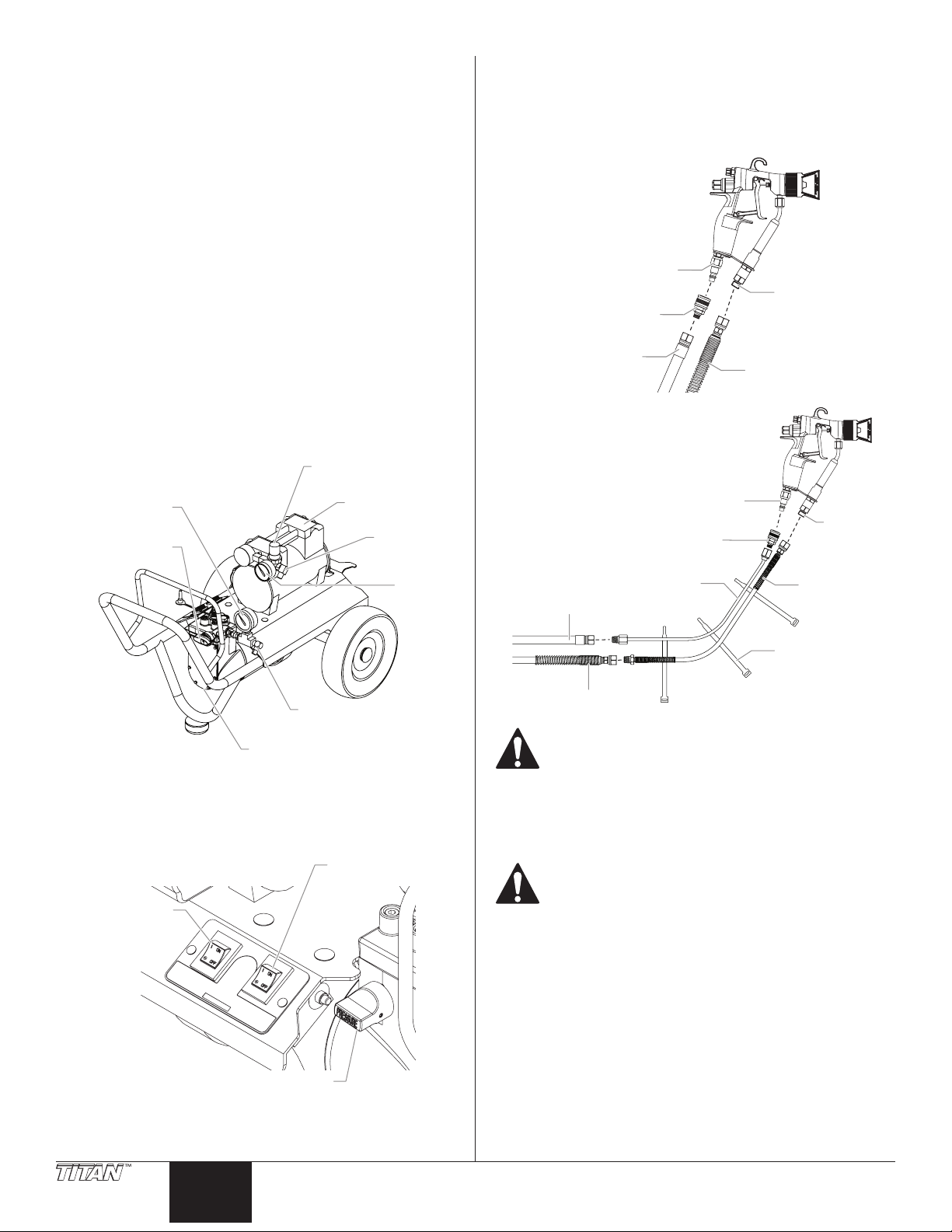
Table of Contents
Ma
Diaphragm Pump
e
Air Pressure
C
Pressure Control Knob
Pump ON/OFF
terial
Hose
Standard Hose
terial
Safety Precautions ........................................................................2-3
Grounding Instructions .............................................................................. 3
General Description ........................................................................ 4
Setup ................................................................................................ 4
Operation ......................................................................................... 5
Priming the Pump ........................................................................................ 5
Painting ............................................................................................................ 5
Pressure Relief Procedure .......................................................................... 7
Spraying Technique ........................................................................ 7
Cleanup ............................................................................................ 8
Overnight Storage ........................................................................................ 8
Long Term Storage ..................................................................................8-9
Maintenance .................................................................................. 10
Removing and Cleaning the Inlet Valve .............................................10
Removing and Cleaning the Outlet Valve .........................................10
Troubleshooting ............................................................................ 11
Parts List ......................................................................................... 32
Warranty ........................................................................................ 39
4. Using a wrench, attach a minimum of 50’ of 1/4” nylon airless
spray hose to the material outlet tting on the pump. Tighten
securely.
5. Attach the spray hose to the material inlet tting on the spray
gun. Using two wrenches (one on the gun and one on the
hose), tighten securely.
Conguration:
Air Inlet
Fitting
Coupling
Ma
Inlet
Fitting
General Description
This ne nish spray system is versatile enough to use for low
pressure ne nish work as well as high pressure airless spraying. The
system includes a diaphragm paint pump and an air compressor that
work together to provide this versatility.
Regulator
terial Pressure
Gauge
PRIME/SPRAY
Valve
Material
Outlet Fitting
Air Compressor
Air Outlet
Fitting
Air
Pressur
Gauge
Setup
Use this procedure to set up the spray system.
1. Make sure the pump ON/OFF switch and the compressor ON/
OFF switch are in the OFF position.
Air Hose
Material
With Optional
Whip Hoses:
Air Inlet
Fitting
Coupling
Air Whip
Air Hose
Material Hose
Make sure all airless hoses and spray guns are
electrically grounded and rated for at least 2800 PSI
(19 MPa) fluid pressure.
6. Attach the air hose to the air outlet tting on the compressor.
Tighten securely.
7. Attach the air hose coupling to the air inlet tting on the spray
gun. Attach the air hose to the coupling. Tighten securely.
Hose
Straps
Ma
Inlet
Fitting
Material
Whip Hose
2. Make sure the pressure control knob is turned fully
3. Lock the gun by ipping the trigger lock into lock position
4 © Titan Tool. All rights reserved.
Switch
ompressor
ON/OFF
Switch
counterclockwise to its lowest pressure setting.
(see spray gun manual).
English
Reversing the hose connections could result in serious
injury. Make sure the airless spray hose is connected
from the diaphragm pump to the material inlet fitting
on the gun and the air hose is connected from the
compressor to the air inlet fitting on the gun.
8. Make sure the electrical service is 120V, 15 amp minimum.
9. Plug the power cord into a properly grounded outlet at least
25’ from the spray area.
IMPORTANT: Always use a minimum 12 gauge, three-wire
extension cord with a grounded plug. Never remove the third
prong or use an adapter.
Page 5
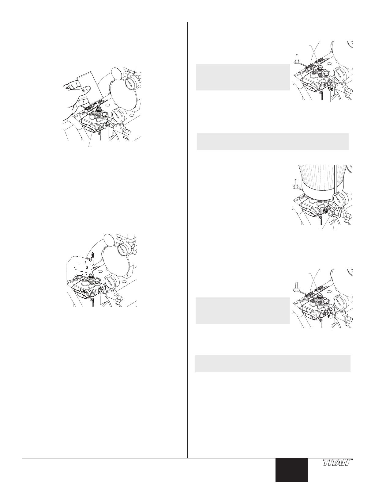
Operation
Valve
Return Tube Fitting
Inlet
Return
Tube
Inlet
Return Tube Fitting
Use the following procedures to operate the spray system.
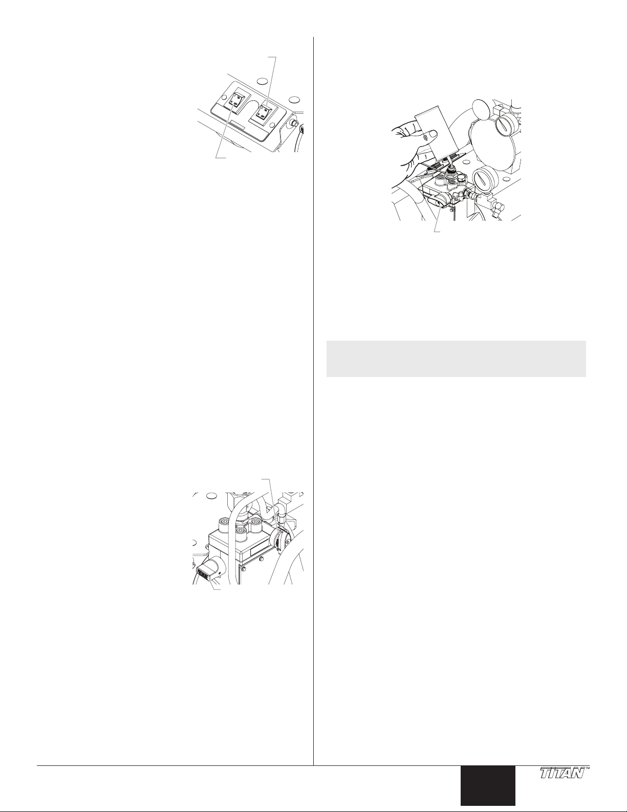
Priming the Pump
Preparing to Prime
1. Fill the inlet valve with water or with a light household oil.
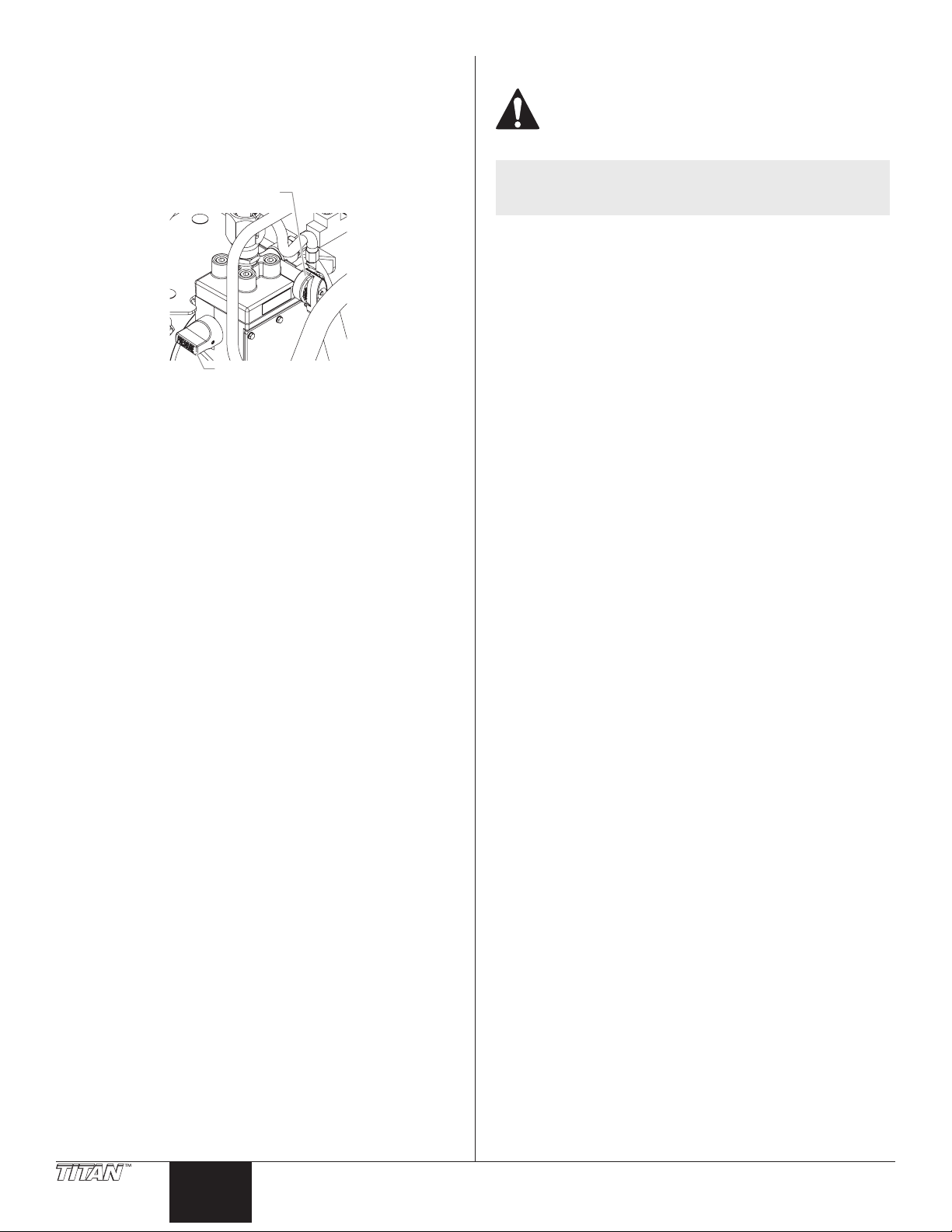
Mounting the Hopper Assembly
Use the following procedure to mount the paint hopper and attach
the return tube on a hopper unit.
1. Screw the return tube tting into
the return tube port on the side of
the pump.
NOTE: Do not over-tighten. Hand-
tighten only. Some threads
will be visible even when
fully tightened.
2. Align the bottom of the paint
hopper with the threaded inlet
valve on the paint pump block.
3. Turn the paint hopper clockwise to thread it onto the inlet
valve. Continue to turn the paint hopper until it is secure on
the inlet valve.
Valve
PRIME/SPRAY
2. Make sure that the PRIME/SPRAY valve is set to PRIME and that
the pressure control knob is turned counterclockwise to its
lowest pressure setting.
3. Turn on the pump by moving the pump ON/OFF switch to the
ON position.
4. Increase the pressure by turning the pressure control knob
clockwise 1/2 turn.
5. Force the inlet valve to open and close by pushing on it with
a screwdriver or the eraser end of a pencil. It should move up
and down about 1/16 of an inch. Continue until water or oil
is sucked into the pump. This will wet the moving parts and
break loose any old paint residue.
6. Put the palm of your hand over the inlet. Turn the pressure
control knob clockwise to its maximum setting. You should
feel suction coming from the inlet valve. If you do not, refer
to the “Removing and Cleaning the Outlet Valve” procedure in
the Maintenance section.
7. Turn the pressure control knob counterclockwise to the
minimum pressure setting.
8. Turn the pump ON/OFF switch to OFF.
NOTE: Make sure the threads are straight and the hopper
4. Place the lter screen into the bottom of the paint hopper and
5. Make sure that the motor ON/OFF
6. Place the straight end of the return
7. Thread the nut on the return tube
8. Place the hook end of the return
turns freely on the inlet valve. Do not cross-thread.
snap it in position.
switch is turned to OFF.
tube into the return tube tting.
onto the return tube tting and
tighten until the return tube is
secure.
tube into the hole in the paint
hopper cover.
Nut
Attaching the Optional Suction Set
Use the following procedure to attach the suction set to a suction set
unit.
1. Remove the hopper return tube
tting. Screw the return tube tting
into the return tube port on the
side of the pump.
NOTE: Do not over-tighten. Hand-
tighten only. Some threads
will be visible even when
fully tightened.
2. Align the nut on the suction set
with the threaded inlet valve on the
pump block.
3. Thread the suction hose nut onto the inlet valve on the pump.
NOTE: Make sure the threads are straight and the nut turns
freely on the inlet valve. Do not cross-thread.
Valve
© Titan Tool. All rights reserved. 5
4. Thread the return tube onto the return tube tting on the
pump.
English
Page 6
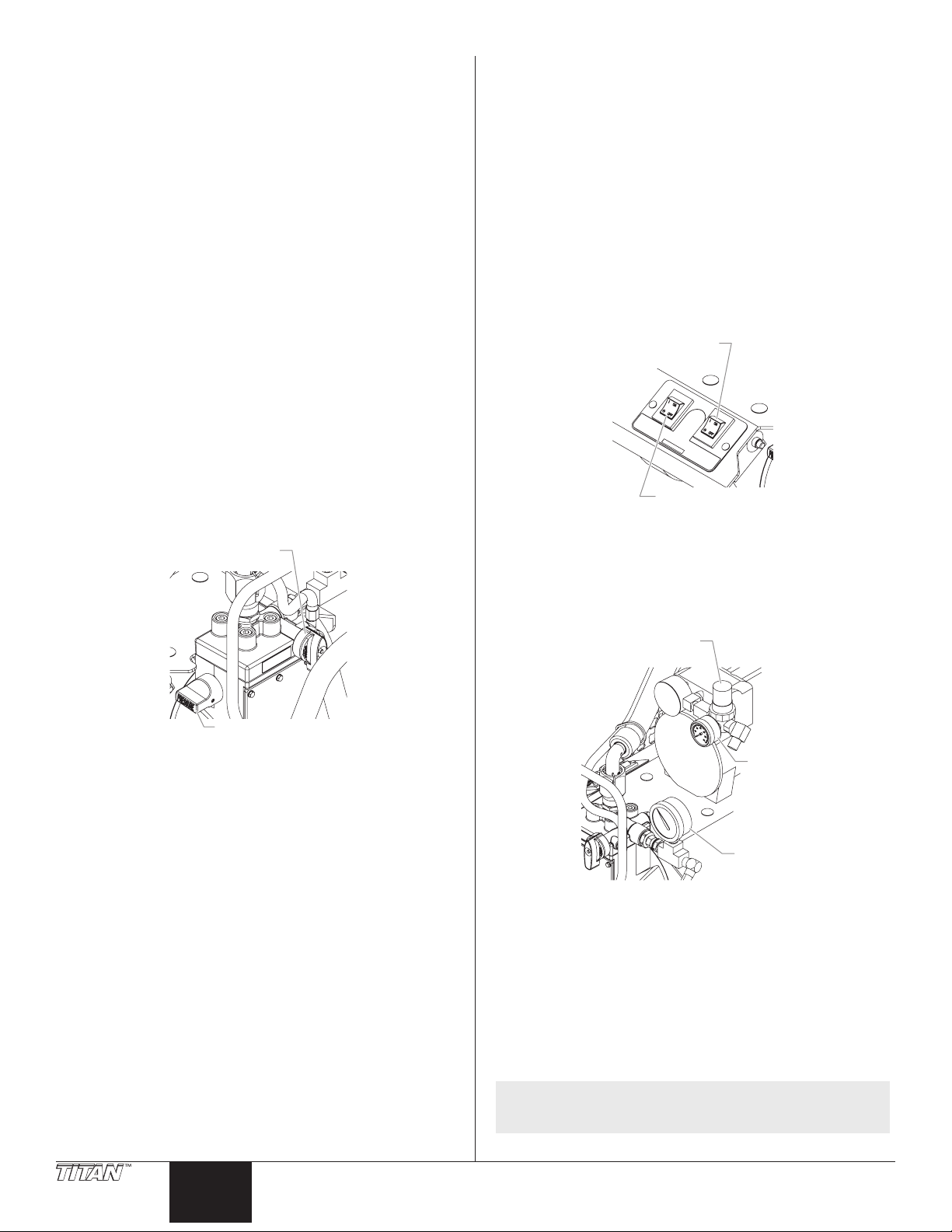
Priming with Hopper Assembly
PRIME/SPRAY
Control Knob
ON/OFF Switch
Pump ON/OFF
Air Pressure
1. Turn the pressure control knob counterclockwise to its lowest
pressure setting.
2. Remove the paint hopper cover and ll the paint hopper with
material or place the suction set into a bucket of material.
3. Turn the PRIME/SPRAY valve to PRIME.
4. Move the motor ON/OFF switch to ON.
5. Turn the pressure control knob clockwise to between half and
full pressure. Let the unit prime 1 to 2 minutes after material
begins to ow through the return tube.
IMPORTANT: Always reduce the pressure to zero before
changing the position of the PRIME/SPRAY valve. Failure to do
so may cause damage to the paint pump diaphragm.
IMPORTANT: If the pressure control knob is reduced to zero
and the PRIME/SPRAY valve is still on SPRAY while the sprayer is
operating, there will be high pressure in the hose and spray gun
until the PRIME/SPRAY valve is turned to PRIME or until the spray
gun is triggered to relieve the pressure.
Priming with Optional Suction Set
1. Place the suction set into a container of paint.
2. Turn the pressure control knob counterclockwise to the
minimum pressure setting.
IMPORTANT: Always reduce the pressure to zero by triggering
the spray gun before changing the position of the PRIME/SPRAY
valve. Failure to do so may cause damage to the paint pump
diaphragm.
3. Turn the PRIME/SPRAY valve to PRIME.
Valve
Painting
The AirCoat spray system has two dierent painting modes. The
AirCoat mode is used for ne nish work with low to medium
viscosity materials (oil, stains, lacquers, etc...). The airless mode is
used for general painting with high viscosity materials (latex).
Painting in AirCoat Mode
Use the AirCoat mode for low-pressure ne nish work
(recommended pump pressure up to 1000 PSI).
1. Make sure that the airless spray hose is free of kinks and clear
of objects with sharp cutting edges.
2. Turn the pressure control knob counterclockwise to its lowest
setting.
3. Turn the compressor air pressure regulator counterclockwise
to its lowest setting.
4. Move the compressor ON/OFF switch to the ON position.
5. Move the pump ON/OFF switch to the ON position.
Switch
Compressor
6. Turn the PRIME/SPRAY valve to SPRAY.
7. Turn the pressure control knob clockwise until the material
pressure gauge reads 400 PSI. The paint hose should stien as
paint begins to ow through it.
8. Turn the air pressure regulator clockwise until the air pressure
gauge reads 20 PSI.
Pressure
4. Move the pump ON/OFF switch to the ON position.
5. Turn the pressure control knob clockwise to between half
and full pressure. Let the unit prime 1 to 2 minutes after paint
begins to ow through the return hose until no bubbles are
present.
6. Turn the pressure control knob counterclockwise to the
minimum pressure setting.
7. Move the pump ON/OFF switch to the OFF position.
IMPORTANT: If the pressure control knob is reduced to zero
and the PRIME/SPRAY valve is still on SPRAY while the pump is
operating, there will be high pressure in the hose and spray gun
until the PRIME/SPRAY valve is turned to PRIME or until the spray
gun is triggered to relieve the pressure.
Regulator
Air
Air
Pressure
Pressure
Gauge
Gauge
Material
Material
Pressure
Pressure
Gauge
Gauge
9. Unlock the spray gun trigger.
10. Trigger the spray gun to bleed air out of the material hose.
11. When material reaches the spray tip, spray a test area to check
the spray pattern.
12. Adjust the spray pattern to the desired size and atomization.
a. Use the pressure control knob to control the ow of paint to the
gun.
b. Use the air pressure regulator to control the amount of atomization
air available to the gun.
c. Use the pattern adjustment knob on the gun to ne tune the spray
pattern.
NOTE: Refer to the spray gun Owner’s Manual for
information on the operation of the gun.
6 © Titan Tool. All rights reserved.
English
Page 7
Painting in Airless Mode
Paint tailing pattern
PRIME/SPRAY
Control Knob
Keep stroke smooth and at an even speed.
Even coat throughout
Heavy Coat
Do not ex wrist while spraying.
Light CoatLight Coat
Proper way to trigger the spray gun
Start stroke End strokePull trigger Release triggerKeep steady
Use the airless mode for general high-pressure spraying (pump
pressure from 500 to 2800 PSI).
1. Make sure that the airless spray hose is free of kinks and clear
of objects with sharp cutting edges.
2. Turn the pressure control
knob counterclockwise to its
lowest setting.
3. Turn the PRIME/SPRAY valve
to SPRAY.
4. Move the pump ON/OFF
switch to the ON position.
5. Turn the pressure control
knob clockwise to its highest
setting. The paint hose
should stien as paint begins
to ow through it.
6. Unlock the spray gun trigger.
7. Trigger the spray gun to
bleed air out of the material hose.
8. When material reaches the spray tip, spray a test area to check
the spray pattern.
9. Use the lowest pressure setting necessary to get a good spray
pattern. If the pressure is set too high, the spray pattern will
be too light. If the pressure is set too low, tailing will appear
or the paint will spatter out in “gobs” rather than in a ne
spray.
PRIME/SPRAY
Valve
Pressure
Control Knob
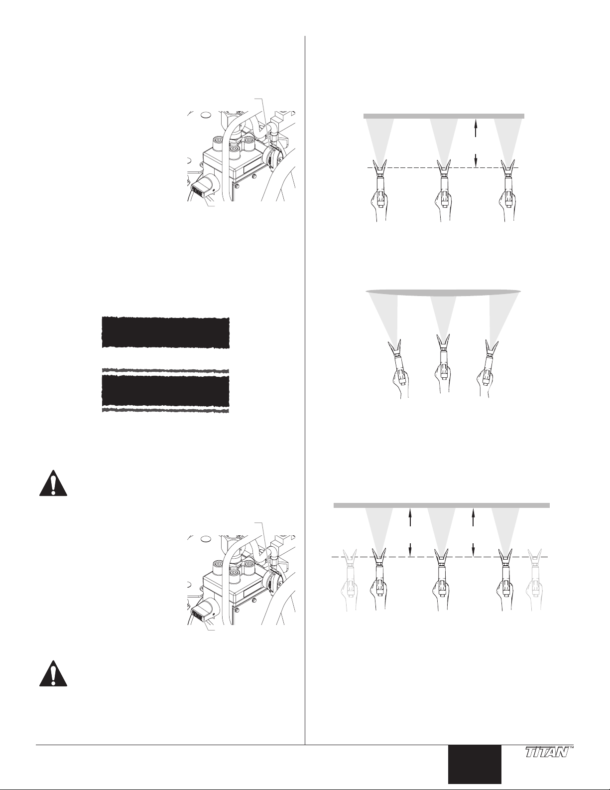
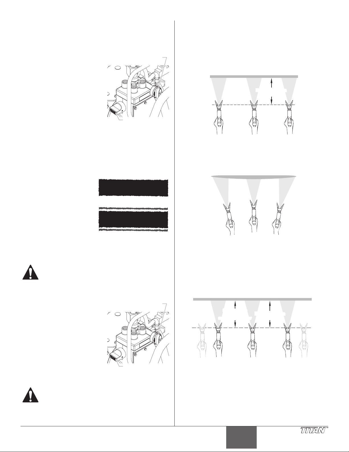
Spraying Technique
The key to a good paint job is an even coating over the entire surface.
This is done by using even strokes. Keep your arm moving at a
constant speed and keep the spray gun at a constant distance from
the surface. The best spraying distance is 10 to 12 inches between
the spray tip and the surface.
Approximately
10 to 12 inches
Keep the spray gun at right angles to the surface. This means moving
your entire arm back and forth rather than just exing your wrist.
Good spray pattern
Pressure Relief Procedure
Be sure to follow the pressure relief procedure when
shutting the unit down for any purpose, including
servicing or adjusting any part of the spray system,
changing or cleaning spray tips, or preparing for
cleanup.
1. Turn the pressure control
knob counterclockwise to its
lowest setting.
2. Turn the PRIME/SPRAY valve
to the PRIME position.
3. Trigger the gun to remove
any pressure that still may be
in the hose.
4. Lock the gun by ipping the
trigger lock into lock position
(see spray gun manual).
Injection hazard. Do not spray without the tip guard
in place. NEVER trigger the gun unless the tip is
completely turned to either the spray or the unclog
position. ALWAYS engage the gun trigger lock before
removing, replacing or cleaning tip.
Valve
Pressure
Keep the spray gun perpendicular to the surface, otherwise one end
of the pattern will be thicker than the other.
The spray gun should be triggered by turning it on and o with each
stroke. This will save paint and avoid paint buildup at the end of the
stroke. Do not trigger the gun during the middle of a stroke. This will
result in an uneven spray and splotchy coverage.
Keep stroke
even
Aproximately
10 to 12 inches
Overlap each stroke by about 30%. This will ensure an even coating.
When you stop painting, lock the gun trigger lock, turn the pressure
control knob counterclockwise to its lowest setting and set the
priming knob to PRIME. Turn the motor switch to OFF and unplug
the sprayer.
If you expect to be gone more than 1 hour, follow the short term
clean up procedure described in the Cleanup section of this manual.
© Titan Tool. All rights reserved. 7
English
Page 8
Cleanup
PRIME/SPRAY
Control Knob
Long-Term Storage
Overnight Storage
Shutdown
1. Turn the pressure control knob counterclockwise to the
minimum setting.
2. Turn the PRIME/SPRAY valve to PRIME.
Valve
Pressure
3. Move the pump ON/OFF switch to the OFF position.
4. Move the compressor ON/OFF switch to the OFF position.
5. Wait a couple seconds, then trigger the gun into the material
container to release built up uid pressure from the pump and
air pressure from the compressor.
6. Lock the gun by ipping the trigger lock into lock position
(see spray gun manual).
7. Unplug the unit.
8. For latex materials only, pour 1/2 cup water slowly on the
top of the paint to prevent the paint from drying. For other
materials, seal the material container keeping the return hose
in the paint.
9. Wrap the spray gun assembly in a damp cloth and place it in a
plastic bag. Seal the bag shut.
10. Place the unit in a safe place out of the sun for short-term
storage.
Startup
1. Remove the gun from the plastic bag.
2. Stir the water into the paint for latex materials. Remove the
cover from the material container and stir the paint for all
other materials.
3. Perform the appropriate procedure in the “Painting” section of
this manual for the type of spraying that will be performed.
Do not allow paint to build up on the motor or the
motor will overheat. Do not allow flammable solvents
to come in contact with the motor or they could ignite.
NOTE: If spraying with latex paint, use warm soapy water
for cleaning. If using oil or alkyd-based paints, use
mineral spirits or paint thinner.
IMPORTANT: Do not use mineral spirits or paint thinner on latex
paint, or the mixture will turn into a jelly-like substance which is
difficult to remove.
Clearing the Paint Hopper
Use the following procedure to clear the material out of the paint
hopper of a hopper unit.
1. Lock the gun by ipping the trigger lock into lock position
(see spray gun manual).
2. Turn the pressure control knob counterclockwise to the
minimum setting.
3. Turn the PRIME/SPRAY valve to PRIME.
4. Move the motor ON/OFF switch to OFF.
5. Direct the return tube into the original material container.
6. Move the motor ON/OFF switch to ON.
7. Turn the pressure control knob to 1/2 maximum pressure.
This will draw the remaining material in the paint hopper
through the pump, up the return tube, and into the material
container.
8. Turn the pressure control knob counterclockwise to the
minimum pressure setting.
9. Trigger the gun to relieve pressure and lock the gun.
10. Remove the spray tip and guard and place them into a
container of water or appropriate solvent for the type of
material with which you are painting.
11. Fill the paint hopper with water or an appropriate solvent for
the type of material with which you are painting.
12. Direct the return tube into a waste bucket.
13. Increase the pressure to 1/2 the maximum pressure. Let the
water or solvent circulate for 2-3 minutes to ush material out
of the pump, the paint hopper, and the return tube.
8 © Titan Tool. All rights reserved.
English
Page 9
Clearing the Suction Tube (optional)
PRIME/SPRAY
Control Knob
Valve
1. Turn the pressure control
knob counterclockwise to the
minimum setting.
2. Turn the PRIME/SPRAY valve to
PRIME.
3. Move the pump ON/OFF switch
to the OFF position.
4. Move the compressor ON/OFF
switch to the OFF position.
5. Wait a couple seconds, then
trigger the gun into the material
container to release built up uid
pressure from the pump and air
pressure from the compressor.
6. Lock the gun by ipping the trigger lock into lock position
(see spray gun manual).
7. Remove the suction hose from the material and hold it above
a bucket of water or solvent. Leave the return hose in the
material bucket.
IMPORTANT: Do not use mineral spirits or paint thinner on latex
paint, the mixture will turn into a jelly-like substance that is
difficult to remove.
8. Move the pump ON/OFF switch to the ON position.
9. Turn the pressure control knob to 1/2 maximum pressure.
This will draw the remaining material in the suction hose
through the pump, down the return hose and into the
material bucket.
10. Turn the pressure control knob counterclockwise to the
minimum setting.
11. Remove the spray tip and guard and place them into a
container of the appropriate solvent.
12. Place the attached suction hose and return hose into the
container of water or appropriate solvent.
13. Increase the pressure to 1/2 the maximum pressure. Let the
water or solvent circulate for 2-3 minutes to ush paint out of
the pump, the suction hose and the return hose.
Pump ON/OFF
Switch
Compressor
ON/OFF Switch
Clearing the Paint Hose
1. Turn the pressure control knob counterclockwise to the
minimum pressure setting.
2. Turn the PRIME/SPRAY valve
to SPRAY.
3. Unlock the spray gun trigger.
4. Carefully trigger the gun with
the spray tip removed against
the inside of the material
container.
5. Turn the pressure control
knob slowly clockwise until
material starts to ow into
the container. As soon as
the water or solvent starts to
emerge from the spray gun,
release the trigger.
6. Change to clean water or solvent and continue circulating for
another 5 minutes to thoroughly clean the hose, pump and
spray gun.
7. Turn the pressure control knob counterclockwise to its lowest
setting.
8. Turn the PRIME/SPRAY valve to PRIME.
9. Trigger the gun into the water or solvent container to release
built up uid pressure from the pump.
10. Lock the gun by ipping the trigger lock into lock position
(see spray gun manual).
11. Move the pump ON/OFF switch to the OFF position.
Valve
Pressure
Final Cleanup
1. Remove the hopper assembly or optional suction set from the
inlet valve.
2. Clean the threads of the inlet valve with a damp cloth.
3. Fill the inlet valve with water or with a light household oil.
PRIME/SPRAY
4. Make sure that the PRIME/SPRAY valve is set to PRIME and that
the pressure control knob is turned counterclockwise to its
lowest pressure setting.
5. Turn on the pump by moving the pump ON/OFF switch to the
ON position.
6. Increase the pressure by turning the pressure control knob
clockwise 1/2 turn.
7. Turn the PRIME/SPRAY valve to SPRAY to distribute the oil.
NOTE: Proper cleaning and oiling of the pump after use are
the most important steps to perform to insure proper
operation after storage.
8. Turn the pressure control knob counterclockwise to its lowest
setting.
9. Turn the PRIME/SPRAY valve to PRIME.
10. Unlock and trigger the gun to remove any pressure that may
still be in the hose.
11. Lock the gun by ipping the trigger lock into lock position
(see spray gun manual).
12. Turn o the pump by moving the pump ON/OFF switch to the
OFF position.
13. Remove the material hose and air hose from the spray gun
using two adjustable wrenches. Refer to the spray gun
Owner’s Manual for gun cleaning instructions.
14. Wipe the entire unit, hose, and gun with a damp cloth to
remove accumulated paint.
© Titan Tool. All rights reserved. 9
English
Page 10
Maintenance
Ball stop
Follow these procedures when encountering problems indicated in
the troubleshooting section.
Removing and Cleaning the Inlet Valve
1. Perform the Pressure Relief Procedure, turn o and unplug the
unit.
2. Remove the inlet valve assembly using a 27 millimeter socket
or box end wrench.
3. Test movement of the valve by pushing on it from the open
end of the valve housing with a screwdriver or the eraser end
of a pencil. It should move about 1/16 of an inch. If it does
not move, it should be cleaned or replaced.
NOTE: The inlet valve must be oiled
after every job. This will reduce
or eliminate priming problems
the next time the unit is used
as well as extend the life of the
valve.
4. Thoroughly clean the valve assembly with
water or the appropriate solvent. Use a small brush.
5. If the valve has been properly cleaned and water drips out of
the bottom, the valve is worn and needs to be replaced. A
properly seated valve lled with water and held vertically will
not drip.
6. Install a new or cleaned valve in the pump block and then ll
the valve with light oil or solvent.
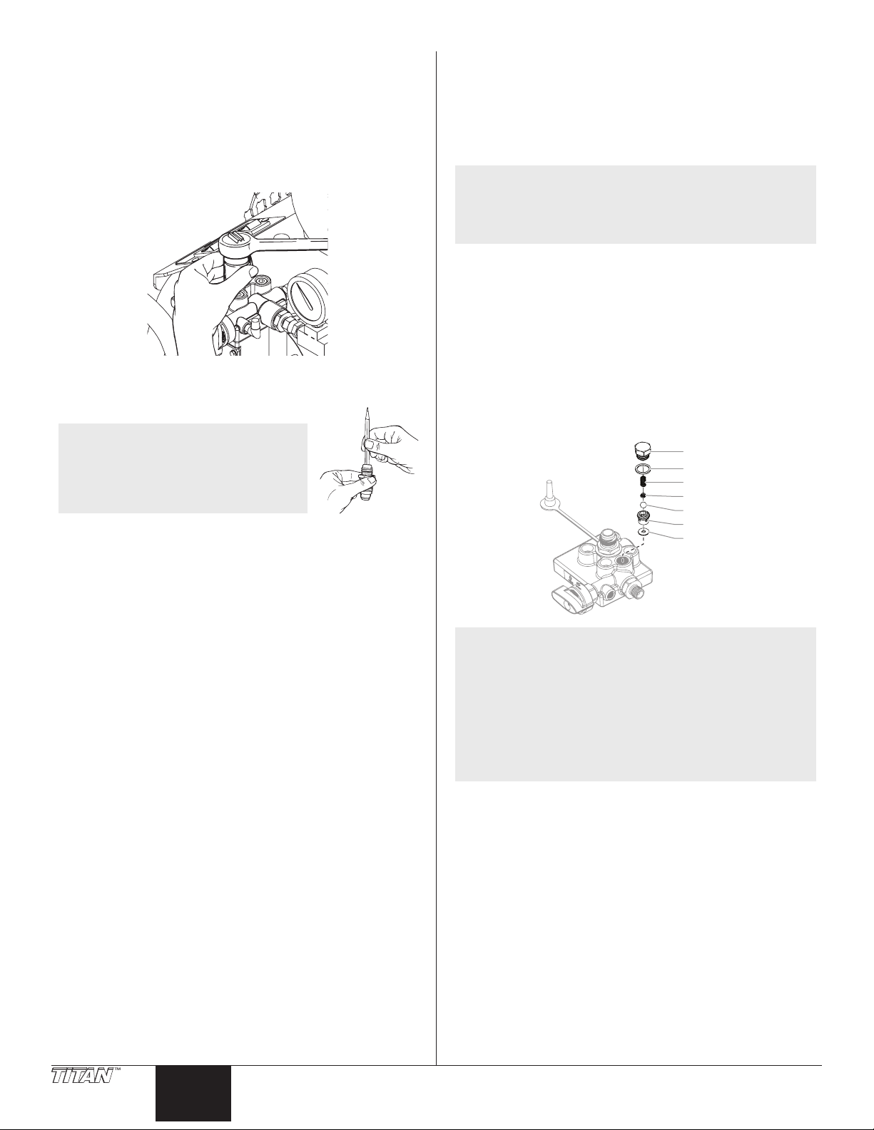
Removing and Cleaning the Outlet Valve
It may be necessary to remove and clean the outlet valve or to
replace parts inside the valve worn out through normal use.
1. Remove the outlet valve nut with a wrench.
2. Remove and clean the ball stop and small spring inside the
valve using a wire hook or tweezers. Replace the spring if it is
broken or worn.
NOTE: This spring is manufactured to a very specic
tension. Do not stretch the spring. Do not put in
an unauthorized substitute. See the paint pump
assembly parts diagram for the proper replacement
part number.
3. Remove the seat and ball assembly.
4. Clean all parts thoroughly. If the ball or seat show any sign of
wear or damage, replace them with new parts. This carbide
ball must seal tightly against its seat for the valve to function
properly.
5. Cover all parts with a thin coat of light oil before reassembling.
6. Drop in the valve ball.
7. Insert the protector and spring and replace the valve body.
Be sure that the O-ring is positioned properly and that the
tongue on the cap ts inside the spring.
8. Tighten the valve body securely with an adjustable wrench.
Do not over-tighten.
Nut
O-ring
Spring
Ball
Seat
Seal
NOTE: Wear on the ball is almost impossible to detect
visually. To test for a worn outlet valve assembly,
turn the pressure control knob clockwise to its
highest setting and run water only through the
pump for 10 to 15 minutes without triggering the
gun.
If the valve is defective, the end cap will get very hot
to the touch. If it is functioning properly, it will stay
approximately the same temperature as the water
running through it.
10 © Titan Tool. All rights reserved.
English
Page 11

Troubleshooting
Problem
A. The unit does not start up.
B. The pump starts up but does
not draw in paint when the
PRIME/SPRAY valve is set to
PRIME.
C. The pump draws up paint but
the pressure drops when the
gun is triggered.
D. The paint pattern is tailing.
E. The thermal overload tripped
and shut o the pump.
F. Compressor does not start.
G. Compressor starts but not
enough air.
Cause
1. The unit is not plugged in.
2. The ON/OFF switch is set to OFF.
3. A fuse is blown in the unit.
4. Low or no voltage is coming from the wall
plug.
5. The unit was turned o while still under
pressure.
6. The extension cord is damaged or has too low
a capacity.
7. The thermal overload on the unit is tripped.
8. There is a problem with the motor.
1. The pump will not prime properly or has lost
prime.
2. The paint bucket is empty or the suction hose
is not totally immersed in the paint.
3. The suction lter is clogged.
4. The suction hose is loose at the inlet valve.
5. The inlet valve is stuck.
6. The outlet valve is stuck.
7. The PRIME/SPRAY valve is plugged.
8. The inlet valve is worn or damage.
9. There is a problem with the diaphragm.
10. The hydraulic oil level is low or empty.
1. The spray tip is worn.
2. The suction set lter is clogged.
3. The gun or spray tip lter is plugged.
4. The paint is too heavy or coarse.
5. The outlet valve assembly is dirty or worn.
6. The inlet valve assembly is damaged or worn.
1. The uid pressure is set too low.
2. The air pressure is set too low.
3. The gun, the tip, or the suction lter is
plugged.
4. The suction hose is loose at the inlet valve.
5. The tip is worn.
6. The paint is too thick.
1. The motor overheated.
2. The extension cord is too long or is too small
a gauge.
3. Paint has built up on the motor.
4. The motor was started while the unit was
under pressure.
5. The unit was sitting in the hot sun.
1. The compressor ON/OFF switch is in the OFF
position.
2. Compressor ON/OFF switch is faulty.
3. Compressor is faulty.
4. Relief hole under air regulator is blocked.
1. Air regulator setting is too low.
2. Paint is too thick.
3. Closed air valve on gun.
4. Faulty pressure relief valve.
Solution
1. Plug the unit in.
2. Turn the ON/OFF switch to ON.
3. Replace the blown fuse with the proper replacement.
4. Properly test the power supply voltage.
5. Turn the PRIME/SPRAY knob to PRIME.
6. Replace the extension cord.
7. Allow the motor to cool and move the unit to a cooler
spot.
8. Take the unit to a Titan Authorized Service Center.
1. Try to prime the pump again.
2. Immerse the suction hose in paint.
3. Clean the suction set lter.
4. Clean the tube connection and tighten it securely.
5. Clean the inlet valve.
6. Clean the outlet valve and replace any worn parts.
7. Take the unit to a Titan Authorized Service Center.
8. Replace the inlet valve.
9. Take the unit to a Titan Authorized Service Center.
10. Take the unit to a Titan Authorized Service Center.
1. Replace the spray tip with a new tip.
2. Clean the suction set lter.
3. Clean or replace the proper lter. Always keep extra
lters on hand.
4. Thin or strain the paint.
5. Clean or replace the outlet valve assembly.
6. Replace the inlet valve.
1. Increase the uid pressure.
2. Increase the air regulator setting.
3. Clean the lters.
4. Tighten the suction hose tting.
5. Replace the spray tip.
6. Thin the paint.
1. Allow to cool for 30 minutes.
2. Allow to cool for 30 minutes and replace the extension
cord with a shorter extension or a thicker gauge cord.
3. Clean the paint from the motor.
4. Restart the unit in the PRIME mode.
5. Move the unit out of the sun.
1. Move the compressor ON/OFF switch to the ON position.
2. Take the unit to a Titan Authorized Service Center.
3. Take the unit to a Titan Authorized Service Center.
4. Clean out the relief hole.
1. Increase the air regulator setting.
2. Thin the paint.
3. Open the gun air valve. Refer to gun Owner’s Manual.
4. Install a new pressure relief valve.
United States Sales & Service
Phone:
Fax:
1770 Fernbrook Lane
Minneapolis, MN 55447
www.titantool.com
© Titan Tool. All rights reserved. 11
1-800-526-5362
1-800-528-4826
International
international@titantool.com
Fax: 1-763-519-3509
1770 Fernbrook Lane
Minneapolis, MN 55447
English
Page 12

Consignes de sécurite important
Prise trilaire
Lire toutes ces consignes avant d’utiliser l’appareil.
Garder ces consignes.
Indique une situation à risque, laquelle, si elle n’est pas
évitée, peut entraîner des blessures graves, voire la mort.
Pour réduire les risques d’incendie ou d’explosion,
de choc électrique et de blessure, vous devez lire et
comprendre les directives gurant dans ce manuel.
Familiarisez-vous avec les commandes et l’utilisation
adéquate de l’équipement.
Directives de mise à la terre
Cet appareil doit être mis à la terre. En cas de court-circuit, cette
précaution réduit les risques de choc en procurant un parcours
au courant électrique. Le cordon de l’appareil est doté d’un l de
terre relié à la troisième broche de sa che. Cette dernière doit être
branchée dans une prise correctement câblée et mise à la terre
conformément aux codes et règlements locaux.
MISE EN GARDE - Le fait de ne pas brancher
correctement la che trilaire de l’appareil peut
entraîner des risques de choc électrique.
Si on doit réparer ou remplacer le cordon ou la che, ne pas raccorder
le l de terre à la borne des broches plates (lames) de cette dernière.
Ce l, normalement vert (avec ou sans rayures jaunes), doit être relié
à la broche de terre.
Consulter un technicien ou un électricien qualié à défaut de
comprendre l’ensemble des présentes directives ou en cas
d’incertitude quant à la mise à terre de l’appareil. Ne pas modier la
che de l’appareil; si elle ne s’adapte pas dans la prise voulue, la faire
remplacer par un électricien qualié.
Conçu pour les circuits de 120 V, cet appareil est doté d’une che
ressemblant à celle illustrée ci-dessous. S’assurer que le produit est
connecté à une prise électrique ayant la même conguration que la
che mâle. Ne pas utiliser d’adaptateur avec ce produit.
Broche de mise à la terre
Plaque murale de la prise
NOTA : On ne recommande pas l’utilisation de rallonges de
MESURES PRÉVENTIVES :
• Ne pulvérisez pas de matières inammables ou combustibles
• S’entourer de toutes les précautions possibles lorsqu’on utilise
plus de 31 m (100 pi); il est préférable de rallonger
le tuyau à peinture que le cordon d’alimentation.
Les rallonges plus courtes assureront la puissance
électrique requise pour un fonctionnement
adéquat.
MISE EN GARDE : EXPLOSION OU INCENDIE
Les émanations de certains produits peuvent exploser
ou s’enammer, et risquent d’entraîner des dommages
matériels ou de graves blessures.
près d’une amme nue, de voyants lumineux ou de sources
d’ignition telles que des objets chauds, cigarettes, moteurs,
matériel et appareils électriques. Évitez de produire des
étincelles en connectant et en déconnectant les cordons
électriques.
des produits ayant un point d’éclair inférieur à 38°C (100°F).
Le point d’éclair est la température à laquelle le liquide peut
créer susamment de vapeurs et s’enammer.
• L’écoulement de peinture ou de solvant dans l’équipement
peut produire de l’électricité statique. L’électricité statique
crée un risque d’incendie ou d’explosion en présence de
fumées de peinture ou de solvant. Toutes les pièces du
système du pulvérisateur, y compris la pompe, l’ensemble
du tuyau, le pistolet de pulvérisation et les objets dans et
autour de la zone de pulvérisation doivent être correctement
reliés à la terre pour protéger contre les décharges
d’électricité statique et les étincelles. N’utilisez que des
tuyaux conducteurs ou reliés à la terre pour pulvérisateurs de
peinture sous vide à haute pression, spéciés par le fabricant.
• Vériez que tous les conteneurs ou systèmes de stockage sont
reliés à la terre pour éviter les décharges d’électricité statique.
• Connectez à une prise électrique avec prise de terre et utilisez
des rallonges électriques reliées à la terre. N’utilisez pas
d’adaptateur 3 à 2.
• N’utilisez pas de peinture ou de solvant contenant du halon,
par exemple, le chlore, les agents antimoisissure à l’eau
de Javel, le chlorure de méthylène et le trichloroéthane.
Ils ne sont pas compatibles avec l’aluminium. Contactez le
fournisseur de revêtements pour connaître la compatibilité du
matériau avec l’aluminium.
• La zone de pulvérisation doit toujours être bien aérée. Une
bonne quantité d’air frais doit constamment traverser la zone
de pulvérisation pour éviter les accumulations de vapeurs
inammables. Le système de pompage doit être placé
dans une zone bien aérée. Ne pulvérisez pas le système de
pompage.
• Ne fumez pas dans la zone de pulvérisation.
• N’actionnez pas d’interrupteurs électriques, de moteurs ou
autres dispositifs produisant des étincelles dans la zone de
pulvérisation.
• Maintenez la propreté de la zone et veillez à ce qu’elle ne
contienne pas de conteneurs de peinture ou de solvant, de
chions et autres matières inammables.
• Sachez ce que contiennent la peinture et les solvants
pulvérisés. Lisez les ches de sécurité du matériel (MSDS) et
les étiquettes apposées sur les conteneurs de peintures et de
solvants. Respectez les consignes de sécurité du fabricant de
peinture et de solvant.
• Placez la pompe à une distance minimum de 7,62 mètres
(25 pieds) de l’objet à pulvériser, dans une zone bien aérée
(ajoutez de la longueur de tuyau si besoin est). Les vapeurs
inammables sont souvent plus lourdes que l’air. La zone près
du sol doit être très bien aérée. La pompe contient des pièces
qui produisent des arcs et émettent des étincelles pouvant
enammer les vapeurs.
• Le plastique peut causer des étincelles d’électricité statique.
N’accrochez aucun plastique dans une zone de pulvérisation
fermée. N’utilisez pas de toiles de protection en plastique
quand vous pulvérisez une matière inammable.
• Ayez un extincteur en bon état de fonctionnement à portée de
main.
MISE EN GARDE : INJECTION CUTANÉE
Le jet de haute pression produit par cet appareil peut
transpercer la peau et les tissus sous-jacents, causant des
blessures graves pouvant entraîner l’amputation.
MESURES PRÉVENTIVES :
• Ne dirigez pas le pistolet sur et ne pulvérisez pas les personnes
ou les animaux.
• N’approchez pas les mains ni d’autres parties du corps de la
sortie du produit. Par exemple, ne tentez pas d’arrêter une
fuite avec une partie du corps.
• NE JAMAIS mettre la main, même gantée, devant le pistolet
(les gants n’orent aucune protection contre les blessures par
injection).
12 © Titan Tool. Tous droits réservés.
Français
Page 13

Consignes de sécurite important
• TOUJOURS s’assurer que le protège-embout est en place avant
de pulvériser. Il est cependant à noter que, s’il assure une
certaine protection, ce dispositif joue surtout un rôle préventif.
• Utilisez exclusivement un embout de buse spécié par le
fabricant.
• Prenez garde quand vous nettoyez ou que vous changez
les embouts de buse. Si l’embout se bouche pendant que
vous pulvérisez, verrouillez TOUJOURS la détente du pistolet,
arrêtez la pompe et libérez toute la pression avant de réparer
ou de nettoyer l’embout ou le protecteur ou avant de changer
d’embout. La pression n’est pas libérée par l’arrêt du moteur.
La poignée du robinet-valve PRIME/SPRAY doit être placée sur
PRIME pour libérer la pression. Consultez la PROCÉDURE DE
DÉCOMPRESSION décrite dans le manuel de la pompe.
• Ne laissez pas l’appareil sous tension ou sous pression
quand vous vous en éloignez. Quand vous n’utilisez pas
l’appareil, éteignez-le et libérez la pression conformément aux
instructions du fabricant.
• La pulvérisation à haute pression peut injecter des toxines
dans le corps et causer de graves blessures corporelles. Si une
telle injection se produisait, consultez immédiatement un
médecin.
• Vériez les tuyaux et les pièces pour détecter des signes
d’endommagement : une fuite peut injecter le produit dans
la peau. Inspectez le tuyau avant chaque emploi. Changez
tous les tuyaux ou pièces endommagés. Pour des raisons
de fonctionnement, de sécurité et de durée de vie, utiliser
exclusivement des tuyaux exibles à haute pression d‘origine
de TITAN.
• Ce système peut produire une pression de 2 800 PSI / 193
Bar. N’utilisez que les pièces de rechange ou les accessoires
spéciés par le fabricant et ayant une pression nominale
minimum de 2 800 PSI. Ceci est valable pour les embouts
de pulvérisation, les protecteurs de buse, les pistolets, les
rallonges, les raccords et le tuyau.
• Verrouillez toujours la détente quand vous ne pulvérisez pas.
Vériez que le verrou de la détente fonctionne correctement.
• Vériez que toutes les connexions sont bien serrées avant
d’utiliser l’appareil.
• Sachez comment arrêter l’appareil et le dépressuriser
rapidement. Soyez bien familiarisé avec les commandes. La
pression n’est pas libérée lorsque le moteur est arrêté. La
poignée du robinet-valve PRIME/SPRAY doit être placée sur
PRIME pour libérer la pression. Consultez la PROCÉDURE DE
DÉCOMPRESSION décrite dans le manuel de la pompe.
• Retirez toujours l’embout de pulvérisation avant de rincer ou
de nettoyer le système.
• Porter des lunettes de protection.
• Porter les vêtements de protection prescrits par le fabricant du
produit utilisé.
MISE EN GARDE : GÉNÉRALITÉS
D’autres dangers peuvent entraîner des dommages
matériels ou des blessures graves.
MESURES PRÉVENTIVES :
• Portez toujours les gants, la protection oculaire, les vêtements
et un respirateur ou masque appropriés quand vous peignez.
• Ne travaillez pas et ne pulvérisez pas près d’enfants. Éloignez
toujours les enfants de l’équipement.
• Ne travaillez pas avec les bras au-dessus de la tête ni sur un
support instable. Appuyez-vous bien sur les deux pieds pour
toujours conserver l’équilibre.
• Soyez attentif et regardez ce que vous faites.
• N’utilisez pas l’appareil quand vous êtes fatigué ou sous
l’inuence de drogues ou d’alcool.
• Ne faites pas de nœuds avec le tuyau et ne le tordez pas trop.
Le tuyau à vide peut présenter des fuites suite à l’usure, les
nœuds ou les mauvais traitements. Une fuite risque d’injecter
du produit dans la peau.
• N’exposez pas le tuyau à des températures ou des pressions
supérieures à celles spéciées par le fabricant.
• N’utilisez pas le tuyau pour tirer ou soulever l’équipement.
• Utilisez la plus basse pression possible pour rincer
l’équipement.
• Respectez tous les codes locaux, étatiques et nationaux
qui régulent la ventilation, la prévention d’incendies et le
fonctionnement.
• Les normes de sécurité du gouvernement des États-Unis ont
été adoptées dans la loi Occupational safety and Health Act
(OSHA). Ces normes, en particulier la partie 1910 des Normes
générales et la partie 1926 des Normes de construction,
doivent être consultées.
• Avant chaque emploi, vériez tous les tuyaux pour détecter
d’éventuelles coupures, fuites, abrasion ou couvercle bombé.
Vériez l’état ou le mouvement des accouplements. Changez
immédiatement le tuyau si l’une de ces conditions est vériée.
Ne réparez jamais un tuyau de peinture. Remplacez-le par un
tuyau conducteur à haute pression.
• Ne pulvérisez pas à l’extérieur par temps venteux.
• Débranchez toujours le cordon électrique de la prise avant de
travailler sur l’équipement.
REMARQUE À L’INTENTION DES MÉDECINS : Les injections
cutanées sont des lésions traumatiques; il importe donc de
les traiter sans délai. On NE DOIT PAS retarder ce traitement
sous prétexte de vérier la toxicité du produit en cause, celle-ci
n’étant conséquente que dans le cas d’injection directe de
certains produits dans le système sanguin. Il pourrait s’avérer
nécessaire de consulter un plasticien ou un spécialiste en
chirurgie reconstructive de la main.
MISE EN GARDE : ÉMANATIONS DANGEREUSES
Certains produits (peintures, solvants, insecticides ou
autres) peuvent être nocifs s’ils sont inhalés ou entrent en
contact avec l’organisme. Les émanations de ces produits
peuvent provoquer de graves nausées, évanouissements
ou empoisonnements.
MESURES PRÉVENTIVES :
• Se servir d’un masque ou d’un respirateur s’il y a risque
d’inhalation (lire toutes les directives concernant ces
dispositifs an de s’assurer qu’ils orent la protection requise).
© Titan Tool. Tous droits réservés. 13
IMPORTANT: La pompe à diaphragme est dotée d’un dispositif
de remise en marche automatique avec protection thermique.
En cas de surcharge, ce dispositif débranche le moteur du bloc
d’alimentation.
• Le moteur se remet en marche sans avertissement lorsque le
protecteur est réarmé automatiquement.
• Débranchez toujours le moteur du bloc d’alimentation avant
d’utiliser l’équipement.
• Lorsque le dispositif de remise en marche automatique
débranche le moteur du bloc d’alimentation, libérez de la
pression en tournant la soupape de PRIME/SPRAY à la position
PRIME.
• Placez l’interrupteur MARCHE/ARRÊT (ON/OFF) de la pompe
en position ARRÊT (OFF).
NOTA : Il faut remédier à la cause de la surcharge avant
de faire redémarrer la pompe. Voir la section
Dépannage.
Français
Page 14
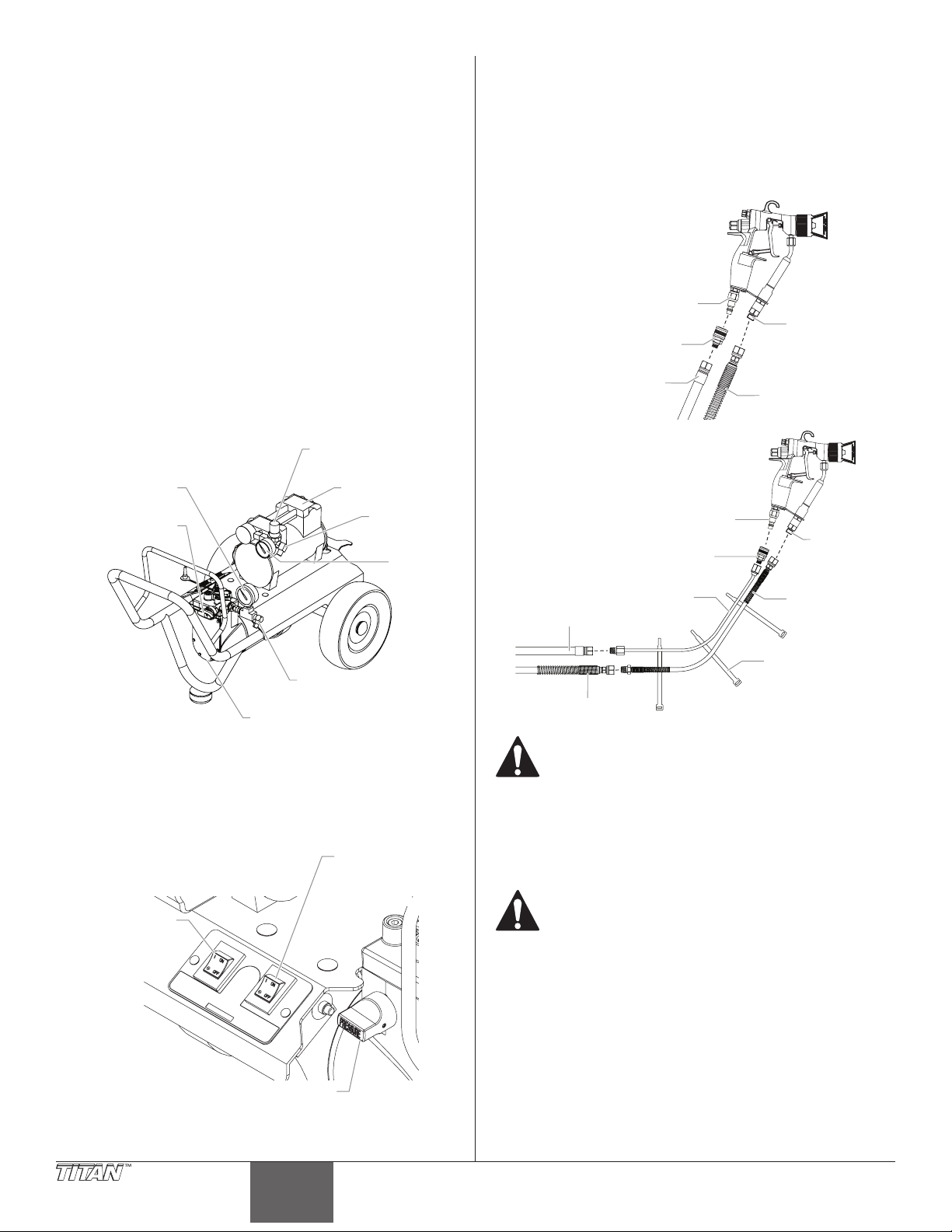
Table des matières
Pompe à diaphragme
Jauge de
Régulateur
Jauge de pression
MAR
du compresseur
Bouton de réglage de la pression
Interrupteur
t
C
t
Consignes de sécurité ..............................................................12-13
Description générale ..................................................................... 14
Installation ..................................................................................... 14
Fonctionnement ............................................................................ 15
Amorçage de la pompe ............................................................................15
Peinture ..........................................................................................................15
Procédure de limitation de la pression ...............................................17
Technique de pulvérisation .......................................................... 17
Nettoyage ...................................................................................... 18
Rangement pour la nuit ...........................................................................18
Rangement à long terme .................................................................. 18-19
Maintenance .................................................................................. 20
Démontage et nettoyage de la soupape d’admission ..................20
Démontage et nettoyage de la soupape de sortie ........................20
Dépannage ..................................................................................... 21
Liste de pièces ................................................................................ 32
Garantie Limitée ............................................................................ 40
Description générale
Ce système de pulvérisation à haute précision est un outil polyvalent
pouvant être utilisé tant pour des travaux de nition à basse pression
que pour la pulvérisation haute pression sans air comprimé. Le
système comprend une pompe à peinture à diaphragme et un
compresseur à air qui fonctionnent ensemble et lui donne ce
caractère polyvalent.
de pression
de l'air
du produit
Soupape de
PRIME/SPRAY
Compresseur
d'air
Raccord
de sortie
d'air
pression
de l'air
3. Verrouillez le pistolet en enclenchant le cran de sûreté (voir le
Guide d’utilisation du pistolet).
4. À l’aide d’une clé, xez un tuyau de pulvérisation sans air en
nylon d’un diamètre de 6,4 mm (1/4 po) et d’une longueur
minimale de 15 m (50 pi) sur le raccord de sortie du produit de
la pompe. Serrez fermement.
5. Fixez le tuyau de pulvérisation sur le raccord d’entrée du
produit. À l’aide de deux clés (une sur le pistolet et l’autre sur
le tuyau), serrez fermement.
onguration standard
Avec l'option de
Tuyau d’air
des tuyaux:
d'admission de l'air
Raccord
Tuyau d’air
fouet tuyau :
d'admission de l'air
Fouet tuyau
Raccord
Raccord
d’air
Raccord
Raccord
d’entrée
du produi
Tuyau du
produit
Fouet tuyau
de produit
Raccord
d’entrée
du produi
Installation
Procédez comme suit pour mettre le système de pulvérisation en
marche.
1. Assurez-vous que l’interrupteur MARCHE/ARRÊT de la pompe
2. Assurez-vous que le bouton de réglage de la pression est
14 © Titan Tool. Tous droits réservés.
Raccord de sortie
du produit
et que l’interrupteur MARCHE/ARRÊT du compresseur se
trouvent sur la position ARRÊT (OFF).
MARCHE/ARRÊT
(ON/OFF)
de la pompe
Interrupteur
CHE/ARRÊT
(ON/OFF)
complètement tourné dans le sens inverse des aiguilles d’une
montre, réglé sur la pression la plus basse.
Français
Courroies
Tuyau du produit
Assurez-vous que tous les tuyaux sans air comprimé
et les pistolets de pulvérisation sont bien raccordés
électriquement et peuvent fonctionner à une pression
de fluide d’au moins 2,800 PSI (19 MPa).
6. Montez le tuyau d’air sur le raccord de sortie d’air du
compresseur. Serrez fermement.
7. Montez le raccord du tuyau d’air sur le raccord d’entrée
d’air du pistolet. Montez le tuyau d’air sur le raccord. Serrez
fermement.
L’inversion des raccords de tuyaux peut occasionner
des lésions corporelles graves. Assurez-vous que le
tuyau de pulvérisation sans air comprimé est bien
branché à la pompe à diaphragme sur le raccord
d’entrée du produit du pistolet et que le tuyau à air
est bien branché entre le compresseur et le raccord
d’entrée d’air du pistolet.
8. Assurez-vous que le réseau électrique est de 120 V, et au
minimum de 15 A.
9. Branchez le cordon d’alimentation sur une prise reliée à la
terre à une distance minimale de 7,6 m (25 pi) cm de la zone
de vaporisation.
IMPORTANT: Utilisez toujours une rallonge électrique trifilaire
de calibre 12 munie d’une fiche mise à la terre. Vous ne devez
jamais enlever la troisième broche ni utiliser un adaptateur.
Page 15
Fonctionnement
PRIME/SPRAY
Soupape
Tube de
retour
Soupape
Raccord de tube de retour
Procédez comme suit pour mettre le système de pulvérisation en
marche.
Amorçage de la pompe
Préparation de l’amorçage
1. Remplissez la soupape d’entrée d’eau ou d’huile ménagère
légère.
Assemblage de la trémie de peinture
Procédez comme suit pour assembler la trémie de peinture et xer le
tube de retour sur la trémie.
1. Vissez le raccord du tube de
retour dans l’orice du tube de
retour, sur le côté de la pompe.
NOTA : Ne serrez pas trop. Serrez
seulement à la main.
Certains lets seront
visibles même après
avoir serré à fond.
2. Alignez le bas de la trémie
de peinture avec le robinet
d’entrée leté du bloc de la pompe à peinture.
3. Tournez la trémie dans le sens des aiguilles d’une montre pour
la visser sur le robinet d’entrée. Continuez à tourner la trémie
jusqu’à ce qu’elle soit bloquée sur le robinet d’entrée.
d’entrée
Raccord de tube de retour
Soupape de
2. Assurez-vous que la soupape de PRIME/SPRAY est bien
placée sur la position PRIME et que le bouton de réglage de
la pression est complètement tourné dans le sens inverse des
aiguilles d’une montre, réglé sur la pression la plus basse.
3. Allumez la pompe en plaçant l’interrupteur MARCHE/ARRÊT
(ON/OFF) de la pompe à la position MARCHE (ON).
4. Augmentez la pression en faisant tourner le bouton de
réglage de la pression dans le sens des aiguilles d’une montre
d’un demi-tour.
5. Ouvrez la soupape d’admission et fermez-la en appuyant
dessus avec un tournevis ou la gomme à eacer de l’extrémité
d’un crayon. Elle doit monter et descendre d’environ 1,6
mm (1/16 po). Poursuivez cette action jusqu’à ce que l’eau
ou l’huile soit aspirée dans la pompe ce qui humidiera les
parties mobiles et délogera toute trace de peinture résiduelle.
6. Placez la paume de votre main sur l’orice d’entrée. Tournez
complètement le bouton de réglage de la pression dans le
sens des aiguilles d’une montre. Vous devriez sentir qu’il y a
une aspiration dans la soupape d’admission. Si ce n’est pas
le cas, consultez la rubrique Démontage et nettoyage de la
soupape de sortie dans la section Maintenance.
7. Tournez le bouton de réglage de la pression dans le sens
inverse des aiguilles d’une montre jusqu’à ce que la valeur de
pression minimum soit atteinte.
8. Placez l’interrupteur MARCHE/ARRÊT (ON/OFF) de la pompe
en position ARRÊT (OFF).
NOTA : Vériez que les lets sont droits et que la trémie est
4. Placez le crépine dans le bas de la trémie de peinture. Il se met
5. Assurez-vous que l’interrupteur
6. Placez l’extrémité droite du tube
7. Vissez l’écrou du tube de retour
8. Placez l’extrémité en forme de
libre de tourner sur le robinet d’entrée. Veillez à ne
pas visser de travers.
en place par un coup sec.
ON/OFF du moteur est placé sur
OFF.
de retour dans le raccord du tube.
sur le raccord du tube de retour et
serrez jusqu’à ce que le tube soit
xé.
crochet du tube de retour dans le
trou du couvercle de la trémie de
peinture.
Écrou
Assemblage le optional ensemble d’aspiration
Procédez comme suit pour xer le ensemble d’aspiration à l’unité
d’aspiration.
1. Retirez le raccord de tube de
retour de trémie. Vissez le
raccord du tube de retour dans
l’orice du tube de retour sur le
côté de la pompe.
NOTA : Ne serrez pas trop. Serrez
seulement à la main.
Certains lets seront
visibles même après
avoir serré à fond.
2. Alignez l’écrou du groupe d’aspiration avec le robinet d’entrée
leté du bloc de la pompe à peinture.
3. Montez et serrez l’écrou du tuyau d’aspiration sur la soupape
d’admission de la pompe.
NOTA : Vériez que les lets sont droits et que l’écrou tourne
sans problème sur le robinet d’entrée. Veillez à ne
pas visser de travers.
d’entrée
© Titan Tool. Tous droits réservés. 15
4. Montez et serrez le tuyau de retour sur le raccord du tuyau de
retour de la pompe.
Français
English
Page 16
Amorçage avec de la trémie de peinture
Soupape de
de la pression
T
(ON/OFF) du compresseur
Interrupteur MARCHE/ARRÊT
Régulateur de pression de l'air
Jauge de pression
1. Tournez le bouton de commande de pression dans le sens
contraire des aiguilles d’une montre jusqu’au réglage de
pression le plus bas.
2. Retirez le couvercle de la trémie de peinture et remplissez la
trémie ou bien placez le groupe d’aspiration dans un seau de
peinture.
3. Tournez le soupape de PRIME/SPRAY sur PRIME.
4. Placez l’interrupteur ON/OFF du moteur sur ON.
5. Tournez le bouton de commande de pression dans le sens
des aiguilles d’une montre sur la position intermédiaire entre
demi-pression et pression totale. Laissez l’unité s’amorcer
pendant 1 à 2 minutes après que la peinture commence à
s’écouler dans le tube de retour.
IMPORTANT : Abaissez toujours la pression à zéro avant de
modifier la position du soupape de PRIME/SPRAY. Vous pourriez
sinon endommager la membrane de la pompe à peinture.
IMPORTANT : Si le bouton de commande de pression est placé
sur zéro et que le soupape de PRIME/SPRAY est encore sur
SPRAY pendant que le pulvérisateur est en marche, il y aura une
pression élevée dans le tuyau et dans le pistolet de pulvérisation
jusqu’à ce que le soupape de PRIME/SPRAY soit placé sur la
position PRIME ou jusqu’à ce que la pression soit dégagée sur le
pistolet.
Amorçage avec optional l’ensemble d’aspiration
1. Placez le tuyau d’aspiration dans un contenant de peinture.
2. Tournez le bouton de réglage de la pression dans le sens
inverse des aiguilles sur le réglage de pression minimale.
IMPORTANT: Réduisez toujours la pression à zéro par le
déclenchement de pistolet avant de changer la position de
la soupape de PRIME/SPRAY. Le diaphragme de la pompe à
peinture pourrait s’endommager si cette consigne n’est pas
respectée.
3. Placez la soupape de PRIME/SPRAY en position PRIME.
PRIME/SPRAY
Peinture
Le système de pulvérisation AirCoat dispose de deux modes de
peinture diérents : le mode AirCoat, utilisé pour les travaux de
nition précis exécutés avec des produits peu ou moyennement
visqueux (huile, vernis, laques, etc.) Le mode sans air, utilisé pour la
peinture général avec des matériaux très visqueux (latex).
Peinture en mode AirCoat
Utilisez le mode AirCoat pour les travaux de nition à basse pression
(pression de la pompe recommandée de 1 000 PSI maximum).
1. Assurez-vous que le tuyau de pulvérisation sans air n’est pas
plié et qu’il ne touche pas des objets aux bords coupants.
2. Tournez le bouton de réglage de la pression dans le sens
inverse des aiguilles d’une montre jusqu’au réglage minimum.
3. Tournez le régulateur de pression de l’air du compresseur
dans le sens inverse des aiguilles d’une montre jusqu’au
réglage minimum.
4. Placez l’interrupteur MARCHE/ARRÊT (ON/OFF) du
compresseur en position MARCHE (ON).
5. Placez l’interrupteur MARCHE/ARRÊT (ON/OFF) en position
MARCHE (ON).
(ON/OFF) de la pompe
Interrupteur MARCHE/ARRÊ
6. Placez la soupape de PRIME/SPRAY en position SPRAY.
7. Tournez le bouton de réglage de la pression dans le sens des
aiguilles d’une montre jusqu’à ce que la jauge de pression
du produit atteigne 400 PSI. Le tuyau à peinture doit goner
lorsque la peinture commence à s’y écouler.
8. Tournez le bouton de réglage de la pression dans le sens des
aiguilles d’une montre jusqu’à ce que la jauge de pression de
l’air atteigne 20 PSI.
4. Placez l’interrupteur MARCHE/ARRÊT (ON/OFF) en position
MARCHE (ON).
5. Tournez le bouton de réglage de la pression dans le sens des
aiguilles d’une montre et placez-le entre la pression maximale
et pression moyenne. Amorcez la pompe pendant 1 à 2
minutes après que la peinture a commencé à couler par le
tuyau de retour et jusqu’à ce qu’il n’y ait plus de bulles.
6. Tournez le bouton de réglage de la pression dans le sens
inverse des aiguilles sur le réglage de pression minimale.
7. Placez l’interrupteur MARCHE/ARRÊT (ON/OFF) en position
ARRÊT (OFF).
IMPORTANT: Si le bouton de réglage de la pression est tourné à
zéro et que la soupape de PRIME/SPRAY est toujours en position
spray pendant que la pompe fonctionne, il y aura une pression
élevée dans le tuyau et dans le pistolet de pulvérisation jusqu’à
ce que la soupape de PRIME/SPRAY soit placée en position prime
ou que le pistolet de pulvérisation soit enclenché pour réduire la
pression.
16 © Titan Tool. Tous droits réservés.
Bouton de réglage
Français
de l'air
Jauge de pression
du produit
9. Débloquez le détente de pistolet.
10. Enclenchez le pistolet de pulvérisation pour purger l’air du
tuyau réservé au produit.
11. Lorsque le produit atteint la tête de pulvérisation, il faut peindre
une zone d’essai pour vérier la forme du jet de pulvérisation.
12. Réglez la forme de pulvérisation selon la taille et l’atomisation
souhaitées.
a. Utilisez le bouton de réglage de la pression pour contrôler le jet de
peinture vers le pistolet.
b. Utilisez le bouton de réglage de la pression de l’air pour contrôler
la quantité d’air de pulvérisation disponible vers le pistolet.
c. Utilisez le bouton de réglage de forme du pistolet pour aner la
forme de pulvérisation.
NOTA : Consultez le manuel de l’utilisateur du pistolet de
pulvérisation pour plus de détails concernant le
fonctionnement du pistolet.
Page 17
Peinture en mode sans air
Revêtement également répartit
régulier et à vitesse constante.
Couche épaisse
Ne échissez pas votre poignet pendant la pulvérisation.
Couche légèreCouche légère
Manière correcte d'enclencher le pistolet de pulvérisation
Début du
assage
du passage
sur la gâchette
la gâchette
itesse constante
Utilisez le mode sans air pour les travaux de pulvérisation généraux à
haute pression (pression de la pompe variant entre 500 à 2 800 PSI).
1. Assurez-vous que le tuyau de pulvérisation n’est pas plié et
qu’il ne touche pas des objets aux bords coupants.
2. Tournez le bouton de réglage
de la pression dans le sens
inverse des aiguilles d’une
montre jusqu’au réglage
minimum.
3. Placez la soupape de PRIME/
SPRAY en position SPRAY.
4. Placez l’interrupteur
MARCHE/ARRÊT (ON/OFF) en
position MARCHE (ON).
5. Tournez le bouton de réglage
de la pression dans le sens
des aiguilles d’une montre
au maximum. Le tuyau à
peinture doit goner lorsque
la peinture commence à s’y écouler.
6. Débloquez le détente de pistolet.
7. Enclenchez le pistolet de pulvérisation pour purger l’air du
tuyau réservé au produit.
8. Lorsque le produit atteint la tête de pulvérisation, il faut
peindre une zone d’essai pour vérier la forme du jet de
pulvérisation.
9. Pulvérisez toujours à
la pression minimale
nécessaire pour obtenir
les résultats souhaités. Si
la pression du système
Forme de pulvérisation correcte
est trop élevée, la forme
de pulvérisation sera trop
légère. Si la pression est
trop faible, des traînées
apparaissent ou la peinture
est projetée en « gouttes »
au lieu d’être pulvérisée.
Traînées de peinture
Procédure de limitation de la pression
Assurez-vous de bien suivre la procédure de limitation
de pression lorsque vous arrêtez l’appareil pour une
raison quelconque, y compris lors de l’entretien ou
du réglage d’une pièce du circuit de vaporisation,
du remplacement ou du nettoyage des embouts de
vaporisation ou lors de la préparation au nettoyage.
1. Tournez le bouton de réglage
de la pression dans le sens
inverse des aiguilles d’une
montre jusqu’au réglage
minimum.
2. Tournez la soupape PRIME/
SPRAY en position SPRAY.
3. Enclenchez le pistolet pour
éliminer toute pression qui
pourrait se trouver dans le
tuyau.
4. Verrouillez le pistolet en
enclenchant le cran de sûreté
(voir le Guide d’utilisation du
pistolet).
Danger de blessure par injection. Ne vaporisez pas
si l’embout de protection de la tête n’est pas en
place. Ne déclenchez JAMAIS le pistolet si la tête de
pulvérisation n’est pas en position de pulvérisation
ou de décolmatage. Engagez TOUJOURS le dispositif
de verrouillage de la gâchette du pistolet avant de
démonter, de remplacer ou de nettoyer la tête.
Soupape de
PRIME/SPRAY
Bouton de réglage
de la pression
Soupape de
PRIME/SPRAY
Bouton de réglage
de la pression
Technique de pulvérisation
Pour obtenir une peinture d’un ni impeccable il est essentiel que le
produit soit également réparti sur toute la surface. Pour y parvenir,
procédez par applications régulières. Déplacez votre bras à vitesse
constante et gardez toujours le pistolet de pulvérisation à une
distance constante de la surface. Placez votre pistolet de telle sorte
que la tête de pulvérisation soit à une distance d’environ 25 à 30 cm
(10 à 12 po) de la surface.
Environ 25 à 30 cm
(10 à 12 po)
Déplacez votre bras d’un mouvement
Gardez le pistolet de pulvérisation à angle droit par rapport à la
surface. Il vous faut pour cela déplace tout votre bras de haut en bas
et non pas seulement échir votre poignet.
Placez le pistolet de pulvérisation perpendiculaire à la surface, an
d’éviter qu’une extrémité de chaque passage soit plus épaisse que
l’autre.
Appuyez sur la gâchette au début et à la n de chaque passage. Vous
éviterez de gaspiller de la peinture ou d’avoir une accumulation de
peinture à l’extrémité du passage. N’enclenchez pas le pistolet au
milieu d’un passage. Ceci entraînerait une pulvérisation inégale et un
revêtement irrégulier.
Déplacez votre
bras d’un
mouvement régulier
Appuyez
Chevauchez chaque passage d’environ 30 %. Vous obtiendrez ainsi
un revêtement uniforme.
Lorsque vous avez terminé de peindre, bloquez le pistolet, tournez le
bouton de réglage de la pression dans le sens contraire des aiguilles
d’une montre sur la pression la plus faible et placez le soupape de
PRIME/SPRAY sur prime. Placez l’interrupteur du moteur en position
ARRÊT (OFF) puis débranchez le pulvérisateur.
Si vous pensez être absent pendant plus d’une heure, suivez la
procédure de nettoyage rapide décrite dans la section Nettoyage du
présent manuel.
Environ 25 à 30 cm
Gardez une
(10 à 12 po)
Relâchez
Fin
© Titan Tool. Tous droits réservés. 17
Français
English
Page 18
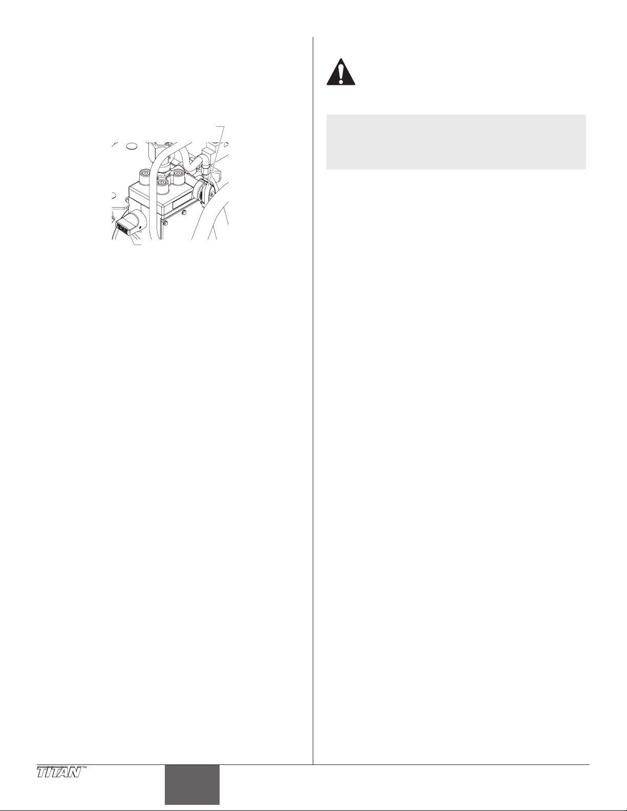
Nettoyage
Soupape de
de la pression
Rangement à long terme
Rangement pour la nuit
Arrêt du moteur
1. Tournez le bouton de réglage de la pression dans le sens
inverse des aiguilles sur le réglage de pression minimale.
2. Placez la soupape de PRIME/SPRAY en position PRIME.
PRIME/SPRAY
Bouton de réglage
3. Placez l’interrupteur ARRÊT/MARCHE (ON/OFF) en position
ARRÊT (OFF).
4. Placez l’interrupteur MARCHE/ARRÊT (ON/OFF) du
compresseur en position ARRÊT (OFF).
5. Attendez quelques secondes puis enclenchez le pistolet dans
le contenant de produit pour libérer la pression de liquide de
la pompe et la pression d’air du compresseur.
6. Verrouillez le pistolet en enclenchant le cran de sûreté (voir le
Guide d’utilisation du pistolet).
7. Débranchez l’appareil.
8. Pour les matériaux en latex uniquement, versez lentement
une demi-tasse sur la surface de la peinture pour l’empêcher
de sécher. Pour d’autres produits, fermez hermétiquement le
contenant en laissant le tuyau de retour dans la peinture.
9. Enveloppez le pistolet pulvérisateur dans un chion humide
et placez-le dans un sac en plastique. Fermez bien le sac
hermétiquement.
10. Placez l’outil dans un endroit sûr à l’abri du soleil pour un
rangement à court terme.
Réutilisation
1. Extrayez le pistolet du sac en plastique.
2. Dans le cas des matériaux au latex, agitez la peinture pour
incorporer l’eau sur la surface. Pour tous les autres produits,
descellez le seau à peinture et agitez la peinture.
3. Procédez comme indiqué dans la section « Peinture » du
présent manuel en fonction du type de pulvérisation à
réaliser.
Ne laissez pas la peinture s’accumuler sur le moteur,
car une telle accumulation risquerait d’entraîner une
surchauffe. Ne laissez pas des solvants inflammables
entrer en contact avec le moteur car ces produits
pourraient s’enflammer.
NOTA : Si vous pulvérisez avec de la peinture au latex,
utilisez de l’eau tiède savonneuse pour le nettoyage.
Si vous utilisez une peinture alkyde ou à l’huile,
utilisez des essences minérales ou un produit diluant
pour peinture.
IMPORTANT: N’utilisez pas d’essences minérales ni de diluant
pour peinture pour les peintures au latex car le mélange se
transformera en une pâte gélatineuse difficile à éliminer.
Nettoyage de la trémie de peinture
Procédez comme suit pour enlever la peinture d’une trémie de
peinture.
1. Verrouillez le pistolet en enclenchant le cran de sûreté (voir le
Guide d’utilisation du pistolet).
2. Tournez le bouton de commande de pression dans le
sens contraire des aiguilles d’une montre jusqu’au réglage
minimum.
3. Tournez le soupape de PRIME/SPRAY sur PRIME.
4. Placez l’interrupteur ON/OFF du moteur sur OFF.
5. Dirigez le tube de retour dans le récipient de peinture
d’origine.
6. Placez l’interrupteur ON/OFF du moteur sur ON.
7. Tournez le bouton de commande de pression sur la moitié
de la pression maximum. De cette manière, la peinture
restante dans la trémie de peinture est aspirée dans la pompe
et remonte dans le tube de retour et dans le récipient de
peinture.
8. Tournez le bouton de commande de pression dans le
sens contraire des aiguilles d’une montre jusqu’au réglage
minimum de pression.
9. Actionnez le pistolet pour supprimer la pression et verrouillez-
le.
10. Retirez le protège-embout et l’embout de pulvérisation et
placez-les dans un récipient d’eau ou de solvant approprié
pour le type de peinture utilisée.
11. Remplissez la trémie de peinture d’eau ou d’un solvant
approprié pour le type de peinture que vous utilisez.
12. Dirigez le tube de retour dans un seau pour résidus.
13. Augmentez la pression à la moitié de la pression maximum.
Laissez l’eau ou le solvant circuler pendant 2-3 minutes pour
évacuer la peinture hors de la pompe, de la trémie et du tube
de retour.
18 © Titan Tool. Tous droits réservés.
Français
Page 19
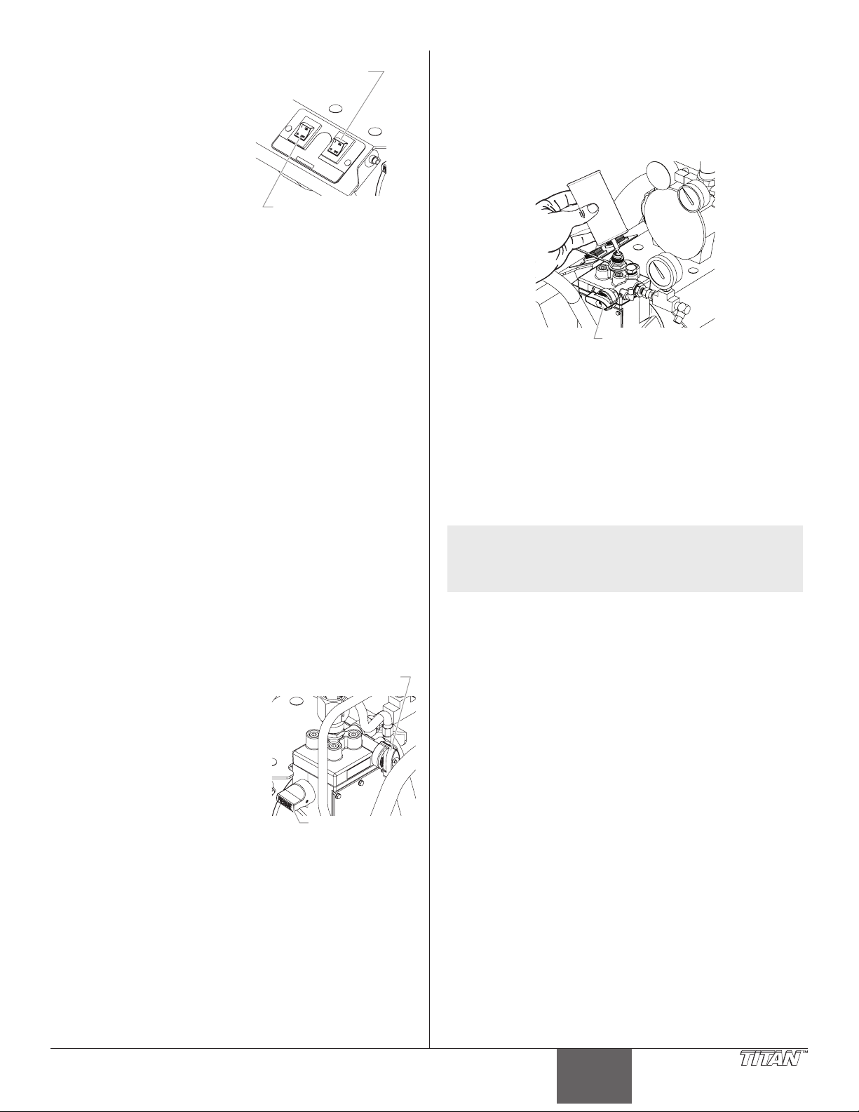
Nettoyage du optional tuyau d’aspiration
T
(ON/OFF) du compresseur
Interrupteur MARCHE/ARRÊT
Soupape de
de la pression
PRIME/SPRAY
1. Tournez le bouton de
réglage de la pression
dans le sens inverse des
aiguilles sur le réglage de
pression minimale.
2. Placez la soupape de PRIME/
SPRAY en position PRIME.
3. Placez l’interrupteur
MARCHE/ARRÊT (ON/OFF)
en position ARRÊT (OFF).
4. Placez l’interrupteur
MARCHE/ARRÊT (ON/OFF)
du compresseur en position ARRÊT (OFF).
5. Attendez quelques secondes puis enclenchez le pistolet dans
le contenant de produit pour libérer la pression de liquide de
la pompe et la pression d’air du compresseur.
6. Verrouillez le pistolet en enclenchant le cran de sûreté (voir le
Guide d’utilisation du pistolet).
7. Enlevez le tuyau d’aspiration du produit et tenez-le au-dessus
d’un seau contenant de l’eau ou un solvant. Laissez le tuyau
de retour dans le contenant de peinture.
IMPORTANT : N’utilisez pas d’essences minérales ou de diluant
pour peinture pour les peintures au latex car le mélange se
transformera en une pâte gélatineuse difficile à éliminer.
8. Placez l’interrupteur MARCHE/ARRÊT (ON/OFF) en position
MARCHE (ON).
9. Placez le bouton de réglage de la pression au réglage
intermédiaire. Vous pourrez ainsi aspirer la peinture restante
dans le tuyau d’aspiration par la pompe, dans le tuyau de
retour puis dans le contenant de peinture.
10. Tournez le bouton de réglage de la pression dans le sens
inverse des aiguilles sur le réglage de pression minimale.
11. Enlevez la tête de pulvérisation et l’embout de protection puis
placez-les dans un bac contenant du solvant approprié.
12. Placez le tuyau d’aspiration monté et le tuyau de retour dans
le seau d’eau ou dans du solvant approprié.
13. Augmentez la pression jusqu’à ce qu’elle corresponde à la
moitié de la pression maximale. Laissez l’eau ou le solvant
circuler pendant 2 à 3 minutes pour faire sortir la peinture de
la pompe, du tuyau d’aspiration et du tuyau de retour.
Nettoyage du tuyau à peinture
1. Tournez le bouton de réglage de la pression dans le sens
inverse des aiguilles sur le réglage de pression minimale.
2. Placez la soupape de PRIME/
SPRAY en position SPRAY.
3. Débloquez le détente de pistolet.
4. Actionnez la gâchette du pistolet
avec la tête de pulvérisation
démontée et placée contre la
partie interne du contenant de
peinture.
5. Tournez le bouton de réglage
de la pression lentement dans le
sens des aiguilles d’une montre
jusqu’à ce que de la peinture
commence à s’écouler dans le
contenant. Dès que l’eau ou le solvant commence à s’écouler
dans le contenant, relâchez la détente.
6. Changez l’eau ou le solvant et continuez à faire circuler le
liquide pendant environ 5 minutes pour nettoyer complètement
le tuyau, la pompe et le pistolet de pulvérisation.
7. Tournez le bouton de réglage de la pression dans le sens
inverse des aiguilles d’une montre jusqu’au réglage minimum.
8. Placez la soupape de prime/spray en position prime.
9. Actionnez le pistolet dans de l’eau ou le conteneur de solvant
pour libérer la pression du liquide de la pompe.
10. Verrouillez le pistolet en enclenchant le cran de sûreté (voir le
Guide d’utilisation du pistolet).
11. Placez l’interrupteur MARCHE/ARRÊT (ON/OFF) en position
ARRÊT (OFF).
© Titan Tool. Tous droits réservés. 19
(ON/OFF) de la pompe
Interrupteur MARCHE/ARRÊ
PRIME/SPRAY
Bouton de réglage
Nettoyage nal
1. Retirez le ensemble de trémie ou l’ensemble d’aspiration de la
soupape d’admission.
2. Nettoyez les letages de la soupape d’admission à l’aide d’un
chion humide.
3. Remplissez la soupape d’entrée d’eau ou d’huile ménagère
légère.
Soupape de
4. Assurez-vous que la soupape de PRIME/SPRAY est bien placée
sur prime et que le bouton de réglage de la pression est
complètement tourné dans le sens inverse des aiguilles d’une
montre, réglé sur la pression la plus basse.
5. Allumez la pompe en plaçant l’interrupteur MARCHE/ARRÊT
(ON/OFF) de la pompe en position MARCHE (ON).
6. Augmentez la pression en faisant tourner le bouton de
réglage de la pression dans le sens des aiguilles d’une montre
d’un demi-tour.
7. Tournez la soupape de PRIME/SPRAY en position spray pour
répartir d’huile.
NOTA : Le nettoyage et le graissage à l’huile de la pompe
8. Tournez le bouton de réglage de la pression dans le sens
9. Placez la soupape de PRIME/SPRAY en position PRIME.
10. Débloquez le pistolet et actionnez-le pour éliminer toute
11. Verrouillez le pistolet en enclenchant le cran de sûreté (voir le
12. Éteignez la pompe en plaçant l’interrupteur MARCHE/ARRÊT
13. Démontez le tuyau à peinture et le tuyau à air du pistolet
14. Essuyez tout l’ensemble, y compris le tuyau et le pistolet,
après utilisation constituent les étapes les plus
importantes pour assurer un bon fonctionnement
après l’entreposage.
inverse des aiguilles d’une montre jusqu’au réglage minimum.
pression qui reste dans le tuyau.
Guide d’utilisation du pistolet).
(ON/OFF) de la pompe en position ARRÊT (OFF).
de pulvérisation à l’aide de deux clés à mâchoires mobiles.
Consultez le manuel de l’utilisateur du pistolet de
pulvérisation pour obtenir plus de détails sur les consignes de
nettoyage du pistolet.
à l’aide d’un chion humide pour éliminer la peinture
accumulée.
Français
English
Page 20
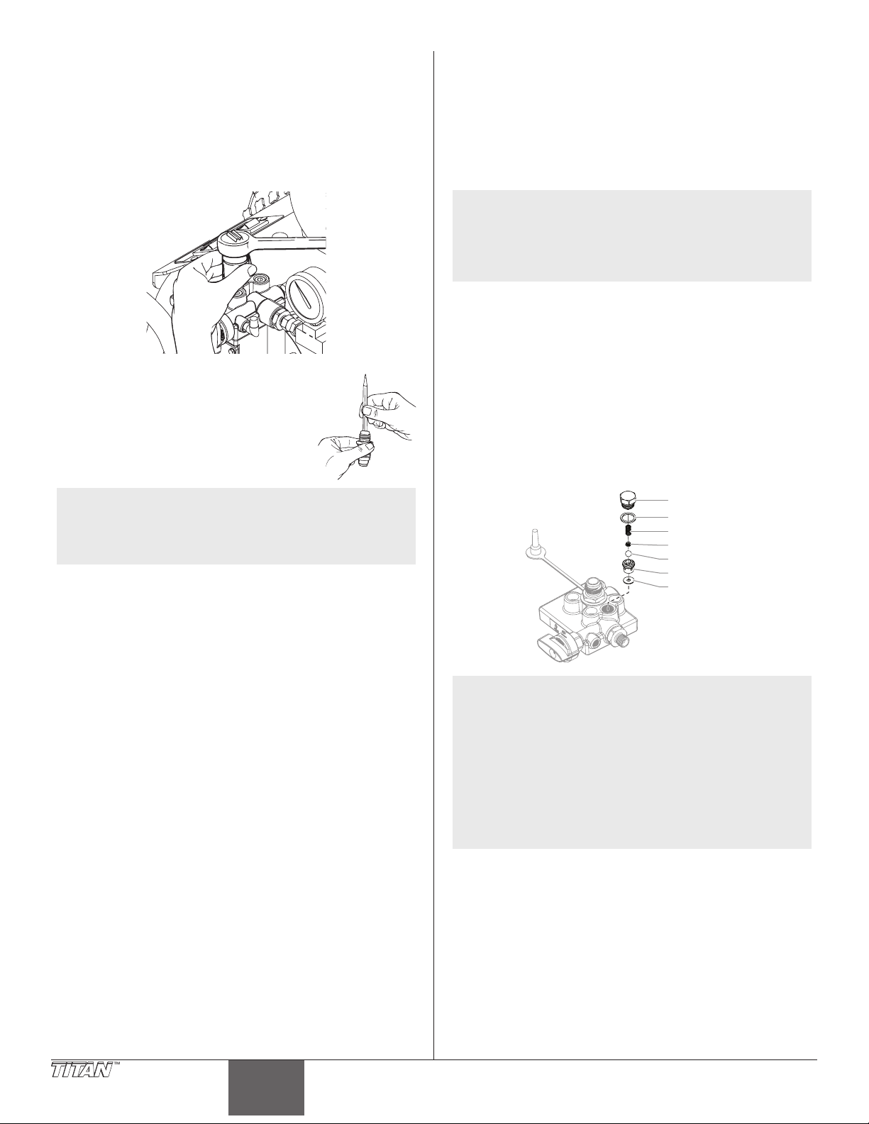
Maintenance
Joint torique
Suivez ces instructions si vous rencontrez des problèmes indiqués
dans la section dépannage.
Démontage et nettoyage de la soupape d’admission
1. Procédez de la façon indiquée dans la procédure de limitation
de la pression; éteignez et débranchez l’appareil.
2. Démontez la soupape d’entrée à l’aide d’une douille de 27
millimètres ou d’une clé polygonale.
Démontage et nettoyage de la soupape de sortie
Il peut s’avérer nécessaire de démonter et de nettoyer la soupape
de sortie ou de remplacer les pièces internes de la soupape qui sont
usées après une utilisation normale.
1. Démontez le écrou de la soupape de sortie à l’aide d’une clé.
2. Démontez et nettoyez la butée à billes et le petit ressort
à l’intérieur de la soupape à l’aide d’un l de fer ou de
petites pinces. Remplacez le ressort s’il est endommagé ou
défectueux.
3. Testez la mobilité de la soupape en
l’enfonçant à partir de l’extrémité ouverte
du carter de la soupape à l’aide d’un
tournevis ou de la gomme à eacer de
l’extrémité d’un crayon. Elle doit bouger
d’environ 1,6 mm (1/16 po). Si elle ne
bouge pas, vous devez la nettoyer ou la
remplacer.
NOTA : La soupape d’admission doit être huilée après
chaque utilisation. Cette précaution vous permettra
de réduire ou d’éliminer les problèmes d’amorçage
lors de la prochaine utilisation de l’appareil, tout en
allongeant la durée de vie utile de la soupape.
4. Nettoyez soigneusement la soupape à l’eau ou avec un
solvant approprié. Utilisez une petite brosse.
5. Si la soupape a bien été nettoyée et que de l’eau s’écoule
de sa partie inférieure, elle est usée et doit être remplacée.
Une soupape remplie d’eau, bien appuyée sur son siège et
maintenue en position verticale ne fuit pas.
6. Installez une nouvelle soupape ou une soupape nettoyée dans
le corps de la pompe puis remplissez-la d’huile légère ou de
solvant.
NOTA : Ce ressort est fabriqué de manière à avoir une
tension spécique. Ne l’étirez pas. Ne le remplacez
pas par une pièce de rechange non homologuée.
Consultez le schéma de montage des pièces de la
pompe de peinture pour connaître la référence de la
pièce de rechange.
3. Retirez le siège de soupape et l’ensemble à billes.
4. Nettoyez soigneusement toutes les pièces. Si la bille ou le
siège semble usé(e), remplacez-les par des nouvelles pièces.
Cette bille au carbure doit être parfaitement hermétique sur
son siège pour que la soupape fonctionne correctement.
5. Couvrez toutes les pièces d’une ne couche d’huile légère
avant de remonter l’ensemble.
6. Placez la bille de la soupape.
7. Insérez le protecteur et le ressort puis replacez le corps de la
soupape. Assurez-vous que le joint torique est bien en place et
que la languette du capuchon rentre bien dans le ressort.
8. Serrez le corps de la soupape à l’aide d’une clé. Ne la serrez
pas trop.
Écrou
Ressort
Butée à bille
Bille
Siège
Joint
NOTA : L’usure de la bille est pratiquement impossible à
détecter visuellement. Pour voir si une soupape de
sortie est usée, tournez le bouton de réglage de la
pression dans le sens des aiguilles d’une montre
sur le réglage maximum et faites couler de l’eau
seulement dans la pompe pendant environ 10 à 15
minutes sans enclencher le pistolet.
Si la soupape est défectueuse, le capuchon
d’extrémité peut devenir très chaud au toucher. Si
la soupape fonctionne correctement, il reste à peu
près à la même température que l’eau qui circule à
l’intérieur.
20 © Titan Tool. Tous droits réservés.
Français
Page 21

Dépannage
Problème
A. Le pulvérisateur ne démarre
pas.
B. La pompe démarre, mais
n’aspire pas la peinture lorsque
la soupape de PRIME/SPRAY est
placée sur prime.
C. La pompe aspire de la peinture,
mais la pression retombe
lorsque le pistolet est actionné.
D. Traînées de peinture.
E. Le dispositif de protection
thermique s’est déclenché et a
éteint la pompe.
F. Le compresseur ne démarre pas.
G. Le compresseur démarre, mais il
n’y a pas assez d’air.
Cause
1. L’appareil n’est pas branché.
2. L’interrupteur MARCHE/ARRÊT (ON/OFF) est
placé sur ARRÊT (OFF).
3. Un fusible a grillé dans l’appareil.
4. La tension provenant de la prise murale est
faible ou inexistante.
5. L’appareil a été éteint pendant qu’il était
toujours sous pression.
6. La rallonge électrique est endommagée ou sa
capacité est trop faible.
7. Le dispositif de protection thermique de
l’appareil s’est déclenché.
8. Il y a un problème avec le moteur.
1. La pompe ne s’amorce pas correctement ou
l’amorçage se perd.
2. Le contenant de peinture est vide ou le tuyau
d’aspiration n’est pas totalement plongé dans
la peinture.
3. Le ltre de l’ensemble d’aspiration est colmaté.
4. Le tuyau d’aspiration est mal xé sur la
soupape d’admission.
5. La soupape d’admission est bloquée.
6. La soupape de sortie est bloquée.
7. La soupape de PRIME/SPRAY est bloquée.
8. La soupape d’admission est usée ou
endommagée.
9. Il y a un problème avec le diaphragme.
10. Le niveau d’huile hydraulique est trop bas ou
le réservoir est vide.
1. La tête de pulvérisation est usée.
2. Le ltre de l’ensemble d’aspiration est colmaté.
3. Le ltre du pistolet ou de la tête de
pulvérisation est colmaté.
4. La peinture est trop lourde ou trop épaisse.
5. La soupape de sortie est sale ou usée.
6. La soupape d’admission est endommagée ou
usée.
1. La pression de liquide est trop basse.
2. La pression d’air est trop basse.
3. Le pistolet, la tête de pulvérisation ou le ltre
de l’ensemble d’aspiration est bloqué.
4. Le tuyau d’aspiration est mal xé sur la
soupape d’admission.
5. La tête de pulvérisation est usée.
6. La peinture est trop épaisse.
1. Le moteur a surchaué.
2. La rallonge électrique est trop longue ou son
calibre est trop petit.
3. De la peinture s’est accumulée sur le moteur.
4. Le moteur a été mis en marche pendant que
l’appareil était sous pression.
5. L’appareil a été laissé en plein soleil.
1. L’interrupteur MARCHE/ARRÊT (ON/OFF) du
compresseur est en position ARRÊT (OFF).
2. L’interrupteur MARCHE/ARRÊT (ON/OFF) du
compresseur est endommagé.
3. Problème de compresseur.
4. L’orice de décompression sous le régulateur
d’air est bloqué.
1. Le régulateur d’air est réglé trop faiblement.
2. La peinture est trop épaisse.
3. Soupape d’air fermée sur le pistolet.
4. Mauvaise limitation de pression.
Solution
1. Branchez l’appareil.
2. Placez l’interrupteur MARCHE/ARRÊT (ON/OFF) en
position MARCHE (ON).
3. Remplacez le fusible grillé par une pièce de rechange
adaptée.
4. Testez correctement la tension d’alimentation électrique.
5. Placez le bouton de PRIME/SPRAY en position prime.
6. Rempl
7. Laissez le moteur refroidir et placez l’appareil dans un
8. Faites réparer l’appareil dans un centre d’entretien agréé
1. Essayez d’amorcer de nouveau la pompe.
2. Plongez le tuyau d’aspiration dans la peinture.
3. Nettoyez le ltre de l’ensemble d’aspiration.
4. Nettoyez le raccord du tuyau et serrez-le fermement.
5. Nettoyez la soupape d’admission.
6. Nettoyez la soupape de sortie et remplacez toutes les
7. Faites réparer dans un centre d’entretien agréé par Titan.
8. Remplacez la soupape d’admission.
9. Faites réparer dans un centre d’entretien agréé par Titan.
10. Faites réparer dans un centre d’entretien agréé par Titan.
1. Remplacez la tête de pulvérisation par une tête neuve.
2. Nettoyez le ltre de l’ensemble d’aspiration.
3. Nettoyez ou remplacez le ltre. Ayez toujours des ltres
4. Diluez ou tamisez la peinture.
5. Nettoyez ou remplacez la soupape de sortie.
6. Remplacez la soupape d’admission.
1. Augmentez la pression du liquide.
2. Augmentez le réglage du régulateur d’air.
3. Nettoyez les ltres.
4. Serrez le raccord de tuyau d’aspiration.
5. Remplacez la tête de pulvérisation.
6. Diluez la peinture.
1. Laissez-la refroidir pendant 30 minutes.
2. Laissez-la refroidir pendant 30 minutes et remplacez la
3. Éliminez les éclaboussures de peinture présentes sur le
4. Redémarrez l’appareil en mode AMORÇAGE.
5. Placez l’appareil à l’ombre.
1. Placez l’interrupteur MARCHE/ARRÊT (ON/OFF) du
2. Faites réparer dans un centre d’entretien agréé par Titan.
3. Faites réparer dans un centre d’entretien agréé par Titan.
4. Nettoyez l’orice de décharge.
1. Augmentez le réglage du régulateur d’air.
2. Diluez la peinture.
3. Ouvrez la soupape d’air du pistolet. Consultez le manuel
4. Installez une soupape de décharge neuve.
acez la rallonge.
endroit plus frais.
par Titan.
pièces usées.
de rechange à votre disposition.
rallonge par une rallonge plus courte ou d’un plus gros
calibre.
moteur.
compresseur en position MARCHE (ON).
d’utilisation du pistolet.
© Titan Tool. Tous droits réservés. 21
Français
English
Page 22
Información de seguridad importante
Receptáculo conectado a tierra
Tapa de la caja de receptáculo conectada a tierra
Lea toda la información de seguridad antes de
operar el equipo. Guarde estas insturcciones.
Indica una situación peligrosa que, de no evitarse,
puede causar la muerte o lesiones graves.
Para reducir los riesgos de incendios, explosiones,
descargas eléctricas o lesiones a las personas, lea y
entienda todas las instrucciones incluidas en este
manual. Familiarícese con los controles y el uso
adecuado del equipo.
Instrucciones para la conexión a tierra
Este producto debe conectarse a tierra. En caso de un cortocircuito
eléctrico, la conexión a tierra reduce el riesgo de choque eléctrico
al aportar un alambre de escape para la corriente eléctrica. Este
producto está equipado con un cable que tiene alambre a tierra con
un enchufe a tierra adecuado. Debe usarse el enchufe para conectar a
un receptáculo que esté debidamente instalado y conectado a tierra
en conformidad con los códigos y las ordenanzas locales.
ADVERTENCIA - La instalación incorrecta del enchufe a
tierra puede ocasionar un riesgo de choque eléctrico.
Si es necesario reparar o cambiar el cable o el enchufe, no conecte
el cable verde a tierra a ninguno de las terminales de espiga plana.
El cable con aislamiento de color verde por fuera con o sin rayas
amarillas es el alambre a tierra y debe conectarse a la espiga a tierra.
Consulte a un electricista o técnico de servicio capacitado si las
instrucciones para la conexión a tierra no se entienden claramente
o si tiene dudas en cuanto a que el producto esté debidamente
conectado a tierra. No modique el enchufe que se incluye. Si
el enchufe no encaja en el receptáculo, pida a un electricistas
capacitado que instale un receptáculo adecuado.
Este producto es para utilizarse en un circuito de 120 voltios
nominales y tiene un enchufe a tierra que tiene un aspecto similar al
ilustrado más abajo. Asegúrese que el producto esté conectado a un
tomacorriente que tenga la misma conguración que el enchufe. No
deben utilizarse adaptadores para este producto.
NOTA: No se recomienda usar una extensión de más de
100 pies. Use una longitud mayor de manguera de
pintura, no una extensión más larga. Una extensión
más corta asegurará que haya la energía eléctrica
máxima para tener un funcionamiento apropiado.
ADVERTENCIA: EXPLOSIÓN O INCENDIO
Los vapores de solventes y pinturas pueden explotar o
inamarse. Pueden producirse daños materiales, lesiones
graves o ambos.
PREVENCIÓN:
• No pulverice materiales inamables ni combustibles cerca
de llamas desnudas, pilotos o fuentes de ignición como
objetos calientes, cigarrillos, motores, equipos eléctricos
o electrodomésticos. Evite producir chispas al conectar y
desconectar los cables de alimentación.
• Tenga muchísmo cuidado al usar materiales cuyo punto de
ignición sea inferior a 38 ºC (100 °F). El punto de inamación
22 © Titan Tool. Todos los derechos reservados.
Pata a tierra
es la temperatura a la que un uido puede producir vapor
suciente como para incendiarse.
• La pintura o disolvente que pase por el equipo puede producir
electricidad estática. La electricidad estática supone un riesgo
de incendio o explosión en presencia de emanaciones de
pintura o disolvente. Todas las piezas del sistema pulverizador,
incluyendo la bomba, el conjunto de mangueras, la pistola
pulverizadora y los objetos dentro y alrededor de la zona de
pulverización se conectarán a tierra para protegerlos frente
a descargas estáticas y chispas. Utilice solamente mangueras
para pulverizadores de pintura airless (sin aire) de alta
presión conductoras o con toma a tierra especicadas por el
fabricante.
• Compruebe que todos los recipientes y sistemas de recogida
están conectados a tierra para evitar descargas eléctricas.
• Conecte a una salida con toma a tierra y utilice cables
alargadores puestos a tierra. No utilice un adaptador de 3 a 2.
• No utilice pintura o disolvente que contenga hidrocarburos
halogenados, como cloro, fungicida blanqueador, cloruro de
metileno y tricloroetano. No son compatibles con el aluminio.
Póngase en contacto con el proveedor del material para
conocer su compatibilidad con el aluminio.
• Mantenga la zona de pulverización bien ventilada. Asegúrese
de que circula aire fresco por la zona para evitar que se
acumulen vapores inamables en el aire de la zona de
pulverización. Ponga el conjunto de la bomba en una zona
bien ventilada. No pulverice el conjunto de la bomba.
• No fume en la zona de pulverización.
• No encienda interruptores de luces, motores ni productos
similares que puedan producir chispas en la zona de
pulverización.
• Mantenga la zona limpia y despejada de botes de pintura y
disolventes, trapos y otros materiales inamables.
• Infórmese del contenido de la pintura y de los disolventes
que pulverice. Lea las hojas de datos sobre seguridad de los
materiales (MSDS) y las etiquetas en los botes de pintura y
disolvente. Siga las instrucciones de seguridad del fabricante
de la pintura y del disolvente.
• Coloque la bomba al menos a 7,62 metros (25 pies) del objeto
que se va a pulverizar en una zona bien ventilada (añada más
manguera si fuera necesario). Los vapores inamables suelen
ser más pesados que el aire. La zona del suelo debe estar muy
bien ventilada. La bomba contiene piezas que forman arcos
que producen chispas y pueden inamar los vapores.
• El plástico puede producir chispas estáticas. Nunca utilice
plástico para cercar la zona de pulverización. No utilice
cortinas de plástico mientras pulveriza material inamable.
• Deberá contar con equipos extintores de incendios que
funcionen correctamente.
ADVERTENCIA: LESIÓN POR INYECCIÓN
El ujo de pintura a alta presión que produce este
equipo puede perforar la piel y los tejidos subyacentes,
ocasionando lesiones graves y posible amputación.
CONSULTE A UN MÉDICO INMEDIATAMENTE.
PREVENCIÓN:
• No apunte con la pistola ni pulverice sobre ninguna persona ni
animal.
• Mantenga las manos y el resto del cuerpo lejos de la descarga.
Por ejemplo, no trate de detener fugas con ninguna parte de
su cuerpo.
• NUNCA ponga la mano frente a la pistola. Los guantes no
protegen contra una lesión por inyección.
• SIEMPRE mantenga la protección de la boquilla en su sitio al
rociar. La protección de la boquilla sirve principalmente de
dispositivo de advertencia.
Español
Page 23

Información de seguridad importante
• Utilice solamente la boquilla especicada por el fabricante.
• Tenga cuidado al limpiar y cambiar las boquillas. Si la boquilla
se atasca durante la pulverización, ponga SIEMPRE el seguro
del gatillo de la pistola, apague la bomba y libere toda la
presión antes de reparar, limpiar el protector o la boquilla
o cambiar la boquilla. La presión no se libera apagando el
motor. Para liberar la presión hay que poner la manija de la
válvula PRIME/SPRAY en PRIME. Consulte el Procedimiento de
Alivio de Presión que se describe en el manual de la bomba.
• No deje el aparato con corriente ni con presión cuando nadie
esté pendiente de ella. Cuando no utilice el aparato, apáguelo
y libere la presión siguiendo las instrucciones del fabricante.
• La pulverización a alta presión puede inyectar toxinas en el
cuerpo y producir daños graves en el mismo. En caso de que
esto ocurra, visite a un médico inmediatamente.
• Compruebe las mangueras y las piezas en busca de daños;
una fuga puede inyectar material en la piel. Inspeccione la
manguera antes de cada uso. Sustituya las mangueras o las
piezas dañadas. Por razones de funcionamiento, seguridad
y duración, emplear únicamente mangueras de alta presión
originales de TITAN.
• Este sistema es capaz de producir 2800 PSI / 193 Bar. Utilice
solamente piezas de repuesto o accesorios especicados por
el fabricante y con una capacidad nominal de 2800 PSI como
mínimo. Entre ellos se incluyen boquillas pulverizadoras,
protectores para las boquillas, pistolas, alargadores, racores y
mangueras.
• Ponga siempre el seguro del gatillo cuando no esté
pulverizando. Verique que el seguro del gatillo funciona
correctamente.
• Antes de utilizar el aparato, verique que todas las conexiones
son seguras.
• Aprenda a detener el aparato y a liberar la presión
rápidamente. Familiarícese a conciencia con los controles. La
presión no se libera apagando el motor. Para liberar la presión
hay que poner la manija de la válvula PRIME/SPRAY en
PRIME. Consulte el Procedimiento de Alivio de Presión que se
describe en el manual de la bomba.
• Quite siempre la boquilla pulverizadora antes de enjuagar o
limpiar el sistema.
NOTA PARA EL MÉDICO: La inyección a través de la piel es una
lesión traumática. Es importante tratar la lesión tan pronto sea
posible. NO retrase el tratamiento para investigar la toxicidad.
La toxicidad es un factor a considerar con ciertos revestimientos
inyectados directamente en la corriente sanguínea. Puede ser
aconsejable consultar con un cirujano plástico o un cirujano
especialista en reconstrucción de las manos.
ADVERTENCIA: VAPORES PELIGROSOS
Las pinturas, solventes, insecticidas y demás materiales
pueden ser nocivos si se inhalan o toman contacto con
el cuerpo. Los vapores pueden causar náuseas graves,
desmayos o envenamiento.
PREVENCIÓN:
• Use un respirador o mascarilla si pueden inhalarse los vapores.
Lea todas las instrucciones suministradas con la mascarilla
para revisar que brinde la protección necesaria.
• Use lentes protectores.
• Use ropa protectora según lo indique el fabricante del
revestimiento.
ADVERTENCIA: GENERAL
Puede causar daños materiales o lesiones graves.
PREVENCIÓN:
• Cuando pinte, lleve siempre guantes, protección para los ojos,
ropa y un respirador o máscara adecuados.
• Nunca utilice el aparato ni pulverice cerca de niños. Mantenga
el equipo alejado de los niños en todo momento.
• No se estire demasiado ni se apoye sobre un soporte inestable.
Mantenga los pies bien apoyados y el equilibrio en todo
momento.
• No se distraiga y tenga cuidado con lo que hace.
• No utilice el aparato si está fatigado o se encuentra bajo la
inuencia del alcohol o de las drogas.
• No retuerza ni doble la manguera en exceso. En la manguera
airless pueden aparecer fugas a causa del desgaste, de
retorcimientos o de un mal uso. Una fuga puede inyectar
material en la piel.
• No exponga la manguera a temperaturas o presiones que
superen las especicadas por el fabricante.
• No utilice la manguera como elemento de fuerza para tirar del
equipo o levantarlo.
• Utilice la presión más baja posible para enjuagar el equipo.
• Cumpla todos los reglamentos locales, estatales y nacionales
pertinentes relativos a ventilación, prevención de incendios y
funcionamiento.
• Las normas sobre seguridad del gobierno de los Estados
Unidos se han adoptado al amparo de la Ley de salud y
seguridad ocupacional (OSHA). Deben consultarse tres
normas, particularmente la sección 1910 de las Normas
generales y la sección 1926 de las Normas sobre construcción.
• Cada vez que vaya a utilizar el equipo, compruebe antes todas
las mangueras en busca de cortes, fugas, abrasión o bultos en
la cubierta. Compruebe el movimiento de los acoplamientos
y si están dañados. Sustituya inmediatamente una manguera
si descubre alguna de estas anomalías. No repare nunca
una manguera de pintura. Sustitúyala por una manguera
conductora a alta presión.
• No pulverice al aire libre si hace viento.
• Desenchufe siempre el cable antes de trabajar en el equipo.
IMPORTANTE: La bomba del diafragma se proporciona con
un reinicio automático de protección térmica. Si ocurre una
sobrecarga, el reinicio automático de protección térmica
desconecta el motor del suministro de energía eléctrica.
• Cuando el protector se reinicie automáticamente, el motor
volverá a arrancar sin advertencia.
• Desconecte siempre el motor del suministro de energía
eléctrica antes de trabajar en el equipo.
• Cuando el reinicio automático de protección térmica
desconecte el motor del suministro de energía eléctrica,
libere la presión girando la válvula PRIME/SPRAY (CEBAR/
PULVERIZAR) a la posición PRIME.
• Gire el interruptor ON/OFF (ENCENDIDO/ APAGADO) de la
bomba a la posición OFF.
NOTA: La causa de la sobrecarga se debe corregir antes de
volver a arrancar. Consulte la sección de Solución
de problemas.
© Titan Tool. Todos los derechos reservados. 23
Español
Page 24
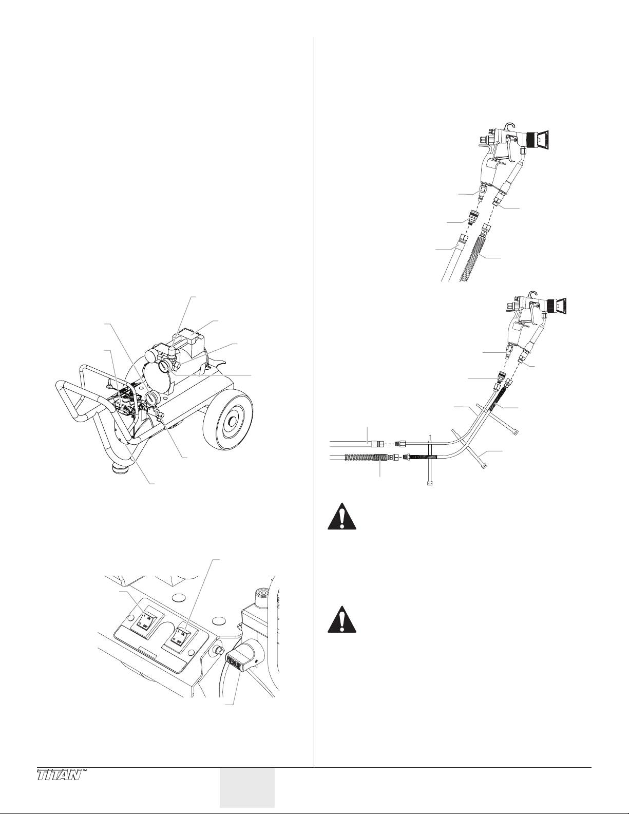
Table of Contents
Manómetro del
Bomba de diafragma
o
Regulador de la
del compresor
Válvula de control de presión
Interruptor
de admisión
C
a
Precauciones de seguridad ......................................................22-23
Instrucciones de conexión a tierra .......................................................23
Descripción general ...................................................................... 24
Instalación ...................................................................................... 24
Operación ....................................................................................... 25
Cebado de la bomba .................................................................................25
Pintura ............................................................................................................26
Procedimiento para el alivio de la presión ........................................27
Técnica de pulverización .............................................................. 27
Limpieza ......................................................................................... 28
Almacenamiento durante la noche .....................................................28
Almacenamiento a largo plazo ..............................................................28
Mantenimiento .............................................................................. 30
Retiro y limpieza de la válvula de admisión ......................................30
Retiro y limpieza de la válvula de salida .............................................30
Solución de problemas ................................................................. 31
Lista de piezas ................................................................................ 32
Garantía limitada ........................................................................... 40
Descripción general
Este sistema de pulverización de no acabado es lo sucientemente
versátil como para usarse en trabajos de acabado a bajas presiones
al igual que en pulverizaciones sin aire a altas presiones. El sistema
incluye una bomba de diafragma de pintura y un compresor de aire
que funcionan juntos a n de brindar esta versatilidad.
presión de aire
Compresor de aire
material
Válvula
PRIME/SPRAY
Adaptador
de salida
del aire
Manómetr
de aire
4. Con una llave, conecte al adaptador de salida de material,
presente en la bomba, un mínimo de 50’ (15,2 m) de
manguera de nylon de 1/4” para pulverizaciones sin aire.
Apriete rmemente.
5. Conecte la manguera de pulverización al adaptador de
admisión de material en la pistola pulverizadora. Usando
dos llaves (una en la pistola y la otra en la manguera), apriete
rmemente.
onguración estándar
de las mangueras:
Adaptador de
admisión de aire
Adaptador
Manguera
de aire
Opcional látigo
con mangueras:
Adaptador de
admisión de aire
Adaptador
Adaptador
de material
Manguera
de material
Adaptador
de admisión
de material
Instalación
Siga este procedimiento para instalar el sistema de pulverización.
1. Asegúrese de que el interruptor ON/OFF de la bomba y el del
2. Asegúrese de que la válvula de control de presión se gire
3.
24 © Titan Tool. Todos los derechos reservados.
Adaptador de salida
del material
compresor se encuentren en la posición OFF.
de ON/OFF
de la bomba
Interruptor
de ON/OFF
completamente en contra del sentido de las agujas del reloj,
hasta su ajuste de presión mínimo.
Bloquee la pistola girando el seguro del gatillo hasta que quede en
posición de bloqueado (consulte el manual de la pistola).
Español
Látigo manguera
Manguera de aire
Manguera de material
Asegúrese de que todas las mangueras sin aire y las
pistolas pulverizadoras posean una conexión eléctrica
a tierra calculadas para una presión de fluidos de al
menos 2800 PSI (19 MPa).
6. Conecte la manguera de aire al adaptadorde salida del aire
presente en el compresor. Apriete rmemente.
7. Conecte la adaptador del manguera de aire al adaptador
de admisión de aire en la pistola pulverizadora. Conecte la
manguera de aire al adaptador. Apriete rmemente.
Cambiar las conexiones de las mangueras puede
ocasionar lesiones graves. Asegúrese de que la
manguera de pulverización sin aire esté conectada
desde la bomba de diafragma al adaptador de
admisión de material presente en la pistola. Asimismo,
asegúrese de que la manguera de aire esté conectada
desde el compresor al adaptador de admisión de aire
de la pistola.
8. Asegúrese de que el servicio eléctrico sea de un mínimo de
120V, 15 amp.
9. Enchufe el cable de alimentación a una toma conectada
adecuadamente a tierra a una distancia de al menos 25’ (7,6
m) del área de pulverización.
IMPORTANTE: Use siempre un cable de extensión trifilar de un
calibre de 12 con un enchufe conectado a tierra. Nunca retire el
tercer terminal ni use un adaptador.
de aire
Látigo manguer
de material
Correas
Page 25
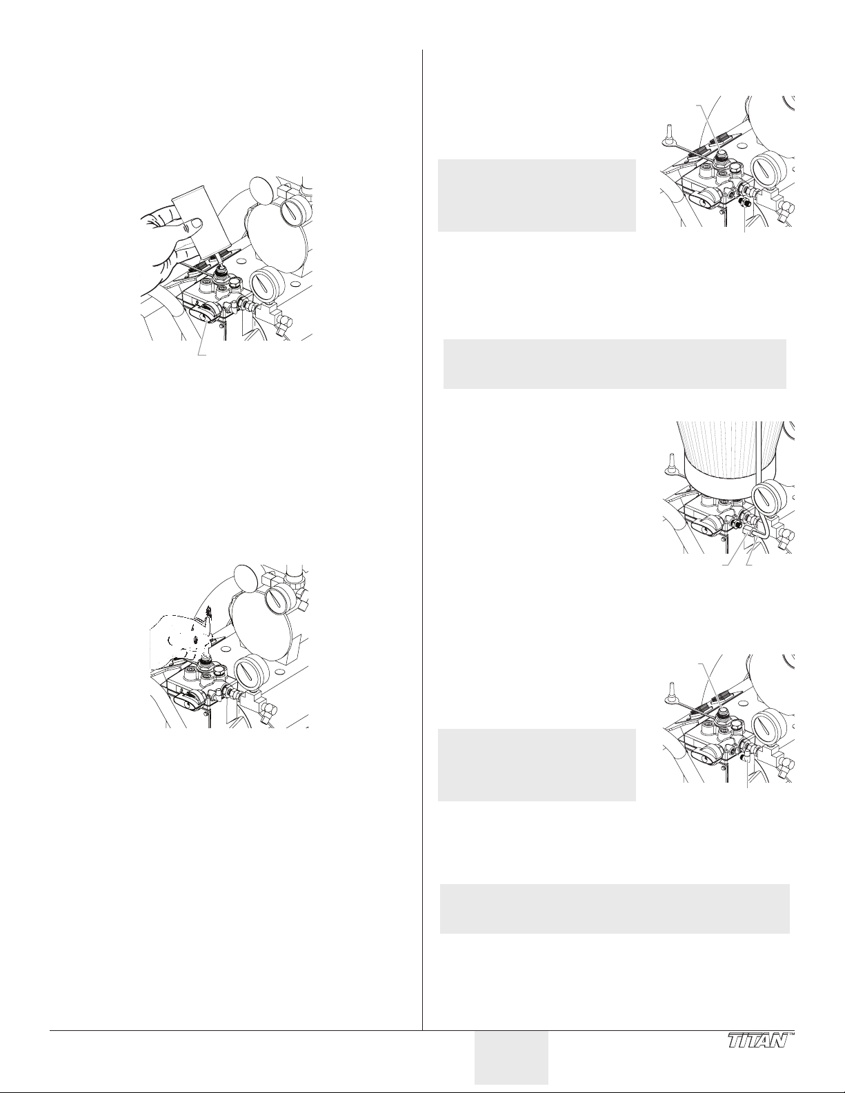
Operación
Válvula PRIME/SPRAY
de retorno
Válvula
de entrada
Tubo de
Válvula
Siga los siguientes procedimientos para poder operar el sistema de
pulverización.
Cebado de la bomba
Preparación para cebar
1. Llene la válvula de admisión con agua o con un aceite
domestico ligero.
Montaje de la tolva de pintura
Use el procedimiento siguiente para montar la tolva de pintura y jar
el tubo de retorno a una unidad de tolva.
1. Atornille el conector del tubo
de retorno en el oricio del
tubo de retorno en el lado de la
bomba.
NOTA: No lo apriete demasiado.
2. Alinee la parte inferior de la
3. Gire la tolva de pintura en el sentido de las agujas del reloj
Apriételo sólo con la
mano. Algunas roscas
seguirán visibles aunque
se aprieten del todo.
Adaptador del tubo
tolva de pintura con la válvula
de entrada roscada en el bloque de la bomba de pintura.
para enroscarla en la válvula de entrada. Continúe girando
la tolva de pintura hasta que quede jada en la válvula de
entrada.
2. Asegúrese de que la válvula PRIME/SPRAY esté ajustada en
PRIME y de que la válvula de control de presión esté girada en
contra del sentido de las agujas del reloj a su menor ajuste de
presión.
3. Encienda la bomba al mover el interruptor ON/OFF
(ENCENDIDO/APAGADO) de la bomba a la posición ON.
4. Aumente la presión al girar la válvula de control de presión
1/2 vuelta en el sentido de las agujas del reloj.
5. Fuerce la apertura y cierre de la válvula de admisión
presionándola con un destornillador o con el extremo para
borrar de un lápiz. Debería subir y bajar cerca de 1/16 de
pulgada (1,58 mm). Continúe hasta que el agua o el aceite
sea aspirado hacia la bomba. Esto humedecerá las partes en
movimiento y soltará todos los residuos de pintura antigua.
6. Ponga la palma de su mano sobre la entrada: gire la válvula
de control de presión en el sentido de las agujas del reloj
al ajuste máximo. Debe sentir la aspiración que proviene
de la válvula de admisión. Si esto no ocurre, consulte el
procedimiento de “Retiro y limpieza de la válvula de salida”,
presente en la sección Mantenimiento.
7. Gire la válvula de control de presión en contra del sentido de
las agujas del reloj al ajuste de presión mínima.
8. Gire el interruptor ON/OFF de la bomba a la posición OFF.
NOTA: Asegúrese de que las roscas están rectas y de que la
4. Coloque el ltro en la parte inferior de la tolva de pintura y
5. Asegúrese de que el interruptor de
6. Coloque el extremo recto del tubo
7. Enrosque la tuerca del tubo de
8. Coloque el extremo del gancho del
tolva gira libremente sobre la válvula de entrada.
No cruce las roscas.
encájelo en su posición.
encendido/apagado del motor está
en la posición OFF (apagado).
de retorno en el racor de dicho
tubo.
retorno en el racor de dicho tubo y
apriete hasta que quede bien jado.
tubo de retorno en el oricio de la
tapa de la tolva de pintura.
Tuerca
retorno
Montaje del conjunto de aspiración opciónal
Use el siguiente procedimiento para acoplar el conjunto de
aspiración a su unidad.
1. Retire el conector del tubo de
retorno de tolva. Atornille el
adaptador del tubo de retorno
en el oricio del tubo de
retorno en el lado de la bomba.
NOTA: No lo apriete demasiado.
Apriételo sólo con la
mano. Algunas roscas
seguirán visibles aunque
se aprieten del todo.
2. Alinee la tuerca del conjunto de
aspiración con la válvula de entrada roscada en el bloque de la
bomba de pintura.
3. Rosque la tuerca de la manguera de aspiración a la válvula de
admisión presente en la bomba.
de entrada
Adaptador de
tubo de retorno
© Titan Tool. Todos los derechos reservados. 25
NOTA: Asegúrese de que las roscas están bien rectas y de que
la tuerca gira libremente sobre la válvula de entrada.
No cruce las roscas.
4. Rosque la manguera de retorno en el adaptador de la
manguera de retorno presente en la bomba.
Español
Page 26
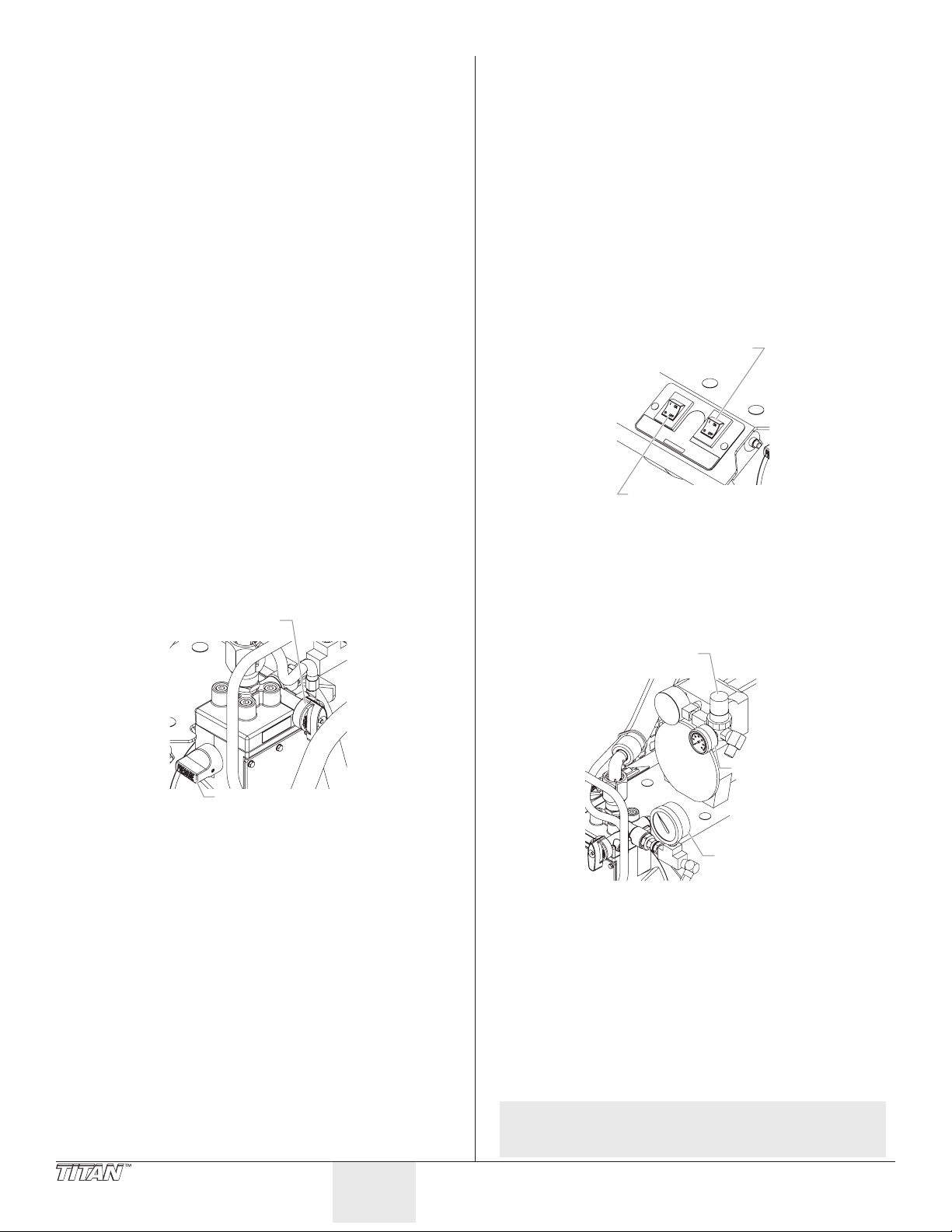
Cebado con conjunto de tolva
Válvula
de presión
del compresor
Interruptor de ON/OFF
Regulador de la
o
1. Gire el mando de control de presión en el sentido contrario a
las agujas del reloj hasta la posición de presión mínima.
2. Retire la tapa de la válvula de pintura y llene la tolva de
pintura o coloque el conjunto de aspiración en un cubo con
material.
3. Coloque la válvula PRIME/SPRAY en la posición PRIME.
4. Coloque el interruptor encendido/apagado del motor en la
posición ON.
5. Gire el mando de control de presión en el sentido de las
agujas del reloj hasta la posición entre la presión media y
máxima. Deje que la unidad se cebe durante 1 ó 2 minutos
una vez que el material empiece a uir por el tubo de retorno.
IMPORTANTE: Reduzca siempre la presión a cero antes de
cambiar la posición de la válvula PRIME/SPRAY. Si no lo hace,
podrían producirse daños en el diafragma de la bomba de
pintura.
IMPORTANTE: Si el mando de control de presión se pone a cero y
la válvula PRIME/SPRAY (cebar/pulverizar) no está en la posición
SPRAY mientras el pulverizador está funcionando, habrá una
gran presión en la manguera y la pistola pulverizadora hasta que
se ponga la válvula PRIME/SPRAY en la posición PRIME o hasta
que se apriete el gatillo de la pistola para liberar la presión.
Cebado con conjunto de aspiración
1. Ubique el conjunto de aspiración en el recipiente de pintura.
2. Gire la válvula de control de presión en contra del sentido de
las agujas del reloj al ajuste de presión mínima.
IMPORTANTE: Reduzca siempre la presión a cero al
desencadenar la pistola antes de cambiar la posición de la
válvula PRIME/SPRAY. No hacerlo puede causar daños al
diafragma de la bomba de pintura.
3. Gire la válvula PRIME/SPRAY a PRIME.
PRIME/SPRAY
Pintura
El sistema de pulverización AirCoat tiene dos modos de pintura
diferentes. El modo AirCoat se usa para trabajos de acabado con
materiales de baja o media viscosidad (aceites, tinturas, lacas, etc...).
El modo sin aire se usa para pinturas en general con materiales de
alta viscosidad (látex).
Pintura en modo AirCoat
Use el modo AirCoat para trabajos de acabado a bajas presiones
(recomendó la presión de la bomba de hasta 1000 PSI).
1. Asegúrese de que la manguera de pulverización sin aire no
tenga torceduras y de que esté lejos de objetos cortantes.
2. Gire la válvula de control de presión en contra del sentido de
las agujas del reloj al ajuste mínimo.
3. Gire el regulador de la presión de aire del compresor en contra
del sentido de las agujas del reloj al ajuste mínimo.
4. Mueva el interruptor ON/OFF del compresor a la posición ON.
5. Mueva el interruptor ON/OFF de la bomba a la posición ON.
de la bomba
Interruptor de ON/OFF
6. Gire la válvula PRIME/SPRAY a SPRAY.
7. Gire la válvula de control de presión en el sentido de las
agujas del reloj hasta que en el manómetro del material se
lea 400 PSI. La manguera de pintura se debe endurecer en la
medida que pase pintura a través de ella.
8. Gire el regulador de la presión de aire en el sentido de las
agujas del reloj hasta que en el manómetro del material se lea
20 PSI.
4. Mueva el interruptor ON/OFF de la bomba a la posición ON.
5. Gire la válvula de control de presión en el sentido de las
agujas de reloj hasta que se encuentre entre la presión media
y la total. Deje cebar la unidad de 1 a 2 minutos luego de que
la pintura comience a uir a través de la manguera de retorno
hasta que ya no haya burbujas.
6. Gire la válvula de control de presión en contra del sentido de
las agujas del reloj al ajuste de presión mínima.
7. Mueva el interruptor ON/OFF de la bomba a la posición OFF.
IMPORTANTE: Si la válvula de control de presión se reduce a
cero, y la válvula PRIME/SPRAY se encuentra aún en SPRAY
mientras la válvula se encuentra en funcionamiento, habrá alta
presión en la manguera y en la pistola pulverizadora hasta que la
válvula PRIME/SPRAY se gire hacia PRIME o hasta que se apriete
el gatillo de la pistola pulverizadora a fin de aliviar la presión.
Válvula de control
presión de aire
Manómetr
de aire
Manómetro
del material
9. Desbloquee la gatillo de pistola.
10. Oprima el gatillo de la pistola pulverizadora para eliminar el
aire que haya en la manguera del material.
11. Cuando el material alcance la punta de pulverización,
pulverice en un área de prueba para vericar el patrón de
pulverización.
12. Ajuste el patrón de pulverización al tamaño y atomización
deseados.
a. Use la válvula de control de presión para controlar el ujo de
pintura hacia la pistola.
b. Use el regulador de la presión de aire para controlar la cantidad de
aire para la atomización disponible para la pistola.
c. Use la válvula de ajuste de patrón para anar el patrón de
pulverización.
NOTA: Consulte el Manual del propietario de la pistola
pulverizadora para obtener mayor información
sobre su operación.
26 © Titan Tool. Todos los derechos reservados.
Español
Page 27
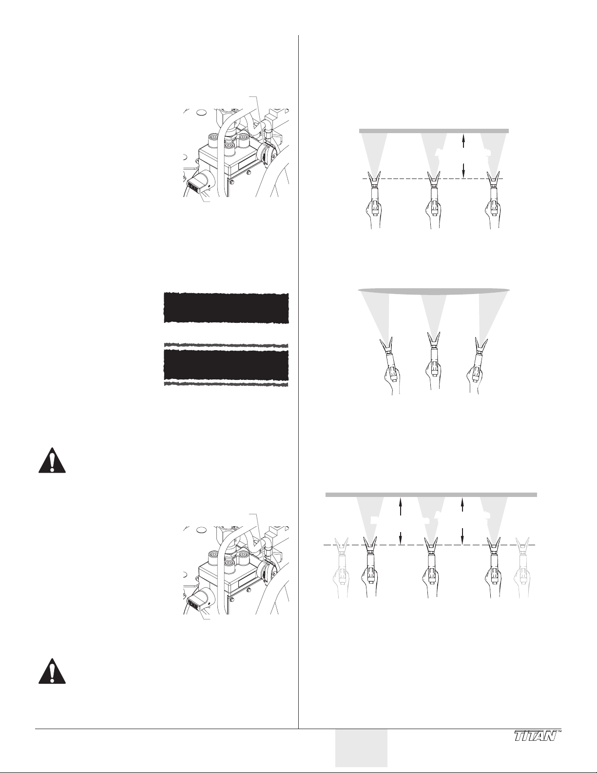
Pintura en modo sin aire
Patrón de pintura con colas
Cubra completamente con una capa uniforme
Mantenga la descarga suave y a una velocidad constante.
Capa pesada
No exione la muñeca al momento de pulverizar.
Capa ligeraCapa ligera
la descarga
la descarga
el gatillo
el gatillo
Forma adecuada de oprimir el gatillo de la pistola pulverizadora
Use el modo sin aire para pulverizaciones a alta presión en general
(presión de la bomba desde 500 a 2800 PSI).
1. Asegúrese de que la manguera de pulverización sin aire no
tenga torceduras y de que esté lejos de objetos cortantes.
2. Gire la válvula de control de
presión en contra del sentido
de las agujas del reloj al ajuste
PRIME/SPRAY
mínimo.
3. Gire la válvula PRIME/SPRAY a
SPRAY.
4. Mueva el interruptor ON/OFF
de la bomba a la posición ON.
5. Gire la válvula de control
de presión en el sentido de
las agujas del reloj al ajuste
máximo. La manguera de
pintura se debe endurecer en
la medida que pase pintura a
Válvula de control
de presión
través de ella.
6. Desbloquee la gatillo de pistola.
7. Oprima el gatillo de la pistola pulverizadora para eliminar el
aire que haya en la manguera del material.
8. Cuando el material alcance la punta de pulverización,
pulverice en un área de prueba para vericar el patrón de
pulverización.
9. Use el mínimo ajuste de
presión que se necesite
para obtener un buen
patrón de pulverización.
Si se ajusta demasiada
Buen patrón de pulverización
presión, el patrón de
pulverización será
demasiado suave. Si se
ajusta demasiada poca
presión, aparecerán colas
en la pulverización o
la pintura salpicará en
“esputos” en lugar de en
una pulverización na.
Procedimiento para el alivio de la presión
No olvide seguir el procedimiento para alivio
de la presión cuando pare el pulverizador por
cualquier motivo, incluyendo labores de reparación,
mantenimiento o ajuste de cualquier pieza del sistema
pulverizador, sustitución o limpieza de boquillas o
preparación para limpieza.
1. Gire la válvula de control de
presión en contra del sentido
de las agujas del reloj al ajuste
mínimo.
2. Gire la válvula PRIME/SPRAY a
la posición PRIME.
3. Oprima el gatillo de la pistola
para retirar cualquier presión
que todavía pueda quedar en
la manguera.
4. Bloquee la pistola girando
el seguro del gatillo hasta
que quede en posición de
bloqueado (consulte el
manual de la pistola).
Peligro de inyección. No realice pulverizaciones sin
haber instalado la protección de la punta. NUNCA
oprima el gatillo de la pistola a menos que la punta se
encuentre girada completamente a la posición para
pulverizar o en aquella destrabada. SIEMPRE enganche
el bloqueo del gatillo de la pistola antes de retirar, de
reemplazar o de limpiar la punta.
PRIME/SPRAY
Válvula de control
de presión
Válvula
Válvula
Técnica de pulverización
La clave de un buen trabajo de pintura es proporcionar una capa
uniforma sobre la totalidad de la supercie. Esto se logra dando
descargas uniformes. Mantenga el brazo en movimiento a una
velocidad constante y mantenga la pistola pulverizadora a una
distancia constante de la supercie. La mejor distancia para realizar
pulverizaciones es de 10 a 12 pulgadas (de 25 a 30 cm) entre la punta
de pulverización y la supercie.
Aproximadamente
10 a 12 pulgadas
Mantenga la pistola pulverizadora en ángulo recto respecto a la
supercie. Esto quiere decir que debe mover hacia delante y hacia
atrás el brazo completo en lugar de sólo exionar la muñeca.
Mantenga la pistola pulverizadora perpendicular a la supercie, de
otro modo un extremo del patrón será más grueso que el otro.
Se debe oprimir el gatillo de la pistola pulverizadora encendiéndola
y apagándola con cada descarga. Esto ahorrará pintura y evitará
que ésta se acumule al nal de la descarga. No oprima el gatillo de
la pistola a la mitad de una descarga. Esto dará como resultado una
pulverización desigual y una cobertura llena de manchones.
Mantenga uniforme
la descarga
Comience
Tire
Sobreponga cada descarga en alrededor de un 30%. Esto garantizará
una capa uniforme.
Cuando pare de pintar, cierre el bloqueo del gatillo de la pistola, gire
al válvula de control de presión de aire en contra del sentido de las
agujas del reloj hasta su ajuste mínimo y ajuste el botón de cebado
en PRIME. Gire el interruptor del motor hasta OFF y desenchufe la
pulverizadora.
Si cree que se alejará durante más de una hora, siga el procedimiento
de limpieza a corto plazo descrito en la sección Limpieza de este
manual.
Aproximadamente
10 a 12 pulgadas
Manténgala ja
Suelte
Termine
© Titan Tool. Todos los derechos reservados. 27
Español
Page 28
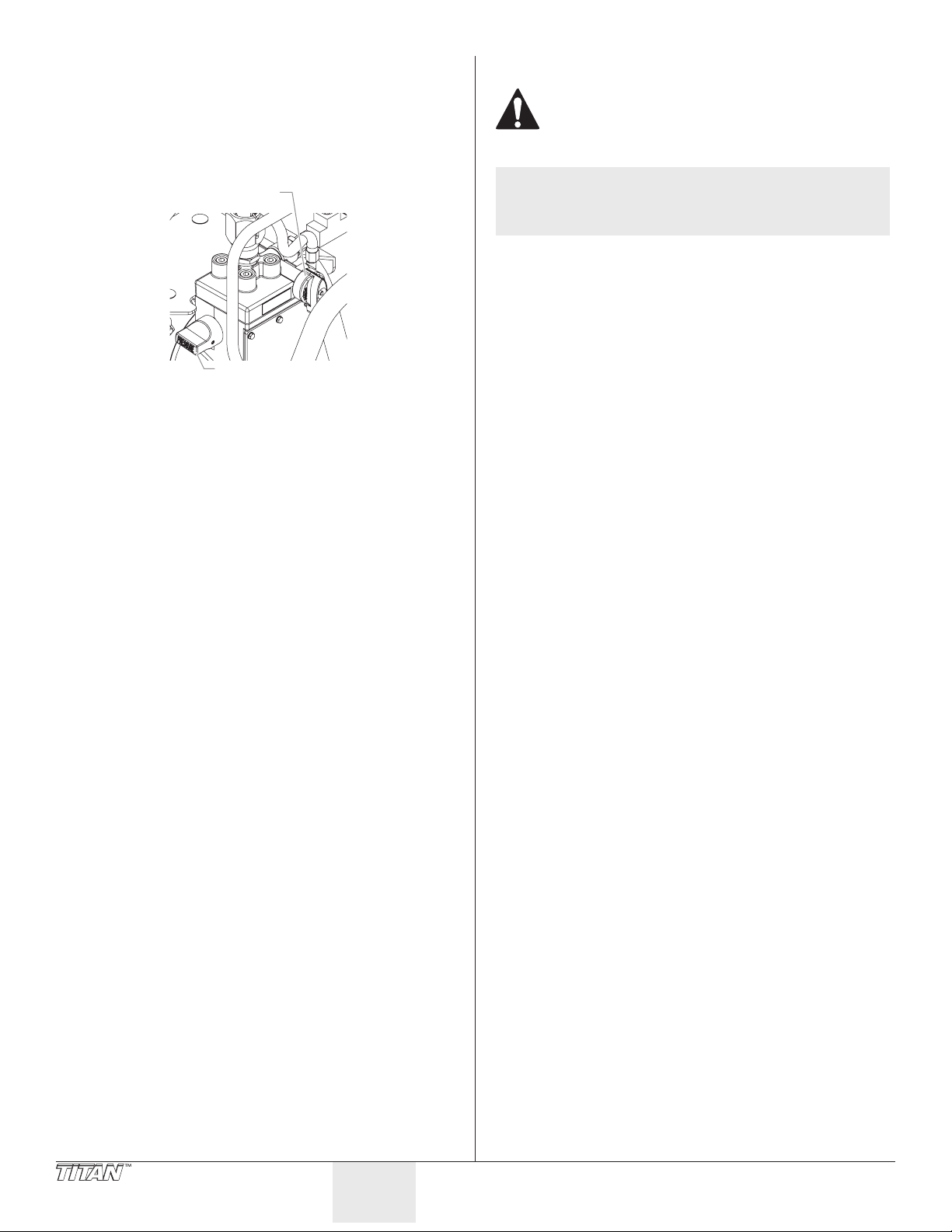
Limpieza
Válvula
de presión
Almacenamiento a largo plazo
Almacenamiento durante la noche
Detención
1. Gire la válvula de control de presión en contra del sentido de
las agujas del reloj al ajuste mínimo.
2. Gire la válvula PRIME/SPRAY a PRIME.
PRIME/SPRAY
Válvula de control
3. Mueva el interruptor ON/OFF de la bomba a la posición OFF.
4. Mueva el interruptor ON/OFF del compresor a la posición OFF.
5. Espere un par de segundos, luego oprima el gatillo de la
pistola en el recipiente de materiales para liberar la presión
de uidos acumulada en la bomba y la presión del aire del
compresor.
6. Bloquee la pistola girando el seguro del gatillo hasta que
quede en posición de bloqueado (consulte el manual de la
pistola).
7. Desenchufe la unidad.
8. Sólo en caso de trabajar con materiales a base de látex,
vierta 1/2 taza de agua en la parte superior de la pintura a
n de evitar que ésta se seque. Para otros materiales, selle el
recipiente de material, manteniendo la manguera de retorno
en la pintura.
9. Envuelva la pistola pulverizadora en un paño húmedo y
póngala en una bolsa plástica. Selle herméticamente la bolsa.
10. Ubique la unidad en un lugar seguro alejado del sol que sirva
de almacenamiento a corto plazo.
Arranque
1. Retire la pistola de la bolsa plástica.
2. Para los materiales de látex, revuelva el agua en la pintura.
Para todos los otros materiales, retire la cubierta del recipiente
de materiales y revuelva la pintura.
3. Realice el procedimiento correspondiente en la sección
“Pintura” de este manual para el tipo de pulverización que se
realizará.
No permita que se acumule pintura en el motor o
éste se sobrecalentará. No permita que entren en
contacto solventes inflamables con el motor o podrían
inflamarse.
NOTA: Si pulveriza con pintura de látex, use agua jabonosa
tibia para limpiar. Si usa aceite o pinturas a base
de alquid, use volátiles minerales o diluyente de
pintura.
IMPORTANTE: No use volátiles minerales o diluyente de pintura
en pintura de látex o la mezcla se convertirá en una sustancia
como jalea que es difícil de quitar.
Limpieza de la tolva de pintura
Use el siguiente procedimiento para limpiar el material de la tolva de
pintura.
1. Bloquee la pistola girando el seguro del gatillo hasta que
quede en posición de bloqueado (consulte el manual de la
pistola.
2. Gire el mando de control de presión en el sentido contrario a
las agujas del reloj hasta la posición mínima.
3. Coloque la válvula PRIME/SPRAY (cebar/pulverizar) en la
posición PRIME.
4. Coloque el interruptor de encendido/ apagado en la posición
OFF (apagado).
5. Dirija el tubo de retorno hacia el interior del recipiente del
material original.
6. Coloque el interruptor encendido/apagado del motor en la
posición ON.
7. Gire el mando de control de presión hasta la mitad de la
presión máxima. Así se eliminará el material restante de la
tolva de pintura por la bomba, hacia arriba por el tubo de
retorno hasta el recipiente con el material.
8. Gire el mando de control de presión en el sentido contrario a
las agujas del reloj hasta la posición de presión mínima.
9. Apriete el gatillo de la pistola para liberar presión y bloquee la
pistola.
10. Retire la boquilla pulverizadora y el protector y colóquelos en
un recipiente con agua o un disolvente adecuado para el tipo
de material con el que esté pintando.
11. Rellene la tolva de pintura con agua o con un disolvente
adecuado para el tipo de material con el que esté pintando.
12. Dirija el tubo de retorno hacia el cubo de residuos.
13. Aumente la temperatura hasta la mitad de la presión máxima.
Deje que el agua o el disolvente circulen durante 2-3 minutos
para expulsar el material de la bomba, la tolva de pintura y el
tubo de retorno.
28 © Titan Tool. Todos los derechos reservados.
Español
Page 29

Limpieza del tubo de aspiración opciónal
del compresor
Interruptor de ON/OFF
Válvula
de presión
Válvula PRIME/SPRAY
1. Gire la válvula de control de
presión en contra del sentido de
las agujas del reloj hasta el ajuste
mínimo.
2. Gire la válvula PRIME/SPRAY a
PRIME.
3. Mueva el interruptor ON/OFF de
la bomba a la posición OFF.
4. Mueva el interruptor ON/OFF del
compresor a la posición OFF.
5. Espere un par de segundos, luego
oprima el gatillo de la pistola en
el recipiente de materiales para liberar la presión de uidos
acumulada en la bomba, así como también la presión del aire
del compresor.
6. Bloquee la pistola girando el seguro del gatillo hasta que
quede en posición de bloqueado (consulte el manual de la
pistola).
7. Retire la manguera de aspiración del material y manténgala
sobre una cubeta de agua o solvente. Deje la manguera de
retorno en la cubeta del material.
IMPORTANTE: No use volátiles minerales ni diluyente de pintura
en pintura de látex, la mezcla se convertirá en una sustancia
como jalea que es difícil de quitar.
8. Mueva el interruptor ON/OFF de la bomba a la posición ON.
9. Gire la válvula de control de presión a la mitad de la presión
máxima. Esto arrastrará el material restante en la manguera
de aspiración a través de la bomba, por la manguera de
retorno y hasta la cubeta del material.
10. Gire la válvula de control de presión en contra del sentido de
las agujas del reloj al ajuste mínimo.
11. Retire la punta de pulverización y la protección y colóquelas
en un recipiente con el solvente adecuado.
12. Coloque la manguera de aspiración y la manguera de retorno
conectadas en el recipiente con agua o solvente adecuado.
13. Aumente la presión a la mitad del máximo. Deje que el agua o
solvente circule durante 2 a 3 minutos para sacar la pintura de
la bomba, de la manguera de aspiración y de la manguera de
retorno.
Interruptor de ON/OFF
de la bomba
Limpieza de la manguera de pintura
1. Gire la válvula de control de presión en contra del sentido de
las agujas del reloj al ajuste de presión mínima.
2. Gire la válvula PRIME/SPRAY a
SPRAY.
3. Desbloquee la gatillo de pistola.
4. Oprima cuidadosamente el
gatillo de la pistola sin la punta
de pulverización, en contra
del interior del recipiente de
materiales.
5. Lentamente gire la válvula
de control de presión en el
sentido de las agujas del reloj
hasta que el material comience
a uir dentro del recipiente.
Tan pronto como el agua o el
solvente comiencen a entrar en el recipiente, suelte el gatillo.
6. Apunte al agua o solvente limpio y continúe circulando por
otros 5 minutos para limpiar completamente la manguera, la
bomba y la pistola pulverizadora.
7. Gire la válvula de control de presión en contra del sentido de
las agujas del reloj al ajuste mínimo.
8. Gire la válvula PRIME/SPRAY a PRIME.
9. Oprima el gatillo de la pistola en el recipiente de agua o
solvente para liberar la presión de uidos acumulada en la
bomba.
10. Bloquee la pistola girando el seguro del gatillo hasta que
quede en posición de bloqueado (consulte el manual de la
pistola).
11. Mueva el interruptor ON/OFF de la bomba a la posición OFF.
PRIME/SPRAY
Válvula de control
Limpieza nal
1. Retire el conjunto de tolve o conjunto de aspiración de la
válvula de admisión.
2. Limpie los hilos de la válvula de admisión con un paño
húmedo.
3. Llene la válvula de admisión con agua o con un aceite
domestico ligero.
4. Asegúrese de que la válvula PRIME/SPRAY esté ajustada en
PRIME y de que la válvula de control de presión esté girada en
contra del sentido de las agujas del reloj a su ajuste mínimo
de presión.
5. Encienda la bomba moviendo el interruptor ON/OFF de la
bomba a la posición ON.
6. Aumente la presión girando la válvula de control de presión
1/2 vuelta en el sentido de las agujas del reloj.
7. Gire la válvula PRIME/SPRAY a SPRAY para distribuir el aceite.
NOTA: La limpieza y lubricación adecuadas de la bomba
luego de su uso son los pasos más importantes que
se deben realizar para asegurar un funcionamiento
adecuado luego del almacenamiento.
8. Gire la válvula de control de presión en contra del sentido de
las agujas del reloj al ajuste mínimo.
9. Gire la válvula PRIME/SPRAY a PRIME.
10. Desbloquee y oprima el gatillo de la pistola para retirar
cualquier presión que todavía pueda quedar en la manguera.
11. Bloquee la pistola girando el seguro del gatillo hasta que
quede en posición de bloqueado (consulte el manual de la
pistola).
12. Apague la bomba moviendo el interruptor ON/OFF de la
bomba a la posición OFF.
13. Retire la manguera del material y la manguera de aire de
la pistola pulverizadora por medio de dos llaves ajustables.
Consulte el Manual del propietario para obtener instrucciones
de limpieza para la pistola.
14. Limpie toda la unidad, la manguera y la pistola con un paño
húmedo para retirar la pintura acumulada.
© Titan Tool. Todos los derechos reservados. 29
Español
Page 30
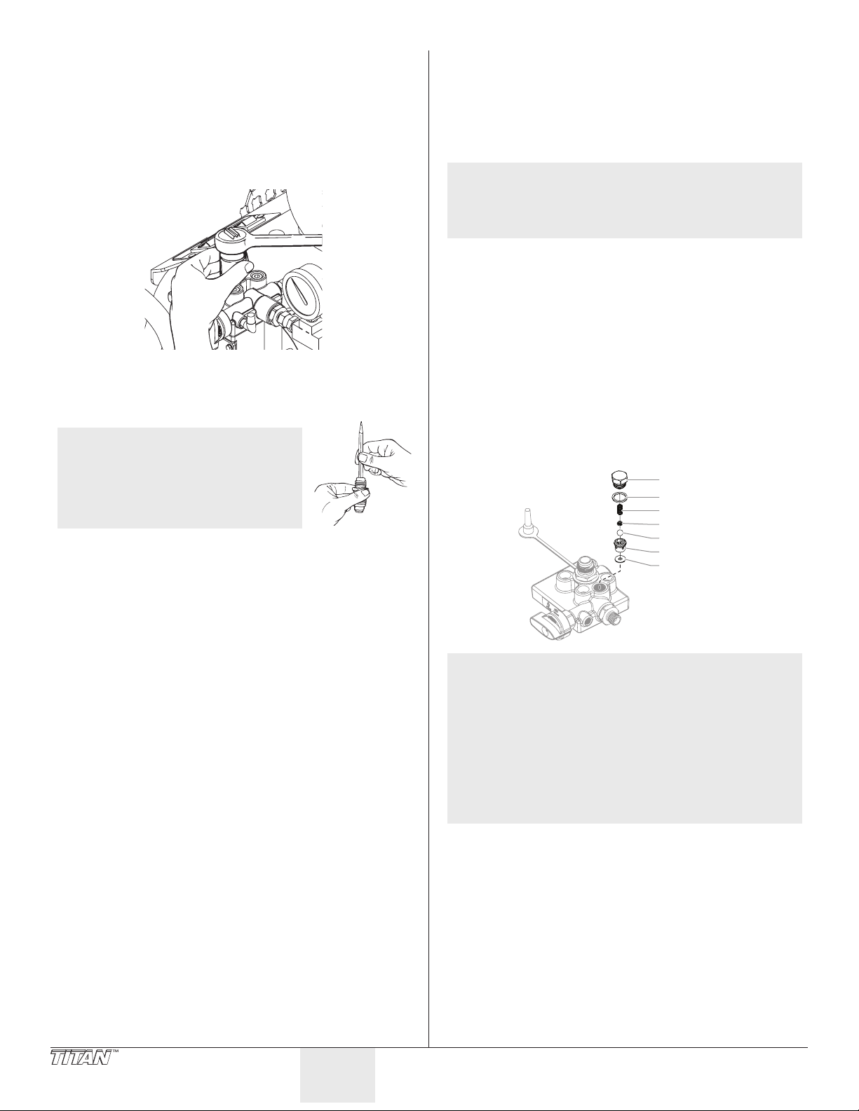
Mantenimiento
o
Siga estos procedimientos cuando encuentre los inconvenientes que
se indican en la sección de solución de problemas.
Retiro y limpieza de la válvula de admisión
1. Realice el procedimiento para el alivio de la presión, luego
apague y desenchufe la unidad.
2. Retire el conjunto de la válvula de admisión usando una llave
de cubo de 27 milímetros.
3. Pruebe el movimiento de la válvula empujándola desde
el extremo abierto del alojamiento de la válvula con un
destornillador o con el extremo para borrar de un lápiz.
Debería moverse cerca de 1/16 de pulgada (1,58 mm). Si no se
mueve, debe ser limpiada o reemplazada.
NOTA: Se debe lubricar la válvula
de admisión después de
cada trabajo. Esto reducirá o
eliminará problemas de cebado
la próxima vez que se use la
unidad y además prolongará la
vida útil de la válvula.
4. Limpie completamente el conjunto de la válvula con agua o
con el solvente adecuado. Use un cepillo pequeño.
5. Si se limpió adecuadamente la válvula y el agua gotea del
fondo, la válvula se desgastó y es necesario reemplazarla. Una
válvula adecuadamente asentada, llena de agua y mantenida
en posición vertical no goteará.
6. Instale una válvula nueva o limpia en el bloque de la bomba y
luego llénela con aceite ligero o con solvente.
Retiro y limpieza de la válvula de salida
Puede ser necesario retirar y limpiar la válvula de salida o reemplazar
las piezas del interior de la válvula desgastada por el uso normal.
1. Retire el tuerca de la válvula de salida con una llave.
2. Retire y limpie el tope esférico y el pequeño resorte en el
interior de la válvula por medio de un gancho metálico o
pinzas. Reemplace el resorte si está roto o desgastado.
NOTA: El resorte se fabrica a una tensión muy especíca.
No lo estire. No coloque un sustituto no autorizado.
Consulte el diagrama de las piezas del conjunto de
la bomba de pintura para obtener el número de las
piezas de repuesto adecuadas.
3. Retire el conjunto de asiento y bola.
4. Limpie a fondo todas las piezas. Si la bola o el asiento
muestran cualquier señal de desgaste o daño, reemplácelos
con piezas nuevas. Esta bola de carburo se debe sellar
rmemente contra su asiento para que la válvula funcione
adecuadamente.
5. Antes de volver a ensamblar cubra todas las piezas con una
delgada capa de aceite ligero.
6. Deje caer la bola de la válvula.
7. Inserte el protector y el resorte y vuelva a colocar el cuerpo de
la válvula. Asegúrese de que la junta tórica esté bien colocada
y de que la lengua de la tapa se ajuste en el interior del
resorte.
8. Apriete rmemente el cuerpo de la válvula con una llave
ajustable. No apriete excesivamente.
Tuerca
Junta tórica
Resorte
Tope esféric
Bola
Asiento
Sello
NOTA: Es casi imposible detectar visualmente el desgaste
Si la válvula está defectuosa, el tapón terminal se
30 © Titan Tool. Todos los derechos reservados.
Español
en la bola. Para probar si un conjunto de válvula de
salida está desgastado, gire la válvula de control de
presión en el sentido de las agujas del reloj hasta
su ajuste máximo y deje correr agua sólo a través
de la bomba durante 10 a 15 minutos, sin oprimir el
gatillo de la pistola.
sentirá muy caliente al tacto. Si está funcionando
correctamente, permanecerá aproximadamente a la
misma temperatura del agua que corre a través de
ésta.
Page 31

Solución de problemas
Problema
A. La unidad no arranca.
B. La bomba arranca pero no
arrastra pintura cuando la
válvula PRIME/SPRAY (CEBAR/
PULVERIZAR) está ajustada en
PRIME.
C. La bomba arrastra pintura pero
la presión cae cuando se oprime
el gatillo de la pistola.
D. Aparecen colas en el patrón de
pintura.
E. La sobrecarga térmica
desconectó y apagó la bomba.
F. El compresor no arranca.
G. El compresor arranca pero no
con el aire suciente.
Causa
1. La unidad no está enchufada.
2. El interruptor ON/OFF (ENCENDIDO/
APAGADO) está ajustado en OFF.
3. Se quemó un fusible de la unidad.
4. El enchufe de la pared tiene bajo voltaje o no
tiene voltaje.
5. Se apagó la unidad mientras todavía estaba
con presión.
6. El cable de extensión está dañado o tiene
poca capacidad.
7. Se desconectó la sobrecarga térmica de la
unidad.
8. Hay un problema con el motor.
1. La bomba no se ceba adecuadamente o ha
perdido cebado.
2. La cubeta de pintura está vacía o la manguera
de aspiración no está totalmente sumergida
en la pintura.
3. El ltro de aspiración está obstruido.
4. La manguera de aspiración está suelta en la
válvula de admisión.
5. La válvula de admisión está atascada.
6. La válvula de salida está atascada.
7. La válvula PRIME/SPRAY está tapada.
8. La válvula de admisión está desgastada o
dañada.
9. Hay un problema con el diafragma.
10. El nivel de aceite hidráulico está bajo o vacío.
1. La punta de pulverización está desgastada.
2. El ltro del conjunto de aspiración está
obstruido.
3. El ltro de la pistola o de la punta de
pulverización está tapada.
4. La pintura es demasiado pesada o gruesa.
5. El conjunto de la válvula de salida está sucio o
desgastado.
6. El conjunto de la válvula de admisión está
dañado o desgastado.
1. La presión de uidos se ajustó demasiado
bajo.
2. La presión de aire se ajustó demasiado bajo.
3. La pistola, la punta o el ltro de aspiración
está tapado.
4. La manguera de aspiración está suelta en la
válvula de admisión.
5. La punta está desgastada.
6. La pintura es demasiado espesa.
1. El motor se sobrecalentó.
2. El cable de extensión es demasiado largo o de
un calibre muy pequeño.
3. Se acumuló pintura en el motor.
4. Se arrancó el motor mientras la unidad estaba
bajo presión.
5. Se dejó la unidad bajo la luz del sol.
1. El interruptor ON/OFF del compresor está en
la posición OFF.
2. El interruptor ON/OFF del compresor está
malo.
3. Problema del compresor.
4. El oricio de descarga bajo el regulador de
aire está bloqueado.
1. El ajuste del regulador de aire es demasiado
bajo.
2. La pintura es demasiado espesa.
3. La válvula de aire en la pistola está cerrada.
4. La válvula de seguridad está mala.
Solución
1. Enchufe la unidad.
2. Gire el interruptor ON/OFF de la bomba a la posición ON.
3. Reemplace el fusible quemado con el repuesto
adecuado.
4. Pruebe adecuadamente el voltaje del suministro de
energía.
5. Gire la válvula PRIME/SPRAY a PRIME.
6. Reemplace el cable de extensión.
7. Deje enfriar el motor y traslade la unidad a un lugar más
fresco.
8. Lleve la unidad a un Centro de servicio técnico
autorizado de Titan.
1. Intente cebar otra vez la bomba.
2. Sumerja la manguera de aspiración en la pintura.
3. Limpie el ltro del conjunto de aspiración.
4. Limpie la conexión del tubo y apriételo rmemente.
5. Limpie la válvula de admisión.
6. Limpie la válvula de salida y reemplace cualquier pieza
desgastada.
7. Lleve la unidad a un Centro de servicio técnico
autorizado de Titan.
8. Reemplace la válvula de admisión.
9. Lleve la unidad a un Centro de servicio técnico
autorizado de Titan.
10. Lleve la unidad a un Centro de servicio técnico
autorizado de Titan.
1. Reemplace la punta de pulverización con una nueva.
2. Limpie el ltro del conjunto de aspiración.
3. Limpie o reemplace el ltro correspondiente. Tenga
siempre a mano ltros extras.
4. Diluya o ltre la pintura.
5. Limpie o reemplace el conjunto de la válvula de salida.
6. Reemplace la válvula de admisión.
1. Aumente la presión de uidos.
2. Aumente el ajuste del regulador de aire.
3. Limpie los ltros.
4. Apriete el adaptador de la manguera de aspiración.
5. Reemplace la punta de pulverización.
6. Diluya la pintura.
1. Deje enfriar durante 30 minutos.
2. Deje enfriar durante 30 minutos y reemplace el cable de
extensión con un cable de menor extensión o de mayor
calibre.
3. Saque la pintura del motor.
4. Vuelva a arrancar la unidad en el modo PRIME.
5. Saque a la unidad del sol.
1. Mueva el interruptor ON/OFF del compresor a la
posición ON.
2. Lleve la unidad a un Centro de servicio técnico
autorizado de Titan.
3. Lleve la unidad a un Centro de servicio técnico
autorizado de Titan.
4. Limpie el oricio de descarga.
1. Aumente el ajuste del regulador de aire.
2. Diluya la pintura.
3. Abra la válvula de aire de la pistola. Consulte el Manual
del propietario de la pistola.
4. Instale una nueva válvula de seguridad.
© Titan Tool. Todos los derechos reservados. 31
Español
Page 32
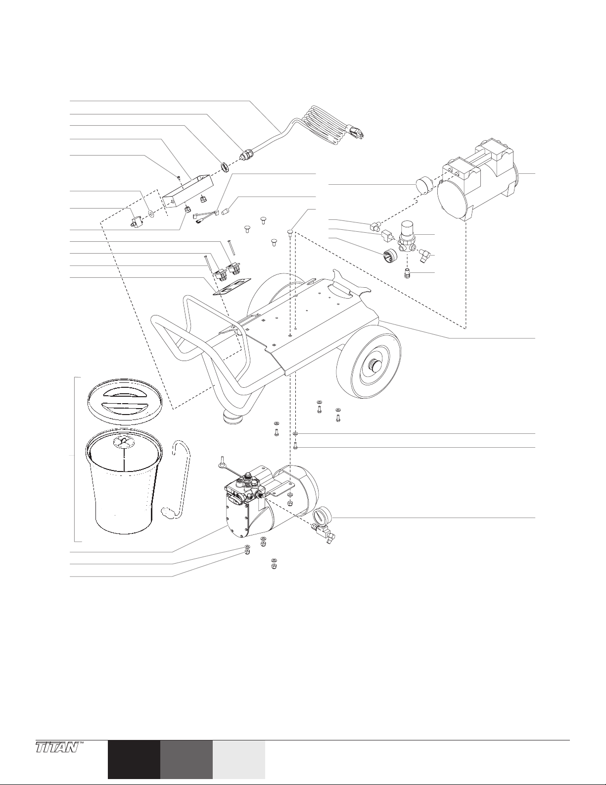
Parts List • Liste de pièces • Lista de piezas
Main Assembly • Montage principal • Conjunto principal
1
2
3
4
5
10
11
12
13
17
6
7
8
9
18
19
20
21
22
23
24
25
26
27
28
29
30
31
14
15
16
32 © Titan Tool. All rights reserved.
EspañolFrançaisEnglish
Page 33
Item
Art.
Art.
Part No.
Nº de piéce
Pieza No.
English
Description
Français
Description
Español
Descripción
1 0524313 Power cord Cordon d’alimentation Cable de alimentación 1
2 765-063 Strain relief Allégement de la souche De liberación de tensión 1
3 765-087 Lock nut Écrou de bloçage Tuerca de bloqueo 1
4 0524447 Electrical housing Boîtier électrique Alojamiento eléctrico 1
5 0524353 Ground nut Écrou de mise à la terre Tuerca de conexión a tierra 1
6 0507854 Label, “Press to Reset” Étiquette « Appuyez pour remettre
l’appareil en marche »
Etiqueta, “Press to Reset” (Presione para
reiniciar)
7 0507753 Circuit breaker, 15A Coupe-circuit, 15 A Disyuntor, 15A 1
8 0276363 Strain relief Réducteur de tension Alivio de la tensión 2
9 9850936 Compressor ON/OFF switch Interrupteur MARCHE/ARRÊT (ON/OFF)
Interruptor ON/OFF del compresor 1
du compresseur
10 9850936 Pump ON/OFF switch Interrupteur MARCHE/ARRÊT (ON/OFF)
de la pompe
Interruptor ON/OFF (ENCENDIDO/
APAGADO) de la bomba
11 0551378 Screw Vis Tornillo 2
12 0550016 Electrical cover Couvercle du circuit électrique Cubierta eléctrica 1
13 0288144 Hopper assembly Ensemble de trémie Conjunto de tolva 1
14 0524215A Diaphragm pump Pompe à diaphragme Bomba de diafragma 1
15 0088372 Flat washer Rondelle plate Arandela plana 4
16 0295615 Lock nut Écrou de blocage Contratuerca 4
17 0551415 Wire assembly Filage Conjunto de alambres 1
18 0551376 Compressor lter Filtre du compresseur Filtro del compresor 1
19 9850663 Wire nut Serre-ls Tuerca para hilos 1
20 0551354 Carriage screw Vis du chariot Tornillo del carro 4
21 816-555 Elbow, 90º Coude, 90º Tubo acodado, 90º 1
22 0551359 Tee, street Tee, street Tee, street 1
23 0276538 Gauge, air Jauge d’air Manométrica del aire 1
24 0551360 Regulator, air Régulateur de l’air Regulador de aire 1
25 54423 Elbow, 90º Coude, 90º Tubo acodado, 90º 1
26 0551361 Relief valve Soupape de décharge Válvula de alivio 1
27 0508609 Air compressor (includes
item 16)
Compresseur d’air (comprend l’article
16)
Compresor de aire (incluye el articulo
16)
28 0508190 Cart assembly Chariot Conjunto del carro 1
29 0295693 Flat washer Rondelle plate Arandela plana 4
30 0295695 Hex screw Vis hexagonale Tornillo hexagonal 4
31 0524221 Pressure gauge assembly Ensemble de jauge de pression Conjunto del manómetro 1
Not pictured / Non illustré / Sin imagen:
0524333 50 ft hose assembly Tuyau de 15,24 m (50 pi) Manguera de 50 pies 1
0291003 5 ft uid whip hose Tuyau à peinture exible de 1,52 m (5
Manguera exible para uidos de 5 pies 1
pi)
0550371 5 ft air whip hose Tuyau à air exible de 1,52 m (5 pi) Manguera exible para aire de 5 pies 1
0275640 Air coupling Raccord d’air Acoplador de aire 1
0295727 Straps Courroies Correas 3
Qty.
Qte.
Cant.
1
1
1
© Titan Tool. All rights reserved. 33
Español Français English
Page 34
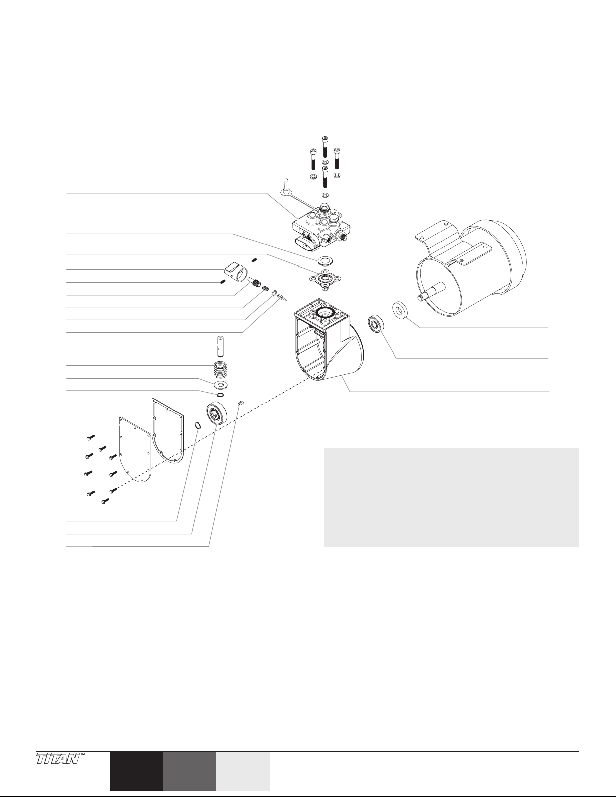
Diaphragm Pump • Pompe à diaphragme • Bomba de diafragma
(P/N 0524215A)
1
2
20
21
10
11
12
13
14
15
16
17
18
19
3
4
5
6
7
8
9
NOTE: Whenever pump head is removed for service, the
diaphragm (#3) should be replaced.
NOTA : Chaque fois que la tête de pompe est enlevé chef de
service, le diaphragme (# 3) devrait être remplacé.
NOTA: Cada vez que se elimina la altura de la bomba para
el servicio, el diafragma (# 3) debe ser reemplazado.
22
23
24
25
34 © Titan Tool. All rights reserved.
EspañolFrançaisEnglish
Page 35
Item
Art.
Art.
Part No.
Nº de piéce
Pieza No.
English
Description
1 0524213 Pump head (includes items
#2-3)
Français
Description
Español
Descripción
Tête de pompe (comprend l’articles 2-3) Altura de la bomba (incluye el articulos
2-3)
2 0270494 Diaphragm ring Bague du diaphragme Anillo del diafragma 1
3 0278240 Diaphragm Diaphragme Diafragma 1
4 0288775 Pressure control knob Bouton de réglage de la pression Válvula de control de presión 1
5 9801109 Set screw Vis de réglage Tornillo sujetador 2
6 0270529 Valve stem Tige de soupape Vástago de válvula 1
7 0047373 Pressure regulating spring Ressort de réglage de la pression Resorte regulador de presión 1
8 0089518 O-ring Joint torique Junta tórica 1
9 0089475 Pressure valve needle Pointeau de soupape de pression Aguja de la válvula de suministro 1
10 0278339 Hydraulic piston Piston hydraulique Pistón hidráulico 1
11 0005311 Piston spring Ressort du piston Resorte del pistón 1
12 0270548 Piston washer Rondelle du piston Arandela del pistón 1
13 0089456 Retainer Dispositif de retenue Aro de tope 1
14 0278359 Gasket Joint Junta 1
15 0278341 Hydraulic cover Couvercle de la pompe hydraulique Cubierta hidráulica 1
16 9800049 Screw Vis Tornillo 9
17 0047393 Retaining ring Bague de retenue Anillo de retención 1
18 0090031 Eccentric sleeve and bearing
assembly
Manchon excentrique et roulement Conjunto de manguito excéntrico y
rodamiento
19 0089829 Shaft key Clé de l’arbre Chaveta del eje 1
20 9900355 Socket screw Vis creuse Tornillo de cubo 4
21 9921601 Lock washer Rondelle d’arrêt Arandela de presión 4
22 0508612 Motor, 1/3HP (includes items
26 and 27)
Moteur, 1/3 HP (comprend les articles
26 et 27)
Motor, 1/3 HP (incluye artículos 26 y 27) 1
23 0089930 Seal Joint Sello 1
24 0089929 Ball bearing Roulement à billes Rodamiento de bolas 1
25 0278237 Hydraulic housing assembly
(includes items 23 and 24)
Carter hydraulique (comprend les
articles 23 et 24)
Conjunto del alojamiento hidráulico
(incluye artículos 23 y 24)
Not pictured / Non illustré / Sin imagen:
0270462 Fan (not shown) Ventilateur (non illustré) Ventilador (no se muestra) 1
0270612 Fan cover (not shown) Couvercle du ventilateur (non illustré) Cubierta del ventilador (no se muestra) 1
Qty.
Qte.
Cant.
1
1
1
© Titan Tool. All rights reserved. 35
Español Français English
Page 36
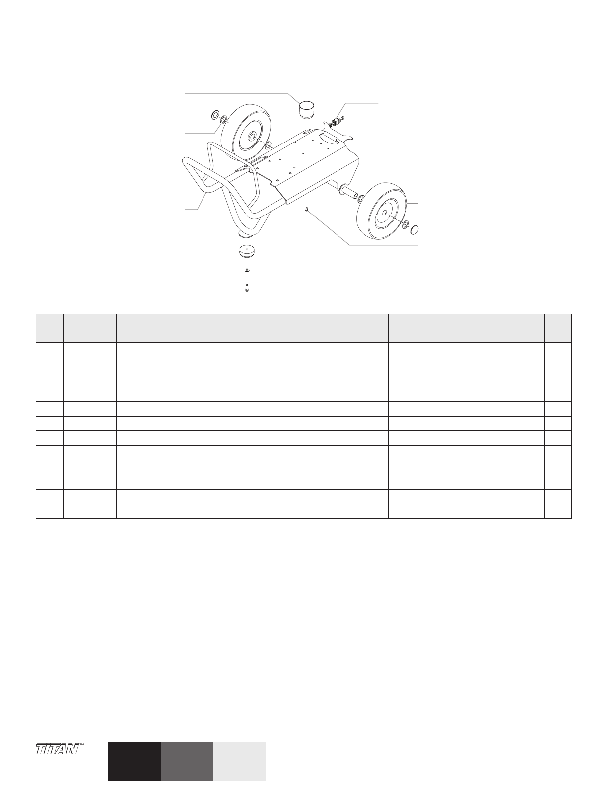
Cart Assembly • Chariot • Conjunto del carro
(P/N 0508190)
1
8
9
2
10
3
4
5
11
12
6
7
Item
Art.
Art.
Part No.
Nº de piéce
Pieza No.
English
Description
Français
Description
Español
Descripción
1 0508381 Paint cup Godet à peinture Vaso de la pintura 1
2 9890104 Cap Bouchon Tapa 2
3 0294534 Wheel spacer Entretoise de roue Separador de la rueda 4
4 0508517 Cart weldment Assemblage soudé du chariot Carro formado por elementos soldados 1
5 0090005 Pad Tapis de caoutchouc Almohadilla de goma 1
6 9820305 Washer, at Rondelle plate Arandella, plana 1
7 090026 Screw, hex head Vis, à tête hexagonale Tornillo, cabeza hexagonal 1
8 0551986 Nut with washer Vis avec rondelle Tornillo con arandela 1
9 0507937 Hose clip Clip de tuyau Agrafe de la manguera 1
10 9804916 Screw Vis Tornillo 1
11 0278373 Wheel Roue Rueda 2
12 9805230 Screw Vis Tornillo 1
Qty.
Qte.
Cant.
36 © Titan Tool. All rights reserved.
EspañolFrançaisEnglish
Page 37
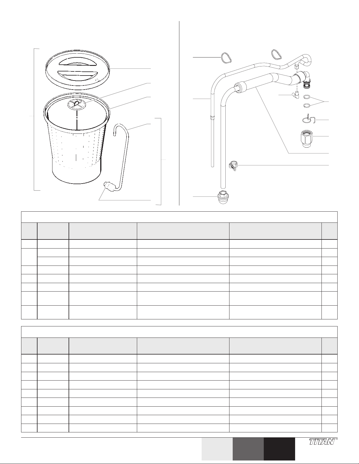
Hopper Assembly • Ensemble de trémie • Conjunto de
tolva
Suction Set (optional) • Ensemble d’aspiration
(optional) • Conjunto de aspiración (opciónal)
(P/N 0288144)
7
(P/N 0508194)
1
1
2
3
2
4
6
5
3
9
4
5
6
7
8
Hopper Assembly • Ensemble de trémie • Conjunto de tolva
Item
Art.
Art.
Part No.
Nº de piéce
Pieza No.
English
Description
Français
Description
Español
Descripción
1 0279591 Cover, hopper Couvercle, trémie Tapa de tolva 1
2 0089917 Filter screen, ne (shown) Crépine du ltre, n (montre) Pantalla de ltro, no (muestra) 1
0088871 Filter screen, coarse Crépine du ltre, grossiers Pantalla de ltro, gruesas
3 0090283 Hopper Trémie Tolva 1
4 0093865 Return tube Tube de retour Tubo de retorno 1
5 0090617 Fitting Raccord Montaje 1
6 0090560 Return tube assembly
(includes items 4-5)
7 0288144 Hopper complete (includes
Ensemble de tube de retour (comprend
l’articles 4-5)
Trémie, complet (comprend l’articles 1-6)
Conjunto de tubo de retorno (incluye el
articulos 4-5)
Tolva, completo (incluye el articulos 1-6
) 1
items 1-6)
Suction Set (optional) • Ensemble d’aspiration (optional) • Conjunto de aspiración (opciónal)
Item
Art.
Art.
Part No.
Nº de piéce
Pieza No.
English
Description
Français
Description
Español
Descripción
1 9850638 Tie wrap Attache autobloquante Arrollamiento de unión 2
2 0508614 Return hose assembly Ensemble du tuyau de retour Conjunto de la manguera de retorno 1
3 0295565 Inlet screen Crépine d’entrée Pantalla de admisión 1
4 9871105 O-Ring Joint torique Junta tórica 2
5 9822526 Retaining clip Clip de retenue Sujetador de retención 1
6 0551362 Nut Écrou Tuerca 1
7 0551102 Suction hose assembly Ensemble du tuyau d’aspiration Conjunto de la manguera de aspiración 1
8 0279459 Return hose clip Attache du tuyau de retour Sujetador de la manguera de retorno 1
9 0551356 Elbow, 90º Coude, 90º Tubo acodado, 90º 1
Qty.
Qte.
Cant.
1
Qty.
Qte.
Cant.
© Titan Tool. All rights reserved. 37
Español Français English
Page 38

Pump Head Assembly • Ensemble de tête de pompe • Conjunto de la altura de la bomba
(P/N 0524213)
7
1
8
9
10
2
11
12
13
3
4
14
5
Item
Art.
Art.
Part No.
Nº de piéce
Pieza No.
English
Description
6
Français
Description
15
Español
Descripción
1 0278242 Inlet valve assembly Ensemble de soupape d’admission Conjunto de la válvula de admisión 1
2 0278655 Inlet cap Bouchon d’admission Tapa de admisión 1
3 0089482 Sealing washer, nylon Rondelle d’étanchéité, nylon Arandela de estanqueidad, nylon 1
4 0270460 Paint pump Pompe à peinture Bomba de pintura 1
5 0555850 PRIME/SPRAY valve
assembly
Ensemble de soupape de PRIME/SPRAY Conjunto de la válvula PRIME/SPRAY
(CEBAR/PULVERIZAR)
6 0270494 Ring diaphragm Anneau diaphragme Anillo de diafragma 1
7 0270487 End cap Bouchon Tapa 1
8 9970103 Seal Joint Sello 1
9 0270499 Spring Ressort Resorte 1
10 0270497 Support, spring Support, ressort Soporte, ressort 1
11 0270491 Ball Bille Bola 1
12 0270197 Ball seat Joint à billes Asiento de la bola 1
13 0089494 Outlet seal Joint de sortie Sello de salida 1
14 0288379 Fitting, outlet Raccord de sortie Adaptador de salida 1
15 0278420 Diaphragm Diaphragme Diafragma 1
Labels / Étiquettes / Etiquetas
0508783 Front logo label Étiquette de logo avant Etiqueta frontal con el logotipo
0508785 Side logo label Étiquette de logo latérale Etiqueta lateral con el logotipo
0295804 Injection warning label Étiquettes d’avertissement risque
Etiqueta de advertencia de inyección
d’injection
0295803 Explosion warning label Étiquettes d’avertissement risque
Etiqueta de advertencia de explosión
d’explosion
0295805 Shock hazard label Étiquette de risque de choc Etiqueta de peligro de descarga
eléctrica
0524733 ON/OFF label Étiquette de MARCHE/ARRÊT (ON/OFF) Etiqueta de ON/OFF (ENCENDIDO/
APAGADO)
Qty.
Qte.
Cant.
1
38 © Titan Tool. All rights reserved.
EspañolFrançaisEnglish
Page 39

Two Year Warranty
Limited Warranty
Titan Tool (“Titan”), a division of Wagner Spray Tech Corporation (“Wagner”), warrants this product against defects in material and workmanship for a period of two years following the
date of purchase by the original purchaser. During that period, Titan will repair or replace any defective or worn-out component or, at Titan’s option, refund to the original purchaser the
full purchase price for the product in exchange for the return of that product. However, Titan will not replace or repair any uid pump component on account of wear more than once
during the two year warranty period. This warranty does not cover consumable products such as lters and tips.
Lifetime Warranty on Gear Trains, Electric Motors, and Gas Engines
Titan warrants any gear train, electric motor (excluding brushes and commutators) and gas engine (excluding the clutch) in this product against defects in material and workmanship
for the lifetime of the original purchaser. If Titan determines that the foregoing warranty has been breached, Titan will repair or replace the defective components without charge or, at
Titan’s option, refund to the original purchaser the full purchase price for the product in exchange for the return of that product. Lifetime warranty on the diaphragm.
Warranty Claims
Any request for repair or replacement pursuant to the warranties above must be accompanied by the return of the applicable parts, with transportation charges prepaid, to a service
center authorized by Titan or to Wagner Spray Tech Corporation, 1770 Fernbrook Lane, Minneapolis, MN 55447.
Limitation of Remedies
THE REMEDIES SET FORTH ABOVE ARE THE EXCLUSIVE REMEDIES AVAILABLE FOR BREACH OF EXPRESS AND IMPLIED WARRANTIES. These remedies shall not be deemed to have failed of
their essential purpose so long as Titan is willing to repair or replace parts, or to refund the purchase price, as set forth above.
What Is Not Covered By This Warranty
This warranty does not cover defects or damages caused by:
• the use or installation of repair or replacement parts or accessories not manufactured by Titan;
• repair performed by anyone other than a Titan Authorized Service Center; or
• abuse, misuse, negligence, accident, faulty installation or tampering in a manner which impairs normal operation.
This warranty also does not cover equipment and accessories supplied to Titan from an original equipment manufacturer, including but not limited to hoses, tips, and accessories. Titan
will provide the purchaser with copies of the original equipment manufacturer’s express warranties provided to Titan along with the name and address of the appropriate manufacturer.
Limitation of Remedies
IN NO CASE SHALL Titan BE LIABLE FOR ANY INCIDENTAL, SPECIAL OR CONSEQUENTIAL DAMAGES OR LOSS, INCLUDING TRANSPORTATION COSTS, WHETHER SUCH DAMAGES ARE
BASED UPON A BREACH OF EXPRESS OR IMPLIED WARRANTIES, BREACH OF CONTRACT, NEGLIGENCE, STRICT TORT, OR ANY OTHER LEGAL THEORY.
Disclaimer of Implied Warranties
THE FOREGOING WARRANTIES ARE IN LIEU OF ALL OTHER WARRANTIES, EXPRESS OR IMPLIED, INCLUDING BUT NOT LIMITED TO THE IMPLIED WARRANTIES OF MERCHANTABILITY AND
FITNESS FOR A PARTICULAR PURPOSE.
No Ability To Transfer
This warranty is extended to the original purchaser only and is not transferable.
Titan 30-Day Satisfaction Guarantee
If, within a 30-day period from the date of purchase, you are not totally satised with a Titan unit, you may return it for full credit toward another Titan product of equal or
greater value.
Material Safety Data Sheets (MSDS) are available on Titan’s website or by calling Technical Service.
Garantie Limitée
Deux ans de garantie
Titan Tool (“Titan”), une division de Wagner Spray Tech Corporation (“Wagner”), garantit l’absence de tout défaut de matériaux ou de main-d’œuvre à l’acheteur initial au détail pendant
2 ans à compter de la date d’achat. Pendant cette période, Titan s’engage à réparer ou à remplacer toute pièce défectueuse ou usée ou, si elle le juge opportun, à rembourser à l’acheteur
initial la totalité du prix d’achat du produit en échange du retour du produit concerné. Pendant ladite période de garantie, Titan ne remplacera pas et ne réparera pas plus d’une fois, une
ou plusieurs pièces de la pompe endommagée(s) en raison de l’usure. La présente garantie ne s’applique pas aux produits consommables tels que les ltres et les têtes de pulvérisation.
Garantie à vie sur les engrenages, les moteurs électriques et les moteurs à essence
Titan garantit tous les engrenages, les moteurs électriques (à l’exception des balais et des commutateurs) et les moteurs à essence (à l’exception de l’embrayage) composant ce produit
contre les défauts de matériaux et de fabrication pendant toute la vie de l’acheteur initial. Si Titan détermine que la garantie en vigueur a été violée, Titan s’engage à réparer ou à
remplacer gratuitement les pièces défectueuses ou, si elle le juge opportun, à rembourser à l’acheteur initial la totalité du prix d’achat du produit en échange du retour du produit
concerné. Garantie à vie sur le diaphragme.
Réclamations au titre de la garantie
Toute demande de réparation ou de remplacement en vertu de la présente garantie devra être accompagnée du retour des pièces concernées, frais de transport payés d’avance, à un
centre de réparation agréé par Titan ou à Wagner Spray Tech Corporation, 1770 Fernbrook Lane, Minneapolis, MN 55447, États-Unis.
Limitation des recours
LES RECOURS QUI PRÉCÈDENT SONT LES SEULS RECOURS APPLICABLES EN CAS DE VIOLATION DES GARANTIES EXPRESSES ET IMPLICITES. On ne pourra considérer que ces recours ont
été insusants tant que Titan acceptera de réparer ou de remplacer les pièces ou de rembourser le prix d’achat comme il est stipulé aux présentes.
Ce qui n’est pas couvert par la présente garantie
La présente garantie ne s’applique pas aux défauts ou aux dommages causés par :
• l’utilisation ou l’installation de pièces réparées ou de pièces rechange ou d’accessoires non fabriqués par Titan.
• les réparations réalisées par une entité autre qu’un centre de réparation agréé par Titan; ou
• l’abus, une utilisation malveillante, la négligence, un accident, une installation défectueuse ou des modications empêchant un fonctionnement normal.
Cette garantie ne couvre pas non plus les équipements et les accessoires fournis à Titan par un fabricant d’équipement d’origine incluant, sans toutefois s’y limiter, les tuyaux, les têtes de
pulvérisation et les accessoires. Titan fournira à l’acheteur des copies des garanties expresses du fabricant d’équipement d’origine fournies à Titan avec le nom et l’adresse du fabricant.
Limitation des recours
Titan NE POURRA EN AUCUN CAS ÊTRE TENUE RESPONSABLE DE TOUT DOMMAGE OU DE TOUTE PERTE DE NATURE INDIRECTE, SPÉCIALE OU CONSÉCUTIVE, INCLUANT LES FRAIS DE
TRANSPORT, QUE CES PERTES OU DOMMAGES SOIENT FONDÉS SUR UNE VIOLATION DES GARANTIES EXPRESSES ET IMPLICITES, UNE RUPTURE DE CONTRAT, DE LA NÉGLIGENCE, UN
DÉLIT CIVIL OU TOUTE AUTRE THÉORIE JURIDIQUE.
Stipulation d’exonération des garanties implicites
LES GARANTIES PRÉCÉDENTES REMPLACENT TOUTE AUTRE GARANTIE EXPRESSE OU IMPLICITE INCLUANT, SANS TOUTEFOIS S’Y LIMITER, LES GARANTIES IMPLICITES DE QUALITÉ
MARCHANDE ET D’APTITUDE À UN USAGE PARTICULIER
Aucune possibilité de transfert
La présente garantie est oerte seulement à l’acheteur initial et n’est pas transférable.
Garantie de satisfaction de 30 jours de Titan
Si, dans les 30 jours suivants la date d’achat, vous n’êtes pas totalement satisfait du produit de Titan, vous pouvez le retourner et obtenir un crédit pour un autre produit Titan
de valeur égale ou supérieure.
Des ches techniques de sécurité des produits (FTSS) sont disponibles sur le site Internet
de Titan ou par téléphone en vous adressant au service à la clientèle.
© Titan Tool. All rights reserved. 39
Page 40

Garantía limitada
Garantía de dos años
Titan Tool (“Titan”), una división de Wagner Spray Tech Corporation (“Wagner”), garantiza este producto frente a defectos en el material y en la mano de obra durante un período de dos
años a partir de la fecha de compra por parte del comprador original. Durante ese período, Titan reparará o reemplazará cualquier componente defectuoso o desgastado o, a criterio de
Titan, reembolsará al comprador original el precio total de compra del producto cambiado por la devolución de éste. Sin embargo, Titan no reemplazará ni reparará componente alguno
de la bomba de uidos por desgaste más de una vez durante el período de garantía de dos años. Esta garantía no cubre los productos consumibles tales como ltros o puntas.
Garantía limitada en trenes de engranajes, motores eléctricos y motores de gas
Titan garantiza cualquier tren de engranajes, motor eléctrico (sin incluir escobillas ni conmutadores) y motor de gas (sin incluir el embrague) en este producto frente a defectos en
el material y en la mano de obra por toda la vida del comprador original. Si Titan determina que se ha incumplido esta garantía anterior, reparará o reemplazará los componentes
defectuosos sin costo o, a criterio de Titan, reembolsará al comprador original el precio total de compra del producto cambiado por la devolución de éste. Garantía de por vida del
diafragma.
Reclamos de la garantía
Cualquier solicitud de reparación o reemplazo conforme a las garantías anteriores debe estar acompañada de la devolución de las piezas aplicables a un centro de servicio técnico
autorizado por Titan, o bien a Wagner Spray Tech Corporation, 1770 Fernbrook Lane, Minneapolis, MN 55447, con los cargos de transporte prepagados.
Limitación de recursos
LOS RECURSOS ESTABLECIDOS ANTERIORMENTE SON LOS RECURSOS EXCLUSIVOS DISPONIBLES PARA EL INCUMPLIMIENTO DE LAS GARANTÍAS EXPRESAS E IMPLÍCITAS. No se
considerará que estos recursos hayan fallado a sus propósitos esenciales mientras Titan esté dispuesto a reparar o reemplazar piezas, o a reembolsar el precio de compra, según se
establece anteriormente.
Aspectos que no cubre esta garantía
Esta garantía no cubre defectos o daños causados por:
• El uso o la instalación de repuestos o accesorios que no hayan sido fabricados por Titan.
• Reparaciones realizadas por cualquier persona distinta de un Centro de servicio técnico autorizado de Titan o
• Abuso, uso inadecuado, negligencia, accidentes, instalaciones defectuosas o manejo que afecte la operación normal.
Esta garantía tampoco cubre equipo y accesorios suministrados a Titan de parte de un fabricante de equipos originales, incluyendo entre otros, mangueras, puntas y otros accesorios.
Titan le proporcionará al comprador copias de las garantías expresas del fabricante de los equipos originales, proporcionadas a su vez a Titan, junto con el nombre y la dirección del
fabricante correspondiente.
Limitación de recursos
EN NINGÚN CASO Titan SERÁ RESPONSABLE DE DAÑO O PÉRDIDA INCIDENTAL ALGUNA, ESPECIAL O RESULTANTE, INCLUYENDO LOS COSTOS DE TRANSPORTE, SI TALES DAÑOS SE
BASAN EN UN INCUMPLIMIENTO DE LAS GARANTÍAS EXPRESAS O IMPLÍCITAS, INCUMPLIMIENTO DE CONTRATO, NEGLIGENCIA, RECLAMACIÓN OBJETIVA O CUALQUIER OTRA TEORÍA
LEGAL.
Descargo de responsabilidad de las garantías implícitas
LAS GARANTÍAS ANTERIORES REEMPLAZAN A TODAS LAS OTRAS GARANTÍAS, EXPRESAS O IMPLÍCITAS, INCLUYENDO ENTRO OTRAS A LAS GARANTÍAS IMPLÍCITAS DE
COMERCIALIZACIÓN Y ADECUACIÓN PARA UN PROPÓSITO EN PARTICULAR.
Intransferibilidad
Esta garantía sólo se extiende al comprador original y es intransferible.
Garantía de satisfacción de 30 días de Titan
Si, dentro de un período de 30 días desde la fecha de compra, no está totalmente satisfecho con una unidad Titan, puede devolverla a cambio de un crédito total para la
compra de otro producto Titan de igual o mayor valor.
A través del sitio Web de Titan o llamando al Servicio técnico puede obtener
las chas técnicas de seguridad (MSDS, por sus siglas en inglés).
United States Sales & Service
Phone:
1-800-526-5362
Fax:
1-800-528-4826
1770 Fernbrook Lane
Minneapolis, MN 55447
international@titantool.com
International
Fax: 1-763-519-3509
1770 Fernbrook Lane
Minneapolis, MN 55447
www.titantool.com
40 © Titan Tool. All rights reserved.
 Loading...