

Page 1
Owner’s Manual
Notice d’utilisation
Manual del Propietario
Do not use this equipment before
reading this manual!
SPEEFLO
PowrLiner 2850
Model Number:
1-gun 0290008
2-gun 0290009
NOTE: This manual contains important
warnings and instructions. Please read
and retain for reference.
0117 • © Titan Tool Inc. All Rights Reserved. Form No. 0290919K
Page 2
Important Safety Information
Read all safety information before operating the
equipment. Save these instructions.
Indicates a hazardous situation which, if not avoided,
could result in death or serious injury.
To reduce the risks of re or explosion, electrical shock
and the injury to persons, read and understand all
instructions included in this manual. Be familiar with the
controls and proper usage of the equipment.
WARNING: EXPLOSION OR FIRE
Flammable vapors, such as solvent and paint vapors, in
work area can ignite or explode.
PREVENTION:
1. Use equipment only in well ventilated area. Keep a good
supply of fresh air moving through the area to keep the air
within the spray area free from accumulation of ammable
vapors. Keep pump assembly in well ventilated area. Do not
spray pump assembly.
2. Do not ll fuel tank while engine is running or hot; shut o
engine and allow to cool. Fuel is ammable and can ignite or
explode if spilled on a hot surface.
3. Eliminate all ignition sources, such as pilot lights, cigarettes,
portable electric lamps and plastic drop cloths (potential static
arc).
4. Keep work area free of debris, including solvent, rags and
gasoline.
5. Do not plug or unplug power cords, or turn power or light
switches on or o when ammable vapors are present.
6. Ground equipment and conductive objects in work area.
Make sure grounding chain is in place and reaches the
ground.
7. Use only grounded hoses.
8. Hold spray gun rmly to the side of a grounded pail when
triggering into pail.
9. If there is static sparking or if you feel a shock, stop operation
immediately.
10. Know the contents of the paint and solvents being sprayed.
Read all Material Safety Data Sheets (MSDS) and container
labels provided with the paints and solvents. Follow the paint
and solvent manufacturer’s safety instructions.
11. Do not use a paint or solvent containing halogenated
hydrocarbons. Such as chlorine, bleach, mildewcide,
methylene chloride and trichloroethane. They are not
compatible with aluminum. Contact the coating supplier
about compatibility of material with aluminum.
12. Keep a re extinguisher in work area.
WARNING: INJECTION INJURY
A high pressure paint stream produced by this equipment
can pierce the skin and underlying tissues, leading to
serious injury and possible amputation. See a physician
immediately.
PREVENTION:
1. Do not aim the gun at, or spray any person or animal.
2. Keep hands and other body parts away from the discharge.
For example, do not try to stop leaks with any part of the
body.
3. Always use the nozzle tip guard. Do not spray without the
nozzle tip guard in place.
2 © Titan Tool Inc. All rights reserved.
English
4. Only use a nozzle tip specied by the manufacturer.
5. Use caution when cleaning and changing nozzle tips. In the
case where the nozzle tip clogs while spraying,
ALWAYS lock gun trigger, shut pump o, and release all
pressure before servicing, cleaning tip or guard, or changing
tip. Pressure will not be released by turning o the motor.
The PRIME/SPRAY valve or pressure bleed valve must be
turned to their appropriate positions to relieve system
pressure. Refer to PRESSURE RELIEF PROCEDURE described in
the pump manual.
6. Do not leave the unit energized or under pressure while
unattended. When the unit is not in use, turn o the unit and
relieve the pressure in accordance with the manufacturer’s
instructions.
7. High-pressure spray is able to inject toxins into the body and
cause serious bodily injury. In the event that injection occurs,
seek medical attention immediately.
8. Check hoses and parts for signs of damage, a leak can inject
material into the skin. Inspect hose before each use. Replace
any damaged hoses or parts.
9. This system is capable of producing 3300 PSI / 22.8 MPa. Only
use replacement parts or accessories that are specied by the
manufacturer and that are rated a minimum of 3300 PSI. This
includes spray tips, nozzle guards, guns, extensions, ttings,
and hose.
10. Always engage the trigger lock when not spraying. Verify the
trigger lock is functioning properly.
11. Verify that all connections are secure before operating the
unit.
12. Know how to stop the unit and bleed pressure quickly. Be
thoroughly familiar with the controls. Pressure will not be
released by turning o the motor. The PRIME/SPRAY valve
or pressure bleed valve must be turned to their appropriate
positions to relieve system pressure. Refer to PRESSURE
RELIEF PROCEDURE described in the pump manual.
13. Always remove the spray tip before ushing or cleaning the
system.
NOTE TO PHYSICIAN:
Injection into the skin is a traumatic injury which can lead
to possible amputation. It is important to treat the injury as
soon as possible. DO NOT delay treatment to research toxicity.
Toxicity is a concern with some coatings injected directly
into the blood stream. Consultation with a plastic surgeon or
reconstructive hand surgeon may be advisable.
WARNING: GENERAL
Can cause severe injury or property damage.
PREVENTION:
1. Always wear appropriate gloves, eye protection, clothing
and a respirator or mask when painting. Hazardous vapors
– Paints, solvents, insecticides, and other materials can be
harmful if inhaled or come in contact with body. Vapors can
cause severe nausea, fainting or poisoning.
2. Do not operate or spray near children. Keep children away
from equipment at all times.
3. Do not overreach or stand on an unstable support. Keep
eective footing and balance at all times.
4. Stay alert and watch what you are doing.
5. Do not operate the unit when fatigued or under the inuence
of drugs or alcohol.
6. Do not kink or over-bend the hose. Airless hose can develop
leaks from wear, kinking and abuse. A leak can inject material
into the skin.
Page 3

Important Safety Information
7. Do not expose the hose to temperatures or pressures in excess
of those specied by manufacturer.
8. Do not use the hose as a strength member to pull or lift the
equipment.
9. Use lowest possible pressure to ush equipment.
10. Follow all appropriate local, state and national codes
governing ventilation, re prevention and operation.
11. The United States Government Safety Standards have been
adopted under the Occupational Safety and Health Act
(OSHA). These standards, particularly part 1910 of the General
Standards and part 1926 of the Construction Standards should
be consulted.
12. Before each use, check all hoses for cuts, leaks, abrasion
or bulging of cover. Check for damage or movement
of couplings. Immediately replace hose if any of those
conditions exist. Never repair a paint hose. Replace with a
conductive high-pressure hose.
13. Do not spray outdoors on windy days.
14. Always unplug cord from outlet before working on equipment
(electric models only).
IMPORTANT: Do not lift cart handle when loading or unloading.
Gasoline Engine Safety
The engine exhaust from this unit contains chemicals
known to the State of California to cause cancer, birth
defects, or other reproductive harm.
1. Gas engines are designed to give safe and dependable service
if operated according to instructions. Read and understand
the engine Owner’s Manual before operating the engine.
Failure to do so could result in personal injury or equipment
damage.
2. To prevent re hazards and to provide adequate ventilation,
keep the engine at least 1 meter (3 feet) away from buildings
and other equipment during operation. Do not place
ammable objects close to the engine.
3. Children and pets must be kept away from the area of
operation due to a possibility of burns from hot engine
components or injury from any equipment the engine may be
used to operate.
4. Know how to stop the engine quickly, and understand the
operation of all controls. Never permit anyone to operate the
engine without proper instructions.
5. Gasoline is extremely ammable and is explosive under
certain conditions.
6. Refuel in a well-ventilated area with the engine stopped. Do
not smoke or allow ames or sparks in the refueling area or
where gasoline is stored.
7. Do not overll the fuel tank. After refueling, make sure the
tank cap is closed properly and securely.
8. Be careful not to spill fuel when refueling. Fuel vapor or
spilled fuel may ignite. If any fuel is spilled, make sure the area
is dry before starting the engine.
9. Never run the engine in an enclosed or conned area. Exhaust
contains poisonous carbon monoxide gas; exposure may
cause loss of consciousness and may lead to death.
10. The muer becomes very hot during operation and remains
hot for a while after stopping the engine. Be careful not to
touch the muer while it is hot. To avoid severe burns or re
hazards, let the engine cool before transporting it or storing it
indoors.
11. Never ship/transport unit with gasoline in the tank.
Specications
Gallons per minute (GPM) 0.85 (3.22 LPM)
Maximum tip sizes one gun = 0.030”
two guns = 0.021”
Maximum pressure 3300 PSI (22.8 MPa)
Power 3.5 HP Honda gas engine
Weight 138 lbs. (62.6 kg)
Table of Contents
Safety Precautions ........................................................................... 2
Français ..........................................................................................................18
Español ...........................................................................................................36
General Description ........................................................................ 4
Trigger Lock .................................................................................................... 4
Operation ......................................................................................... 4
Fueling .............................................................................................................. 4
Setup ................................................................................................................. 5
Preparing a New Sprayer ........................................................................... 6
Preparing to Paint.........................................................................................7
Painting ............................................................................................................ 7
Operating the Front Caster ....................................................................... 8
Pressure Relief Procedure .......................................................................... 8
Cleanup ............................................................................................ 8
Cleaning the Spray Tip ................................................................................ 9
Maintenance .................................................................................... 9
General Repair and Service Notes .......................................................... 9
Maintaining the Engine .............................................................................. 9
Adjusting the Trigger Tension ................................................................. 9
Replacing the PRIME/SPRAY Valve .......................................................10
Cleaning or Replacing the Filters ..........................................................10
Replacing the Pump ON/OFF Switch ..................................................11
Replacing the Gears and/or Slider Assembly ............................ 11-12
Replacing the Transducer ........................................................................12
Servicing the Clutch Assembly ....................................................... 12-14
Servicing the Fluid Section ...............................................................15-16
Troubleshooting ............................................................................ 17
Parts Listings .................................................................................. 48
Main Assembly ............................................................................................48
Drive Assembly ............................................................................................50
Fluid Section Assembly ............................................................................54
Cart Assembly ..............................................................................................56
Front Wheel Assembly ..............................................................................58
Gun Holder Assembly ...............................................................................60
Brake Assembly ...........................................................................................60
Accessories ....................................................................................................62
Limited Warranty ........................................................................... 64
© Titan Tool Inc. All rights reserved. 3
English
Page 4
Ma
Tip Assembly
Assembly
Spray Gun (2)
Hose (50’)
Assembly
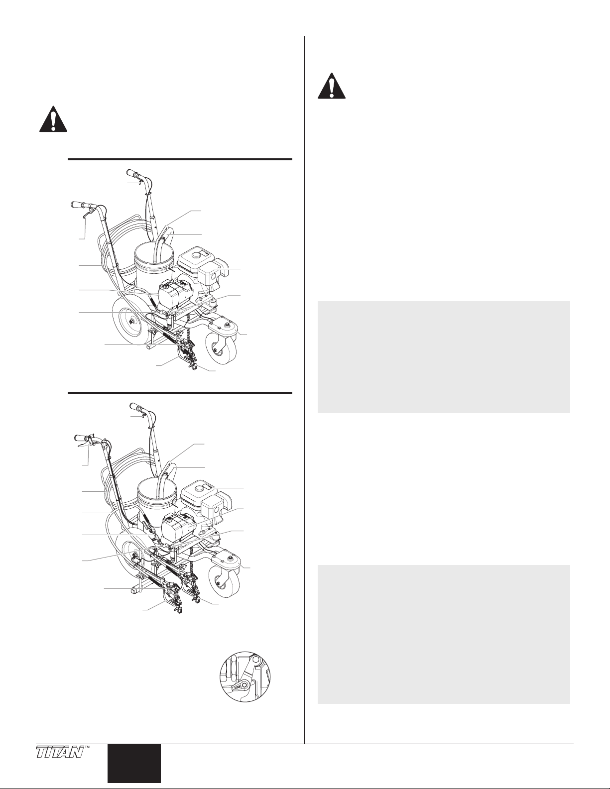
General Description
This airless line striper is a precision power tool used to spray many
types of material for many types of applications including parking
lots, curbs, and athletic elds. Read and follow this instruction
manual carefully for proper operating instructions, maintenance, and
safety information.
This equipment produces a fluid stream at extremely
high pressure. Read and understand the warnings
in the Safety Precautions section at the front of this
manual before operating this equipment.
1-Gun
Caster Trigger
Return Hose
Gun
Trigger
terial
Hose
Airless
Sprayer
Outlet
Fitting
Gun Holder
Assembly
Spray Gun
2-Gun
Caster Trigger
Gun
Trigger
Material
Material
Hose (6’)
Valve
Assembly
Outlet
Fitting
Gun Holder
Assembly (2)
Trigger Lock
Engage the trigger lock whenever the gun
is not in use.
To lock the gun, turn the trigger lock
forward and slightly down until is stops.
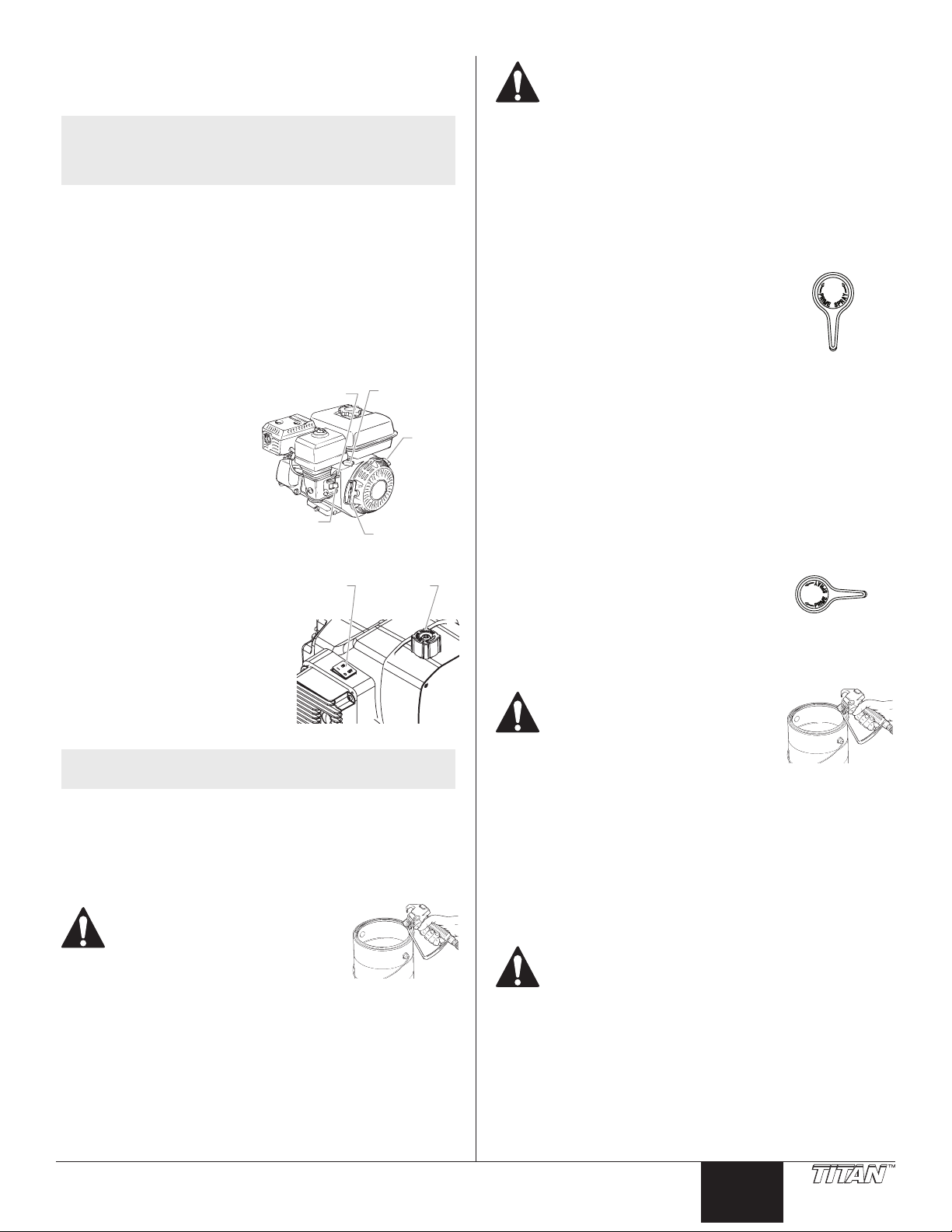
Siphon Hose
Engine
PRIME/
SPRAY
Valve
Front
Caster
Return Hose
Siphon Hose
Engine
Airless
Sprayer
PRIME/
SPRAY
Valve
Front
Caster
Tip Assembly (2)
Trigger lock in
locked position.
Operation
Fueling (gas engine)
Gasoline is extremely flammable and is explosive
under certain conditions.
• ALWAYS turn the engine o before refueling.
• Refuel in a well-ventilated area.
• Do not smoke or allow ames or sparks in the refueling area or
where gasoline is stored.
• Do not overll the fuel tank. After refueling, make sure the
tank cap is closed properly and securely.
• Be careful not to spill fuel when refueling. Spilled fuel or fuel
vapor may ignite. If any fuel is spilled, make sure the area is
dry before starting the engine.
• Avoid repeated or prolonged contact with skin or breathing of
vapor.
• Keep out of the reach of children.
Fuel Specications
• Use automotive gasoline that has a pump octane number of
86 or higher, or that has a research octane number of 91 or
higher. Use of a lower octane gasoline can cause persistent
“pinging” or heavy “spark knock” (a metallic rapping noise)
which, if severe, can lead to engine damage.
NOTE: If “spark knock” or “pinging” occurs at a steady
engine speed under normal load, change brands of
gasoline. If spark knock or pinging persists, consult
an authorized dealer of the engine manufacturer.
Failure to do so is considered misuse, and damage
caused by misuse is not covered by the engine
manufacturer’s limited warranty.
Occasionally you may experience light spark knock
while operating under heavy loads. This is no
cause for concern, it simply means your engine is
operating eciently.
• Unleaded fuel produces fewer engine and spark plug deposits
and extends the life of the exhaust system components.
• Never use stale or contaminated gasoline or an oil/gasoline
mixture. Avoid getting dirt, dust, or water in the fuel tank.
Gasolines Containing Alcohol
If you decide to use a gasoline containing alcohol (gasohol), be
sure its octane rating is at least as high as that recommended by
the engine manufacturer. There are two types of “gasohol”: one
containing ethanol, and the other containing methanol. Do not use
gasohol that contains more than 10% ethanol. Do not use gasoline
containing methanol (methyl or wood alcohol) that does not also
contain co-solvents and corrosion inhibitors for methanol. Never
use gasoline containing more than 5% methanol, even if it has cosolvents and corrosion inhibitors.
NOTE: Fuel system damage or engine performance
problems resulting from the use of fuels that
contain alcohol is not covered under the warranty.
The engine manufacturer cannot endorse the use of
fuels containing methanol since evidence of their
suitability is incomplete at this time.
Before buying gasoline from an unfamiliar station,
try to nd out if the gasoline contains alcohol. If it
does, conrm the type and percentage of alcohol
used. If you notice any undesirable operating
characteristics while using a gasoline that contains
alcohol, or one that you think contains alcohol,
switch to a gasoline that you know does not contain
alcohol.
4 © Titan Tool Inc. All rights reserved.
English
Page 5
Setup
tting
suppor
Perform the following procedure before starting the engine of a gaspowered line striper.
NOTE: The PL2850 comes in two versions, a one-gun
version and a two-gun version. All information
given in this manual applies to both units, except
where noted.
1. Ensure that the siphon hose and the return hose are attached
and secure.
2. Turn the pressure control knob fully counterclockwise to its
lowest pressure setting.
3. Make sure the pump ON/OFF switch is in the OFF position.
4. Fill the uid section oil cup with approximately one
tablespoon of piston seal lubricant (Piston Lube).
IMPORTANT: Never operate unit for more than ten seconds
without fluid. Operating this unit without fluid will cause
unnecessary wear to the packings.
5. Check the engine oil level. The gasoline engine oil level
is determined by the manufacturer. Refer to the engine
manufacturer’s service manual (supplied).
6. Close the fuel shut-o lever and ll the gas tank with gasoline.
Use only high quality, unleaded gasoline.
One-Gun Setup
1. Using a wrench, thread the 50’ airless spray hose to the outlet
tting on the sprayer. Tighten securely.
2. Attach an airless spray gun to the spray hose. Using two
wrenches (one on the gun and one on the hose), tighten
securely.
Two-Gun Setup
1. Using a wrench, thread the valve assembly (with 50’ hose
attached) to the outlet tting on the sprayer. Tighten
securely.
2. Using a wrench, thread the 6’ airless spray hose to the top
outlet tting on the valve assembly. Tighten securely.
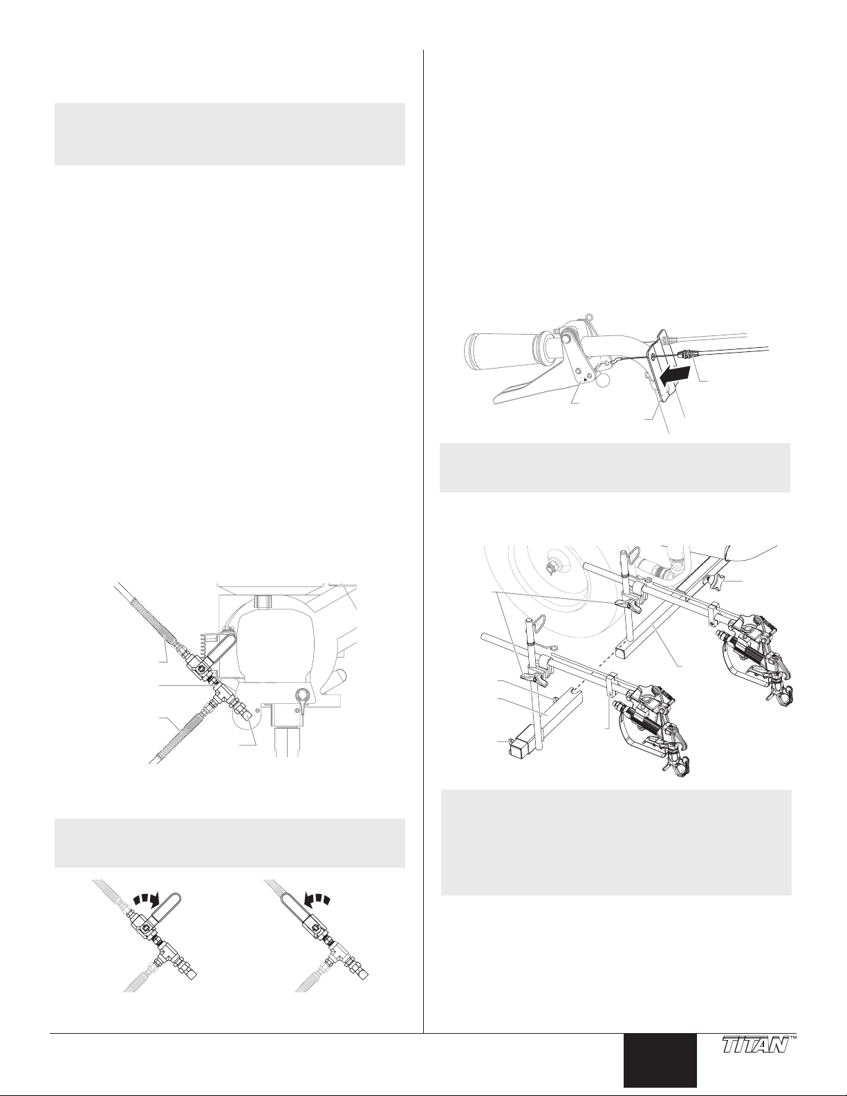
Positioning the spray guns (both units)
1. Loosen the support bar knob and slide the gun support bar
to the desired horizontal position. Make sure the gun is far
enough away from the cart so that the rear wheel does not
track over the fresh spray pattern.
2. 2nd Gun Mounting (if equipped) -
a. Slide the 2nd gun support bar assembly over the end of the 1st gun
b. Loosen the 2nd gun post knob and slide the post to the desired
c. Run the 2nd gun cable through the block and cable guides,
IMPORTANT: Make sure the cable is not touching the tires or
interfering with the mobility of the cart in any way.
d. Insert the gun cable assembly into the hole of the control guide
e. Attach the hooked end of the cable into the hole of the lever plate.
3. Loosen the gun riser clamp(s) and slide the spray gun(s) to the
support bar. Secure in place by tightening the 2nd gun support
bar knob.
horizontal position.
underneath the frame and back towards the cart handle. Use the
tie wraps to secure the cable to the frame.
until it snaps into place.
Gun cable
Lever plate
Control guide
NOTE: See the “Adjusting the Trigger Tension” section in
order to verify that the cable is installed properly.
desired vertical position(s). A distance of 6” from the tip to the
spray surface is a good starting point.
Gun riser
clamps
Support
bar knob
6’ hose
Valve
assembly
50’ hose
Outlet
3. Attach an airless spray gun to each of the spray hoses. Using
two wrenches (one on the gun and one on the hose), tighten
securely.
NOTE: If you plan on using both guns, make sure the valve
handle is in the open position (handle is in line with
the 6’ hose)
Valve
closed
© Titan Tool Inc. All rights reserved. 5
Valve
open
Gun
Knob
2nd gun
t bar
2nd gun
post knob
Block
support
bar
NOTE: The gun support bar and the spray gun(s) can be
mounted on either side of the sprayer. Refer to the
“Spray Gun Positions” illustration near the back of
this manual.
NOTE: The height of the spray gun aects the width of the
spray pattern (i.e., the lower the gun, the smaller
the line width). Tip size also aects line width.
English
Page 6

Trigger Selector (Two-Gun units)
locked position.
ON/OFF
1. Set the trigger selector for proper spray gun operation. The
gun lever on the right handlebar triggers the gun or guns.
The selector on the trigger must be set for the rst gun, both
guns, or the second gun .
IMPORTANT: Always turn the trigger lock on the spray gun to
the locked position before making any adjustments to the trigger
selector. Also, release the trigger cable from its block by lifting
the cable up and out of the block. There will be a brief triggering
of the gun while releasing the trigger cable.
a. First Gun — The rst gun
position is with the selector
in the left position. Push the
lever toward the inside of the
frame until the pin engages
the left plate.
b. Both Guns — The dual gun
position is with the selector
in the center position. Push
the lever toward the center
position until the pin engages
both plates. The pin must
engage both plates.
c. Second Gun — The second
gun position is with the
selector in the right position.
Push the lever away from the
inside of the frame until the
pin engages the right plate.
Preparing a New Sprayer
If this unit is new, it is shipped with test uid in the uid section to
prevent corrosion during shipment and storage. This uid must be
thoroughly cleaned out of the system with mineral spirits before you
begin spraying.
IMPORTANT: Always keep the trigger lock
on the spray gun in the locked position
while preparing the system.
1. Place the siphon tube into a container
of mineral spirits that has a ash point
of 60ºC (140ºF) or above.
2. Place the return hose into a metal
waste container.
3. Turn the pressure control knob fully
counterclockwise to its lowest pressure
setting.
4. Move the PRIME/SPRAY valve to the
PRIME position.
5. Move the engine ON/OFF switch to the
ON position.
6. Start the engine:
a. Open the fuel valve
lever.
b. Move the throttle lever
to its middle point.
c. Close the engine choke
lever.
d. Holding the frame
with one hand, pull the
starter rope rapidly and
rmly. Continue to hold
the rope as you let it
return. Pull and return
the rope until the engine starts.
7. Turn on the sprayer by moving
the pump ON/OFF switch to
the ON position.
Choke Lever
Fuel Valve
Lever
Sprayer
ON/OFF
Switch
8. Allow the sprayer to run for
15–30 seconds to ush the
test uid out through the
return hose and into the waste
container.
9. Turn o the sprayer by moving
the pump ON/OFF switch to
the OFF position.
Trigger lock in
PRIME
Throttle
Lever
Engine
Switch
Starter Rope
Pressure
Control
Knob
6 © Titan Tool Inc. All rights reserved.
English
Page 7
Preparing to Paint
Before painting, it is important to make sure that the uid in the
system is compatible with the paint that is going to be used.
NOTE: Incompatible uids and paint may cause the valves
IMPORTANT: Always keep the trigger lock on the spray gun in
the locked position while preparing the system.
1. Place the siphon tube into a container of the appropriate
2. Place the return hose into a metal waste container.
3. Turn the pressure control knob fully counterclockwise to its
4. Move the PRIME/SPRAY valve to the PRIME position.
5. Move the engine ON/OFF switch to the ON position.
6. Start the engine:
a. Open the fuel valve
b. Move the throttle lever
c. Close the engine choke
d. Holding the frame
7. Turn on the sprayer by moving
8. Allow the sprayer to run for
9. Turn o the sprayer by moving
NOTE: Make sure that the spray gun does not have a tip or
10. Move the PRIME/SPRAY valve to the SPRAY position.
11. Turn on the sprayer.
12. Turn the pressure control knob slowly clockwise to increase
13. Unlock the gun by turning the gun trigger lock to the
14. Trigger the gun into the metal waste container until the old
15. Lock the gun by turning the gun trigger lock to the locked
16. Set down the gun and increase the pressure by turning the
17. Check the entire system for leaks. If leaks occur, turn the
20. Follow the “Pressure Relief Procedure” in this manual before
© Titan Tool Inc. All rights reserved. 7
to become stuck closed, which would require
disassembly and cleaning of the sprayer’s uid
section.
solvent for the material being sprayed (refer to
recommendations of the material manufacturer). An example
of the appropriate solvent is water for latex paint.
lowest pressure setting.
Throttle
Lever
Engine
ON/OFF
Switch
Starter Rope
Pressure
Control
Knob
lever.
to its middle point.
lever.
with one hand, pull the
starter rope rapidly and
rmly. Continue to hold
the rope as you let it
return. Pull and return
the rope until the engine starts.
the pump ON/OFF switch to
the ON position.
Choke Lever
Fuel Valve
Lever
ON/OFF
Sprayer
Switch
15–30 seconds to ush the old
solvent out through the return
hose and into the metal waste
container.
the pump ON/OFF switch to
the OFF position.
tip guard installed.
pressure.
unlocked position.
Ground the gun by holding it against
the edge of the metal container
while flushing. Failure to do so may
lead to a static electric discharge,
which may cause a fire.
solvent is gone and fresh solvent is coming out of the gun.
position.
pressure control knob slowly clockwise to its highest setting.
sprayer o and follow the “Pressure Relief Procedure” in this
manual before tightening any ttings or hoses.
changing from solvent to paint.
Be sure to follow the Pressure Relief Procedure when
shutting the unit down for any purpose, including
servicing or adjusting any part of the spray system,
changing or cleaning spray tips, or preparing for
cleanup.
Painting
1. Place the siphon tube into a container of paint.
2. Place the return hose into a metal waste container.
3. Turn the pressure control knob fully counterclockwise to its
lowest pressure setting.
4. Move the PRIME/SPRAY valve to the
PRIME position.
5. Move the engine ON/OFF switch to the
ON position.
PRIME
6. Start the engine:
a. Open the fuel valve lever.
b. Move the throttle lever to its middle point.
c. Close the engine choke lever.
d. Holding the frame with one hand, pull the starter rope rapidly
and rmly. Continue to hold the rope as you let it return. Pull and
return the rope until the engine starts.
7. Turn on the sprayer by moving the pump ON/OFF switch to
the ON position.
8. Allow the sprayer to run until paint is coming through the
return hose into the metal waste container.
9. Turn o the sprayer by moving the pump ON/OFF switch to
the OFF position.
10. Remove the return hose from the waste container and place it in
its operating position above the container of paint.
11. Move the PRIME/SPRAY valve to the
SPRAY position.
12. Turn on the sprayer.
13. Turn the pressure control knob slowly
SPRAY
clockwise to increase pressure.
14. Unlock the gun by turning the gun trigger lock to the
unlocked position.
Ground the gun by holding it against
the edge of the metal container
while flushing. Failure to do so may
lead to a static electric discharge,
which may cause a fire.
15. Trigger the gun into the metal waste container until all air and
solvent is ushed from the spray hose and paint is owing
freely from the gun.
16. Lock the gun by turning the gun trigger lock to the locked
position.
17. Turn the pressure control knob fully counterclockwise to its
lowest setting.
18. Turn o the sprayer.
19. Attach tip guard and tip to the gun as instructed by the tip
guard or tip manuals.
POSSIBLE INJECTION HAZARD. Do not spray without
the tip guard in place. Never trigger the gun unless
the tip is in either the spray or the unclog position.
Always engage the gun trigger lock before removing,
replacing or cleaning tip.
20. Turn on the sprayer.
21. Increase the pressure by turning the pressure control knob
slowly clockwise. Test the spray pattern and line position on a
long piece of roong felt or cardboard.
a. Adjust the pressure control knob until the spray from the gun is
completely atomized. Try to keep the pressure control knob at the
lowest setting that maintains good atomization.
English
Page 8
NOTE: Turning the pressure up higher than needed to
atomize the paint will cause premature tip wear and
additional overspray.
b. Check for proper line width and position. If adjustment to the
position of the spray gun is required, refer to the “Setup” procedure
earlier in this section.
22. Make sure that the spray gun completely shuts o when the
gun trigger is released. If adjustment to the trigger tension
is required, refer to the “Adjusting the Trigger Tension”
procedure.
Operating the Front Caster
The front caster on the cart is designed to track the sprayer in either
a straight line or allow free motion. Standing behind the sprayer, the
trigger on the left handle of the cart controls the operation of the
front caster.
1. To lock the front caster in the straight line position, squeeze
then release the caster trigger and move the sprayer forward.
2. To allow free motion of the front caster, squeeze and hold the
caster trigger.
NOTE: To lock the front caster in free motion mode,
squeeze and hold the caster trigger and then push
in the locking button on the side of the trigger.
Once the locking button is pushed in, the caster
trigger can be released. To release the locking pin,
squeeze the caster trigger.
Pressure Relief Procedure
Be sure to follow the Pressure Relief Procedure when
shutting the unit down for any purpose, including
servicing or adjusting any part of the spray system,
changing or cleaning spray nozzles, or preparing for
cleanup.
1. Lock the gun by turning the gun trigger lock to the locked
position.
2. Turn o the sprayer by moving the pump ON/OFF switch to
the OFF position.
3. Turn o the engine by moving the engine ON/OFF switch to
the OFF position.
4. Turn the pressure control knob counterclockwise to its lowest
setting.
5. Unlock the gun by turning the gun trigger lock to the
unlocked position.
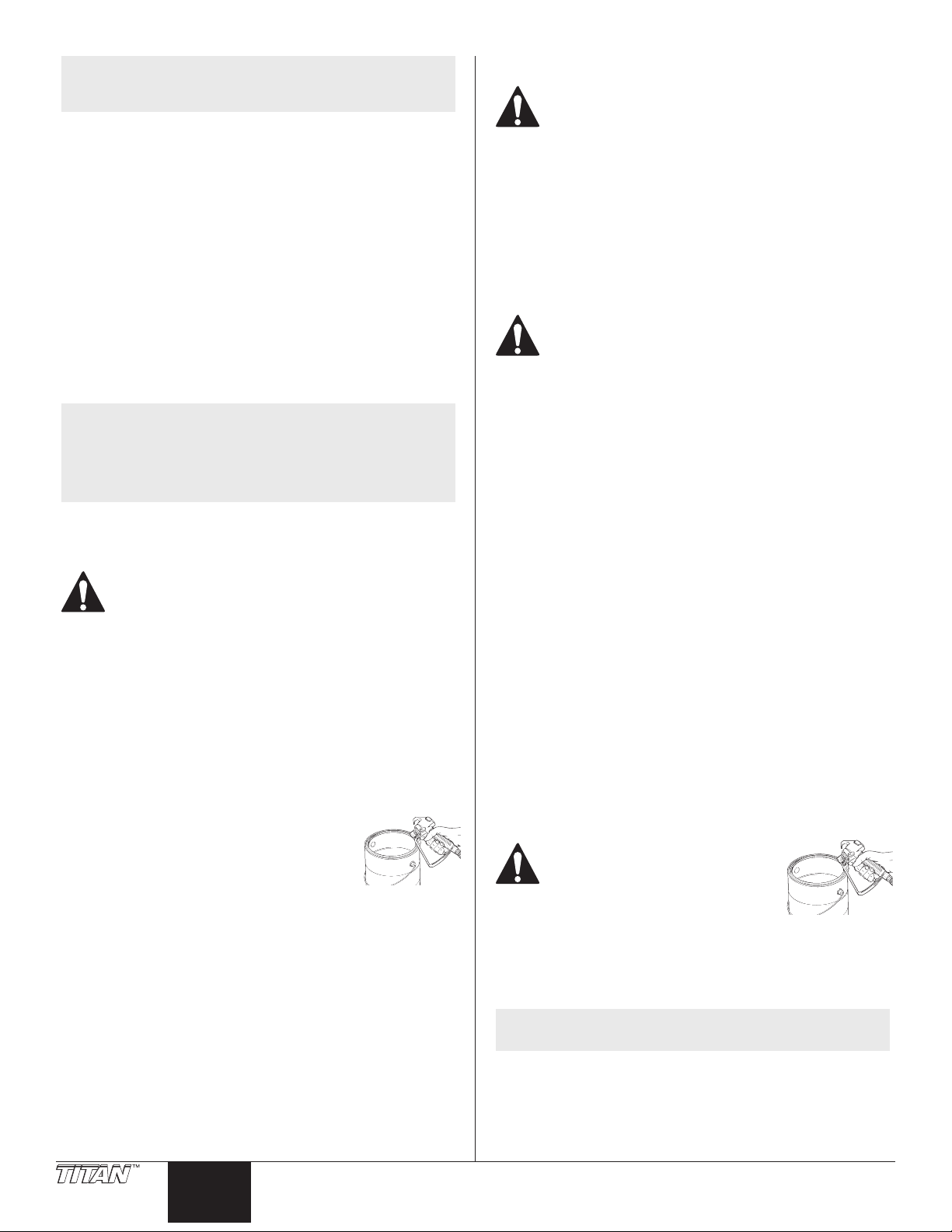
6. Hold the metal part of the gun rmly to the
side of a metal container to ground the gun
and avoid a build up of static electricity.
7. Trigger the gun to remove any pressure that
may still be in the hose.
8. Lock the gun by turning the gun trigger lock to the locked
position.
9. Move the PRIME/SPRAY valve to the PRIME position.
Cleanup
Special cleanup instructions for use with flammable
solvents:
• Always ush spray gun preferably outside and at least one
hose length from spray pump.
• If collecting ushed solvents in a one gallon metal container,
place it into an empty ve gallon container, then ush
solvents.
• Area must be free of ammable vapors.
• Follow all cleanup instructions.
IMPORTANT: The sprayer, hose, and gun should be cleaned
thoroughly after daily use. Failure to do so permits material to
build up, seriously affecting the performance of the unit.
Always spray at minimum pressure with the gun
nozzle tip removed when using mineral spirits or any
other solvent to clean the sprayer, hose, or gun. Static
electricity buildup may result in a fire or explosion in
the presence of flammable vapors.
1. Follow the “Pressure Relief Procedure” found in the Operation
section of this manual.
2. Remove the gun tip and tip guard and clean with a brush
using the appropriate solvent.
3. Place the siphon tube into a container of the appropriate
solvent (refer to recommendations of the material
manufacturer). An example of the appropriate solvent is
water for latex paint.
4. Place the return hose into a metal waste container.
5. Move the PRIME/SPRAY valve to its PRIME position.
6. Move the engine ON/OFF switch to the ON position and start
the engine.
7. Turn on the sprayer by moving the sprayer ON/OFF switch to
the ON position.
8. Slowly turn the pressure control knob clockwise to increase
the pressure until uid starts to come out of the return hose.
9. Allow the solvent to circulate through the sprayer and
ush the paint out of the return hose into the metal waste
container.
10. Turn the pressure control knob fully counterclockwise to its
lowest setting.
11. Turn o the sprayer by moving the ON/OFF switch to the OFF
position.
12. Move the PRIME/SPRAY valve to its SPRAY position.
13. Turn on the sprayer.
14. Turn the pressure control knob slowly clockwise to increase
pressure.
Ground the gun by holding it against
the edge of the metal container
while flushing. Failure to do so may
lead to a static electric discharge,
which may cause a fire.
15. Trigger the gun into the metal waste container until the paint
is ushed out of the hose and solvent is coming out of the
gun.
16. Continue to trigger the spray gun into the waste container
until the solvent coming out of the gun is clean.
NOTE: For long-term or cold weather storage, pump
17. Follow the “Pressure Relief Procedure” found in the Operation
18. Store the sprayer in a clean, dry area.
IMPORTANT: Do not store the unit under pressure.
8 © Titan Tool Inc. All rights reserved.
English
mineral sprits through the entire system.
section of this manual.
Page 9

Cleaning the Spray Tip
1. Flush the gun with solvent immediately after the work is
completed.
2. Oil the sliding pins to prevent them from seizing up.
Should the spray tip become clogged,
reverse the spray tip with the lever and pull
the trigger. Once the obstruction comes out
of the spray tip, release the trigger, reverse
the spray tip back to the spray pattern
setting, and resume spraying.
Do not attempt to clean the tip
with your finger.
Do not use a needle or other
sharp pointed instrument
to clean the tip. The hard
tungsten carbide is brittle and
can be chipped.
Maintenance
Before proceeding, follow the Pressure Relief
Procedure outlined previously in this manual.
Additionally, follow all other warnings to reduce the
risk of an injection injury, injury from moving parts or
electric shock.
Maintaining the Engine
When transporting a sprayer with a gas engine, make
sure the fuel is shut off.
NOTE: For detailed engine specications and maintenance,
refer to the separate engine manual supplied with
this sprayer.
Important Facts Concerning this Sprayer
This gas-powered sprayer contains a clutch that engages when
the sprayer is pumping. The sprayer’s pressure control system
engages and disengages the clutch to control pressure. To prevent
unnecessary wear to the clutch, it is advisable to adjust the engine
speed and pressure setting to limit the amount of times the clutch
engages and disengages. To reduce clutch wear, refer to the
following examples.
Example:
Operating one gun with a .019” tip — reduce the engine speed
by adjusting the throttle to a low or medium setting and increase
pressure only until the heavy ends of the spray pattern have been
eliminated.
Example:
Operating one gun with .025” tip — increase engine speed to a
higher setting and increase pressure until the heavy ends of the spray
pattern have been eliminated.
NOTE: All Honda engine work should be performed by a
Honda authorized service center.
General Repair and Service Notes
The following tools are needed when repairing this sprayer:
Phillips screwdriver 3/8” hex wrench
needle-nose pliers 5/16” hex wrench
adjustable wrench 1/4” hex wrench
rubber mallet 3/16” hex wrench
at-blade screwdriver 1/8” hex wrench
1/2” open-end wrench 7/8” open-end wrench
1. Before repairing any part of the sprayer, read the instructions
carefully, including all warnings.
IMPORTANT: Never pull on a wire to disconnect it. Pulling on a
wire could loosen the connector from the wire.
2. Test your repair before regular operation of the sprayer to be
sure that the problem is corrected. If the sprayer does not
operate properly, review the repair procedure to determine if
everything was done correctly. Refer to the Troubleshooting
section to help identify other possible problems.
3. Make certain that the service area is well ventilated in case
solvents are used during cleaning. Always wear protective
eyewear while servicing. Additional protective equipment
may be required depending on the type of cleaning solvent.
Always contact the supplier of solvents for recommendations.
4. If you have any further questions concerning your Titan airless
sprayer, call Titan:
Technical Service (U.S.) ...................................... 1-800-526-5362
Fax ................................................................. 1-800-528-4826
Example:
Spraying light-bodied materials at low pressure — to reduce surging
at the gun and to decrease clutch wear, reduce the engine speed to
idle and reduce pressure until the desired spray pattern is achieved.
Routine Engine Maintenance
Daily
• Check and ll the gas tank.
• After the rst 20 hours of operation (or 1 month), drain the oil
and rell with clean oil. Check the engine oil level and ll as
necessary.
Weekly
• Remove the cover of the air lter and clean the element.
Replace the element if necessary. If operating in an unusually
dusty environment, check the lter daily and replace if
necessary. (Replacement elements can be purchased from
your local Titan dealer.)
• After each 50 hours (or 3 months) of operation: Change the
engine oil.
Spark Plug
• Use only a (NKG) BPR6ES plug.
• Gap the plug 0.028” – 0.031” (0.7 - 0.8 mm)
• Make sure to use a spark plug wrench when installing and
removing the plug.
© Titan Tool Inc. All rights reserved. 9
English
Page 10
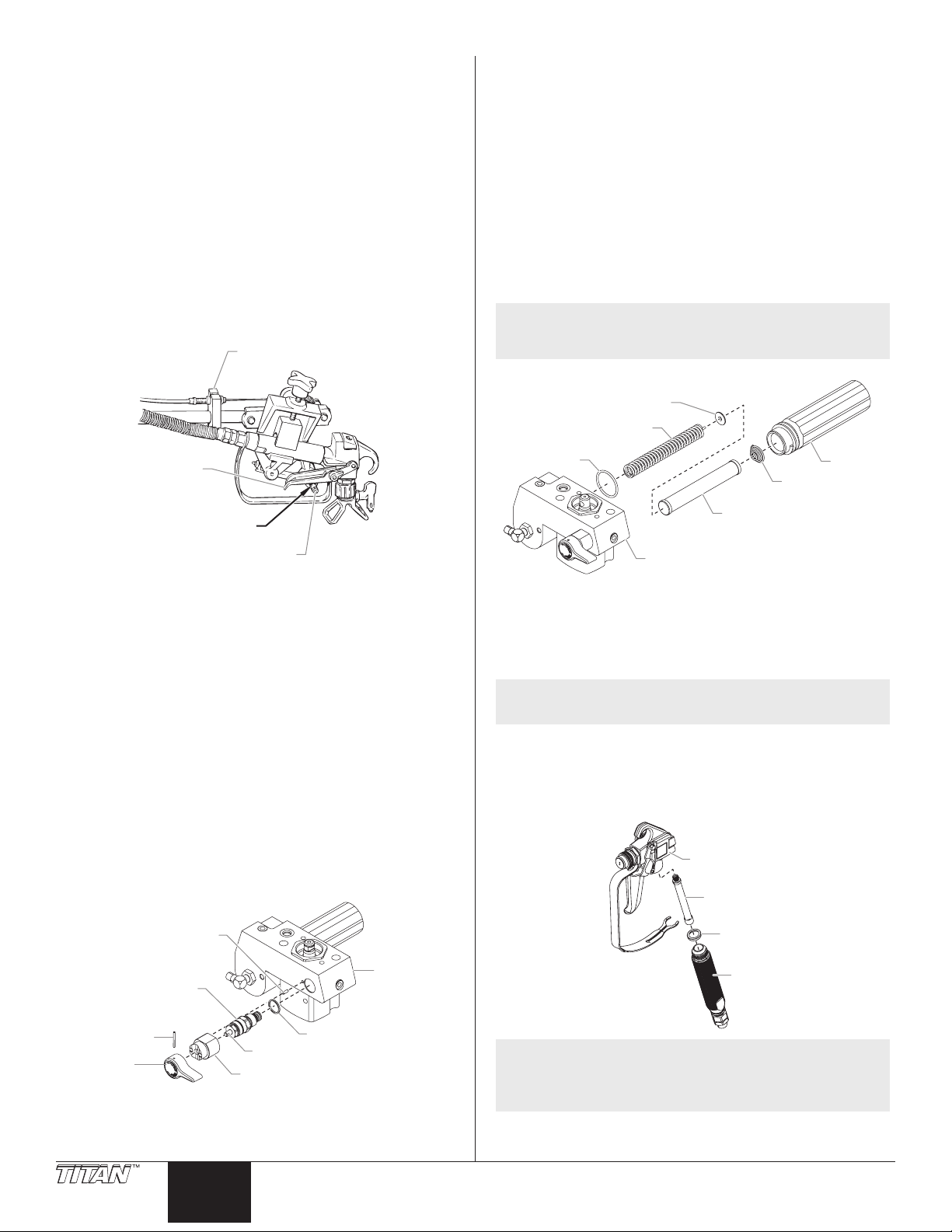
Adjusting the Trigger Tension
Trigger Lever
Cable Block
Groove
old
Handle
Housing
Handle
Use the following procedure to adjust the spring tension of the
trigger lever on the gun holder assembly. The trigger lever pulls and
releases the spray gun trigger when operated from the trigger on the
cart. The proper tension ensures that the gun will shut o when the
gun trigger is released. To ensure proper tension, there should be
approximately a 1/32” to 1/16” gap between the trigger lever and the
spray gun trigger.
IMPORTANT: Always keep the trigger lock on the spray gun in
the locked position while making adjustments to the system.
1. Using a wrench, loosen the bolt on the cable block.
2. Move the cable block in the appropriate direction to create a
gap of 1/32” to 1/16” between the trigger lever and spray gun
trigger.
a. Slide the cable block toward the gun to increase the gap between
the trigger lever and spray gun trigger.
b. Slide the cable block away from the gun to decrease the gap
between the trigger lever and spray gun trigger.
(bolt on back)
Cleaning or Replacing the Filters
Pump Filter
1. Loosen and remove the lter housing by hand. Pull the lter
out of the pump manifold.
2. Slip the lter o of the lter support spring.
3. Inspect the lter. Based on inspection, clean or replace the
lter.
4. Inspect the lter seal. Based on inspection, clean or replace
the lter seal.
5. Slide the new or cleaned lter over the lter support spring
with the adapter in place. Push the lter into the center of the
pump manifold.
6. Slide the lter housing over the lter and thread it into the
pump manifold until secure.
NOTE: The lter housing should be hand-tightened, but
make sure the lter housing is seated fully into the
pump manifold.
Adapter
Filter Support Spring
Spray Gun
Trigger
1/32" to 1/16" Gap
3. Tighten the set screw securely.
Replacing the PRIME/SPRAY Valve
Perform the following procedure using PRIME/SPRAY valve
replacement kit P/N 800-915 or 700-258.
1. Drive the groove pin out of the valve handle.
2. Remove the valve handle and the cam base.
3. Using a wrench, loosen and remove the valve housing
assembly from the pump manifold.
4. Make sure the gasket is in place and thread the new valve
housing assembly into the pump manifold. Tighten securely
with a wrench.
5. Place the cam base over the valve housing assembly.
Lubricate the cam base with grease and line up the cam with
the pump manifold using the dowel pin.
6. Line up the hole on the valve stem with the hole in the valve
handle.
7. Insert the groove pin into the valve handle and through the
valve stem to secure the valve handle in position.
Filter Seal
Filter
Spring
Filter
Pump Manifold
Filter
Gun Filter
1. Move the gun trigger lock to the unlocked position.
2. Loosen and remove the handle from the gun body.
3. Turning clockwise, unscrew the lter from the gun body.
NOTE: Left-handed threads require turning the lter
4. Turning counterclockwise, screw the new or cleaned lter into
5. Make sure the handle seal is in position and thread the handle
6. Move the gun trigger lock to the locked position.
clockwise to remove.
the gun body.
into the gun body until secure.
Gun
Housing
Filter
Dowel Pin
Pump
Valve Housing
Assembly
Pin
Valve
10 © Titan Tool Inc. All rights reserved.
English
Valve Stem
Cam Base
Gasket
Manif
NOTE: For more detail, part number information, and
complete assembly drawings, please see the LX-80II
Professional Airless Gun Owner’s Manual (P/N 313-
2293).
Handle
Seal
Page 11
Assembly
Assembly
Relay
Housing
Gear Housing
Pump Housing Socket Screw
P
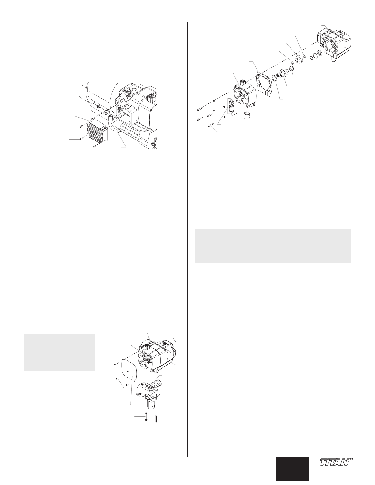
Replacing the Sprayer ON/OFF Switch
1. Perform the Pressure Relief Procedure.
2. Using a Phillips screwdriver, remove the four screws that
secure the heat sink assembly to the housing. Carefully
remove the heat sink assembly from the housing. Gently
move the assembly away from the sprayer and allow the
assembly to hang from the housing.
3. Locate the bottom of the sprayer ON/OFF switch inside the
housing.
ON/OFF
Switch
Heat Sink
Heat Sink
Screw
4. Disconnect the switch wires from the sprayer ON/OFF switch.
Remember the locations of each of the two wires (label the
wires, if necessary).
5. Depress the mounting tabs on each corner of the sprayer ON/
OFF switch inside the housing and remove the switch through
the top of the housing.
6. Snap the new sprayer ON/OFF switch into the switch hole in
the housing.
7. Connect the two switch wires to the new sprayer ON/
OFF switch. Make sure the wires are connected to the
corresponding terminals from which they were removed (refer
to the labels created earlier in this procedure or the electrical
schematic in the Parts List section of this manual).
8. Carefully place the heat sink assembly over the housing taking
care not to pinch any wires.
9. Install the four screws that secure the heat sink assembly to
the housing. Tighten securely.
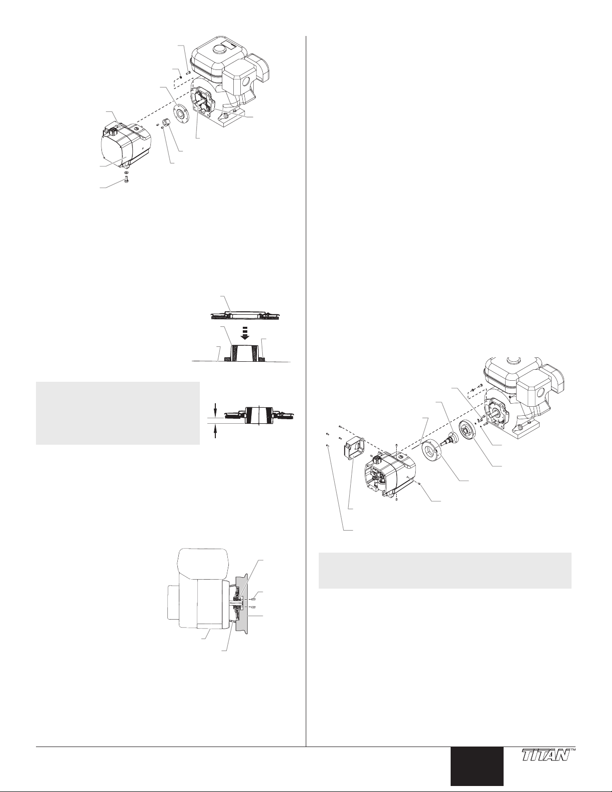
Replacing the Gears and/or Slider Assembly
1. Using a Phillips screwdriver, remove the four front cover
screws. Remove the front cover.
2. Start the engine (refer to the procedures in the Operation
section of this manual). Turn the pressure control knob
clockwise to its maximum pressure setting.
3. Toggle the sprayer ON/OFF switch between the ON and OFF
positions in short bursts until the slider assembly and piston
stop at the bottom of their stroke (in their lowest position).
4. Turn o the engine and perform the Pressure Relief Procedure.
Pump
Front
Front
Cover
Slider
Socket
Screw
Housing
Piston
Fluid
Section
NOTE: If replacing the
slider assembly,
the uid section
Assembly
must be removed
from the pump
housing.
5. Using a 3/8” hex wrench,
remove the two socket
screws that secure the
uid section to the pump
housing.
Cover
Screw
6. Pull uid section housing
down approximately
1/2” from the gear box
housing to clear the
transducer.
7. Slide the uid section housing and piston rod forward until
the piston rod is out of the T-slot on the slider assembly.
8. Using a 1/4” hex wrench,remove the four socket screws that
secure the pump housing to the gear housing.
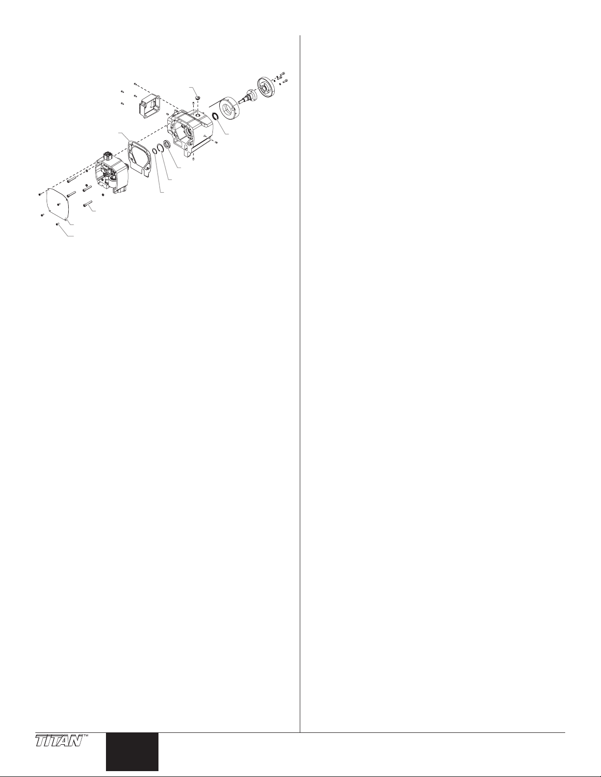
© Titan Tool Inc. All rights reserved. 11
Thrust Washer
Output Gear Assembly
Thrust Washer
Housing Gasket
ump Housing
Cylindrical
Thrust Washer
Crankshaft
Assembly
Thrust
Washer
Slider Bushing
Slider Assembly
9. Slide the pump housing away from the gear housing.
10. Remove and clean the housing gasket. Replace if damaged.
11. Slide the crankshaft assembly, with the two thrust washers out
from the gear housing side of the pump housing.
12. Remove the output gear assembly with the two thrust
washers.
13. Thoroughly clean the crankshaft assembly, the output gear
assembly, and all the thrust washers.
14. Inspect all parts for excessive wear and replace if damaged or
worn. If the crankshaft or output gear assembly are replaced,
replace the corresponding thrust washers as well.
15. Inspect the pinion gear on the end of the drive shaft for wear.
Replace if damaged or worn (refer to the “Servicing the Clutch
Assembly” procedure in this section).
NOTE: If any of the gears are worn and require
replacement, check the grease in the gear housing
for metal particles or shavings. Remove the
contaminated grease. Replace the grease that has
been removed with fresh Lubriplate GR-132 grease.
16. Slide the slider assembly up and out of the slider bushing in
the front of the pump housing.
17. Check the parts for wear.
a. If the slider bushing is scored or out of round the pump housing
should be replaced.
b. If the slider assembly is scored or the connection between the
c. Any parts that will be reused should be cleaned thoroughly, including
connecting rod and slider assembly exhibits movement other than
pivoting movement, the slider assembly should be replaced. The
slider assembly also should be replaced if the connecting rod bearing
shows signs of wear.
the connecting rod. Also, clean the crankshaft pin that the connecting
rod bearing rides on.
18. Coat the output gear assembly and each side of its thrust
washers with fresh Lubriplate GR-132 grease. Place the thrust
washers on their proper shaft of the output gear assembly.
19. Lubricate the output gear assembly with fresh Lubriplate GR132 grease. Insert the gear assembly into its bore in the gear
housing, gear end rst. The teeth on the gear will mate with
the teeth on the drive shaft pinion.
20. Generously coat all surfaces of the cylindrical crankshaft
assembly thrust washer with fresh Lubriplate GR-132 grease.
21. Slip the at end of the cylindrical thrust washer behind the
gear on the output gear assembly, lining its bore up with the
gear housing bearing bore for the crankshaft assembly.
22. Lubricate the crankshaft assembly gear with fresh Lubriplate
GR-132 grease. Slide the gear side shaft of the crankshaft
through the cylindrical thrust washer and into its bore within
the gear housing.
23. Position the pin on the end of the crankshaft towards the bottom
of the gear housing (the bottom dead center position).
English
Page 12
24. Lubricate both faces of the large crankshaft assembly thrust
Pump
Assembly
ansducer
Screw
washer with fresh Lubriplate GR-132 grease. Place the thrust
washer onto the crankshaft against the gear.
25. Place the housing gasket over the gear housing dowel pins.
26. Lubricate the outside of the slider assembly and the inside of
the slider bushing with oil. Fill the slider cup with Lubriplate
1242 grease (the slider cup is the area on the slider assembly
where the connecting rod and slider join and pivot).
27. Insert the slider assembly into the slider bushing.
28. Carefully place the pump housing assembly in front of the
gear housing assembly, lining up the gear housing dowel pins
with their corresponding holes in the pump housing. Slide
the pump housing onto the gear housing until there is no gap
between the housings and gasket.
NOTE: While sliding the pump housing into place, the
crankshaft pin will begin to protrude from the
bearing in the center of the pump housing. Position
the slider assembly so that as the crankshaft pin
protrudes from the main bearing, it engages the
connecting rod bearing.
IMPORTANT: Do not force the pump housing and gear housing
together.
29. Locate the four socket screws and lock washers that secure
the pump housing to the gear housing.
30. Using a 1/4” hex wrench, snug and tighten the socket screws
in a crossing pattern. Torque to 200–230 in.-lbs.
31. Slide the top of the piston rod into the T-slot on the slider
assembly.
32. Position the pump block underneath the gear box housing
and push up until it rests against the gear box housing.
33. Insert the two socket screws that secure the uid section to
the pump housing and alternately snug, tighten, and torque
the screws to 400-440 in.-lbs.
34. Position the front cover over the pump housing. Secure the
front cover using the four front cover screws.
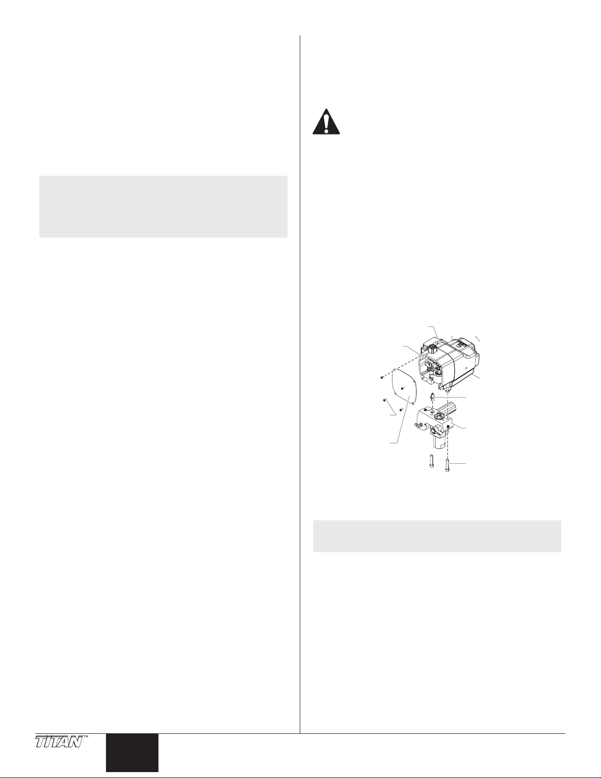
Replacing the Transducer
1. Loosen and remove the four front cover screws. Remove the
front cover.
2. Stop the sprayer at the bottom of its stroke so that the piston
is at its lowest position.
3. Perform the Pressure Relief Procedure.
Before proceeding, follow the Pressure Relief
Procedure outlined previously in this manual.
Additionally, follow all other warnings to reduce the
risk of an injection injury, injury from moving parts or
electric shock.
4. Tilt the sprayer back for easy access to the uid section.
5. Using a 3/8” hex wrench, loosen and remove the two socket
screws.
6. Pull the uid section down approximately 1/2” from the
housing to clear the transducer.
7. Slide the uid section and piston rod forward until the piston
rod is out of the T-slot on the connecting rod.
8. Using a wrench, remove the transducer assembly from the
uid section.
9. Thread the new transducer assembly from the uid section.
Tighten securely with a wrench.
10. Reassemble the pump by reversing steps 1-8.
IMPORTANT: Make sure the transducer is aligned properly
with the hole in the fluid section during reassembly. Improper
alignment may cause damage to the transducer O-ring.
Housing
Slider
Tr
Front
Cover
Screw
Front
Cover
Assembly
Fluid
Section
Housing
Socket
Servicing the Clutch Assembly
NOTE: When replacing the clutch armature, the clutch rotor
Removing/Replacing the Clutch Armature Assembly
1. Perform the Pressure Relief Procedure.
2. Locate the wire that exits the rear of the pressure control
12 © Titan Tool Inc. All rights reserved.
English
3. Using a 12 point, 5/16” wrench, remove the four screws
4. Using a 9/16” socket, remove the screw that secures the gear
5. Slide the pump and gear housings away from the engine to
must be replaced also. This will allow for even wear
and maximum life on clutch parts.
housing and connects to the wire harness on the engine.
Disconnect this wire from its connector at the engine wire
harness.
and lock washers that secure the clutch housing to the gear
housing.
housing to the cart.
disengage them from the clutch housing.
Page 13
Gear Housing
Screw
Clutch Housing
Housing
Clutch
Armatur
Bushing
Assembly Screw
Hex Screw
Lock Washer
Clutch Armature
Gear
Housing
Clutch
Engine Shaft
Taper Lock Bushing
Pump
Set Screw
Housing
6. Locate the clutch armature assembly on the end of the engine
shaft. Note the two set screws as well as the unused, threaded
hole in the taper lock bushing at the center of the clutch hub.
7. Using an 1/8” hex wrench, remove the two set screws from the
taper lock bushing
8. Thread one of the set screws into the unused, threaded hole
on the taper lock bushing. As the screw tightens, the bushing
will loosen. Once the bushing has loosened enough, slide the
clutch armature assembly o the engine shaft.
9. Before replacing the clutch
hub and armature assembly
the proper “set back” must be
created. Using the hub set-up
tool (P/N 0555926), create a
“set back” of 0.10” between the
friction surface of the clutch
armature and the forward face
of the clutch hub.
Clutch
Hub
Flat
Surface
e
Set-Up
Tool
Removing the Clutch Rotor, Clutch Field, and Drive Shaft
Assembly
1. Follow steps 1–7 in “Removing/Replacing the Clutch Armature
Assembly.”
2. Locate the clutch rotor assembly, which will be inside the
rear the gear housing. Note the locations of the three socket
screws and the two empty, threaded holes on the clutch rotor.
3. Using a 3/16” hex wrench, remove the three socket screws
and lock washers that secure the clutch rotor to the drive shaft
assembly.
4. Thread two of the socket screws into the empty, threaded
holes and tighten alternately. This will push the clutch rotor
away from the drive shaft assembly and pinion.
5. Using a Phillips screwdriver, remove the four screws that
secure the heat sink assembly to the housing. Carefully
remove the heat sink assembly from the housing.
6. Locate the two clutch eld wires that pass from the gear
housing into the control housing through a hole in the back
of the control housing. Remember the wire connection
terminals on the relay assembly (label if necessary) and
disconnect the wires. Gently move the heat sink assembly
away from the housing and rest it on the work surface by the
control housing.
7. Locate the four pairs of set screws that secure the clutch eld
to the gear housing. They are located on the exterior of the
gear housing at the 12, 3, 6, and 9 o’clock positions while
facing the clutch eld end of the gear housing. Using an 1/8”
hex wrench, remove the setscrews. Remember the location
of the two clutch eld wires with respect to the grommet and
EPC housing.
8. Carefully slide the clutch eld out of the gear housing, keeping
the eld square to the gear housing so it does not bind.
NOTE: A new clutch hub and
10. To replace the clutch armature assembly , line up the three
11. Line up the key on the taper lock bushing with the keyway on
12. Apply blue Loctite to the two set screws and insert the screws
13. Using the clutch set-up tool
14. While holding the clutch armature assembly against the tool,
15. Make sure the friction surface of the clutch armature is clean
armature assembly will come
pre-assembled, but the “set
back” may not be correct. The
“set back” must still be created
using the hub set-up tool.
holes in the taper lock bushing with the three holes in the
clutch armature and insert the bushing into the center of the
clutch armature.
the engine shaft and slide the assembly onto the shaft with
the holes facing out.
into the taper lock bushing. Tighten the set screws only two
turns at this time.
(P/N 0555926), position
the clutch armature on
the engine shaft. Hold the
tool across the face of the
clutch housing so that the
center, recessed portion
of the tool straddles the
clutch armature assembly.
Pull the clutch armature
assembly towards the
tool until the face of the
armature is against the
tool.
use an 1/8” hex wrench and alternately tighten the set screws
into the taper lock bushing. Torque to 65–75 in-lbs.
and free from oil or grease.
Engine
0.10"
Taper
Lock
Set
Screw
Set-Up
Tool
Clutch
Housing
Clutch Rotor Socket Screw
Drive Shaft Assembly
Clutch Field Wires
Lock
Washer
Clutch
Clutch
Field Assembly
Heat Sink
Assembly
Heat Sink
NOTE: To remove the drive shaft assembly, the pump
housing rst must be removed from the gear
housing.
9. Using a Phillips screwdriver, remove the four front cover
screws. Remove the front cover.
10. Using a 1/4” hex wrench, remove the four socket screws that
secure the pump housing to the gear housing.
11. Slide the pump housing away from the gear housing.
12. Remove and clean the housing gasket. Replace if damaged.
13. Locate the drive shaft pinion that is protruding from the front
side of the gear housing. Remove the small snap ring that is
located on the drive shaft hub in front of the ball bearing that
is supporting the drive shaft.
14. From the opposite side of the gear housing (clutch side) slide
the drive shaft assembly out of the gear housing.
15. Inspect the grease seal located inside the bore from which
the drive shaft was removed. Replace if worn or damaged.
Set Screw
Rotor
© Titan Tool Inc. All rights reserved. 13
English
Page 14
To remove the grease seal, use a at blade screwdriver to
Front Cover Screw
carefully pry the seal from the bore.
16. Clean the inside of the gear housing.
Plug
Housing Gasket
Bearing
Snap Ring
Small Snap Ring
Pump Housing Socket Screw
Front Cover
Grease Seal
Installing the Clutch Rotor Assembly, Clutch Field and
Drive Shaft Assembly
1. If the drive shaft grease seal was removed, press a new seal
into the bore from which the old seal was removed.
2. From the clutch side of the gear housing, insert the drive shaft
assembly into the bore, through the grease seal, and through the
ball bearing on the gear side of the gear housing.
3. From the gear side of the gear housing, insert the snap ring
into the groove on the drive shaft hub in front of the ball
bearing.
4. Place the housing gasket over the gear housing dowel pins.
5. Carefully place the pump housing assembly in front of the
gear housing assembly, lining up the gear housing dowel pins
with their corresponding holes in the pump housing. Slide
the pump housing onto the gear housing until there is no gap
between the housings and gasket.
IMPORTANT: Do not force the pump housing and gear housing
together.
6. Locate the four socket screws and lock washers that secure
the pump housing to the gear housing.
7. Using a 1/4” hex wrench, snug and tighten the socket screws
in a crossing pattern. Torque to 200–230 in.-lbs.
8. Line up the four holes around the outside of the clutch eld
with the four set screw holes in the gear housing. The clutch
eld wires should be at approximately the 1 or 2 o’clock
position.
9. Route the two clutch eld wires through the hole and into the
control housing.
10. Carefully slide the clutch eld into its bore in the gear housing
until it “bottoms out” within the housing. Do not pinch the
clutch eld wires during installation.
11. Thread one of the pointed set screws into its hole. Using an
1/8” hex wrench, rotate the screw slowly until it contacts the
clutch eld. Do not tighten the set screw. The tip of the set
screw should mate with the drill point hole in the eld. Check
the clutch eld for rotation. If it rotates within its bore, the set
screw is not seated within the drill point.
12. When the set screw is properly seated, install the remaining
three pointed set screws. Do not tighten the set screws.
13. Using a crossing pattern, tighten each of the pointed
setscrews until they are snug. Once all four pointed set screws
are snug, use a crossing pattern to tighten and torque the set
screws to 70–80 in.-lbs.
IMPORTANT: It is very important to evenly snug, tighten, and
torque the clutch field pointed set screws in a crossing pattern.
This ensures the clutch field will stay centered in the gear
housing.
15. Line up the three screw holes and dowel pin hole on the
clutch rotor with the screw holes and dowel pin on the drive
shaft assembly hub. Place the clutch rotor onto the hub.
16. Using a 3/16” hex wrench, thread the three socket screws and
lock washers through the clutch rotor and into the drive shaft
assembly hub. Evenly snug, tighten, and torque the socket
screws to 75–85 in-lbs.
17. Make sure the friction surface of the clutch rotor is clean and
free from oil or grease.
18. Locate the two clutch eld wires in the control housing.
Gently pull the wires fully into the EPC housing so that there
is no slack in the gear housing. Connect the wires to their
proper terminals on the relay (refer to the labels created
earlier in this procedure or the electrical schematic in the Parts
List section of this manual).
19. Carefully place the heat sink assembly over the control
housing taking care not to pinch any wires.
20. Install the four screws that secure the heat sink assembly to
the control housing. Tighten securely.
Mating the Gear Housing and the Clutch Housing
1. Place the gear housing assembly onto the cart in front of the
clutch housing. Line up the dowel pins in the gear housing
with their corresponding holes in the clutch housing. Slide
the gear housing assembly onto the clutch housing until there
is no gap between the housings.
2. Thread the four hex screws and lock washers through the
clutch housing and into the gear housing.
3. Using a 12 point, 5/16” wrench, snug and tighten the hex
screws in a crossing pattern. Torque to 140–155 in.-lbs.
4. Using a 9/16” socket, thread the hex screw that secures the
gear housing to the cart through the underside of the cart and
into the gear housing. Torque to 100–120 in.-lbs.
5. Connect the wire from the EPC housing to its mating
connector on the engine wire harness.
Checking the Clutch Gap
1. Remove the plastic plug from the top of the clutch housing.
Look through the port to locate the clutch armature and the
clutch rotor.
2. Check the gap between the clutch armature and the clutch
rotor using a .016” feeler gauge and a .035” feeler gauge.
a. Insert each feeler gauge through the port and into the gap
between the clutch armature and the clutch rotor. The .016”
feeler gauge should t in the gap. The .035” feeler gauge
should not t in the gap.
b. Pull the engine pull cord several times to rotate the clutch
armature, checking the gap with each feeler gauge between
each pull.
c. If the .016” gauge does not t or the .035” gauge does t at
any checkpoint, the gap must be readjusted. This is done
by relocating the clutch hub and armature assembly on the
engine shaft. Refer to the “Removing/Replacing the Clutch
Armature Assembly” procedure.
14 © Titan Tool Inc. All rights reserved.
English
Page 15

Servicing the Fluid Section
alve Seat
retainer
old
Use the following procedures to service the valves and repack the
uid section.
1. Using a Phillips screwdriver, remove the four front cover
screws. Remove the front cover.
2. Start the engine (refer to the procedures in the Operation
section of this manual). Turn the pressure control knob
clockwise to its maximum pressure setting.
3. Toggle the sprayer ON/OFF switch between the ON and
OFF positions in short bursts until the slider assembly and
piston rod stop at the bottom of their stroke (in their lowest
position).
4. Turn o the engine and perform the Pressure Relief
Procedure.
Before proceeding, follow the Pressure Relief
Procedure outlined previously in this manual.
Additionally, follow all other warnings to reduce the
risk of an injection injury, injury from moving parts or
electric shock.
Servicing the Valves
The design of the uid section allows
access to the inlet valve and seat
as well as the outlet valve and seat
without completely disassembling
the uid section. It is possible that
the valves may not seat properly
because of debris stuck in the inlet
valve seat or outlet valve seat. Use
the following instructions to clean
the valves and reverse or replace the
seats.
NOTE: Keep the sprayer in the
upright position for this
procedure.
1. Using a wrench, loosen and remove the inlet valve housing
from the uid section housing.
2. Clean out any debris in the inlet valve housing and examine
the valve housing and seat. If the inlet valve seat is damaged,
reverse the seat to the unused side or replace the seat.
NOTE: If the inlet valve seat is reversed or replaced, the
inlet valve ball must be replaced.
3. Using a 3/8” hex wrench, loosen and remove the outlet valve
retainer from the piston rod.
NOTE: Always service the outlet
valve with the piston rod
attached to the pump. This
will prevent the piston
rod from rotating during
disassembly of the outlet
valve.
4. Clean out any debris and examine
the outlet valve retainer and seat.
If the outlet valve seat is damaged,
reverse to the unused side or
replace the seat.
NOTE: If the outlet valve seat is reversed or replaced, the
outlet valve ball must be replaced.
5. Remove, clean, and inspect the outlet cage and outlet valve
ball. Replace if they are worn or damaged.
6. Reassemble the valves by reversing the steps above. Apply
blue Loctite (P/N 426-051) to male threads of inlet valve
housing and torque to 450-500 in-lbs.
Fluid Section
Housing
Piston Bushing
Inlet Valve Seal
Inlet Cage
Inlet Valve Ball
Inlet V
PTFE O-Ring
Inlet Valve
Housing
Piston rod
Upper seal
Upper cage
Outlet valve
ball
Lower seal
Outlet valve
seat
Outlet valve
Repacking the Fluid Section
1. Remove the foot valve assembly using the steps in the
“Servicing the Valves” procedure above.
NOTE: The outlet valve does not need to be disassembled
2. Using 3/8” a hex wrench, loosen and remove the two pump
3. Pull the pump block down approximately 1/2” from the gear
4. Slide the pump block and piston rod forward until the piston
5. Slide the piston rod out through the bottom of the pump
6. Loosen and remove the retainer nut and piston guide from
7. Remove the upper and lower packings from the pump block.
8. Clean the pump block.
9. Locate the new upper and lower packings and pack the areas
10. Inspect the piston rod for wear and replace if necessary.
11. Insert the upper packing into the top of the pump block with
12. Insert the piston guide into the retainer nut. Thread the
13. Pre-form the lower packing using the lower packing sizing
14. Insert the lower packing partially into the bottom of the pump
15. Push the lower packing into position using the lower packing
16. Inspect the piston rod for wear and replace if necessary.
from the piston rod for this procedure.
Retainer Nut
Piston Guide
Upper Packing
Assembly
Pump Manif
Pump
Manifold
Mounting
Screw
Lower Packing
Assembly
Piston Rod
block mounting screws.
box housing.
rod is out of the T-slot on the slider assembly.
block
the pump block.
between the packing lips with grease. Lubricate the o-rings
on the exterior of the packings with grease.
the raised lip on the packing facing down.
retainer nut into the pump block until it is hand tight.
tool (included in the repacking kit).
block so that the side that has the o-ring closest to the face of
the packing faces up.
Install upper packing
with raised lip
facing down.
Raised Lip
Install lower packing
with large beveled
edge facing up.
Large Beveled Edge
insertion tool (see Fluid Section Assembly parts list for lower
packing insertion tool P/N).
© Titan Tool Inc. All rights reserved. 15
English
Page 16

NOTE: Coat the piston guide tool and the piston rod with
17. Place the piston insertion tool (included in the repacking kit)
18. Insert the piston rod into the bottom of the pump block,
grease before inserting them into the pump block.
over the top of the piston rod.
through the lower packing, through the upper packing, and
out through the retainer nut. Using a rubber mallet, tap the
bottom of the piston rod lightly until the piston rod is in
position in the pump block.
NOTE: When repacking the uid section, make sure the
19. Remove the piston insertion tool from the top of the piston
20. Using a wrench, tighten the retainer nut into the pump block.
21. Slide the top of the piston rod into the T-slot on the slider
22. Position the pump block underneath the gear box housing
IMPORTANT: Make sure the transducer is aligned properly
with the hole in the pump block during reassembly. Improper
alignment may cause damage to the transducer gasket.
23. Thread the pump block mounting screws through the pump
24. Reassemble the inlet valve assembly into the pump block.
NOTE: During reassembly, make sure the o-ring between
25. Reassemble suction set to uid section. If swivel is removed
raised lip on the bottom of the lower packing is fully
outside the packing around the piston rod after
insertion of the piston rod.
rod.
Torque to 300-360 in. lbs.
assembly.
and push up until it rests against the gear box housing.
block and into the gear box housing. Torque to 400-440 in.
lbs.
Apply blue Loctite (P/N 426-051) to male threads of inlet valve
housing and torque to 450-500 in-lbs.
the pump block and inlet valve housing is
lubricated with grease and in position.
from the inlet valve housing, add blue Loctite (P/N 426-051) to
male threads. Replace the return hose into the clamp on the
siphon tube.
NOTE: When adjusting the orientation of the suction
26. Thread the return hose into the pump block and tighten
27. Place the front cover on the gear box housing and secure in
28. Turn on the sprayer by following the procedure in the
NOTE: Repacking kit 0555960 is available. For best results
16 © Titan Tool Inc. All rights reserved.
tube, use two wrenches: one on the stationary hex
of the swivel and one on the movable hex of the
swivel. This will keep the inlet valve housing from
accidentally being loosened.
securely.
position using the four front cover screws.
“Operation” section of this manual and check for leaks.
use all parts supplied in this kit.
English
Page 17

Troubleshooting
Problem
A. The unit will not run.
B. The unit will not prime.
C. The unit will not build or
maintain pressure.
D. Fluid leakage at the upper end
of the uid section.
E. Excessive surge at the spray
gun.
F. Poor spray pattern.
G. The unit lacks power.
Cause
1. The pressure is set too low.
2. Faulty or loose wiring.
3. The gas tank is empty.
1. The PRIME/SPRAY valve is in the SPRAY
position.
2. Air leak in the siphon tube/siphon set.
3. The pump lter and/or inlet screen is clogged.
4. The siphon tube/siphon set is clogged.
1. The spray tip is worn.
2. The spray tip is too large.
3. The pressure control knob is not set properly.
4. The pump lter, gun lter, or inlet screen is
clogged.
5. Material ows from the return hose when the
PRIME/SPRAY valve is in the SPRAY position.
6. Air leak in the siphon tube/siphon set.
7. There is external uid leak.
8. There is an internal uid section leak
(packings are worn and/or dirty, valve balls
are worn).
9. Worn valve seats
1. The upper packings are worn.
2. The piston rod is worn.
1. Wrong type of airless spray hose.
2. The spray tip worn or too large.
3. Excessive pressure.
1. The spray tip is too large for the material
being used.
2. Incorrect pressure setting.
3. Insucient uid delivery.
4. The material being sprayed is too viscous.
1. The pressure adjustment is too low.
Solution
1. Turn the pressure control knob clockwise to supply
power to the unit and increase the pressure setting.
2. Inspect or take to a Titan authorized service center.
3. Fill the gas tank.
1. Rotate the PRIME/SPRAY valve clockwise to the PRIME
position.
2. Check the siphon tube/siphon set connection and
tighten or re-tape the connection with PTFE tape.
3. Remove the pump lter element and clean. Remove the
inlet screen and clean.
4. Remove the siphon tube/siphon set and clean.
1. Replace the spray tip following the instructions that
came with the spray gun.
2. Replace the spray tip with a tip that has a smaller orice
following the instructions that came with the spray gun.
3. Turn the pressure control knob clockwise to increase the
pressure setting.
4. Remove the pump lter element and clean. Remove the
gun lter and clean. Remove the inlet screen and clean.
5. Clean or replace the PRIME/SPRAY valve.
6. Check the siphon tube/siphon set connection and
tighten or re-tape the connection with PTFE tape.
7. Check for external leaks at all connections. Tighten
connections, if necessary.
8. Clean the valves and service the uid section following
the “Servicing the Fluid Section” procedure in the
Maintenance section of this manual.
9. Reverse or replace the valve seats following the
“Servicing the Fluid Section” procedure in the
Maintenance section of this manual.
1. Repack the pump following the “Servicing the Fluid
Section” procedure in the Maintenance section of this
manual.
2. Replace the piston rod following the “Servicing the Fluid
Section” procedure in the Maintenance section of this
manual.
1. Replace hose with a minimum of 50’ of 1/4” grounded
textile braid airless paint spray hose.
2. Replace the spray tip following the instructions that
came with the spray gun.
3. Rotate the pressure control knob counterclockwise to
decrease spray pressure.
1. Replace the spray tip with a new or smaller spray tip
following the instructions that came with the spray gun.
2. Rotate the pressure control knob to adjust the pressure
for a proper spray pattern.
3. Clean all screens and lters.
4. Add solvent to the material according to the
manufacturer’s recommendations.
1. Rotate the pressure control knob clockwise to increase
the pressure setting.
© Titan Tool Inc. All rights reserved. 17
English
Page 18
Consignes de sécurite important
Lire toutes ces consignes avant d’utiliser l’appareil.
Garder ces consignes.
Indique une situation à risque, laquelle, si elle n’est pas
évitée, peut entraîner des blessures graves, voire la mort.
Pour réduire les risques d’incendie ou d’explosion,
de choc électrique et de blessure, vous devez lire et
comprendre les directives gurant dans ce manuel.
Familiarisez-vous avec les commandes et l’utilisation
adéquate de l’équipement.
MISE EN GARDE : EXPLOSION OU INCENDIE
Les vapeurs inammables, telles que les vapeurs de
solvant et de peinture, dans une zone de travail peuvent
s’enammer ou exploser.
MESURES PRÉVENTIVES :
1. Servez-vous de l’équipement dans un endroit bien aéré.
Faites circuler beaucoup d’air frais dans l’endroit an d’éviter
l’accumulation de vapeurs inammables dans la zone de
pulvérisation. Entreposez l’ensemble de la pompe dans un
endroit bien aéré. Ne pulvérisez pas l’ensemble de la pompe.
2. Ne faites jamais le plein lorsque le moteur est en marche ou
chaud. Éteignez le moteur et laissez-le refroidir. L’essence
est inammable. Elle peut s’enammer ou exposer si on en
renverse sur une surface chaude.
3. Éliminez toutes les sources d’inammation, comme les
veilleuses, les cigarettes, les lampes électriques portatives et
les toiles de protection en plastique (risque d’arc statique).
4. Gardez la zone de travail exempte de débris, y compris des
solvants, des chions et d’essence.
5. Ne branchez ou ne débranchez pas les cordons
d’alimentation, ne mettez pas l’appareil en marche,
n’allumez ou n’éteignez pas les lumières lorsque des vapeurs
inammables sont présentes.
6. Mettez à terre l’équipement et les objets conducteurs dans la
zone de travail. Assurez-vous que la chaînette de mise à la
terre est en place et touche le plancher.
7. Utilisez uniquement des tuyaux mis à la terre.
8. Tenez le pistolet de pulvérisation fermement contre le côté
d’un seau mis à la terre lorsque vous pulvérisez dans le seau.
9. S’il y a production d’étincelles statiques ou si vous ressentez
un choc, arrêtez le fonctionnement immédiatement.
10. Soyez au courant du contenu de la peinture et des solvants
à pulvériser. Lisez toutes les ches signalétiques (FS) et les
étiquettes des récipients de peinture et de solvant. Suivez les
consignes de sécurité du fabricant de peinture et du solvant.
11. N’utilisez pas de peinture ou de solvant contenant des
hydrocarbures hydrogénés, comme du chlore, de l’eau de
Javel, un agent anti-moisissure, du chlorure de méthylène
et du trichloroéthane. Ils ne sont pas compatibles avec
l’aluminium. Communiquez avec le fournisseur de revêtement
au sujet de la compatibilité du produit avec l’aluminium.
12. Gardez un extincteur dans la zone de travail.
3. Utilisez toujours le protège-embout de la buse. Ne pulvérisez
pas sans que le protège-embout de la buse ne soit installé.
4. Utilisez exclusivement un embout de buse spécié par le
fabricant.
5. Prenez garde quand vous nettoyez ou que vous changez
les embouts de buse. Si l’embout se bouche pendant que
vous pulvérisez, verrouillez TOUJOURS la détente du pistolet,
arrêtez la pompe et libérez toute la pression avant de réparer
ou de nettoyer l’embout ou le protecteur ou avant de changer
d’embout. La pression n’est pas libérée par l’arrêt du moteur.
La poignée du robinet-valve PRIME/SPRAY (AMORÇAGE/
PULVÉRISATION) doit être placée sur PRIME pour libérer
la pression. Consultez la PROCÉDURE DE LIBÉRATION DE
PRESSION décrite dans le manuel de la pompe.
6. Ne laissez pas l’appareil sous tension ou sous pression
quand vous vous en éloignez. Quand vous n’utilisez pas
l’appareil, éteignez-le et libérez la pression conformément aux
instructions du fabricant.
7. La pulvérisation à haute pression peut injecter des toxines
dans le corps et causer de graves blessures corporelles. Si une
telle injection se produisait, consultez immédiatement un
médecin.
8. Vériez les tuyaux et les pièces pour détecter des signes
d’endommagement : une fuite peut injecter le produit dans la
peau. Inspectez le tuyau avant chaque emploi. Changez tous
les tuyaux ou pièces endommagés.
9. Ce système peut produire une pression de 3300 PSI / 22.8
MPa. N’utilisez que les pièces de rechange ou les accessoires
spéciés par le fabricant et ayant une pression nominale
minimum de 3300 PSI. Ceci est valable pour les embouts
de pulvérisation, les protecteurs de buse, les pistolets, les
rallonges, les raccords et le tuyau.
10. Verrouillez toujours la détente quand vous ne pulvérisez pas.
Vériez que le verrou de la détente fonctionne correctement.
11. Vériez que toutes les connexions sont bien serrées avant
d’utiliser l’appareil.
12. Sachez comment arrêter l’appareil et le dépressuriser
rapidement. Soyez bien familiarisé avec les commandes. La
pression n’est pas libérée lorsque le moteur est arrêté. La
poignée du robinet-valve PRIME/SPRAYdoit être placée sur
PRIME pour libérer la pression. Consultez la PROCÉDURE DE
LIBÉRATION DE PRESSION décrite dans le manuel de la pompe.
13. Retirez toujours l’embout de pulvérisation avant de rincer ou
de nettoyer le système.
REMARQUE À L’INTENTION DES MÉDECINS : Les injections
cutanées sont des lésions traumatiques; il importe donc de
les traiter sans délai. On NE DOIT PAS retarder ce traitement
sous prétexte de vérier la toxicité du produit en cause, celle-ci
n’étant conséquente que dans le cas d’injection directe de
certains produits dans le système sanguin. Il pourrait s’avérer
nécessaire de consulter un plasticien ou un spécialiste en
chirurgie reconstructive de la main.
MISE EN GARDE : GÉNÉRALITÉS
D’autres dangers peuvent entraîner des dommages
matériels ou des blessures graves.
MISE EN GARDE : INJECTION CUTANÉE
Le jet de haute pression produit par cet appareil peut
transpercer la peau et les tissus sous-jacents, causant des
blessures graves pouvant entraîner l’amputation.
MESURES PRÉVENTIVES :
1. Ne dirigez pas le pistolet sur et ne pulvérisez pas les personnes
ou les animaux.
2. N’approchez pas les mains ni d’autres parties du corps de la
sortie du produit. Par exemple, ne tentez pas d’arrêter une
fuite avec une partie du corps.
18 © Titan Tool Inc. Tous droits réservés.
Français
MESURES PRÉVENTIVES :
1. Portez toujours les gants, la protection oculaire, les vêtements
et un respirateur ou masque appropriés quand vous peignez.
Vapeurs dangereuses – Les peintures, solvants, insecticides
et autres matières peuvent être dangereux s’ils sont inhalés
ou entrent en contact avec le corps. Les vapeurs peuvent
provoquer d’importantes nausées, une perte de connaissance
ou un empoisonnement.
2. Ne travaillez pas et ne pulvérisez pas près d’enfants. Éloignez
toujours les enfants de l’équipement.
3. Ne travaillez pas avec les bras au-dessus de la tête ni sur un
support instable. Appuyez-vous bien sur les deux pieds pour
toujours conserver l’équilibre.
Page 19
Consignes de sécurite important
4. Soyez attentif et regardez ce que vous faites.
5. N’utilisez pas l’appareil quand vous êtes fatigué ou sous
l’inuence de drogues ou d’alcool.
6. Ne faites pas de nœuds avec le tuyau et ne le tordez pas trop.
Le tuyau à vide peut présenter des fuites suite à l’usure, les
nœuds ou les mauvais traitements. Une fuite risque d’injecter
du produit dans la peau.
7. N’exposez pas le tuyau à des températures ou des pressions
supérieures à celles spéciées par le fabricant.
8. N’utilisez pas le tuyau pour tirer ou soulever l’équipement.
9. Utilisez la plus basse pression possible pour rincer
l’équipement.
10. Respectez tous les codes locaux, étatiques et nationaux
qui régulent la ventilation, la prévention d’incendies et le
fonctionnement.
11. Les normes de sécurité du gouvernement des États-Unis ont
été adoptées dans la loi Occupational safety and Health Act
(OSHA). Ces normes, en particulier la partie 1910 des Normes
générales et la partie 1926 des Normes de construction,
doivent être consultées.
12. Avant chaque emploi, vériez tous les tuyaux pour détecter
d’éventuelles coupures, fuites, abrasion ou couvercle bombé.
Vériez l’état ou le mouvement des accouplements. Changez
immédiatement le tuyau si l’une de ces conditions est vériée.
Ne réparez jamais un tuyau de peinture. Remplacez-le par un
tuyau conducteur à haute pression.
13. Ne pulvérisez pas à l’extérieur par temps venteux.
14. Débranchez toujours le cordon électrique de la prise avant de
travailler sur l’équipement.
IMPORTANT: Ne pas soulever par la poignée du chariot lors du
chargement ou du déchargement.
Sécurité des moteurs à essence
Les produits chimiques contenus dans les vapeurs
d’échappement de cet appareil sont reconnus par l’État
de la Californie (États-Unis) comme étant cancérigènes.
Ils peuvent également entraîner des anomalies
congénitales ou d’autres dangers pour la santé.
• Les moteurs sont conçus pour fonctionner en toute sécurité
et avec une abilité maximale s’ils sont utilisés conformément
aux instructions. Veuillez lire et comprendre le manuel de
l’utilisateur de Honda avant de faire fonctionner le moteur. Le
non-respect de ces consignes peut entraîner des dommages
matériels ou des blessures physiques graves.
• Pour éviter tout risque d’incendie et fournir une ventilation
adéquate, placez le moteur à une distance minimale de 1
mètre (3 pieds) des immeubles et d’autres équipements
pendant son fonctionnement. Ne placez pas d’objets
inammables à côté du moteur.
• Tenez les enfants et les animaux domestiques à l’écart
de la zone de travail; vous éviterez ainsi tout risque de
brûlures sur les pièces chaudes du moteur et de blessures
entraînées par les accessoires utilisés par le moteur pour son
fonctionnement.
• Sachez comment arrêter rapidement le moteur, et assurez-
vous que vous avez bien compris le fonctionnement de toutes
les commandes. Ne permettez jamais à une personne de
faire fonctionner le moteur sans connaître les instructions
nécessaires.
• L’essence est extrêmement inammable et explosive dans
certaines conditions.
• Remplissez le réservoir de carburant dans une zone bien
ventilée, moteur arrêté. Ne fumez pas et évitez toutes
ammes ou étincelles dans la zone de remplissage de
carburant ou dans une zone de stockage du carburant.
• Veillez à ne pas faire déborder le réservoir de carburant. Après
remplissage, assurez-vous que le bouchon du réservoir est
solidement vissé.
• Faites attention à ne pas renverser de carburant lors du
remplissage du réservoir. Les vapeurs ou les éclaboussures
de carburant peuvent s’enammer. En cas d’éclaboussures,
assurez-vous que la zone est bien sèche avant de faire
démarrer le moteur.
• Ne faites jamais fonctionner le moteur dans un endroit fermé
ou conné. Les fumées d’échappement contiennent du
monoxyde de carbone qui est un gaz toxique; une exposition
prolongée peut entraîner une perte de conscience et peut
s’avérer mortelle.
• Le silencieux devient très chaud pendant le fonctionnement
et reste chaud quelque temps après l’arrêt du moteur. Faites
attention à ne pas toucher le silencieux tant qu’il est chaud.
Pour éviter des brûlures graves ou des risques d’incendie,
laissez le moteur refroidir avant de le transporter ou de le
ranger à l’intérieur.
• Ne transportez jamais le moteur si le réservoir est plein.
Spécications
Débit (GPM) 0.85 (3,2 LPM)
Embout, dimension
maximale
Pression maximale 3 300 PSI (22,8 MPa)
Source de puissance moteur à essence de 3,5 HP (Honda)
Poids 138 lbs. (62,6 kg)
un pistolet = 0,030”
deux pistolets = 0,021”
Table des matières
Consignes de sécurité ................................................................... 18
Spécications ................................................................................. 19
Description générale ..................................................................... 20
Verrou de détente ......................................................................................20
Fonctionnement ............................................................................ 20
Remplissage de carburant .......................................................................20
Vérications préliminaires .......................................................................21
Préparation d’un nouveau pulvérisateur ...........................................22
Préparation avant de peindre ................................................................22
Peinture ..........................................................................................................23
Fonctionnement de la roue avant pivotante ...................................23
Procédure de décompression ................................................................24
Nettoyage ...................................................................................... 24
Nettoyage de l’embout ............................................................................25
Maintenance .................................................................................. 25
Généralités concernant la mantenance .............................................25
Entretien du moteur ..................................................................................25
Régler la tension de la détente ..............................................................26
Remplacement de la soupape PRIME/SPRAY ...................................26
Nettoyage ou remplacement du ltres ..............................................26
Remplacement le interrupteur ON/OFF .............................................27
Remplacement des engrenages et/ou du coulisseau ...................27
Remplacement du transducteur ...........................................................28
Entretien du bloc d’embrayage .............................................................28
Maintenance de la section des liquides .............................................31
Dépannage ..................................................................................... 33
Liste de pièces ................................................................................ 48
Vue d’ensemble ...........................................................................................48
Boîte d’engrenages ....................................................................................50
Section de liquides ....................................................................................54
Ensembles de chariot ................................................................................56
Ensembles de roue avant ........................................................................58
Ensemble de support à pistolet ............................................................60
Ensemble de frein ......................................................................................60
Accessoires ....................................................................................................62
Garantie .......................................................................................... 64
© Titan Tool Inc. Tous droits réservés. 19
Français
Page 20
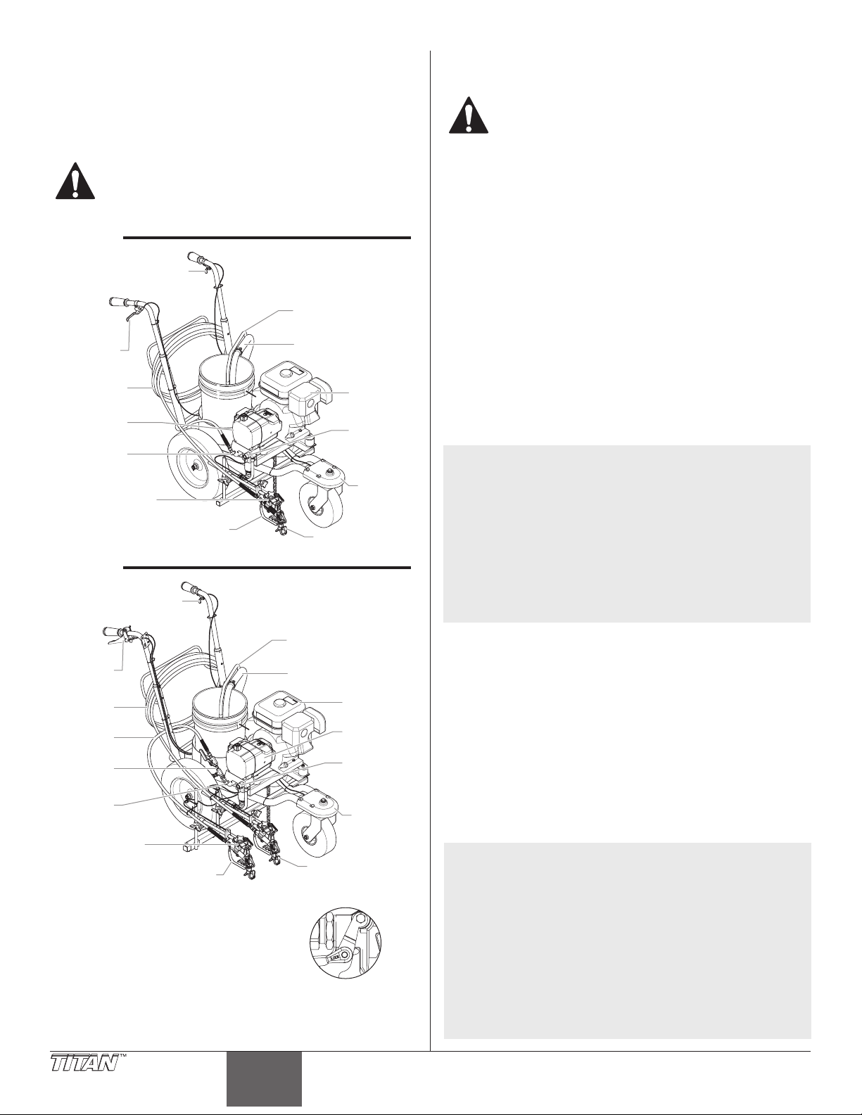
P
Embout
Ensemble
du pistolet
Pistolet de pulvérisateur (2)
ulvérisateur
Description générale
Cet appareil à peindre les lignes sans air est un outil mécanique de
précision utilisé pour pulvériser toutes sortes de matériaux pour
diérentes applications telles que les parcs de stationnement, les
bordures de trottoir et les terrains de sport. Lire et suivre ce manuel
d’instructions attentivement an de connaître la notice d’utilisation,
la maintenance et les consignes de sécurité de l’appareil.
Cet appareil produit un jet à très haute pression; avant
de le faire fonctionner, il est donc essentiel de lire et
de comprendre les avertissements formulés dans la
section Consignes de sécurité à l’avant de ce manuel.
1-Pistolet
Déclencheur de
verrouillage
de roue pivotante
Tuyau de retour
Détente
du pistolet
Flexible
ulvérisateur
sans air
Raccord
de exible
Ensemble de
support à pistolet
Pistolet de pulvérisateur
2-Pistolet
Déclencheur de
verrouillage
de roue pivotante
Détente
Flexible
(15m)
Flexible
(2m)
Clapet
antiretour
Raccord
de exible
Ensemble
de support à
pistolet (2)
Verrou de détente
Engager le verrou de détente à la n de
chaque utilisation du pistolet.
Pour verrouiller le pistolet, tournez
le verrou de gâchette vers l’avant et
légèrement vers le bas jusqu’à la butée.
Tuyau de siphon
Moteur
Soupape
PRIME/
SPRAY
de roue
avant
pivotante
Tuyau de retour
Tuyau de siphon
Moteur
P
sans air
Soupape
PRIME/
SPRAY
Ensemble
de roue
avant
pivotante
Embout (2)
Détente
verrouillée.
Fonctionnement
Remplissage de carburant (moteur à carburant)
L’essence est extrêmement inflammable et explosive
dans certaines conditions.
• Éteignez TOUJOURS le moteur avant de remplir le réservoir.
• Remplissez le réservoir de carburant dans un endroit bien aéré.
• Ne fumez pas et évitez toutes ammes ou étincelles dans
la zone de remplissage de carburant ou dans une zone de
stockage du carburant.
• Veillez à ne pas faire déborder le réservoir de carburant. Après
remplissage, assurez-vous que le bouchon du réservoir est
solidement vissé.
• Faites attention à ne pas renverser de carburant lors du
remplissage du réservoir. Les vapeurs ou les éclaboussures
de carburant peuvent s’enammer. En cas d’éclaboussures,
assurez-vous que la zone est bien sèche avant de faire
démarrer le moteur.
• Évitez l’inhalation répétée ou prolongée de brume ou de
vapeur et tout contact avec la peau.
• Tenez à l’écart des enfants.
Spécications de carburant
• Utilisez du carburant automobile avec un indice d’octane à la
pompe de 86 ou plus, ou avec un indice d’octane recherche
de 91 ou plus. L’utilisation d’un carburant avec un indice
d’octane inférieur peut provoquer des « cliquetis » ou des «
détonations » fortes (martèlement métallique) qui peuvent à
leur tour endommager le moteur.
NOTA : En cas de « détonations » ou de « cliquetis » sur un
Vous pouvez à l’occasion observer de faibles
• Le carburant sans plomb produit moins de dépôts et accroît la
• N’utilisez jamais de carburant altéré, contaminé ou de
Essences qui contiennent de l’alcool
Si vous décidez d’utiliser une essence qui contient de l’alcool
(essence-alcool), assurez-vous que l’indice d’octane est au moins
aussi élevé que celui recommandé par le fabricant du moteur. Il
existe deux types « d’essence-alcool » : l’un contient de l’éthanol et
l’autre du méthanol. N’utilisez pas d’essence-alcool contenant plus
de 10 % d’éthanol. N’utilisez jamais d’essence au méthanol (alcool
méthylique ou alcool de bois) si elle ne contient pas également
des cosolvants et des inhibiteurs de corrosion pour le méthanol.
N’utilisez pas d’essence contenant plus de 5 % de méthanol, même
en présence de cosolvants et d’inhibiteurs de corrosion.
NOTA : L’endommagement du circuit d’alimentation ou des
Avant d’acheter de l’essence dans une station-service
moteur à vitesse faible et normalement chargé,
changez de marque de carburant. Si le cliquetis ou les
détonations persistent, consultez le concessionnaire
agréé du fabricant du moteur. Le non-respect de
cette consigne est considéré comme une utilisation
incorrecte et les dommages subis en cas d’utilisation
incorrecte ne sont pas couvertes par la garantie
limitée du fabricant du moteur.
détonations lorsque la pompe travaille avec des charges
très importantes. Cela est normal, il signie simplement
que votre moteur fonctionne de manière ecace.
durée de vie des pièces du circuit d’échappement.
mélange huile/essence. Évitez l’accumulation de poussière,
de saleté ou la pénétration d’eau dans le réservoir.
problèmes liés au rendement du moteur attribuables
à l’utilisation de carburants contenant de l’alcool ne
sont pas couverts par la garantie. Le fabricant du
moteur ne peut être tenu responsable de l’utilisation
de carburants au méthanol compte tenu que les essais
de convenance sont incomplets en ce moment.
autre que celle que vous utilisez habituellement,
renseignez-vous pour savoir si l’essence contient de
l’alcool. Si tel est le cas, vériez le type et le pourcentage
d’alcool utilisé. Si vous observez un fonctionnement
anormal lorsque vous utilisez de l’essence contenant de
l’alcool, ou dont vous pensez qu’elle contient de l’alcool,
remplacez-la par de l’essence sans alcool.
20 © Titan Tool Inc. Tous droits réservés.
Français
Page 21

Vérications préliminaires
Câble de pistolet
Guide de contrôle
poteau à pistolet
Sec
Procédures à suivre avant de démarrer le moteur à essence de
l’appareil à peindre des lignes.
NOTA : Le pulvérisateur PL2850 est vendu en deux
versions, une version à un pulvérisateur et
une version à deux pulvérisateurs. Tous les
renseignements fournis dans le présent manuel
s’appliquent aux deux modèles, sauf lorsqu’il est
indiqué autrement.
1. Vérier que le tuyau-siphon et le tuyau de retour sont bien
attachés.
2. Tourner le bouton de régulation de la pression à fond dans le
sens inverse des aiguilles d’une montre jusqu’au minimum.
3. S’assurer que l’interrupteur MARCHE/ARRÊT est réglé à la
position ARRÊT.
4. Remplir la coupelle à l’huile de la section de liquide : environ
une cuillère à soupe de lubriant à joint de piston (lubriant à
piston).
IMPORTANT : Ne jamais utiliser l’appareil plus de dix secondes
s’il n’y a pas de liquide. L’utilisation de l’appareil sans liquide
peut user prématurément les garnitures.
7. Vérier le niveau d’huile du moteur. Le niveau d’huile du
moteur à essence est déterminé par le fabricant. Se reporter
au manuel du fabricant du moteur (fourni).
8. Fermer le levier de fermeture du carburant et verser de
l’essence dans le réservoir. Utiliser seulement une essence de
haute qualité, sans plomb.
Montage de 1-pistolet
1. À l’aide d’une clé plate, attacher du exible de pulvérisation
(15m) sans air au raccord de exible sur le pulvérisateur.
Resserrer à fond.
2. Attacher un pistolet pulvérisateur sans air au exible de
pulvérisation. À l’aide de deux clés plates (une sur le pistolet et
l’autre sur le exible), resserrer à fond.
Montage de 2-pistolet
1. À l’aide d’une clé, visser le clapet antiretour (avec un tuyau de
15 m attaché) au raccord de sortie sur le pulvérisateur. Serrez
solidement.
2. À l’aide d’une clé, visser le tuyau de pulvérisation de 2 m sans
air au raccord de sortie du haut sur clapet antiretour. Serrez
solidement.
Positionnement des pulvérisateurs (les deux pistolets)
1. Desserrer le bouton de la barre du support et glisser la
barre du support à pistolet à la position horizontale désirée.
S’assurer que le pistolet est assez éloigné du chariot an que
la roue arrière ne passe pas sur la répartition de pulvérisation
fraîche.
2. Montage du second pistolet (s’il y a lieu) -
a. Glisser la seconde barre du support à pistolet sur le bout de la
b. Desserrer le second bouton de poteau à pistolet et glisser le poteau
c. Passer le second câble de pistolet à travers le bloc et les guides-
première barre du support à pistolet. Fixer la barre en place en
serrant le bouton de la seconde barre du support à pistolet.
à la position horizontale désirée.
câbles, sous le châssis et vers la poignée du chariot. Utiliser les
attaches à tête d’équerre pour xer le câble au châssis.
IMPORTANT : S’assurer que le câble ne touche pas les pneus ou
ne nuit pas à la mobilité du chariot.
d. Insérer l’ensemble de câbles du pistolet dans le trou du guide de
e. Attacher le bout à crochet du câble dans le trou de la plaque de
contrôle jusqu’à ce qu’il entre en place.
levier.
Plaque
de levier
NOTA: Voir la section « Régler la tension de la détente »
3. Desserrer la bride(s) du tuyau élévateur du pistolet et glisser
du pistolet
an de vérier si le câble est installé correctement.
le pistolet(s) de pulvérisation à la position(s) verticale désirée.
Une distance de 6 po de la buse à la surface à pulvériser est un
bon point de départ.
Bride du
tuyau
élévateur
Bouton de
la barre du
support
Flexible
de 2 m
Clapet
antiretour
Flexible
de 15 m
Raccord
de exible
3. Attacher un pistolet pulvérisateur sans air à chacun des
tuyaux de pulvérisation. À l’aide de deux clés plates (une sur le
pistolet et l’autre sur le tuyau), resserrer à fond.
NOTA : Si on prévoit utiliser les deux pistolets, s’assurer que
la manette de soupape est en position ouverte (la
manette est en ligne avec le tuyau de 2 m).
Soupape
est fermée
© Titan Tool Inc. Tous droits réservés. 21
Soupape
est ouverte
Bouton
onde barre
du support à
pistolet
Bloc
Second bouton de
Barre
du support
NOTA : La barre du support à pistolet et le pistolet
pulvérisateur peuvent être montés d’un côté ou de
l’autre du pulvérisateur. Consulter l’illustration «
position du pulvérisateur » près de la partie arrière
du présent manuel.
NOTA : La hauteur du pistolet pulvérisateur modie la
largeur du jet (c’est-à-dire, plus le pistolet est bas,
plus la ligne sera étroite). La grosseur de le buse
modie également la largeur de la ligne.
Français
Page 22

Sélectionneur de gâchette (pulvérisateurs à deux pistolets)
soupape du
de motor
1. Régler le sélectionneur de gâchette pour le bon
fonctionnement du pistolet de pulvérisation. Le levier du
pistolet sur la poignée de droite déclenche le pistolet ou les
liquide d’essai à travers le tuyau de retour dans le contenant
de vidange.
9. Arrêter le pulvérisateur en mettant l’interrupteur MARCHE/
ARRËT du pulvérisateur à la position ARRÊT.
pistolets. Le sélectionneur sur la gâchette doit être réglé pour
le premier pistolet, les deux pistolets ou le second pistolet.
IMPORTANT : Toujours tourner la détente du pistolet de
pulvérisation à la position verrouillée avant de modier le
sélectionneur de gâchette. De plus, libérer le câble de la gâchette
de son bloc en levant le câble du bloc. Il y aura un déclenchement
bref du pistolet au moment de libérer le câble de gâchette.
a. Premier pistolet — La position
b. Les deux pistolets — La position
c. Second pistolet — La position
du premier pistolet est lorsque
le sélectionneur se trouve dans
la position de gauche. Pousser le
levier vers l’intérieur du châssis
jusqu’à ce que la goupille engage
la plaque de gauche.
à deux pistolets est lorsque le
sélectionneur se trouve dans la
position du centre. Pousser le
levier vers la position du centre
jusqu’à ce que la goupille engage
les deux plaques. La goupille doit
engager les deux plaques.
du second pistolet est lorsque
le sélectionneur se trouve dans
la position de droite. Éloigner le
levier vers l’intérieur du châssis
jusqu’à ce que la goupille engage
la plaque de droite.
Préparation d’un nouveau vaporisateur
Si cet appareil est neuf, il contient encore un liquide d’essai mis en
usine pour le protéger de la corrosion en cours d’expédition ou
d’entreposage. Ce liquide doit être complètement éliminé au moyen
d’essence minérale avant que l’appareil puisse être utilisé.
IMPORTANT : La détente du pistolet doit
toujours être verrouillée lorsqu’on procède à
ces vérifications préliminaires.
1. Placer le tube-siphon dans un contenant
d’essence minérale ayant un point
d’inammabilité de 60 ºC (140 ºF) ou plus.
2. Placer le tuyau de retour dans un contenant
de vidange en métal.
3. Tourner le bouton de régulation de la
pression à fond dans le sens inverse des
aiguilles d’une montre jusqu’au minimum.
4. Mettre la soupape PRIME/SPRAY à la
position PRIME.
5. Mettre l’interrupteur MARCHE/ARRÊT du
moteur à la position MARCHE.
6. Pour procéder au démarrage
du moteur :
a. Ouvrir le levier de soupape du
carburant.
b. Placez le levier de papillon au
milieu.
c. Fermer le levier du volet d’air
du moteur.
d. Tout en tenant le châssis avec
une main, tirer rapidement
et avec force la corde de
démarrage. Ne pas lâcher la
corde quand elle se replie.
Répéter la manœuvre jusqu’à ce que le moteur démarre.
7. Mettre le pulvérisateur
en marche en mettant
l’interrupteur MARCHE/ARRËT
Levier
d’étrangleur
Levier de
carburant
Interrupteur
de pulvériser
à la position MARCHE.
8. Laisser le pulvérisateur en
Détente
verrouillée.
Levier
de papillion
Interrupteur
Corde de
démarrage
Bouton de
régulation
de pression
PRIME
Préparation avant de peindre
Avant de peindre, il est important de s’assurer que le liquide dans
l’appareil est compatible avec le produit à utiliser.
NOTA : L’incompatibilité liquide/produit peut provoquer le
IMPORTANT : La détente du pistolet doit toujours être verrouillée
lorsqu’on procède à ces vérifications préliminaires.
1. Placer le tube-siphon dans un contenant rempli du
2. Placer le tuyau de retour dans un contenant de vidange en
3. Tourner le bouton de régulation de la pression à fond dans le
4. Mettre la soupape PRIME/SPRAY à la position PRIME.
NOTA : Tenez le tube de retour dans le conteneur de
5. Mettre l’interrupteur MARCHE/ARRÊT du moteur à la position
6. Pour procéder au
a. Ouvrir le levier de soupape
b. Placez le levier de papillon
c. Fermer le levier du volet
d. Tout en tenant le châssis
7. Mettre l’interrupteur hors
8. Laisser le pulvérisateur en
9. Arrêter le pulvérisateur en
NOTA : S’assurer que l’embout ou le protège-embout ne
10. Placer la soupape PRIME/SPRAY à la position SPRAY.
11. Mettre le pulvérisateur en marche.
12. Tourner lentement le bouton de régulation de la pression
13. Déverrouiller le pistolet en plaçant le verrou de la détente
blocage des soupapes, ce qui entraînerait le besoin
de démonter et de nettoyer la section des liquides
du vaporisateur.
solvant approprié au matériel à pulvériser (se reporter aux
recommandations du fabricant du matériel). Par exemple,
l’eau est un solvant approprié pour la peinture au latex.
métal.
sens inverse des aiguilles d’une montre jusqu’au minimum.
déchets en faisant passer le PRIME / SPRAY soupape
de PRIME dans le cas où le pulvérisateur est sous
pression.
MARCHE.
Levier
démarrage du moteur :
du carburant.
au milieu.
d’air du moteur.
avec une main, tirer
rapidement et avec force
la corde de démarrage.
Ne pas lâcher la corde
quand elle se replie. Répéter la manœuvre jusqu’à ce que le moteur
démarre.
tension (position ARRÊT).
d’étrangleur
Levier de
soupape du
carburant
Interrupteur
de pulvériser
Levier
de papillion
Interrupteur
de motor
Corde de
démarrage
Bouton de
régulation
de pression
marche pendant 15 à 30
secondes pour purger le
solvant usé à travers le tuyau
de retour dans le contenant
de vidange.
mettant l’interrupteur MARCHE/ARRÊT à la position ARRÊT.
soient pas installés.
dans le sens des aiguilles d’une montre pour augmenter la
pression.
dans la position de déverrouillage.
marche pendant 15 à 30
secondes pour purger le
22 © Titan Tool Inc. Tous droits réservés.
Français
Page 23
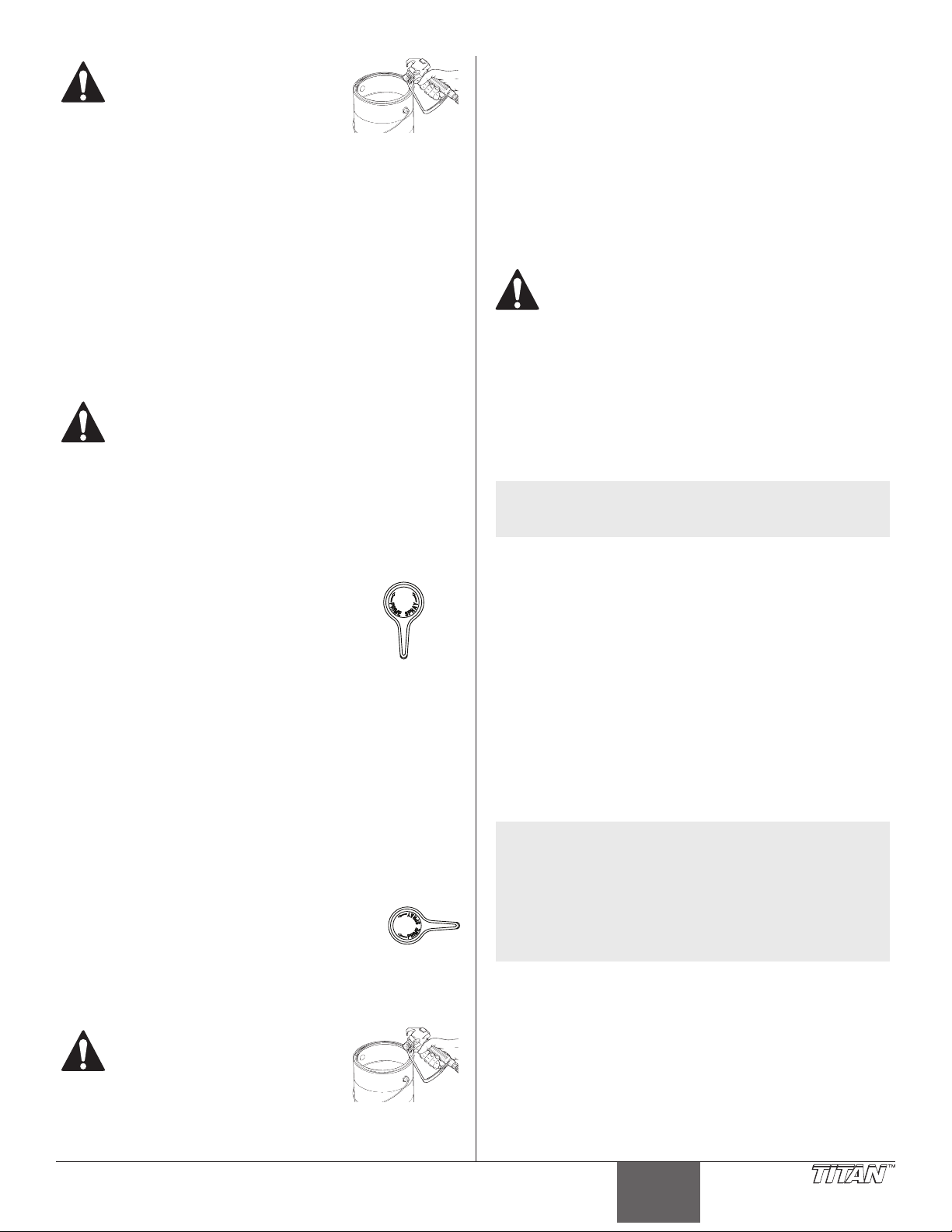
On doit mettre le pistolet à la terre
en le tenant contre le bord du
contenant de purge métallique
pendant qu’il se vide afin
d’éviter les risques de décharges
électrostatiques, lesquelles peuvent
provoquer un incendie.
14. Pointer le pistolet vers le contenant de vidange en métal et
serrer la détente pour purger complètement le solvant usé et
permettre le passage du solvant frais dans le pistolet.
15. Verrouiller le pistolet en tournant le verrou de la détente dans
la position de verrouillage.
16. Déposer le pistolet et augmenter la pression en tournant
lentement le bouton de régulation de la pression dans le sens
des aiguilles d’une montre jusqu’au maximum.
17. Vérier l’absence de fuite sur l’ensemble de l’appareil. En cas
de fuite, arrêter le pulvérisateur et suivre la procédure de
décompression de ce manuel avant de visser tous les raccords
ou les tuyaux.
18. Suivre la procédure de décompression de ce manuel avant de
passer du solvant à la peinture.
On doit effectuer la procédure de décompression chaque
fois qu’on arrête l’appareil pour en faire la maintenance,
en changer les réglages de vaporisation, en remplacer/
nettoyer les embouts ou en effectuer la préparation en
vue d’un nettoyage.
15. Pointer le pistolet dans le contenant de vidange en métal et
serrer la détente pour purger tout l’air et le solvant du tuyau
de pulvérisation et que la peinture s’échappe librement du
pistolet.
16. Verrouiller le pistolet en tournant le verrou de la détente dans
la position de verrouillage.
17. Tourner à fond le bouton de régulation de la pression dans le
sens inverse des aiguilles d’une montre jusqu’au minimum de
pression.
18. Arrêter le pulvérisateur.
19. Visser le protège-embout et l’embout sur le pistolet en suivant
les instructions contenues dans les sections du manuel
portant sur le protège-embout et l’embout.
RISQUES D’INJECTION. Ne pas vaporiser sans avoir
installé le protège-embout. Ne jamais appuyer
sur la détente sans avoir mis l’embout en position
de vaporisation ou de désobstruction. Toujours
enclencher le verrou de détente avant de retirer, de
remplacer ou de nettoyer l’embout
.
20. Mettre le pulvérisateur en marche.
21. Augmenter la pression en tournant lentement le bouton
de régulation de la pression dans le sens des aiguilles d’une
montre. Vérier la forme du jet et la position de la ligne sur un
long morceau de feutre pour toiture ou sur du carton.
a. Régler le bouton de régulation de la pression pour obtenir la forme
de jet recherchée. Maintenir le bouton de régulation de la pression
au minimum pour une bonne pulvérisation.
Peinture
1. Placer le tube-siphon dans un contenant de peinture.
2. Placer le tuyau de retour dans un contenant de vidange en
métal.
3. Tourner à fond le bouton de régulation de la pression dans le
sens inverse des aiguilles d’une montre jusqu’au minimum.
4. Mettre la soupape PRIME/SPRAY à la position
PRIME.
5. Mettre l’interrupteur MARCHE/ARRÊT du
moteur à la position MARCHE.
6. Pour procéder au démarrage du moteur :
a. Ouvrir le levier de soupape du carburant.
b. Placez le levier de papillon au milieu.
c. Fermer le levier du volet d’air du moteur.
d. Tout en tenant le châssis avec une main, tirer rapidement et avec
force la corde de démarrage. Ne pas lâcher la corde quand elle se
replie. Répéter la manœuvre jusqu’à ce que le moteur démarre.
7. Mettre le pulvérisateur en marche en mettant l’interrupteur
MARCHE/ARRÊT à la position MARCHE.
8. Laisser le pulvérisateur en marche jusqu’à ce que la peinture
commence à sortir du tuyau de retour pour se déverser dans
le contenant de vidange en métal.
9. Arrêtre le pulvérisateur en mettant l’interrupteur MARCHE/
ARRÊT à la position ARRÊT.
10. Retirer le tuyau de retour du contenant de vidange et le placer
dans sa position de fonctionnement, au-dessus du contenant
de peinture.
11. Régler la soupape PRIME/SPRAY à SPRAY.
12. Mettre le pulvérisateur en marche.
13. Tourner lentement le bouton de régulation de la
pression dans le sens des aiguilles d’une montre
pour augmenter la pression.
14. Déverrouiller le pistolet en plaçant le verrou de la détente
dans la position de déverrouillage.
PRIME
SPRAY
NOTA : Si la pression est trop élevée, l’embout subira une
usure prématurée et produira des éclaboussures de
surpulvérisation.
b. Vérier la largeur et la position de la ligne. Pour régler la position
du pistolet pulvérisateur, se reporter à la procédure « Vérications
préliminaires » de cette section.
22. S’assurer que le pistolet pulvérisateur est complètement
fermé lorsque la détente du pistolet est relâchée. Pour régler
la tension de la détente, se reporter à la procédure « Régler la
tension de la détente ».
Fonctionnement de la roue avant pivotante
La roue avant pivotante du chariot permet de pulvériser une ligne
droite ou d’autres formes de ligne. Lorsqu’on est debout derrière le
pulvérisateur, le déclencheur de verrouillage sur la poignée gauche
du chariot contrôle le fonctionnement de la roue avant pivotante.
1. Pour des lignes droites, verrouiller la roue avant pivotante en
pressant, puis en relâchant le déclencheur de verrouillage de
la roue et avancer le pulvérisateur.
2. Pour un mouvement libre de la roue avant pivotante, presser
et tenir le déclencheur de verrouillage de la roue pivotante.
NOTA : Pour verrouiller la roue avant pivotante pour
d’autres formes de lignes que les lignes droites,
presser et tenir le déclencheur de verrouillage de
la roue pivotante et enfoncer le bouton de blocage
sur le côté du déclencheur. Une fois le bouton de
blocage enfoncé, le déclencheur de verrouillage de
la roue pivotante peut être relâché. Pour relâcher la
tige de blocage, presser de nouveau le déclencheur
de verrouillage de la roue pivotante.
On doit mettre le pistolet à la terre
en le tenant contre le bord du
contenant de purge métallique
pendant qu’il se vide afin
d’éviter les risques de décharges
électrostatiques, lesquelles peuvent
provoquer un incendie.
© Titan Tool Inc. Tous droits réservés. 23
Français
Page 24
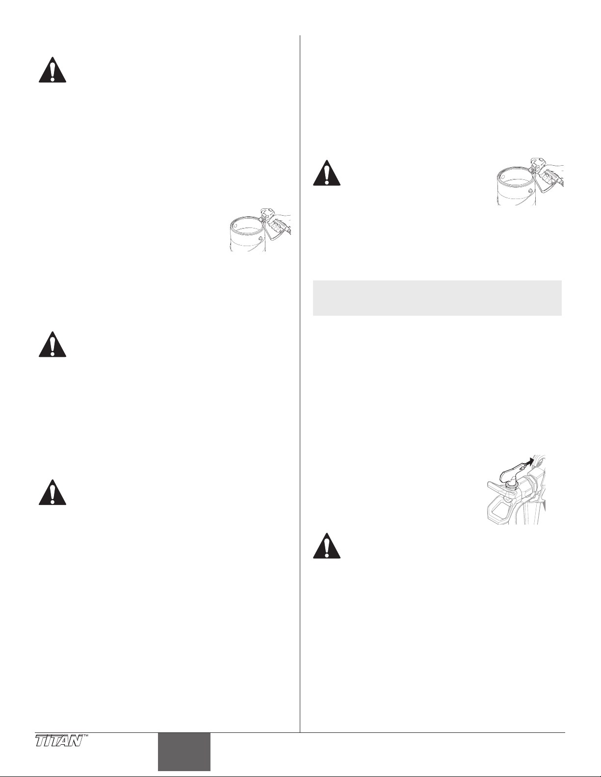
Procédure de décompression
On doit effectuer la procédure de décompression chaque
fois qu’on arrête l’appareil pour en faire la maintenance,
en changer les réglages de vaporisation, en remplacer/
nettoyer les embouts ou en effectuer la préparation en
vue d’un nettoyage.
1. Verrouiller le pistolet en mettant le verrou de détente à la
position appropriée.
2. Arrêter l’appareil en mettant le commutateur à la position
OFF.
3. Placer l’interrupteur MARCHE/ARRÊT à la position MARCHE et
démarrer le moteur.
4. Tourner à fond le bouton de régulation de la pression dans le
sens inverse des aiguilles d’une montre jusqu’au minimum.
5. Déverrouiller le pistolet en mettant le verrou de détente à la
position appropriée.
6. Tenir fermement la partie métallique du
pistolet contre le bord d’un contenant
métallique an d’éviter une accumulation
d’électricité statique.
7. Appuyer sur la détente du pistolet an de
purger tout l’air restant dans le exible.
8. Verrouiller le pistolet en mettant le verrou de détente à la
position appropriée.
9. Abaisser la soupape PRIME/SPRAY à la position PRIME.
Nettoyage
Directives particulières pour le nettoyage au moyen de
solvants inflammables :
• Purger le pistolet à l’extérieur de préférence, à une distance
d’au moins une longueur de exible de la pompe.
• Si le solvant usé est recueilli dans un contenant métallique
de 4 litres (1 gallon), celui-ci doit être inséré dans un second
contenant d’au moins 20 litres (5 gallons).
• L’endroit choisi doit être exempt de vapeurs inammables.
• On doit suivre les directives de nettoyage à la lettre.
IMPORTANT : Le vaporisateur, le flexible et le pistolet doivent
être nettoyés en profondeur après chaque journée d’utilisation
et ce, afin d’éviter les accumulations de produit susceptibles de
nuire grandement au rendement de l’appareil.
Lorsqu’on se sert d’essence minérale ou d’autres
solvants pour nettoyer le vaporisateur, le exible ou
le pistolet, on doit régler la pression au minimum et
retirer l’embout de la buse du pistolet. L’accumulation
d’électricité statique risque de provoquer des
incendies en présence de vapeurs inammables.
1. Suivre la Procédure de décompression à la section
Fonctionnement du présent manuel.
2. Retirer l’embout et le protège-embout, et les nettoyer au
moyen d’une brosse et du solvant approprié.
3. Placer le tube-siphon dans un contenant rempli du solvant
approprié (se reporter aux recommandations du fabricant du
matériel). Par exemple, l’eau est un solvant approprié pour la
peinture au latex.
4. Mettre le exible de retour dans un contenant de purge
métallique.
5. Abaisser la soupape PRIME/SPRAY à la position PRIME.
6. Placer l’interrupteur MARCHE/ARRÊT à la position MARCHE et
démarrer le moteur.
7. Mettre l’appareil en marche en mettant le commutateur à la
position ON.
8. Tourner lentement le bouton de régulation de la pression
dans le sens des aiguilles d’une montre pour augmenter la
pression jusqu’à ce que le liquide commence à s’échapper du
tuyau de retour.
9. Laisser le solvant circuler dans l’appareil pour évacuer
le produit de peinture par le exible de retour, jusqu’au
contenant de purge.
10. Tourner à fond le bouton de régulation de la pression dans le
sens inverse des aiguilles d’une montre jusqu’au minimum.
11. Arrêter l’appareil en mettant le commutateur à la position
OFF.
12. Soulever la soupape PRIME/SPRAY à la position SPRAY.
13. Mettre l’appareil en marche.
14. Tourner lentement le bouton de régulation de la pression
dans le sens des aiguilles d’une montre pour augmenter la
pression.
On doit mettre le pistolet à la terre
en le tenant contre le bord du
contenant de purge métallique
pendant qu’il se vide afin
d’éviter les risques de décharges
électrostatiques, lesquelles peuvent
provoquer un incendie.
15. Appuyer sur la détente en visant le contenant métallique pour
purger le produit du exible, jusqu’à ce que le solvant s’écoule
du pistolet.
16. Continuer d’appuyer sur la détente, en direction du contenant
métallique, jusqu’à ce que le solvant évacué soit propre.
NOTA : Pour l’entreposage à long terme en milieu froid,
remplir tous les composants de l’appareil d’essence
minérale.
17. Suivre la Procédure de décompression à la section
Fonctionnement du présent manuel.
18. Débrancher l’appareil et le ranger dans un endroit propre et
sec.
IMPORTANT : Ne pas ranger l’appareil sous pression.
Nettoyage de l’embout
1. Purger le pistolet avec le solvant immédiatement après avoir
terminé le travail.
2. Appliquer de l’huile sur les tiges coulissantes pour les
empêcher de se bloquer.
Si l’embout de pulvérisation est obstrué,
il faut le renverser avec le levier et
serrer la détente du pistolet. Une fois
l’obstruction expulsée de l’embout,
lâcher la détente, remettre l’embout en
place en le réglant sur la forme de jet et
reprendre la pulvérisation.
Ne pas tenter de débloquer ou de nettoyer l’embout
avec le doigt.
Ne pas utiliser une aiguille ou un objet pointu pour
nettoyer l’embout. Le carbure de tungstène pourrait
s’écailler.
24 © Titan Tool Inc. Tous droits réservés.
Français
Page 25

Maintenance
Avant de procéder, on doit suivre les directives de
la section Procédure de décompression du présent
manuel. On doit également respecter tous les autres
avertissements si on veut éviter les blessures par
injection, par contact avec une pièce mobile ou par
choc électrique.
NOTA : Tous les travaux concernant les moteurs Honda
doivent être eectués par un centre de service
autorisé de Honda.
Généralités concernant la maintenance
Pour réparer ou entretenir le vaporisateur, on pourrait avoir à recourir
aux outils suivants :
Tournevis étoile Clé hexagonale de 1,0 cm (3/8 po)
Pince à bec pointu Clé hexagonale de 0,8 cm (5/16 po)
Clé à ouverture variable Clé hexagonale de 0,6 cm (1/4 po)
Maillet en caoutchouc Clé hexagonale de 0,5 cm (3/16 po)
Tournevis plat Clé hexagonale de 0,3 cm (1/8 po)
Clé ouverte de1/2 po Clé ouverte de 7/8 po
1. Avant de procéder à la maintenance de n’importe quel
composant du vaporisateur, il faut lire attentivement
les directives ainsi que tous les avertissements qu’elles
contiennent.
IMPORTANT : Ne jamais tirer sur le cordon pour le débrancher,
ce qui pourrait détacher le connecteur des fils.
2. Vérier les résultats de la maintenance eectuée avant
d’utiliser le vaporisateur en conditions normales an de
s’assurer que le problème ait bel et bien été corrigé. Si le
vaporisateur ne fonctionne toujours pas comme il faut,
repasser la procédure pour s’assurer qu’elle ait été bien suivie.
Se reporter ensuite à la section Dépannage pour cerner la
source potentielle du problème.
3. S’assurer que l’endroit choisi soit bien ventilé si des solvants
sont utilisés pour le nettoyage. Toujours porter des lunettes
de protection lorsqu’on procède à la maintenance. D’autres
dispositifs protecteurs pourraient être requis selon le type
de solvant utilisé; on doit toujours communiquer avec le
fabricant de ce dernier pour obtenir ses recommandations à
cet eet.
4. Pour toute autre question relative à ce vaporisateur à
dépression, il sut de communiquer avec Titan :
Service à la clientèle (É.-U.) .............................. 1-800-526-5362
Télécopieur ................................................. 1-800-528-4826
Entretien du moteur
Pendant le transport d’un pulvérisateur à moteur à
essence, s’assurer que la soupape de carburant est bien
fermée.
NOTA : Pour des renseignements détaillés sur les
caractéristiques techniques et l’entretien, se
reporter au manuel fourni avec le pulvérisateur.
Faits importants concernant le pulvérisateur
Ce pulvérisateur à essence est doté d’un embrayage qui entre en
mouvement lorsque le pulvérisateur est en marche. Le système
de régulation de la pression du pulvérisateur met l’embrayage en
mouvement pour assurer la régulation de la pression. Pour éviter
l’usure inutile de l’embrayage, on conseille d’ajuster la vitesse du
moteur et la pression en vue de limiter la fréquence de mouvements
de l’embrayage. Pour réduire l’usure de l‘embrayage, se reporter aux
exemples ci-dessous.
Exemple :
Pour faire fonctionner un pistolet muni d’un embout de 0,019 po –
réduire la vitesse du moteur en ajustant le dispositif d’étranglement à
un niveau plus bas ou moyen et augmenter la pression jusqu’à ce que
les accumulations dans les bouts des formes de jets disparaissent.
Exemple :
Pour faire fonctionner un pistolet muni d’un embout de 0,025
po – augmenter la vitesse au maximum et augmenter la pression
jusqu’à ce que les accumulations dans les bouts des formes de jet
disparaissent.
Exemple :
Pour pulvériser des produits très uides à une basse pression – pour
réduire la surpression du pistolet et l’usure de l’embrayage, réduire
la vitesse du moteur au ralenti et diminuer la pression jusqu’à
l’obtention de la forme de jet recherchée.
Entretien périodique du moteur
Journalier
• Vérier et remplir le réservoir à essence.
• Après 20 heures (o un mois) de fonctionnement, vidanger
l’huile et mettre de l’huile fraîche. Vérier le niveau d’huile du
moteur et en ajouter au besoin.
Hebdomadaire
• Retirer le couvercle du ltre à air et nettoyer la pièce. Procéder
au remplacement de la pièce au besoin. Si le travail se déroule
dans un environnement inhabituellement poussiéreux, vérier
le ltre chaque jour et le remplacer au besoin. (Les pièces de
remplacement sont oerts chez le distributeur local de Titan.)
• Après 50 heures (o trois mois) d’utilisation : remplacer l’huile
de moteur.
Bougie d’allumage
• Utiliser uniquement des bougies de type (NKG) BPR6ES.
• Ajuster l’écartement des électrodes de la bougie de 0,028 po à
0,031 po (0,7-0,8 mm).
• Il faut utiliser une clé à bougie pour installer ou changer une
bougie.
© Titan Tool Inc. Tous droits réservés. 25
Français
Page 26

Régler la tension de la détente
pulvérisateur
Levier de détente
Bloc du câble
Bloc pompe
soupape
Joint de ltr
t
la poignée
Procédures à suivre pour régler le levier de tension à ressort de la
détente sur le support à pistolet. Le levier de détente tire et relâche la
détente du pistolet pulvérisateur lorsque la détente sur le chariot est
utilisée. Le réglage de la tension permet de s’assurer que le pistolet
se ferme lorsque la détente du pistolet est relâchée. Pour s’assurer
du bon réglage de la tension, vérier qu’il y a environ de 1/32 po à
1/16 po d’espace entre le levier de détente et la détente du pistolet
pulvérisateur.
IMPORTANT : La détente du pistolet doit toujours être verrouillée
lorsque l’on procède au réglage du système.
1. À l’aide d’une clé, dévisser le boulon sur le bloc du câble.
2. Déplacer le bloc du câble dans la direction appropriée an
de créer un espace de 1/32 po à 1/16 po entre le levier de
détente et la détente du pistolet pulvérisateur.
a. Glisser le bloc de câble vers le pistolet pour augmenter l’espace
entre le levier de détente et la détente du pistolet pulvérisateur.
b. Éloigner le bloc de câble du pistolet pour réduire l’espace entre le
levier de détente et la détente du pistolet pulvérisateur.
(boulonné à l’arrière)
Détente du
pistolet
Espace de 1/32 po
à 1/16 po
Nettoyage ou remplacement des ltres
Filtre de pompe
1. Dégager et retirer le logement du ltre.
2. Retirer le lter du ressort du support de ltre.
3. Inspecter le ltre; le nettoyer ou le remplacer au besoin.
4. Inspecter le joint; le nettoyer ou le remplacer au besoin.
5. Faites glisser le nouveau ltre ou nettoyer le ltre au cours du
support avec le soutien de l’adaptateur en place. oussez le
ltre dans le centre de la bloc pompe.
6. Glisser le logement sur le ltre et le visser solidement sur le
bloc pompe.
NOTA : Le ltre de logement devraient être serrés la main,
mais assurez-vous que le logement du ltre est
assise pleinement dans le bloc pompe.
Adaptateur
Ressort du
support de ltre
e
Ressort
du ltre
Filtre
Bloc pompe
Logemen
du ltre
3. Resserrer la vis pression.
Remplacement de la soupape PRIME/SPRAY
Pour eectuer cette procédure, on doit se procurer une trousse de
remplacement de soupape PRIME/SPRAY (P/N 800-915 ou 700-258).
1. Pousser la goupille hors de la manette de la soupape
2. Retirer la manette et la base à came.
3. Au moyen d’une clé, desserrer et retirer le logement de la
4. S’assurer que le joint d’étanchéité soit à sa place, et visser le
5. Mettre la base à came par dessus le logement de la soupape;
6. Aligner le trou dans la tige de soupape avec celui de la
7. Insérer la goupille à travers ces deux trous an de xer la
soupape.
nouveau logement dans le bloc pompe; serrer fermement à
l’aide d’une clé.
la lubrier au moyen de graisse et aligner la came avec le bloc
pompe.
manette.
manette en place.
Goupille
Logement
de la soupape
Goupille
Manette
de la
Tige de la soupape
Base à came
Joint d’étanchéité
Filtre de pistolet
1. Déverrouiller la détente du pistolet.
2. Dégager et retirer la poignée du corps du pistolet.
3. En tournant vers la droite, dévisser le ltre du corps.
NOTA : Le letage à gauche requiert qu’on tourne vers la
4. En tournant vers la gauche, visser le ltre nettoyé ou de
5. S’assurer que le joint de la poignée soit bien placé et visser
6. Verrouiller la détente du pistolet.
NOTA : Pour obtenir plus de détails, se renseigner sur les
droite pour dévisser.
rechange sur le corps.
solidement cette dernière sur le corps.
Corps du
pistolet
Filtre
Joint de
Poignée
numéros de pièce ou voir des dessins d’assemblage
à plus grande échelle, se reporter au manuel de
l’utilisateur du pistolet à dépression professionnel
LX-80 (no 313-2293).
26 © Titan Tool Inc. Tous droits réservés.
Français
Page 27
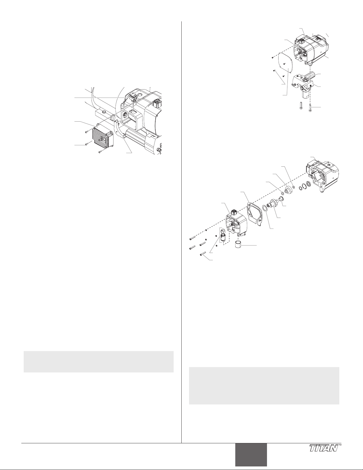
Remplacement de l’interrupteur MARCHE/ARRÊT
V
Relais
Logement de
couvercle
C
montage
pompe
Carter d’engrenage
Vis à tête creuse du corps de la pompe
(ON/OFF) du pulvérisateur
1. Suivre la procédure de décompression.
2. À l’aide d’un tournevis à pointe cruciforme, retirer les quatre
vis qui retiennent le dissipateur de chaleur et ses composants
dans le carter. Retirer soigneusement le dissipateur de chaleur
du carter. Déplacement doucement les composants en les
éloignant du pulvérisateur et laisser les composants pendre.
3. Repérer la partie inférieure de l’interrupteur MARCHE/ARRÊT
du pulvérisateur à l’intérieur du carter.
Interrupteur
MARCHE/ARRÊT
Dissipateur
de chaleur
is de xation du
dissipateur de
chaleur
5. À l’aide d’une clé
hexagonale de 3/8 po,
retirer les deux vis à tête
la pompe
Bielle
creuse qui permettent de
xer le tronçon au corps
de la pompe.
6. Abaisser le logement du
tronçon d’acheminement
d’environ 1/2 po du
carter d’engrenage pour
libérer le transducteur.
7. Faire glisser le
logement du tronçon
d’acheminement et la
tige de piston vers l’avant
jusqu’à ce que la tige
de piston sorte de la
Vis du
ouvercle
Piston
Bloc
pompe
Vis de
du bloc
rainure de xation sur le
coulisseau.
8. À l’aide d’une clé hexagonale de 1/4 po, retirer les quatre vis
à tête creuse qui permettent de xer le corps de la pompe au
carter d’engrenage.
4. Déconnecter les ls de l’interrupteur du pulvérisateur. Ne pas
oublier l’emplacement de chacun des deux ls (les marquer
avec des étiquettes, au besoin).
5. Abaisser les languettes de montage à chaque coin de
l’interrupteur du pulvérisateur à l’intérieur du carter, et retirer
l’interrupteur par la partie supérieure du carter.
6. Enclencher le nouvel interrupteur du pulvérisateur dans
l’orice prévu dans le carter.
7. Connecter les deux ls de l’interrupteur au nouvel interrupteur
du pulvérisateur. S’assurer que les ls sont reconnectés
aux points où ils se trouvaient avant d’être débranchés
(consulter les étiquettes utilisées à l’étape précédente de cette
procédure ou le schéma électrique dans la section « Liste de
pièces » de ce manuel).
8. Placer soigneusement le dissipateur de chaleur sur le carter en
prenant soin de ne pincer aucun ls.
9. Installer les quatre vis qui retiennent le dissipateur de chaleur
au carter. Visser fermement.
Remplacement des engrenages et/ou du coulisseau
1. À l’aide d’un tournevis à pointe cruciforme, dévisser les quatre
vis du couvercle avant. Retirer le couvercle.
2. Démarrer le moteur (consulter les procédures dans la section
« Fonctionnement » de ce manuel). Tourner le bouton de
régulation de la pression dans le sens des aiguilles d’une
montre au maximum.
3. Actionner rapidement l’interrupteur du pulvérisateur entre les
positions MARCHE et ARRÊT jusqu’à ce que le coulisseau et le
piston s’arrêtent au bas de leur course (aux positions les plus
basses).
4. Arrêter le moteur et eectuer la procédure de décompression.
NOTA : Pour remplacer le coulisseau, le tronçon
© Titan Tool Inc. Tous droits réservés. 27
d’acheminement doit être retiré du corps de la
pompe.
Rondelle de butée
Engrenage de sortie
Rondelle de butée
Joint statique
du carter
Corps de
la pompe
Rondelle de butée
cylindrique
Vilebrequin
Rondelle de butée
Manchon du coulisseau
Coulisseau
9. Glisser le corps de la pompe pour l’éloigner du carter
d’engrenage.
10. Retirer et nettoyer le joint statique. Le remplacer s’il est
endommagé.
11. Glisser le vilebrequin, avec les deux rondelles de butée hors
du corps de la pompe du côté du carter d’engrenage.
12. Retirer l’engrenage de sortie avec les deux rondelles de butée.
13. Nettoyer le vilebrequin en profondeur, l’engrenage de sortie
ainsi que toutes les rondelles de butée.
14. Inspecter toutes les pièces pour en vérier l’usure excessive
et remplacer celles qui sont endommagées ou usées. Si le
vilebrequin ou l’engrenage de sortie est remplacé, remplacer
également les rondelles de butée correspondantes.
15. Inspecter le pignon d’engrenage situé à l’extrémité de l’arbre
d’entrainement pour en vérier l’usure et le remplacer s’il est
endommagé ou usé (se reporter à la procédure « Entretien du
bloc d’embrayage » de cette section).
NOTA : Dans le cas où l’un des engrenages est usé et que
cela exige un remplacement, vérier si la graisse
dans le carter d’engrenage contient des particules
ou des limailles de métal. Enlever la graisse
contaminée et la remplacer avec la graisse fraîche
Lubriplate GR-132.
16. Glisser le coulisseau vers le haut et le sortir du manchon de
coulisseau situé en avant du corps de la pompe.
17. Inspecter les pièces pour en vérier l’usure.
a. Si le manchon de coulisseau est rayé ou excentré, le corps de la
pompe doit être remplacé.
Français
Page 28

b. Si le coulisseau est rayé ou le point de contact entre la bielle et
Logement de la pompe
is de montage
du bloc pompe
le coulisseau eectue des mouvements non rotatoires, il faut
remplacer le coulisseau. Si le coulisseau doit être également
remplacé si le coussinet de la bielle présente des signes d’usure.
c. Toutes les pièces qui seront utilisées plus d’une fois doivent être
nettoyées en profondeur, y compris la bielle. Nettoyer également la
goupille du vilebrequin autour de laquelle tourne le coussinet de la
bielle.
18. Appliquer une couche fraîche de graisse Lubriplate GR-132
sur l’engrenage de sortie et sur chaque côté de ses rondelles
de butée. Placer les rondelles de butée sur leur arbre de
l’engrenage de sortie.
19. Lubrier l’engrenage de sortie avec de la graisse Lubriplate
GR-132 fraîche. Insérer l’engrenage dans son orice prévu
dans le carter d’engrenage, la partie dentée en premier. Les
dents de l’engrenage vont s’accoupler avec celles du pignon
de l’arbre d’entraînement.
20. Appliquer une couche abondante de graisse Lubriplate GR132 fraîche sur toutes les surfaces de la rondelle de butée
cylindrique du vilebrequin.
21. Glisser l’extrémité plate de la rondelle de butée cylindrique
derrière l’engrenage sur l’engrenage de sortie, en alignant son
orice avec l’orice de la bielle du carter d’engrenage prévu
pour le vilebrequin.
22. Lubrier en appliquant de la graisse Lubriplate GR-13 fraîche.
Glisser l’arbre de côté de l’engrenage du vilebrequin à travers
la rondelle de butée cylindrique jusqu’à son orice situé dans
le carter d’engrenage.
23. Placer la goupille à l’extrémité du vilebrequin près de la base du
carter d’engrenage (à la position de point mort du bas).
24. Lubrier les deux surfaces de la grande rondelle de butée du
vilebrequin avec de la graisse Lubriplate GR-132 fraîche. Placer
la rondelle de butée sur le vilebrequin contre l’engrenage.
25. Placer le joint statique du carter sur le carter d’engrenage des
goupilles de positionnement.
26. Lubrier la surface extérieure du coulisseau et la surface interne
du manchon de coulisseau avec de l’huile. Remplir la cuvette
du coulisseau avec la graisse Lubriplate 1242 (la cuvette du
coulisseau est la partie de l’ensemble à coulisseau où la bielle et
le coulisseau se joignent et pivotent).
27. Insérer le coulisseau dans le manchon du coulisseau.
28. Placer soigneusement le corps de la pompe devant le carter
d’engrenage, en alignant chaque goupille de positionnement
du carter d’engrenage avec son orice correspondant situé
dans le corps de la pompe. Glisser le corps de la pompe dans
le carter d’engrenage jusqu’à ce qu’il n’y ait plus d’espace
entre le corps de la pompe, le carter d’engrenage et le joint
statique.
Remplacement du transducteur
1. Desserrer et retirer les quatre vis du couvercle avant et retirer
ce dernier.
2. Arrêter le vaporisateur en le bas de course an que le piston
soit à sa position la plus basse.
3. Suivre la Procédure de décompression.
Avant de procéder, on doit suivre les directives de
la section Procédure de décompression du présent
manuel. On doit également respecter tous les autres
avertissements si on veut éviter les blessures par
injection, par contact avec une pièce mobile ou par choc
électrique. Le vaporisateur doit toujours être débranché
avant d’être entretenu ou réparé.
4. Incliner la pompe vers l’arrière pour accéder plus facilement à
la section des liquides.
5. Au moyen d’une clé hexagonale de 1,0 cm, desserrer et retirer
les deux vis de montage du bloc pompe.
6. Tirer sur le bloc pompe an de le faire ressortir d’environ
1,5 cm (1/2 po) de son logement, de manière à dégager le
transducteur.
7. Glisser le bloc pompe et la tige du piston vers l’avant jusqu’à ce
que cette dernière sorte de la rainure en T de la bielle.
8. Retirez le transducteur de la bloc pompe avec une clé.
9. Installer le nouveau transducteur dans le logement de la
pompe. Serrez avec une clé.
12. Remonter la pompe en reprenant les étapes 1 à 8 à l’envers.
IMPORTANT : S’assurer que le transducteur est aligné
correctement par rapport à l’orifice du tronçon d’acheminement
du produit pendant le réassemblage. Un mauvais alignement
peut endommager le joint statique du transducteur.
Bielle
Transducteur
Vis du
couvercle
Couvercle
Bloc
pompe
NOTA : Pendant que le corps de la pompe glisse en place,
IMPORTANT : Ne pas serrer le corps de la pompe contre le carter
d’engrenage.
29. Repérer les quatre vis à tête creuse et visser les rondelles de
blocage qui xent le corps de la pompe au carter d’engrenage.
30. À l’aide d’une clé hexagonale de 1/4 po, ajuster et serrer les
vis à tête creuse en alternance en suivant un motif en croix.
Appliquer un couple de 200 à 230 po-lb.
31. Glisser la partie supérieure de la tige de piston dans
l’ouverture rectangulaire du coulisseau.
32. Placer le bloc de pompe en dessous du carter d’engrenage et
pousser jusqu’à ce qu’il repose sur le carter d’engrenage.
33. Insérer les deux vis à tête creuse qui xent le tronçon
d’acheminement de la peinture au corps de la pompe, tout en
ajustant et en appliquant un couple de 400 à 440 po-lb.
34. Placer le couvercle sur le corps de la pompe. Fixer le couvercle
avant avec de quatre vis du couvercle avant.
28 © Titan Tool Inc. Tous droits réservés.
la goupille du vilebrequin commencera à sortir du
palier au centre du corps de la pompe. Placer le
coulisseau pour faire en sorte qu’au moment où la
goupille du vilebrequin sort du palier principal, elle
entraîne le coussinet de la bielle.
Français
V
Entretien du bloc d’embrayage
NOTA : Lorsqu’on remplace l’armature de l’embrayage, son
rotor doit être également remplacé. Cela permet
une usure équilibrée et une durée de vie maximale
des pièces de l’embrayage.
Retirer et remplacer l’armature du bloc d’embrayage
1. Suivre la procédure de décompression.
2. Trouver le l qui sort derrière boîtier du bouton de régulation
de la pression et qui le relie le faisceau de câbles du moteur.
Déconnecter ce l de son connecteur sur le faisceau de câbles
du moteur.
3. À l’aide d’une douille à 12 points de 5/16 po, dévisser les
quatre vis et xer les rondelles qui retiennent le carter
d’embrayage au carter de l’engrenage.
4. À l’aide d’une douille de 9/16 po, dévisser la vis qui retient le
carter d’engrenage au chariot.
5. Glisser le corps de la pompe et celui de l’engrenage en
l’éloignant du moteur pour les séparer du carter d’embrayage.
Page 29

d’
d’engrenage
embrayage
d’
réglage du
moyeu
L’armature
d’embrayage
de blocage
de chaleur
Vis hexagonale du
carter d’embrayage
Rondelle de blocage
Armature de
l’embrayage
Carter
engrenage
Carter
d’
Arbre du moteur
Manchon conique de blocage
Corps de
la pompe
Ensemble de vis
Vis du carter
6. Repérer l’armature de l’embrayage à l’extrémité de l’arbre du
moteur. Remarquer les deux ensembles de vis et l’orice leté,
inoccupé du manchon conique fendu au centre du moyeu
d’embrayage.
7. À l’aide d’une clé hexagonale de 1/8 po, dévisser les deux
ensembles de vis du manchon conique fendu.
8. Visser l’une des vis dans l’orice leté, inoccupé au manchon
conique fendu. Au fur et à mesure que la vis se resserre, le
manchon se desserrera. Dès que le manchon se desserre
susamment, retirer l’armature de l’embrayage de l’arbre du
moteur.
9. À l’aide de l’outil de
réglage du moyeu (no
de pièce 0555926), créer
une « réduction » de 0,10
po entre la surface de
friction de l’armature et la
partie frontale du moyeu
Moyeu
embrayage
Surface
plane
Outil de
d’embrayage.
NOTA : Un nouveau moyeu
d’embrayage et de l’armature
0.10"
sera pré-assemblé, mais le «
réduction » mai ne pas être
correct. Le « réduction » doit
encore être créé en utilisant de
l’outil de réglage du moyeu.
10. Pour remplacer l’armature de l’embrayage, aligner les trois
orices au niveau du manchon conique fendu dans l’armature
de l’embrayage et insérer le manchon au centre de l’armature
de l’embrayage.
11. Aligner la clé sur le manchon conique fendu avec la rainure de
clavette de l’arbre du moteur et glisser l’armature sur l’arbre
avec les orices tournés vers l’extérieur.
12. Appliquer du Loctite bleu sur les deux ensembles de vis
et insérer les vis dans le manchon conique fendu. Serrer
l’ensemble des vis en faisant seulement deux tours complets
pour chaque vis.
13. En utilisant l’outil de
réglage de l’embrayage
(no de pièce 0555926),
Manchon
conique
placer l’armature de
l’embrayage sur l’arbre
du moteur. Maintenir
l’outil devant le carter
d’embrayage, de façon
à ce que le centre, la
partie encastrée de l’outil,
enjambe l’armature
de l’embrayage. Tirer
Moteur
Carter
Ensemble
de vis
Outil de
réglage
l’armature de l’embrayage
vers l’outil jusqu’à ce que la face de l’armature se retrouve
contre l’outil.
14. Tout en maintenant la prise sur l’armature de l’embrayage
contre l’outil, utiliser la clé hexagonale de 1/8 po et resserrer
les vis dans le manchon conique fendu. Régler le couple entre
65 et 75 po-lb.
© Titan Tool Inc. Tous droits réservés. 29
15. S’assurer que la surface de friction de l’armature d’embrayage
est propre et exempte d’huile ou de graisse.
Démontage du rotor de l’embrayage, du champ de
l’embrayage et de l’arbre d’entraînement
1. Suivre les étapes 1 à 7 « Démontage/remplacement de
l’armature de l’embrayage ».
2. Repérer le rotor de l’embrayage situé dans la partie arrière
à l’intérieur du carter d’engrenage. Prendre noter des
emplacements de trois vis à tête creuse et des deux orices
letés, inoccupés situés sur le rotor de l’embrayage.
3. À l’aide de la clé hexagonale de 3/16 po, retirer les trois vis à
tête creuse et les rondelles de blocage qui xent le rotor de
l’embrayage à l’arbre d’entraînement.
4. Introduire les vis à tête creuse dans les orices letés
inoccupés et serrer en alternant. Cela va pousser le rotor
de l’embrayage à l’écartant de l’arbre d’entraînement et le
pignon.
5. À l’aide d’un tournevis à pointe cruciforme, retirer les quatre
vis qui xent le dissipateur de chaleur au carter. Démonter
soigneusement le dissipateur de chaleur du carter.
6. Repérer les deux ls du champ d’embrayage qui s’étendent
du carter d’engrenage au logement de commande. Prendre
soin de remarquer les points de connexion terminaux des ls
sur le relais (mettre des étiquettes, au besoin), et débrancher
les ls. Éloigner doucement le dissipateur de chaleur du carter
et le déposer sur la surface de travail à côté du logement de
commande.
7. Repérer les quatre paires de vis qui xent le champ
d’embrayage au carter d’embrayage. Ces vis sont localisées
sur la partie externe du carter d’engrenage aux points
correspondants à 12, 3, 6 et 9 sur le cadran d’une montre,
en face de l’extrémité du champ d’embrayage du carter
d’engrenage. À l’aide d’une clé hexagonale de 1/8 po, dévisser
les vis. Prendre soin de remarquer l’emplacement des deux ls
du champ d’embrayage par rapport à la rondelle isolante et la
prise pour alimentation électrique externe.
8. Glisser soigneusement le champ d’embrayage pour le sortir
du carter d’engrenage, en maintenant le champ du carré au
carter d’engrenage pour qu’il ne se plie pas.
Vis à tête creuse du
rotor de l’embrayage
Arbre d’entraînement
Fils du champ
d’embrayage
Rondelle
de blocage
Rotor
Champ
d’embrayage
de l’embrayage
Dissipateur
de chaleur
Ensemble
de vis
Vis du dissipateur
NOTA : Avant de démonter l’arbre d’entraînement, il faut
d’abord démonter le corps de la pompe du carter
d’engrenage.
9. À l’aide d’un tournevis à pointe cruciforme, dévisser les vis du
couvercle avant. Démonter le couvercle avant.
10. À l’aide d’une clé hexagonale de 1/4 po, dévisser les quatre
vis à tête creuse qui xent le corps de la pompe au carter
d’engrenage.
11. Glisser le corps de la pompe en l’éloignant du carter
d’engrenage.
Français
Page 30

12. Démonter et nettoyer le joint statique du carter. Le remplacer
Vis du couvercle avant
s’il est endommagé.
13. Repérer le pignon de l’arbre d’entraînement qui sort de l’avant
du carter d’engrenage. Retirer le petit circlip qui se trouve sur
le moyeu de l’arbre d’entraînement devant le roulement à
billes sur lequel repose l’arbre d’entraînement.
14. À partir du côté opposé du carter d’engrenage (côté
embrayage), pousser l’arbre d’entraînement à l’extérieur du
carter d’engrenage.
15. Inspecter le joint d’étanchéité situé à l’intérieur de l’orice où
se trouvait l’arbre d’entraînement. Remplacer en cas d’usure
ou de dommages. Pour enlever le joint d’étanchéité, utiliser
un tournevis à lame plate et soulever soigneusement le joint
d’étanchéité de l’orice.
16. Nettoyer l’intérieur du carter d’engrenage.
Fiche
Joint statique
du carter
Palier
Circlip
Petit circlip
Vis à tête creuse
Couvercle avant
Joint
d’étanchéité
Assemblage du rotor d’embrayage, champ d’embrayage
et arbre d’entraînement
1. Si la graisse du joint d’étanchéité de l’arbre d’entraînement
a été enlevée, placer un nouveau joint d’étanchéité dans
l’orice pour remplacer le vieux joint d’étanchéité.
2. À partir du côté où se trouve l’embrayage dans le carter
d’engrenage, introduire l’arbre d’entraînement dans l’orice, à
travers la graisse du joint d’étanchéité ainsi que le roulement à
billes situé du côté de l’engrenage dans le carter d’engrenage.
3. À partir du côté de l’engrenage du carter d’engrenage,
insérer le circlip dans la gorge située sur le moyeu de l’arbre
d’entraînement devant le roulement à billes.
4. Mettre le du joint statique du carter sur les goupilles de
positionnements du carter d’engrenage.
5. Placer soigneusement le corps de la pompe devant le carter
d’engrenage, en alignant chaque goupille de positionnements
du carter d’engrenage avec son orice correspondant situé
dans le corps de la pompe. Glisser le corps de la pompe dans
le carter d’engrenage jusqu’à ce qu’il n’y ait plus d’espace
entre le corps de la pompe, le carter d’engrenage et le joint
statique.
IMPORTANT : Ne serrer le corps de la pompe contre le carter
d’engrenage.
6. Repérer les quatre vis à tête creuse et les rondelles de
blocage qui rattachent le corps de la pompe contre le carter
d’engrenage.
7. À l’aide d’une clé hexagonale de 1/4 po, visser et serrer les
vis à tête creuse en alternance, en suivant un motif en croix.
Appliquer un couple de 200 à 230 po-lb.
8. Aligner les quatre orices situés à l’extérieur du champ de
l’embrayage avec les quatre orices des vis à tête creuse
dans le carter d’engrenage. Les ls du champ d’embrayage
devraient être placés environ à la position 1 h ou 2 h du
cadran d’une montre.
9. Guider les deux ls du champ d’embrayage à travers l’orice
et le logement de commande.
30 © Titan Tool Inc. Tous droits réservés.
Français
10. Glisser soigneusement le champ d’embrayage dans son
orice, puis dans le carter d’engrenage jusqu’à ce qu’il
arrive au fond du carter. Ne pas pincer les ls du champ
d’embrayage pendant l’installation.
11. Visser l’une des vis pression pointue dans son orice. À l’aide
d’une clé hexagonale de 1/8 po, tourner lentement la vis
jusqu’à ce qu’elle touche le champ d’embrayage. Ne pas
resserrer la vis pression. Le bout de la vis pression devrait
s’accoupler avec l’orice de point de foret dans le champ.
Vérier si le champ d’embrayage peut faire une rotation. S’il
tourne dans son orice, la vis pression n’est pas bien installée
dans le point de foret.
12. Une fois que la vis pression est correctement en place,
installer les trois autres vis pression pointues. Ne pas resserrer
les vis pression.
13. Resserrer chaque vis pression pointue, en alternance en
suivant un motif en croix jusqu’à ce qu’elles soient bien
serrées. Dès que les quatre vis pression pointues sont bien
serrées, serrer en alternance en suivant un motif en croix et
appliquer un couple de 70 à 80 po-lb.
IMPORTANT : Il est très important de visser, de bien serrer
et d’appliquer un couple uniformément sur les vis pression
pointue en suivant un motif en croix. C’est pour faire en sorte
que le champ d’embrayage reste bien centré dans le carter de
l’engrenage.
15. Aligner les trois orices de vis et l’orice de la goupille de
positionnement du rotor de l’embrayage avec les orices de
vis et la goupille de positionnement sur le moyeu de l’arbre
d’entraînement. Placer le rotor de l’embrayage sur le moyeu.
16. À l’aide d’une clé hexagonale de 3/16 po, visser les trois vis
à tête creuse et les rondelles de blocage à travers le rotor
de l’embrayage et dans le moyeu de l’arbre d’entraînement.
Visser et serrer de façon égale les vis à tête creuse et appliquer
un couple de 75 à 85 po-lb.
17. S’assurer que la surface de friction du rotor de l’embrayage est
propre et exempte d’huile ou de graisse.
18. Repérer les deux ls du champ d’embrayage dans le logement
de commande. Tirer prudemment à fond sur les ls qui sont
dans le logement de la prise pour alimentation électrique
externe pour qu’il n’y ait pas de ralentissement dans le
logement. Brancher les ls sur les terminaux du relais (se
reporter aux étiquettes utilisées plus tôt dans la procédure
ou en suivant le schéma électrique présenté dans la section «
Liste de pièces » de ce manuel).
19. Placer soigneusement le dissipateur de chaleur sur le
logement de commande en prenant soin de ne pincer aucun
ls.
20. Installer les quatre vis qui retiennent le dissipateur de chaleur
au logement de commande. Resserrer les vis.
Accouplement du carter d’engrenage et du carter
d’embrayage
1. Placer le carter de l’engrenage sur le chariot devant le carter
de l’embrayage. Aligner les goupilles de positionnement dans
le carter de l’engrenage avec leurs orices correspondants
dans le carter de l’embrayage. Glisser le carter de l’engrenage
dans le carter de l’embrayage jusqu’à ce qu’il n’y ait plus
d’espace entre les carters.
2. Visser les quatre vis hexagonales et les rondelles de blocage à
travers le carter d’embrayage et dans le carter de l’engrenage.
3. À l’aide d’une douille à 12 points de 5/6 po, visser et renforcer
les vis hexagonales en alternance en suivant un motif en croix.
Appliquer un couple de 140 à 155 po-lb.
4. À l’aide d’une douille de 9/16 po, visser la vis hexagonale
qui xe le carter de l’engrenage au chariot à travers la
partie inférieure du chariot et dans le carter de l’engrenage.
Appliquer un couple de 100 à 120 po-lb.
5. Brancher le l du logement de la prise pour alimentation
électrique externe à son connecteur homologue situé sur le
faisceau de câbles du moteur.
Page 31

Vérication de l’écartement de l’embrayage
de retenue
Tige du
is de montage
du bloc pompe
1. Retirer le bouchon en plastique qui recouvre la partie
supérieure du carter de l’embrayage. Regarder à travers
le port pour repérer l’armature de l’embrayage et le rotor
d‘embrayage.
2. Vérication l’écartement entre l’armature de l’embrayage et le
rotor de l’embrayage à l’aide d’une lame calibrée de 0,016 po
et une autre de 0,035 po.
a. Insérer chaque lame calibrée à travers le port et dans l’écartement
b. Tirer à plusieurs reprises le cordon de tirage du moteur pour faire
c. Si la lame calibrée de 0,016 po ne correspond pas à la taille de
entre l’armature de l’embrayage et le rotor de l’embrayage. La lame
calibrée de 0,016 po doit correspondre à la taille de l’écartement.
La lame calibrée de 0,035 po ne devrait pas pouvoir remplir
l’écartement.
roter l’armature de l’embrayage, en vériant l’écartement avec
chaque lame calibrée après chaque tirage.
l’écartement ou si la lame calibrée de 0,035 po correspond à la
taille de l’écartement à n’importe quel point de contrôle, il faut
procéder à un réajustement de l’écartement. On peut le faire en
modiant la position du moyeu de l’embrayage et les composants
de l’armature de l’arbre du moteur. Se référer à la section qui décrit
la procédure de « Démontage du rotor de l’embrayage, du champ
de l’embrayage et de l’arbre d’entraînement » dans ce manuel.
Maintenance de la section des liquides
On doit suivre les procédures suivantes pour eectuer la
maintenance des soupapes et remplacer les tampons graisseurs de la
section des liquides.
1. Desserrer et retirer les quatre vis du couvercle avant et retirer
ce dernier.
2. Démarrer le moteur (se référer aux procédures décrites dans
la section « Fonctionnement » de ce manuel). Régler le bouton
de régulation de la pression dans le sens des aiguilles d’une
montre jusqu’au maximum.
3. Actionner rapidement l’interrupteur MARCHE/ARRÊT du
pulvérisateur entre les positions MARCHE et ARRÊT jusqu’à
ce que le coulisseau et le piston s’arrêtent au point mort (les
positions les plus basses).
4. Arrêter le moteur et eectuer la procédure de décompression.
Avant de procéder, on doit suivre les directives de
la section Procédure de décompression du présent
manuel. On doit également respecter tous les autres
avertissements si on veut éviter les blessures par
injection, par contact avec une pièce mobile ou par choc
électrique.
Maintenance des soupapes
La conception de la section des liquides
du vaporisateur fait en sorte qu’on peut
accéder aux soupapes de retenue et de
sortie, de même qu’à leur siège respectif,
sans avoir à démonter toute la section.
Il arrive que ces soupapes soient mal
assises à cause de débris accumulés; en
suivant les directives ci-dessous, on peut
les nettoyer et inverser ou remplacer
leur siège.
NOTA : Garder le pulvérisateur
en position verticale au
cours de cette procédure.
1. Au moyen d’une clé, desserrer et
retirer le logement de la soupape
de retenue du bloc pompe.
2. Enlever tous les débris dans
le logement et examiner les
composants; si le siège est endommagé, l’inverser ou le
remplacer.
NOTA : Si le siège de la soupape d’admission est inversé
ou remplacé, il faut remplacer le roulement de la
soupape d’admission.
© Titan Tool Inc. Tous droits réservés. 31
Bloc pompe
Manchon
Cage inférieur
Cage inférieur
Clapet de
la soupape
de retenue
Siège de
la soupape
de retenue
Joint torique
de PTFE
Logement de
la soupape
3. À l’aide d’une clé hexagonale de 1 cm (3/8 po), dévisser et
retirer le logement de la soupape de sortie de la tige du piston.
NOTA: La tige du piston doit
toujours être raccordée à la
pompe quand on eectue
l’entretien de la soupape de
sortie; ce faisant, on évitera
que la tige pivote lorsqu’on
démonte la soupape.
4. Enlever tous les débris dans
le logement et examiner les
composants; si le siège est
endommagé, l’inverser ou le
remplacer.
NOTA : Si le siège de la soupape
piston
Joint
supérieur
Siège
supérieur
Clapet de
la soupape
de sortie
Joint
inferieur
Siège de
la soupape
de sortie
Soupape de
retenue
de refoulement est mis à
l’envers ou remplacé, il faut
remplacer le roulement de la
soupape de refoulement.
5. Retirer, nettoyer et inspecter la cage et le clapet supérieurs; les
remplacer s’ils sont usés ou endommagés.
6. Remonter les soupapes en reprenant les étapes ci-dessus à
l’envers. Appliquer du Loctite bleu (no de pièce 426-051) au
letage mâle du logement de la soupape d’entrée et serrer au
couple de 450-500 in-lbs.
Remplacement des tampons graisseurs
1. Retirer les soupape de retenue en suivant les directives de la
section Maintenance des soupapes ci-dessus.
NOTA: La valve de sortie n’a pas besoin d’être démonté à
partir de la tige de piston pour cette procédure.
2. Au moyen d’une clé
hexagonale de 1,0 cm,
desserrer et retirer les deux
vis de montage du bloc
pompe.
3. Tirer sur le bloc pompe
an de le faire ressortir
d’environ 1,5 cm de son
Écrou de
retenue
Guide-piston
Tampon
supérieur
logement.
4. Glisser le bloc pompe
et la tige du piston vers
l’avant jusqu’à ce que cette
Bloc pompe
dernière sorte de la rainure
en T de la bielle.
5. Glisser la tige du piston
hors de la partie inférieure
V
du bloc pompe.
6. Desserrer et retirer l’écrou
de retenue et le guidepiston du bloc pompe.
Tampons
inférieurs
7. Retirer les tampons
supérieur et inférieurs du
Tige du piston
bloc pompe.
8. Nettoyer le bloc pompe.
9. Repérer les nouvelles garnitures d’étanchéité inférieure
et supérieure et garnir les espaces autour des garnitures
d’étanchéité avec de la graisse. Lubrier les joints toriques à
l’extérieur des garnitures avec de la graisse.
10. Inspecter la tige du piston pour y déceler toute trace d’usure
et la remplacer au besoin.
11. Insérer la garniture supérieure dans le haut du bloc de la
pompe avec la lèvre surélevée de la garniture tournée vers le
bas.
12. Insérer le guidage du piston dans l’écrou de retenue. Visser à
la main l’écrou de retenue dans le bloc de la pompe jusqu’à ce
qu’il soit bien xé.
13. Préformer la garniture inférieure à l’aide du calibreur
correspondant (fourni dans la trousse de regarnissage).
Français
Page 32

14. Insérer partiellement la garniture inférieure dans la partie
inférieure du bloc de la pompe de façon à ce que le côté qui a
le joint torique plus proche à la face de la garniture soit tourné
vers le haut.
La partie surélevée
supérieur doivent être
vers le bas.
Partie surélevée
La grand bord
biseauté doivent être
vers le haut.
Grand bord biseauté
15. Pousser la garniture inférieure en place en utilisant l’outil
d’insertion de garniture (voir la partie de la liste des
composants de la section « Tronçon d’acheminement » pour le
no de pièce de l’outil d’insertion de garniture inférieure).
16. Inspecter la tige du piston pour y déceler toute trace d’usure
et la remplacer au besoin.
NOTA : Au moment de régler l’orientation du tube
d’aspiration, utiliser deux clés plates : une sur la vis
à tête hexagonale xe du pivot et une sur la vis à
tête hexagonale mobile du pivot. Cela empêchera
le logement de la soupape d’entrée de se dévisser
accidentellement.
26. Visser le tuyau de retour dans le bloc de la pompe et resserrer.
27. Placer le couvercle avant sur le carter d’engrenage et le xer à
l’aide des quatre vis du couvercle avant.
28. Démarrer le pulvérisateur en suivant la procédure décrite
dans la section « Fonctionnement » de ce manuel et vérier les
fuites.
NOTA : La trousse de regarnissage no 0555960 est
disponible. Pour obtenir de meilleurs résultats,
utiliser toutes les pièces contenues dans cette
trousse.
NOTA : Appliquer de la graisse sur l’outil de guidage du
piston et sur la tige de piston avant de les insérer
dans le bloc de la pompe.
17. Placer l’outil d’insertion de piston (fourni dans la trousse de
regarnissage) au dessus de la tige de piston.
18. Insérer la tige de piston au fond du bloc de la pompe, à
travers la garniture inférieure, en passant par la garniture
supérieure et sortir par l’écrou de retenue. À l’aide d’un maillet
en caoutchouc, taper doucement sur la base la tige du piston
jusqu’à ce qu’elle s’installe dans le bloc de la pompe.
NOTA : Au moment de procéder au regarnissage du tronçon
d’acheminement, s’assurer que la lèvre surélevée
au fond de la garniture inférieure se trouve
complètement à l’extérieur de la garniture autour
de la tige du piston après l’insertion de la tige du
piston.
19. Retirer l’outil d’insertion de piston de la tige du piston.
20. À l’aide d’une clé plate, resserrer l’écrou de retenue dans le
bloc de la pompe. Appliquer un couple de 300 à 360 po-lb.
21. Glisser la partie supérieure de la tige du piston dans la rainure
de xation dans le coulisseau.
22. Placer le bloc de la pompe en dessous du carter d’engrenage
et le pousser vers le haut jusqu’à ce qu’il touche le carter
d’engrenage.
IMPORTANT : S’assurer que le transducteur est correctement
aligné avec l’orifice du bloc de la pompe pendant le
réassemblage. Un mauvais alignement peut endommager le joint
statique du transducteur.
23. Visser les vis de montage du bloc de la pompe pour xer le
carter d’engrenage. Appliquer un couple de 400 à 440po-lb.
24. Réassembler le clapet de pied dans le bloc de la pompe.
Appliquer du Loctite bleu (no de pièce 426-051) au letage
mâle du logement de la soupape d’entrée et serrer au couple
de 450-500 in-lbs.
NOTA : Pendant le réassemblage, s’assurer que le joint
torique entre le bloc de la pompe et le logement du
clapet de pied est lubrié avec de la graisse et qu’il
est en place.
25. Remonter le dispositif d’aspiration dans la section des liquides.
Si le pivot est retiré du logement de la soupape d’entrée,
ajouter du Loctite bleu (no de pièce 426-051) au letage mâle.
Remplacer le tuyau de retour dans le collier de serrage sur le
tube-siphon.
32 © Titan Tool Inc. Tous droits réservés.
Français
Page 33

Dépannage
Problem
A. L’appareil ne fonctionne pas.
B. L’appareil ne s’amorce pas.
C. La pression ne se fait pas dans
l’appareil ou la pression n’est
pas uniforme.
D. Fuite de liquide dans la partie
supérieure de la section des
liquides.
E. Trop grand aux au pistolet
vaporisateur.
F. Forme de vaporisation
incorrecte.
G. L’outil n’est pas pouvoir.
Cause
1. Le réglage de pression est trop bas.
2. Câblage défectueux ou débranché.
3. Le réservoir à essence est vide.
1. La soupape de PRIME/SPRAY est en position
SPRAY.
2. Fuite d’air dans le exible du siphon/
d’aspiration.
3. Le ltre de la pompe et/ou le ltre d’entrée
sont bouchés.
4. Le exible de siphon/d’aspiration est bouché.
1. L’embout d’aspiration est usé.
2. L’embout d’aspiration est trop grand.
3. Le bouton de commande de la pression n’est
pas correctement xé.
4. Le ltre de la pompe, le ltre du pistolet ou le
ltre d’entrée sont bouchés.
5. Du produit s’échappe du exible de retour
lorsque la soupape de PRIME/SPRAY est en
position SPRAY.
6. Fuite d’air dans le exible du siphon/le
exible d’aspiration.
7. Il y a une fuite de liquide externe.
8. Il y a une fuite interne dans la section des
liquides (les tampons graisseurs sont usés et/
ou sales, les clapets sont usés).
9. Sièges de soupape usés.
1. Les tampons graisseurs supérieurs sont usés.
2. La tige du piston est usée.
1. Mauvais type de exible de vaporisation sans
air.
2. L’embout d’aspiration est usé ou trop grand.
3. Pression excessive.
1. L’embout d’aspiration est trop grand pour le
produit utilisé.
2. Mauvais réglage de pression.
3. Sortie de liquide insusante.
4. Le produit vaporisé est trop visqueux.
1. Le réglage de la pression est trop faible.
Solution
1. Faire tourner le bouton de commande de la pression
pour alimenter l’appareil et accroître la pression.
4. Vérier ou le faire réparer dans un centre d’entretien
agrée par Titan.
3. Remplir le réservoir à essence.
1. Faire tourner la soupape PRIME/SPRAY dans le sens des
aiguilles d’une montre en position PRIME.
2. Vérier le branchement du exible du siphon/
d’aspiration et serrer ou recoller le raccord avec du
ruban en PTFE.
3. Démonter le ltre de la pompe et le nettoyer. Démonter
le ltre d’entrée et le nettoyer.
4. Démonter le exible du siphon/d’aspiration et le nettoyer.
1. Remplacer l’embout d’aspiration selon les consignes qui
accompagnent le pistolet de vaporisation.
2. Remplacer l’embout d’aspiration par un embout à moins
large selon les consignes qui accompagnent le pistolet
de vaporisation.
3. Tourner le bouton dans le sens des aiguilles d’une
montre pour augmenter la pression.
4. Démonter le ltre de la pompe et le nettoyer. Retirer
le ltre du pistolet et le nettoyer. Démonter le ltre
d’entrée et le nettoyer.
5. Nettoyer ou remplacer la soupape de PRIME/SPRAY.
6. Vérier le branchement du exible du siphon/
d’aspiration et serrer ou recoller le raccord avec du
ruban en PTFE.
7. Vérier qu’il n’y a pas de fuites externes dans tous les
raccords. Resserrer les raccords au besoin.
8. Nettoyer les soupapes et la section des liquides selon
la procédure “Maintenance de la Section des Liquides”
décrite au chapitre Maintenance de ce manuel.
9. Inverser ou remplacer les sièges de soupape selon la
procédure “Maintenance de la Section des Liquides”
décrite au chapitre Maintenance de ce manuel.
1. Regarnir selon la procédure “Maintenance de la Section
des Liquides” décrite au chapitre Maintenance de ce
manuel.
2. Remplacer la tige du piston selon la procédure
“Maintenance de la Section des Liquides” décrite au
chapitre Maintenance de ce manuel.
1. Remplacer le exible par un exible de vaporisation de
peinture sans air en tresse de textile de 1/4” et de 15m
de longueur.
2. Remplacer l’embout d’aspiration selon les consignes qui
accompagnent le pistolet de vaporisation.
3. Faire tourner le bouton de commande de la pression
dans le sens inverse des aiguilles d’une montre pour
réduire la pression d’évaporation.
1. Remplacer l’embout d’aspiration par un embout neuf
ou plus petit selon les consignes qui accompagnent le
pistolet de vaporisation.
2. Faire tourner le bouton de commande de la pression
pour régler la pression sur une forme de vaporisation
plus adapter.
3. Nettoyer toutes les crépines et tous les ltres.
4. Ajouter du solvant au produit selon les
recommandations du fabricant.
1. Faire tourner le bouton de commande de la pression
dans le sens des aiguilles d’une montre pour augmenter
la pression.
© Titan Tool Inc. Tous droits réservés. 33
Français
Page 34

Información de seguridad importante
Lea toda la información de seguridad antes de
operar el equipo. Guarde estas insturcciones.
Indica una situación peligrosa que, de no evitarse,
puede causar la muerte o lesiones graves.
Para reducir los riesgos de incendios, explosiones,
descargas eléctricas o lesiones a las personas, lea y
entienda todas las instrucciones incluidas en este
manual. Familiarícese con los controles y el uso
adecuado del equipo.
ADVERTENCIA: EXPLOSIÓN O INCENDIO
Los vapores inamables, como los vapores de las pinturas
y los solventes, pueden encenderse o explotar en el área
de trabajo.
PREVENCIÓN:
1. Use el equipo solo en áreas bien ventiladas. Mantenga un
buen suministro de aire fresco moviéndose a través del área
para mantener el aire al interior del área de pulverización
libre de acumulación de vapores inamables. Mantenga el
conjunto de la bomba en un área bien ventilada. No pulverice
el conjunto de la bomba.
2. No llene el tanque de combustible mientras el motor esté en
marcha o está caliente; apague el motor y deje que se enfríe.
El combustible es inamable y puede encenderse o explotar si
se derrama sobre una supercie caliente.
3. Elimine todas las fuentes de encendido como luces de piloto,
cigarrillos, lámparas eléctricas portátiles y cubiertas plásticas
(potenciales arcos estáticos).
4. Mantenga el área de trabajo libre de desechos, lo que incluye
solventes, trapos y gasolina.
5. No conecte o desconecte cables de alimentación ni prenda o
apague interruptores de luz o de energía cuando hay vapores
inamables presentes.
6. Conecte a tierra el equipo y los objetos conductores en el área
de trabajo. Asegúrese de que la cadena de conexión a tierra
está en su lugar y de que alcance la tierra.
7. Use solo mangueras conectadas a tierra.
8. Sostenga rmemente la pistola pulverizadora en el costado de
un cubo conectado a tierra cuando se aprieta el gatillo hacia
un cubo.
9. Si hay formación estática de chispas o si usted siente una
descarga, detenga inmediatamente la operación.
10. Conozca el contenido de la pintura y de los solventes que
se pulverizan. Lea todas las hojas de datos de seguridad
de materiales (MSDS) y las etiquetas de los recipientes
proporcionadas con las pinturas y solventes. Siga las
instrucciones de seguridad de los fabricantes de las pinturas y
los solventes.
11. No use una pintura o un solvente que contenga hidrocarburos
halogenados. Tales como: cloro, fungicida, blanqueador,
cloruro de metileno y tricloroetano. Estos no son compatibles
con el aluminio. Contacte con el proveedor del recubrimiento
para obtener información acerca de la compatibilidad del
material con el aluminio.
12. Mantenga un extintor de incendios en el área.
ADVERTENCIA: LESIÓN POR INYECCIÓN
El ujo de pintura a alta presión que produce este
equipo puede perforar la piel y los tejidos subyacentes,
ocasionando lesiones graves y posible amputación.
CONSULTE A UN MÉDICO INMEDIATAMENTE.
PREVENCIÓN:
1. No apunte con la pistola ni pulverice sobre ninguna persona
ni animal.
34 © Titan Tool Inc. Todos los derechos reservados.
Español
2. Mantenga las manos y el resto del cuerpo lejos de la descarga.
Por ejemplo, no trate de detener fugas con ninguna parte de
su cuerpo.
3. Utilice siempre el protector de la boquilla. No pulverice sin el
protector en su sitio.
4. Utilice solamente la boquilla especicada por el fabricante.
5. Tenga cuidado al limpiar y cambiar las boquillas. Si la boquilla
se atasca durante la pulverización,
ponga SIEMPRE el seguro del gatillo de la pistola, apague la
bomba y libere toda la presión antes de reparar, limpiar el
protector o la boquilla o cambiar la boquilla. La presión no
se libera apagando el motor. Para liberar la presión hay que
poner la manija de la válvula PRIME/SPRAY (cebar/pulverizar)
en PRIME. Consulte el Procedimiento para liberar presión que
se describe en el manual de la bomba.
6. No deje el aparato con corriente ni con presión cuando nadie
esté pendiente de ella. Cuando no utilice el aparato, apáguelo
y libere la presión siguiendo las instrucciones del fabricante.
7. La pulverización a alta presión puede inyectar toxinas en el
cuerpo y producir daños graves en el mismo. En caso de que
esto ocurra, visite a un médico inmediatamente.
8. Compruebe las mangueras y las piezas en busca de daños;
una fuga puede inyectar material en la piel. Inspeccione la
manguera antes de cada uso. Sustituya las mangueras o las
piezas dañadas.
9. Este sistema es capaz de producir 3300 PSI / 22.8 MPa. Utilice
solamente piezas de repuesto o accesorios especicados por
el fabricante y con una capacidad nominal de 3300 PSI como
mínimo. Entre ellos se incluyen boquillas pulverizadoras,
protectores para las boquillas, pistolas, alargadores, racores y
mangueras.
10. Ponga siempre el seguro del gatillo cuando no esté
pulverizando. Verique que el seguro del gatillo funciona
correctamente.
11. Antes de utilizar el aparato, verique que todas las conexiones
son seguras.
12. Aprenda a detener el aparato y a liberar la presión
rápidamente. Familiarícese a conciencia con los controles. La
presión no se libera apagando el motor. Para liberar la presión
hay que poner la manija de la válvula PRIME/SPRAY (cebar/
pulverizar) en PRIME. Consulte el Procedimiento para liberar
presión que se describe en el manual de la bomba.
13. Quite siempre la boquilla pulverizadora antes de enjuagar o
limpiar el sistema.
NOTA PARA EL MÉDICO: La inyección a través de la piel es una
lesión traumática. Es importante tratar la lesión tan pronto
sea posible. NO retrase el tratamiento para investigar la
toxicidad. La toxicidad es un factor a considerar con ciertos
revestimientos inyectados directamente en la corriente
sanguínea. Puede ser aconsejable consultar con un cirujano
plástico o un cirujano especialista en reconstrucción de las
manos.
ADVERTENCIA: GENERAL
Puede causar daños materiales o lesiones graves.
PREVENCIÓN:
1. Cuando pinte, lleve siempre guantes, protección para los
ojos, ropa y un respirador o máscara adecuados. Vapores
peligrosos: Las pinturas, disolventes, insecticidas y otros
materiales pueden ser perjudiciales si se inhalan o entran en
contacto con el cuerpo. Los vapores pueden producir nauseas
intensas, desmayos o envenenamiento.
2. Nunca utilice el aparato ni pulverice cerca de niños. Mantenga
el equipo alejado de los niños en todo momento.
Page 35

Información de seguridad importante
3. No se estire demasiado ni se apoye sobre un soporte
inestable. Mantenga los pies bien apoyados y el equilibrio en
todo momento.
4. No se distraiga y tenga cuidado con lo que hace.
5. No utilice el aparato si está fatigado o se encuentra bajo la
inuencia del alcohol o de las drogas.
6. No retuerza ni doble la manguera en exceso. En la manguera
airless pueden aparecer fugas a causa del desgaste, de
retorcimientos o de un mal uso. Una fuga puede inyectar
material en la piel.
7. No exponga la manguera a temperaturas o presiones que
superen las especicadas por el fabricante.
8. No utilice la manguera como elemento de fuerza para tirar del
equipo o levantarlo.
9. Utilice la presión más baja posible para enjuagar el equipo.
10. Cumpla todos los reglamentos locales, estatales y nacionales
pertinentes relativos a ventilación, prevención de incendios y
funcionamiento.
11. Las normas sobre seguridad del gobierno de los Estados
Unidos se han adoptado al amparo de la Ley de salud y
seguridad ocupacional (OSHA). Deben consultarse tres
normas, particularmente la sección 1910 de las Normas
generales y la sección 1926 de las Normas sobre construcción.
12. Cada vez que vaya a utilizar el equipo, compruebe antes todas
las mangueras en busca de cortes, fugas, abrasión o bultos en
la cubierta. Compruebe el movimiento de los acoplamientos
y si están dañados. Sustituya inmediatamente una manguera
si descubre alguna de estas anomalías. No repare nunca
una manguera de pintura. Sustitúyala por una manguera
conductora a alta presión.
13. No pulverice al aire libre si hace viento.
14. Desenchufe siempre el cable antes de trabajar en el equipo.
IMPORTANTE: No cargue el equipo por el asa del carrito durante
la carga y descarga.
Seguridad con los motores de gasolina
El escape del motor de esta unidad contiene químicos
que el Estado de California ha determinado causan
cáncer, defectos de nacimiento u otros daños al
sistema reproductor.
1. Los motores están diseñados para proporcionar un servicio
seguro y able, si se utilizan de acuerdo a las instrucciones.
Lea y entienda las instrucciones del Manual del Propietario
de Honda antes de utilizar el motor. De lo contrario, podría
causar lesiones personales o daño al equipo.
2. Para evitar peligros de incendio y para proporcionar una
ventilación adecuada, mantenga el motor por lo menos a 1
metro de los edicios y de otro equipo durante su uso. No
coloque objetos inamables cerca del motor.
3. Mantenga a los niños y las mascotas alejados de la zona de
trabajo, pues existe la posibilidad de quemaduras causadas
por los componentes calientes del motor o lesiones causadas
por cualquier equipo en el que se utilice el motor.
4. Sepa cómo apagar el motor rápidamente y comprenda el
funcionamiento de todos los controles. Nunca permita a
nadie operar el motor sin las instrucciones apropiadas.
5. La gasolina es extremadamente inamable y es explosiva bajo
ciertas condiciones.
6. Llene el tanque de combustible en un lugar bien ventilado y
con el motor apagado. No fume ni permita que haya llamas
ni chispas en la zona de llenado ni en donde se almacena el
combustible.
7. No llene en exceso el tanque de combustible. Después de
ponerle combustible, asegúrese de que la tapa del tanque
esté cerrada completamente.
8. Tenga cuidado de no derramar el combustible. Los gases del
combustible o el combustible derramado pueden encenderse.
Si se derrama combustible, asegúrese de que la zona esté seca
antes de encender el motor.
9. Nunca utilice el motor en un lugar encerrado o connado. El
escape contiene gas de monóxido de carbono venenoso; la
exposición a este gas puede causar pérdida del conocimiento
y puede conducir a la muerte.
10. El escape se calienta mucho durante su uso y permanece
caliente durante un rato después de apagar el motor.
Asegúrese de no tocar el escape cuando esté caliente. Para
evitar quemaduras graves o peligros de incendio, deje que el
motor se enfríe antes de transportarlo o guardarlo bajo techo.
11. Nunca envíe ni transporte la unidad con gasolina en el tanque.
Especicaciones
Capacidad (GPM) 0.85 (3.2 LPM)
Tamaño max. de soportes uno pistola gun = 0.030”
dos pistolas = 0.021”
Max presión de pulverización 3300 PSI (22.8 MPa)
Potencia Motor de gasolina de 3.5 HP
Peso 138 lbs. (62.6 kg)
Contenido
Precauciones de seguridad ........................................................... 34
Especicaciones ............................................................................. 35
Descripción general ...................................................................... 36
Seguro del gatillo .......................................................................................36
Funcionamiento ............................................................................ 36
Abastecimiento de combustible ...........................................................36
Conguración ..............................................................................................37
Preparación de un rociador nuevo .......................................................38
Preparación para pintar ............................................................................38
Pintura ............................................................................................................39
Operación de la roldana delantera ......................................................39
Procedimiento de liberación la presión .............................................40
Limpieza ......................................................................................... 40
Limpieza de la punta de pulverización ...............................................41
Mantenimiento .............................................................................. 41
Notas generales de reparación y servicio ..........................................41
Mantenimiento del motor .......................................................................41
Ajuste de la tensión del gatillo ..............................................................42
Reemplazo de la válvula de PRIME/SPRAY .......................................42
Limpieza o reemplazo de ltros ............................................................42
Reemplazo de interruptor ON/OFF ......................................................42
Reemplazo de los engranajes o del conjunto deslizante .............43
Reemplazo del transductor .....................................................................44
Mantenimiento del conjunto de embrague .....................................44
Servicio a la sección de líquidos ............................................................47
Solución de problemas ................................................................. 48
Liste de piezas ................................................................................ 48
Ensamblaje principal .................................................................................48
Ensamblaje de la caja de engranajes ...................................................50
Ensamblaje de la sección de líquidos .................................................54
Conjunto de carro ......................................................................................56
Conjunto de rueda delantera .................................................................58
Conjunto de soporte de la pistola ........................................................60
Conjunto de freno ......................................................................................60
Accesorios .....................................................................................................62
Garantía .......................................................................................... 64
© Titan Tool Inc. Todos los derechos reservados. 35
Español
Page 36
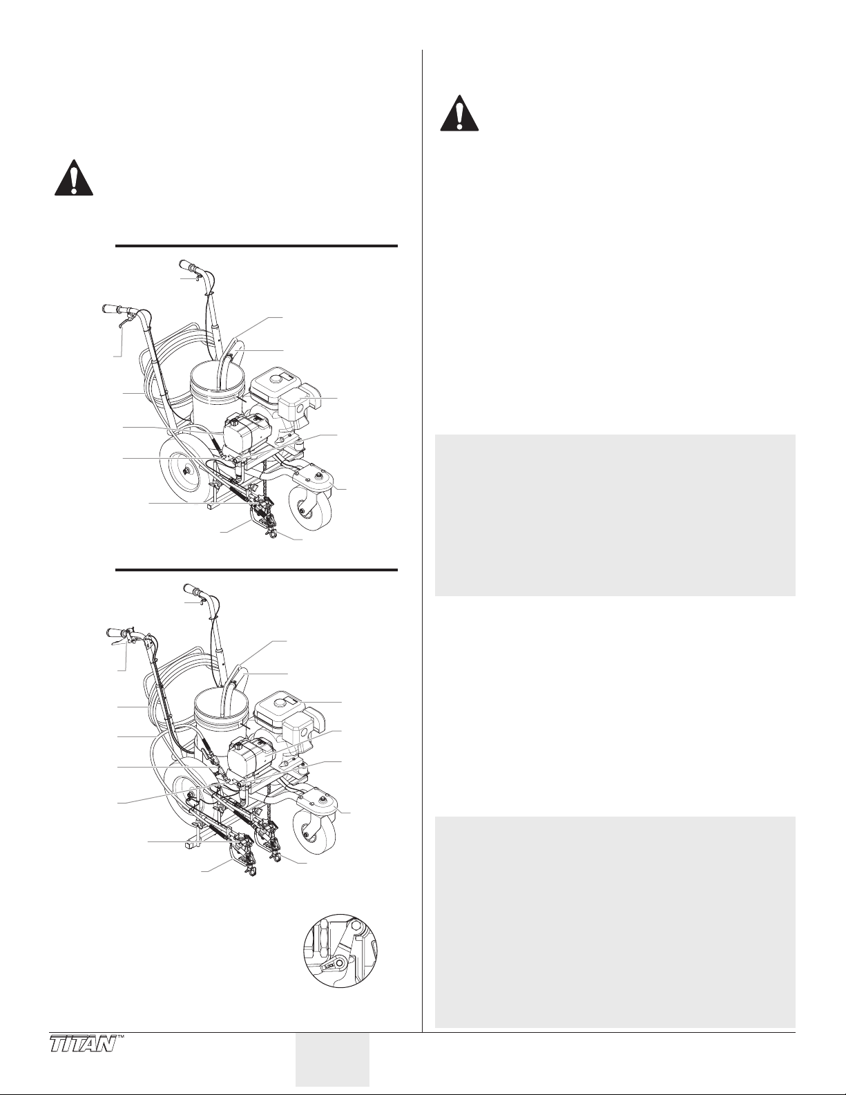
Descripción general
P
Conjunto de punta
de roldana
C
de punta (2)
de roldana
ulverizador
El trazalíneas sin aire es una herramienta mecánica de precisión que
se utiliza para pulverizar diversos tipos de materiales en varios tipos
de aplicaciones, entre las que se encuentran, estacionamientos,
aceras y pistas atléticas. Lea y siga este manual de instrucciones
detenidamente para conocer las instrucciones de operación, de
mantenimiento y la información de seguridad correspondiente.
Este equipo produce un flujo constante a presiones
extremadamente altas. Lea detalladamente las
advertencias de la sección Precauciones de seguridad
en la parte delantera de este manual antes de operar
este equipo.
1-Pistola
Funcionamiento
Abastecimiento de combustible (motor de gasolina)
La gasolina es extremadamente inflamable y es
explosiva en determinadas circunstancias.
• Apague SIEMPRE el motor antes de realizar el reabastecimiento.
• Realice el reabastecimiento en una zona bien ventilada.
• No fume ni permita que haya llamas ni chispas en el área de
reabastecimiento de combustible ni donde se almacene la
gasolina.
• No llene excesivamente el tanque de combustible. Tras
repostar, asegúrese de que la tapa del tanque está
adecuadamente cerrada y asegurada.
• Tenga cuidado de no derramar combustible cuando realiza el
reabastecimiento. El combustible derramado o el vapor del
Gatillo de la roldana
combustible pueden inamarse. Si se derrama combustible,
asegúrese de que el área está seca antes de arrancar el motor.
• Evite el contacto prolongado o repetido con la piel, o respirar
los vapores.
• Mantener fuera del alcance de los niños.
Especicaciones del combustible
• Utilice gasolina para automóviles que tenga un índice de
octano en la bomba de 86 o más, o que tenga un índice de
octano-investigación de 91 o más. El uso de una gasolina
de menos octanos puede causar un persistente “picado” o
“autoencendido” fuerte (un ruido metálico de golpes) que, si
es grave, puede llegar a dañar el motor.
NOTA: Si el “autoencendido” o “picado” se produce a una
velocidad constante del motor en condiciones de
carga normal, cambie de marca de gasolina. Si el
autoencendido o picado persiste, consulte a un
distribuidor autorizado del fabricante del motor.
No hacerlo se considera uso indebido, y los daños
causados por la mala utilización no están cubiertos por
la garantía limitada del fabricante del motor.
Gatillo de
la pistola
Manguera
de material
ulverizador
sin aire
Conexión
de salida
Conjunto de
soporte de la
pistola
Pistola pulverizadora
Tubo de retorno
Tubo de sifón
Motor
Válvula de
PRIME/
SPRAY
Conjunto
delantera
Ocasionalmente, es posible que experimente ligeros
2-Pistola
Gatillo de la roldana
• El combustible sin plomo produce menos depósitos en el
“autoencendidos” cuando opera en condiciones de
carga fuertes. No hay motivo para preocuparse, sólo
signica que su motor está funcionando ecazmente.
motor y en las bujías y prolonga la vida de los componentes
Tubo de retorno
del sistema de escape.
• Nunca utilice gasolina deteriorada o contaminada ni una
mezcla de aceite y gasolina. Evite introducir suciedad, polvo o
Gatillo de
la pistola
Manguera
(15m)
Manguera
(2m)
onjunto de
la válvula
Conexión
de salida
Conjunto de
soporte de la
pistola (2)
Pistola pulverizadora (2)
Tubo de sifón
Motor
P
sin aire
Válvula de
PRIME/
SPRAY
Conjunto
delantera
Conjunto
agua en el tanque de combustible.
Gasolinas que contienen alcohol
Si decide utilizar una gasolina que contiene alcohol (gasohol),
asegúrese de que su calicación en octanos es como mínimo tan
alta como la recomendada por el fabricante del motor. Existen dos
tipos de “gasohol”. uno contiene etanol, y el otro contiene metanol.
No utilice gasohol que contenga más del 10% de etanol. No utilice
gasolina que contenga metanol (alcohol metílico o de madera) que
no contenga también co-disolventes e inhibidores de la corrosión
para el metanol. Nunca utilice gasolina que contenga más del 5% de
metanol, incluso si tiene co-disolventes e inhibidores de la corrosión.
NOTA: Los daños en el sistema de combustible o los
problemas de rendimiento del motor producidos
como resultado del uso de combustibles que
contengan alcohol no están cubiertos por la garantía.
El fabricante del motor no puede respaldar el uso
de combustibles que contengan metanol, ya que las
Seguro del gatillo
Enganche el seguro del gatillo cuando la
pistola no esté en uso.
La pistola queda bloqueada cuando el
seguro del gatillo está en un ángulo de
90º (perpendicular) al gatillo en cualquier
dirección.
Seguro bloqueo
Antes de comprar gasolina en una gasolinera que no le
evidencias de su adecuación son incompletas en estos
momentos.
sea familiar, trate de averiguar si la gasolina contiene
alcohol. Si es así, conrme el tipo de alcohol utilizado
y su porcentaje. Si advierte alguna característica no
deseada en el funcionamiento mientras utiliza una
gasolina que contenga alcohol, o que usted piensa que
contiene alcohol, cambie a una gasolina que sepa que
no contiene alcohol.
36 © Titan Tool Inc. Todos los derechos reservados.
Español
Page 37
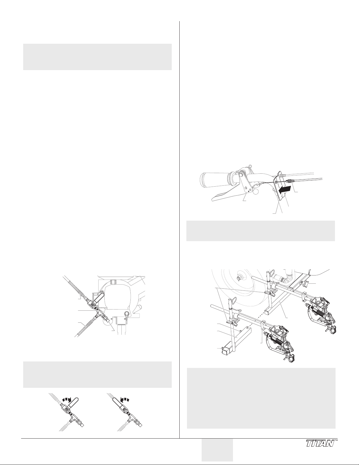
Conguración
C
de salida
lvula
ta
Guía de control
Barra de sopor
e
Realice el siguiente procedimiento antes de arrancar el motor de un
trazalíneas a gasolina.
NOTA: Existen dos versiones de PL2850, una versión de
una pistola y una versión de dos pistolas. Toda la
información de este manual es aplicable a ambas
unidades, excepto donde se señale lo contrario.
1. Asegúrese de que la tubo de sifón y la de retorno estén
conectadas y jas.
2. Gire completamente la perilla de control de presión en
sentido contrario al de las agujas del reloj hasta el ajuste de
presión más bajo.
3. Compruebe que el interruptor ON/OFF (Encendido/Apagado)
de la bomba esté en la posición OFF (Apagado).
4. Llene la copa de aceite de la sección de líquido con
aproximadamente una cucharada de lubricante para el sello
del pistón (Piston Lube).
IMPORTANTE: Nunca haga funcionar la unidad durante más
de diez segundos sin líquido. Si se hace funcionar esta unidad
sin líquido, se provocará un desgaste innecesario de las
empaquetaduras.
5. Revise el nivel de aceite del motor. El fabricante determina el
nivel de aceite del motor de gasolina. Consulte el manual de
servicio técnico del fabricante del motor (se proporciona).
6. Cierre la palanca de cierre de combustible y llene el tanque
con gasolina. Sólo utilice gasolina sin plomo de alta calidad.
Conguración de 1-pistola
1. Use una llave para conectar de la manguera de pulverización
(15 m) sin aire a la conexión de salida del pulverizador.
Apriete rmemente.
2. Conecte una pistola pulverizadora sin aire en la manguera de
pulverización. Use dos llaves (una en la pistola y la otra en la
manguera) para apretar rmemente.
Conguración de 2-pistola
1. Con una llave, enrosque el conjunto de la válvula (con una
manguera de 15 m conectada) en el acople de salida del
pulverizador. Apriete hasta que quede rme.
2. Con una llave, enrosque la manguera de pulverización sin
aire de 2 m en la conexión de salida superior el conjunto de la
válvula. Apriete hasta que quede rme.
Ubicación de las pistolas de pulverización (ambas
unidades)
1. Suelte la perilla de la barra de soporte y deslice la barra de
soporte de la pistola hasta la posición horizontal que desee.
Asegúrese de que la pistola esté lo sucientemente lejos del
carro para que la rueda trasera no pase sobre el patrón recién
pintado.
2. Montaje de la segunda pistola (si está equipada)
a. Deslice el conjunto de la barra de soporte de la segunda pistola
b. Suelte la perilla del poste de la segunda pistola y deslice el poste
c. Pase el cable de la segunda pistola por medio del bloque y de
sobre el extremo de la barra de soporte de la primera pistola.
Asegúrela en el lugar apretando la perilla de la barra de soporte de
la segunda pistola.
hacia la posición horizontal deseada.
las guías del cable, bajo el bastidor y por detrás hacia la pieza de
sujeción del carro. Utilice arrollamientos de uniones para asegurar
el cable al bastidor.
IMPORTANTE: Asegúrese de que el cable no esté tocando los
neumáticos ni esté interfiriendo con la movilidad del carro en
ningún sentido.
d. Inserte el conjunto del cable de la pistola en el agujero de la guía
e. Conecte el extremo encorvado del cable al agujero de la placa de la
de control hasta que encaje en el lugar.
palanca.
Placa de
palanca
Cable de
la pistola
NOTA: Consulte la sección “Ajuste de tensión del
3. Suelte la abrazadera(s) del montante ascendente de la pistola
gatillo” para vericar que el cable est instalado
correctamente.
y deslice la pistola(s) pulverizadora hasta la posición(s) vertical
que desee. Una distancia de 6” desde la punta a la supercie
de pulverización es un buen punto de partida.
3. Conecte una pistola de pulverización sin aire en cada una de
© Titan Tool Inc. Todos los derechos reservados. 37
Manguera
de 2 m
onjunto de
la válvula
Manguera
de 15 m
Conexión
las mangueras de pulverización. Con dos llaves (una en la
pistola y otra en la manguera), apriete hasta que quede rme.
NOTA: Si piensa utilizar ambas pistolas, asegúrese de que
la pieza de sujeción de la válvula est en la posición
abierta (la pieza de sujeción está alineada con la
manguera de 2 m).
Válvula
está
cerrada
Vá
está
abier
Perilla de
Abrazadera
del montante
ascendente
de la pistola
Perilla
de la 2da pistola
Perilla del poste
de la 2da pistola
Barra
de soporte
te
Bloque
la barra
de soport
NOTA: La barra de apoyo de la pistola y la pistola
pulverizadora se pueden montar en cualquier
lado del pulverizador. Consulte la ilustración
“Posiciones de la pistola de pulverización” cerca del
reverso de este manual.
NOTA: La altura de la pistola pulverizadora afecta el ancho
del patrón de pulverización (es decir, mientras más
abajo esté la pistola, más pequeño será el ancho de
la línea). El tamaño de la punta también afecta el
ancho de la línea.
Español
Page 38

Seguro bloqueo
terruptor
de ON/OFF
combustible
Palanca de
terruptor
de ON/OFF
de rociador
Selector del gatillo (unidades con dos pistolas)
1. Ajuste el selector del gatillo para que la pistola de
pulverización funcione correctamente. La palanca de la
pistola sobre el manubrio gatilla la pistola o las pistolas. El
selector sobre el gatillo debe estar ajustado para la primera
pistola, la segunda pistola o para ambas
IMPORTANTE: Siempre gire el bloqueo del gatillo de la pistola de
pulverización a la posición de bloqueo antes de realizar cualquier
ajuste al selector de gatillo. Además, desbloquee el cable del
gatillo levantando el cable hacia arriba y sacándolo del bloqueo.
Habrá un pequeño accionamiento de la pistola mientras se
desbloquea el cable del gatillo.
a. Primera pistola: La posición para
b. Ambas pistolas: La posición para
c. Segunda pistola: La posición para
la primera pistola es con el selector
en la posición izquierda. Accione la
palanca hacia el interior del bastidor,
hasta que el pasador se enganche en
la placa izquierda.
pistolas dobles es con el selector en la
posición central. Accione la palanca
hacia la posición del centro, hasta que
el pasador se enganche en ambas
placas. El pasador se debe enganchar
en ambas placas.
la segunda pistola es con el selector
en la posición derecha. Accione la
palanca hacia fuera del bastidor, hasta
que el pasador se enganche en la
placa derecha.
Preparación de un rociador nuevo
Si esta unidad es nueva, se envía con un líquido de prueba en
la sección de líquidos para evitar la corrosión durante el envío y
almacenamiento. Este líquido debe retirarse completamente del
sistema con alcoholes minerales antes de comenzar a rociar.
IMPORTANTE: Mantenga siempre el seguro
del gatillo de la pistola rociadora en la posición
bloqueada mientras prepara el sistema.
1. Coloque el tubo del sifón en un recipiente con
alcoholes minerales que tengan un punto de
inamación de 60º C (140º F) o superior.
2. Coloque la manguera de retorno en el
contenedor de desechos de metal.
3. Gire completamente la perilla de control de
presión en sentido contrario al de las agujas del
reloj hasta el ajuste de presión más bajo.
4. Mueva la válvula PRIME/SPRAY a la posición
PRIME.
5. Mueva el interruptor ON/OFF del motor a la
posición ON.
6. Arranque el motor:
a. Abra la palanca
b. Mueva la palanca de
c. Cierre la palanca de
d. Sostenga la estructura
de la válvula de
combustible.
aceleración hasta su
punto medio.
estrangulación del
motor.
con una mano, y tire
la soga de arranque
rápida y rmemente. Continúe sosteniendo la soga mientras ésta
se devuelve. Tire y regrese la soga hasta que arranque el motor.
Palanca de
estrangulación
Palanca de
la válvula de
Palanca de
aceleración
Soga de arranque
PRIME
In
del motor
7. Encienda el pulverizador
moviendo el interruptor
ON/OFF del pulverizador a
Interruptor
de rociadora
Perilla
de control
de presión
la posición ON.
8. Deje que el pulverizador
funcione durante 15 a 30
segundos para eliminar
el líquido de prueba por
la manguera de retorno y
hacia el contenedor de desechos.
9. Gire completamente la perilla de control de presión en
sentido contrario al de las agujas del reloj hasta el ajuste más
bajo.
10. Apague el pulverizador moviendo el interruptor ON/OFF del
pulverizador a la posición OFF.
Preparación para pintar
Antes de pintar, es importante revisar que el líquido del sistema sea
compatible con la pintura que va a utilizar.
NOTA: Los líquidos y pinturas incompatibles pueden
IMPORTANTE: Mantenga siempre el seguro del gatillo de la
pistola rociadora en la posición bloqueada mientras prepara el
sistema.
1. Coloque el tubo del sifón en un recipiente con el solvente
2. Coloque la manguera de retorno en el contenedor de
3. Gire completamente la perilla de control de presión en
4. Mueva la válvula PRIME/SPRAY a la posición PRIME.
NOTA: Sujete el tubo de retorno en el contenedor de
5. Mueva el interruptor ON/OFF del motor a la posición ON.
6. Arranque el motor:
a. Abra la palanca
b. Mueva la palanca de
c. Cierre la palanca de
d. Sostenga la estructura
7. Encienda el pulverizador
8. Deje que el pulverizador
9. Apague el pulverizador moviendo el interruptor ON/OFF del
causar que se atasquen cerradas las válvulas, lo cual
puede necesitar que se desmonte y limpie la sección
de líquidos del rociador.
adecuado para el material que se vaya a pulverizar (consulte
las recomendaciones del fabricante del material). Un ejemplo
del solvente adecuado es el agua para la pintura látex.
desechos de metal.
sentido contrario al de las agujas del reloj hasta el ajuste de
presión más bajo.
residuos al mover el PRIME / SPRAY válvula
de PRIME en caso de que el pulverizador es
presurizado.
estrangulación
de la válvula de
combustible.
aceleración hasta su
punto medio.
estrangulación del
motor.
con una mano, y tire
la soga de arranque
rápida y rmemente. Continúe sosteniendo la soga mientras ésta
se devuelve. Tire y regrese la soga hasta que arranque el motor.
Palanca de
la válvula de
Interruptor
moviendo el interruptor
ON/OFF del pulverizador a
Palanca de
aceleración
Soga de arranque
de control
a
de presión
In
del motor
Perilla
la posición ON.
funcione durante 15 a 30
segundos para eliminar
el solvente antiguo por
la manguera de retorno y
hacia el contenedor de desechos de metal.
pulverizador a la posición OFF.
38 © Titan Tool Inc. Todos los derechos reservados.
Español
Page 39

NOTA: Fíjese que la pistola rociadora no tenga instalada
PRIME
una punta o protección de punta.
10. Mueva la válvula PRIME/SPRAY a la posición SPRAY.
11. Encienda el pulverizador.
12. Gire lentamente la perilla de control de presión en el sentido
de las agujas del reloj para aumentar la presión.
13. Desbloquee la pistola girando el seguro de su gatillo a la
posición desbloqueada.
Conecte a tierra la pistola
apoyándola contra el borde del
recipiente de metal mientras elimina
el líquido. De lo contrario puede
provocar la descarga de electricidad
estática, lo cual a su vez puede
ocasionar un incendio.
14. Apriete el gatillo de la pistola hacia el contenedor de desechos
de metal hasta que ya no quede solvente antiguo y comience
a salir solvente nuevo.
15. Bloquee la pistola girando el seguro de su gatillo a la posición
bloqueada.
16. Baje la pistola y aumente la presión girando la perilla de
control de presión lentamente en el sentido de las agujas del
reloj hacia el ajuste más alto.
17. Revise que el sistema no tenga fugas. Si las hay, apague
el pulverizador y siga el “Procedimiento de liberación de
presión” de este manual antes de apretar cualquier conexión o
manguera.
18. Siga el “Procedimiento de liberación de presión” de este
manual antes de cambiar del solvente a la pintura.
No deje de seguir el procedimiento para aliviar la
presión cuando apague la unidad por cualquier motivo,
incluso el servicio o ajuste de alguna pieza del sistema
de rociado, cambio o limpieza de las puntas rociadoras
o la preparación para la limpieza.
Pintura
1. Coloque el tubo de sifón en un recipiente con pintura.
2. Coloque la manguera de retorno en el contenedor de
desechos de metal.
3. Gire completamente la perilla de control de presión en
sentido contrario al de las agujas del reloj hasta el ajuste de
presión más bajo.
4. Mueva la válvula PRIME/SPRAY a la posición
PRIME.
5. Mueva el interruptor ON/OFF del motor a la
posición ON.
6. Arranque el motor:
a. Abra la palanca de la válvula de combustible.
b. Mueva la palanca de aceleración hasta su punto medio.
c. Cierre la palanca de estrangulación del motor.
d. Sostenga la estructura con una mano, y tire la soga de arranque
7. Encienda el pulverizador moviendo el interruptor ON/OFF del
8. Deje que el pulverizador funcione hasta que salga pintura por
9. Apague el pulverizador moviendo el interruptor ON/OFF del
10. Retire la manguera de retorno del contenedor de desechos
11. Mueva la válvula PRIME/SPRAY a la posición
12. Encienda el pulverizador.
rápida y rmemente. Continúe sosteniendo la soga mientras ésta
se devuelve. Tire y regrese la soga hasta que arranque el motor.
pulverizador a la posición ON.
la manguera de retorno hacia el contenedor de desechos de
metal.
pulverizador a la posición OFF.
y colóquela en la posición de funcionamiento sobre el
recipiente con pintura.
SPRAY.
SPRAY
13. Gire lentamente la perilla de control de presión en el sentido
de las agujas del reloj para aumentar la presión.
14. Desbloquee la pistola girando el seguro de su gatillo a la
posición desbloqueada.
Conecte a tierra la pistola
apoyándola contra el borde del
recipiente de metal mientras elimina
el líquido. De lo contrario puede
provocar la descarga de electricidad
estática, lo cual a su vez puede
ocasionar un incendio.
15. Apriete el gatillo de la pistola hacia el contenedor de desechos
de metal hasta que salga todo el aire y el solvente de la
manguera de pulverización, y hasta que la pintura uya sin
problemas por la pistola.
16. Bloquee la pistola girando el seguro de su gatillo a la posición
bloqueada.
17. Gire completamente la perilla de control de presión en sentido
contrario al de las agujas del reloj hasta el ajuste más bajo.
18. Apague el pulverizador.
19. Conecte la protección de la punta y la punta en la pistola
como se indica en los manuales de protección de la punta o
punta.
POSIBLE PELIGRO DE INYECCIÓN. No rocíe sin la
protección de la punta en su lugar. Nunca apriete el
gatillo de la pistola a menos que la punta esté en la
posición de rociado o desatasco. Siempre coloque
el seguro del gatillo de la pistola antes de retirar,
reemplazar o limpiar la punta.
20. Encienda el pulverizador.
21. Aumente la presión con la perilla de control de presión
girándola lentamente en el sentido de las agujas del reloj.
Pruebe el patrón de pulverización y la posición de la línea en
una pieza grande de eltro impermeable o cartón.
a. Ajuste la perilla de control de presión hasta que se atomice
completamente la pulverización de la pistola. Intente mantener la
perilla de control de presión en el ajuste más bajo que mantenga
una buena atomización.
NOTA: Si se sube la presión más de lo necesario para
atomizar la pintura causará el desgaste prematuro
de la punta y rociará en exceso.
b. Revise que exista un ancho y posición de línea adecuados. Si se
necesita ajustar la posición de la pistola pulverizadora, consulte
el procedimiento “Conguración” descrito anteriormente en esta
sección.
22. Asegúrese de que la pistola pulverizadora se apague
completamente cuando se suelte el gatillo de la pistola.
Si se necesita ajustar la tensión del gatillo, consulte el
procedimiento “Ajuste de la tensión del gatillo”.
Operación de la roldana delantera
La roldana delantera del carro está diseñada para seguir al
pulverizador en una línea recta o en movimiento libre. Desde atrás
del pulverizador, el gatillo en la manilla izquierda del carro controla la
operación de la roldana delantera.
1. Para bloquear la roldana delantera en la posición de línea
recta, apriete y suelte el gatillo de la roldana, y mueva el
pulverizador hacia delante.
2. Para permitir un movimiento libre de la roldana delantera,
apriete y mantenga presionado el gatillo de la roldana.
NOTA: Para bloquear la roldana delantera en el modo de
movimiento libre, apriete y mantenga apretado
el gatillo de la roldana y luego apriete el botón de
bloqueo al lado del gatillo. Luego de presionar el
botón de bloqueo, se puede soltar el gatillo de la
roldana. Para soltar el pasador de inmovilización,
apriete el gatillo de la roldana.
© Titan Tool Inc. Todos los derechos reservados. 39
Español
Page 40
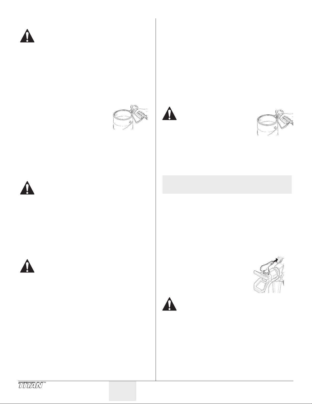
Procedimiento de liberación de presión
No deje de seguir el procedimiento de liberación
la presión cuando apague la unidad por cualquier
motivo, incluso el servicio o ajuste de alguna pieza del
sistema de rociado, cambio o limpieza de las puntas
rociadoras o la preparación para la limpieza.
1. Bloquee la pistola girando el seguro del gatillo de la pistola a
la posición bloqueada.
2. Apague la unidad moviendo el interruptor de ON/OFF a la
posición OFF.
3. Mueva el interruptor ON/OFF del motor a la posición OFF.
4. Gire completamente la perilla de control de presión en
sentido contrario al de las agujas del reloj hasta el ajuste más
bajo.
5. Desbloquee la pistola girando el seguro del gatillo de la
pistola a la posición liberada.
6. Sostenga rmemente la parte metálica
de la pistola contra el lado de un
recipiente metálico para conectar a
tierra la pistola y evitar la acumulación
de electricidad estática.
7. Accione el gatillo para aliviar toda presión que haya quedado
en la manguera.
8. Bloquee la pistola girando el seguro del gatillo de la pistola a
la posición bloqueada.
9. Mueva hacia abajo la válvula PRIME/SPRAY a la posición
PRIME.
Limpieza
Directives particulières pour le nettoyage au moyen de
solvants inflammables :
• Siempre lave la pistola rociadora preferiblemente afuera y alejada
por lo menos un largo de manguera de la bomba rociadora.
• Si recoge los solventes lavados en un recipiente metálico de
un galón, colóquelo en un recipiente vacío de cinco galones,
luego lave los solventes.
• El área debe estar libre de vapores inamables.
• Siga todas las instrucciones de limpieza.
IMPORTANTE: Deben limpiarse el rociador, la manguera y la
pistola totalmente después del uso diario. De lo contrario, se
permite la acumulación de material, afectando seriamente el
rendimiento de la unidad.
Siempre rocíe con la presión mínima y sin la boquilla
de la pistola al utilizar alcoholes minerales u otros
solventes para limpiar el rociador, la manguera o la
pistola. La acumulación de electricidad estática puede
producir un incendio o explosión en la presencia de
vapores inflamables.
1. Siga el “Procedimiento de alivio de presión” de la sección
Operación de este manual.
2. Retire la punta de la pistola y la protección y limpie con un
cepillo usando el solvente adecuado.
3. Coloque el tubo del sifón en un recipiente con el solvente
adecuado (consulte las recomendaciones del fabricante del
material). Un ejemplo del solvente adecuado es el agua para
la pintura látex.
4. Coloque la manguera de retorno en un recipiente metálico
para desecho.
5. Mueva hacia abajo la válvula PRIME/SPRAY a su posición
PRIME.
6. Mueva el interruptor ON/OFF del motor a la posición ON y
arránquelo.
7. Encienda la unidad moviendo el interruptor de ON/OFF a la
posición ON.
8. Gire lentamente la perilla de control de presión en el sentido
de las agujas del reloj para aumentar la presión hasta que
empiece a salir líquido de la manguera de retorno.
9. Deje circular el solvente a través de la unidad y purgue la
pintura de la manguera de retorno hacia el recipiente metálico
para desecho.
10. Gire completamente la perilla de control de presión en
sentido contrario al de las agujas del reloj hasta el ajuste de
presión más bajo.
11. Apague la unidad moviendo el interruptor de ON/OFF a la
posición OFF.
12. Mueva hacia arriba la válvula PRIME/SPRAY a su posición
SPRAY.
13. Encienda la unidad.
14. Gire lentamente la perilla de control de presión en el sentido
de las agujas del reloj para aumentar la presión.
Conecte a tierra la pistola
apoyándola contra el borde del
recipiente de metal mientras elimina
el líquido. De lo contrario puede
provocar la descarga de electricidad
estática, lo cual a su vez puede
ocasionar un incendio.
15. Dispare la pistola en el recipiente metálico para desecho hasta
que se haya purgado toda la pintura de la manguera y esté
saliendo solvente de la pistola.
16. Continúe apretando el gatillo de la pistola rociadora en el
recipiente de desecho hasta que el solvente que salga por la
pistola esté sin pintura.
NOTA: Para el almacenamiento a largo plazo o en
temperaturas frías, haga pasar alcoholes minerales
a través del sistema completo.
17. Siga el “¨Procedimiento de alivio de presión” de la sección
Operación de este manual.
18. Desenchufe la unidad y almacénela en un área limpia y seca.
IMPORTANTE: No almacene la unidad bajo presión.
Limpieza de la punta de pulverización
1. Limpie la pistola con solvente inmediatamente después de
terminar el trabajo.
2. Aceite los pasadores deslizantes para evitar que se agarroten.
En caso de que la punta de pulverización
se obstruya, inviértala con la palanca y
apriete el gatillo. Luego que la obstrucción
salga de la punta de pulverización, suelte
el gatillo, inviértala de vuelta al ajuste
de patrón de pulverización y continúe
pulverizando.
No intente limpiar la punta con sus dedos.
No utilice una aguja u otro artículo con punta afilada
para limpiar la punta de pulverización. El carburo de
tungsteno duro es quebradizo y se puede desportillar.
40 © Titan Tool Inc. Todos los derechos reservados.
Español
Page 41

Mantenimiento
Antes de proceder, siga el Procedimiento de alivio de
presión presentado anteriormente en este manual.
Además, siga todas las otras advertencias para reducir
el riesgo de una lesión por inyección, lesiones por
piezas en movimiento o choque eléctrico.
NOTA: Un centro de servicio técnico autorizado de Honda
debe realizar todos los trabajos en motores Honda.
Notas generales de reparación y servicio
Se necesitan las herramientas siguientes para reparar el rociador:
Destornillador Phillips Llave hexagonal de 3/8 de pulgada
Alicates de punta Llave hexagonal de 5/16 de pulgada
Llave ajustable Llave hexagonal de 1/4 de pulgada
Mazo de goma Llave hexagonal de 3/16 de pulgada
Destornillador de paleta Llave hexagonal de 1/8 de pulgada
Llave española de 1/2” Llave española de 7/8”
1. Antes de reparar alguna parte del rociador, lea
minuciosamente las instrucciones, incluidas todas las
advertencias.
IMPORTANTE: Nunca tire del cable para desconectarlo. Al
hacerlo podría soltarse el conector del cable.
2. Pruebe su reparación antes de usar rociador normalmente
para vericar que se haya resuelto el problema. Si el rociador
no funciona bien, revise el procedimiento de reparación para
determinar si todo se ha realizado en forma correcta. Consulte
los cuadros de Solución de problemas para ayudar a identicar
otros problemas posibles.
3. Compruebe que el área de servicio esté bien ventilada
en caso de que se estén utilizando solventes durante la
limpieza. Al hacer el mantenimiento siempre use gafas de
protección. Puede que se necesite equipo protector adicional
dependiendo del tipo de solvente de limpieza. Siempre pida
recomendaciones al proveedor de solventes.
4. Si tiene otras preguntas referentes al rociador Titan, llame a
Titan:
Servicio al cliente (EE.UU.) ................................ 1-800-526-5362
Fax ................................................................. 1-800-528-4826
Mantenimiento del motor
Cuando transporte un pulverizador con motor de
gasolina, asegúrese de que esté cortado el paso de
combustible.
NOTA: Para conocer las especicaciones y el
mantenimiento del motor, consulte el manual del
motor por separado que se proporciona con este
pulverizador.
Características importantes de este pulverizador
Este pulverizador impulsado por gasolina cuenta con un embrague
que se engancha cuando el pulverizador bombea. El sistema de
control de presión del pulverizador engancha y desengancha
el embrague para controlar la presión. Para evitar un desgaste
innecesario del embrague, se aconseja ajustar la velocidad y la
presión del motor para que se restrinja la cantidad de veces que
el embrague se engancha y desengancha. Con el n de reducir el
desgaste del embrague, consulte los siguientes ejemplos.
Ejemplo:
Trabajo con una pistola con una punta de 0.019”: Reduzca la
velocidad del motor ajustando la palanca de aceleración en un ajuste
bajo o medio y aumente la presión solamente hasta que se hayan
eliminado los extremos gruesos del patrón de pulverización.
Ejemplo:
Trabajo con una pistola con una punta de 0.025”: Aumente la
velocidad del motor a un ajuste mayor y aumente la presión
hasta que se hayan eliminado los extremos gruesos del patrón de
pulverización.
Ejemplo:
Pulverización de materiales de baja densidad a baja presión: Para
reducir la sobrecarga en la pistola y para disminuir el desgaste del
embrague, reduzca la velocidad del motor hasta dejarlo inactivo y
reduzca la presión hasta lograr el patrón de pulverización que desee.
Mantenimiento de rutina del motor
Diariamente
• Revise y llene el tanque de gasolina.
• Después de las primeras 20 (o un meses) horas de
funcionamiento, drene el aceite y vuelva a llenar con aceite
limpio. Revise el nivel de aceite del motor y llene según sea
necesario.
Semanalmente
• Retire la cubierta del ltro de aire y limpie el elemento.
Reemplace el elemento si fuese necesario. Si opera la unidad
en un entorno inusualmente sucio, revise el ltro diariamente
y reemplácelo si fuese necesario. (Puede adquirir los repuestos
por medio de su distribuidor local de Titan).
• Después de cada 50 horas (o tres meses) de funcionamiento:
cambie el aceite del motor.
Bujía de encendido
• Utilice solamente una bujía (NGK) BPR6ES.
• Separe los electrodos de la bujía de 0.028” a 0.031” (0.7-0.8
mm)
• Asegúrese de utilizar una llave para la bujía de encendido
cuando la instale o retire.
© Titan Tool Inc. Todos los derechos reservados. 41
Español
Page 42

Ajuste de la tensión del gatillo
Palanca de gatillo
Bloqueo del cable (perno
Bloque de
Mango de
de la bomba
Caja del
Mango
Utilice el siguiente procedimiento para ajustar la tensión del resorte
de la palanca de gatillo en el conjunto de soporte de la pistola. La
palanca de gatillo tira y suelta el gatillo de la pistola pulverizadora
cuando se opera con el gatillo del carro. La tensión correcta garantiza
que la pistola se apagará cuando se suelte el gatillo. Para garantizar
la tensión correcta, debe haber un espacio de aproximadamente
1/32” a 1/16” entre la palanca de gatillo y el gatillo de la pistola
pulverizadora.
IMPORTANTE: Mantenga siempre el seguro del gatillo de la
pistola pulverizadora en la posición bloqueada mientras ajusta el
sistema.
1. Use una llave para soltar el perno en el bloqueo del cable.
2. Mueva el bloqueo del cable en la dirección correcta para crear
un espacio de 1/32” a 1/16” entre la palanca de gatillo y el
gatillo de la pistola pulverizadora.
a. Deslice el bloqueo del cable hacia la pistola para aumentar
el espacio entre la palanca de gatillo y el gatillo de la pistola
pulverizadora.
b. Deslice el bloqueo del cable lejos de la pistola para disminuir
el espacio entre la palanca de gatillo y el gatillo de la pistola
pulverizadora.
en la parte posterior)
Gatillo de
la pistola
Espacio de
1/32” a 1/16”
3. Apriete rmemente el tornillo de jación.
Limpieza o reemplazo de ltros
Filtro de la bomba
1. Suelte y retire la caja del ltro.
2. Quite el ltro del resorte del soporte del ltro.
3. Inspeccione el ltro. Según sea la inspección, limpie o
reemplace el ltro.
4. Inspeccione el sello. Según sea la inspección, limpie o
reemplace el sello.
5. Deslice el nuevo ltro o limpiar el ltro de apoyo durante la
primavera con el adaptador en su lugar. Empuje el ltro en el
centro del bloque de la bomba.
6. Deslice la caja del ltro sobre el ltro y atorníllela en el bloque
de la bomba hasta que quede rme.
NOTA: El ltro debe ser más estricto a mano, pero
Filtro de la pistola
1. Mueva el seguro del gatillo de la pistola a la posición liberada.
2. Suelte y retire el mango de la pistola.
3. Girando en el sentido horario, destornille el ltro de la pistola.
asegúrese de que el caje del ltro es de asientos
plenamente en el bloque de la bomba.
Adaptador
Resorte del soporte
del ltro
Sello
Resorte
del ltro
Filtro
Bloque
ltro
Reemplazo de la válvula de PRIME/SPRAY
Usando el juego de reemplazo de la válvula PRIME/SPRAY N/P 800915 o 700-258 realice el procedimiento a continuación.
1. Empuje el pasador de surco fuera del mango de la válvula.
2. Retire el mango de la válvula y la base de leva.
3. Con una llave, suelte y retire la caja de la válvula.
4. Fíjese que la empaquetadura esté en su sitio y atornille la
caja de la válvula nueva en el bloque de la bomba. Apriete
rmemente con la llave.
5. Coloque la base de leva sobre el ensamblaje de la caja de la
válvula. Lubrique la base de leva con grasa y alinee la leva con
el bloque de la bomba.
6. Alinee el agujero del vástago de la válvula con el agujero del
mango de la válvula.
7. Inserte el pasador de surco en el mango de la válvula y a
través del vástago de la válvula para asegurar el mango de la
misma en posición.
Pasador
Caja de
la válvula
Pasador
de surco
la válvula
Empaquetadura
Vástago de la válvula
Base de leva
la bomba
NOTA: Con los roscados hacia la izquierda se debe girar el
4. Girando en el sentido antihorario, atornille el ltro nuevo o
5. Revise que el sello del mango esté en posición y atornille el
6. Mueva el seguro del gatillo de la pistola a la posición
NOTA: Para ver mayores detalles, información de números
ltro en el sentido horario para retirarlo.
limpio en la pistola.
mango en la pistola hasta que quede rme.
bloqueada.
Estructura
de la pistola
Filtro
Sello de
mango
de pieza y dibujos de montaje a mayor escala,
consulte el manual del propietario de la pistola sin
aire profesional LX-80 (Núm. 313-2293).
42 © Titan Tool Inc. Todos los derechos reservados.
Español
Page 43

Reemplazo del interruptor ON/OFF del pulverizador
disipador de
calor
C
Bloque
bomba
Carcasa de engranajes
de la carcasa de la bomba
1. Realice el “Procedimiento de liberación de presión”.
2. Use un destornillador Phillips para retirar los cuatro tornillos
que jan el conjunto de disipador de calor a la carcasa.
Retire cuidadosamente el conjunto de disipador de calor
de la carcasa. Mueva cuidadosamente el conjunto lejos del
pulverizador y deje que cuelgue de la carcasa.
3. Ubique la parte inferior del interruptor ON/OFF del
pulverizador dentro de la carcasa.
Interruptor
ON/OFF
onjunto de
disipador
de calor
5. Use una llave hexagonal
de 3/8” para retirar ambos
tornillos de cabeza hueca
hexagonal que jan la
sección de líquido a la
carcasa de la bomba.
6. Baje la carcasa de la
sección de líquido a
aproximadamente 1/2”
desde la carcasa de la
caja de engranajes para
despejar el transductor.
7. Deslice la carcasa de la
sección de líquido y la
biela del pistón hacia
adelante hasta que ésta
última salga de la ranura
en T del conjunto deslizante.
conectora
Tornillo de
la cubierta
frontal
Cubierta
Tornillo de montaje
del bloque de la
Vara
frontal
Caja de
la bomba
bomba
Pistón
de la
8. Use una llave hexagonal de 1/4” para retirar los cuatro
Tornillo del
conjunto de
tornillos de cabeza hueca hexagonal que jan la carcasa de la
bomba a la carcasa de engranajes.
Relé
4. Desconecte los cables del interruptor desde el interruptor ON/
OFF del pulverizador. Recuerde las ubicaciones de ambos
cables (etiquételos si fuese necesario).
5. Presione las lengüetas de montaje en cada esquina del
interruptor ON/OFF del pulverizador dentro de la carcasa y
retire el interruptor a través de la parte superior de la carcasa.
6. Fije el nuevo interruptor ON/OFF del pulverizador en el oricio
del interruptor en la carcasa.
7. Conecte ambos cables del interruptor en el nuevo interruptor
ON/OFF del pulverizador. Asegúrese de que los cables estén
conectados en las terminales correspondientes de donde
se sacaron (consulte las etiquetas que hizo al principio del
Junta de la carcasa
Carcasa de
la bomba
Arandela de empuje
Conjunto de engranajes
de salida
Arandela de empuje
Arandela de
empuje cilíndrica
Conjunto
de cigüeñal
Arandela de empuje
procedimiento o el esquema eléctrico en la sección Lista de
piezas de este manual).
8. Coloque cuidadosamente el conjunto de disipador de calor
sobre la carcasa teniendo cuidado de no apretar ningún cable.
9. Instale los cuatro tornillos que jan el conjunto de disipador
Conjunto deslizante
Tornillo de cabeza hueca hexagonal
Buje deslizante
de calor a la carcasa. Apriete rmemente.
9. Deslice la carcasa de la bomba lejos de la carcasa de
engranajes.
Reemplazo de los engranajes o del conjunto
deslizante
1. Use un destornillador Phillips para retirar los cuatros tornillos
de la cubierta delantera. Retire la cubierta delantera.
2. Arranque el motor (consulte los procedimientos de la sección
Operación de este manual). Gire la perilla de control de
presión en el sentido de las agujas del reloj hasta el ajuste de
presión máximo.
3. Active el interruptor ON/OFF del pulverizador entre las
posiciones ON y OFF en descargas cortas hasta que el
conjunto deslizante y el pistón se detengan en la parte inferior
de su recorrido (en su posición más baja).
4. Apague el motor y realice el procedimiento de liberación de
presión.
10. Retire y limpie la junta de la carcasa. Reemplácela si tiene
daños.
11. Deslice el conjunto de cigüeñal, con ambas arandelas de
empuje, hacia fuera del lado de la carcasa de engranajes de la
carcasa de la bomba.
12. Retire el conjunto de engranajes de salida con ambas
arandelas de empuje.
13. Limpie completamente el conjunto de cigüeñal, el conjunto
de engranajes de salida y todas las arandelas de empuje.
14. Revise todas las piezas para detectar si hubo desgaste y
reemplácelas si están dañadas o desgastadas. Si reemplaza
el conjunto de cigüeñal o de engranajes de salida, también
reemplace las arandelas de empuje correspondientes.
15. Revise los engranajes del piñón en el extremo del eje de
transmisión para detectar si están desgastados. Reemplácelos
si están dañados o desgastados (consulte el procedimiento
NOTA: Si reemplaza el conjunto deslizante, la sección de
líquido se debe retirar de la carcasa de la bomba.
“Mantenimiento del conjunto de embrague” en esta sección).
NOTA: Si cualquiera de los engranajes está desgastado
y necesita reemplazarlo, revise si la grasa en la
carcasa de engranajes contiene partículas o virutas
de metal. Retire la grasa contaminada y reemplace
la grasa que se retiró con grasa nueva Lubriplate
GR-132.
16. Deslice el conjunto deslizante hacia arriba y fuera del buje
deslizante en la parte delantera de la carcasa de la bomba.
17. Revise el desgaste de las piezas.
© Titan Tool Inc. Todos los derechos reservados. 43
a. Si el buje deslizante está mellado u ovalado, se debe reemplazar la
carcasa de la bomba.
Español
Page 44

To
la cubier
del bloque de la bomba
b. Si el conjunto deslizante está mellado o la conexión entre la biela de
conexión y el conjunto deslizante muestra movimientos diferentes
al movimiento de pivote, se debe reemplazar el conjunto deslizante.
El conjunto deslizante también se debe reemplazar si el rodamiento
de la biela de conexión muestra señales de desgaste.
c. Cualquier pieza que se vuelva a utilizar se debe limpiar
completamente, lo que incluye la biela de conexión. También
limpie el pasador del cigüeñal sobre el cual viaja el rodamiento de
la biela de conexión.
18. Aplique grasa nueva Lubriplate GR-132 al conjunto de
engranajes de salida y a cada lado de sus arandelas de
empuje. Coloque las arandelas de empuje sobre los ejes
correspondientes del conjunto de engranajes de salida.
19. Lubrique el conjunto de engranajes de salida con grasa nueva
Lubriplate GR-132. Inserte el conjunto de engranajes en el
perforado de la carcasa de engranajes, primero el extremo del
engranaje. Los dientes en el engranaje coincidirán con los
dientes en el piñón del eje de transmisión.
20. Aplique abundante grasa Lubriplate GR-132 en todas las
supercies de la arandela de empuje del conjunto del cigüeñal
cilíndrico.
21. Deslice el extremo plano de la arandela de empuje cilíndrica
detrás del engranaje del conjunto de engranajes de salida,
alineando su perforado con el perforado del rodamiento de la
carcasa de engranajes del conjunto de cigüeñal.
22. Lubrique el engranaje del conjunto de cigüeñal con grasa
nueva Lubriplate GR-132. Deslice el eje del lado del engranaje
del cigüeñal por la arandela de empuje cilíndrica y hacia el
perforado dentro de la carcasa de engranajes.
23. Coloque el pasador sobre el extremo del cigüeñal hacia la
parte inferior de la carcasa de engranajes (la posición del
punto muerto de la parte inferior).
24. Lubrique ambas supercies de la arandela de empuje grande
del conjunto de cigüeñal con grasa nueva Lubriplate GR-
132. Coloque la arandela de empuje en el cigüeñal contra el
engranaje.
25. Coloque la junta de la carcasa sobre los pasadores de espiga
de la carcasa de engranajes.
26. Lubrique el exterior del conjunto deslizante y el interior del
buje deslizante con aceite. Llene la copa deslizante con grasa
Lubriplate 1242 (la copa deslizante es el área del conjunto
deslizante donde la biela de conexión y la corredera se unen y
34. Coloque la cubierta delantera sobre la carcasa de la
bomba. Fije la cubierta delantera con los cuatro tornillos
correspondientes.
Reemplazo del transductor
1. Suelte y retire los cuatro tornillos de la cubierta frontal.
Desmonte la cubierta delantera.
2. Detenga el rociador en la parte de abajo de la carrera de tal
modo que el pistón esté en su posición más baja.
3. Siga el “¨Procedimiento de liberación de presión”.
Antes de proceder, siga el Procedimiento de liberación
de presión presentado anteriormente en este manual.
Además, siga todas las otras advertencias para reducir
el riesgo de una lesión por inyección, lesiones por
piezas en movimiento o choque eléctrico.
4. Incline la bomba hacia atrás para ingresar más fácilmente a la
sección de líquido.
5. Usando una llave hexagonal de 3/8 de pulgada, suelte y retire
los dos tornillos de montaje del bloque de la bomba.
6. Baje el bloque de la bomba aproximadamente 1/2 pulgadas
de la caja de la bomba para dejar paso al transductor.
7. Deslice el bloque de la bomba y la vara del pistón hacia
adelante hasta que la vara del pistón quede fuera de la ranura
en T de la vara conectora.
8. Utilizando una llave inglesa, quite el transductor montaje de la
bloque de la bomba.
9. Inserte de la nueva asamblea transductor en el bloque de la
bomba. Apriete con una llave.
10. Vuelva a ensamblar la bomba invirtiendo los pasos del 1 al 8.
IMPORTANTE: Asegúrese de que el transductor esté alineado
adecuadamente con el orificio en la sección de líquido durante el
reensamblaje. Una alineación incorrecta puede provocar daños
en la junta tórica del transductor.
Vara
conectora
Caja de
la bomba
pivotan).
27. Inserte el conjunto deslizante en el buje deslizante.
28. Coloque cuidadosamente el conjunto de carcasa de la bomba
delante del conjunto de carcasa de engranajes, alineando
los pasadores de espiga de la carcasa de engranajes con sus
oricios correspondientes en la carcasa de la bomba. Deslice
la carcasa de la bomba sobre la carcasa de engranajes hasta
que no haya espacio entre las carcasas y la junta.
rnillo de
ta
frontal
Cubierta
frontal
Ensamblaje
del transductor
Bloque de
la bomba
Tornillo de montaje
NOTA: Mientras desliza la carcasa de la bomba en su lugar,
el pasador del cigüeñal comenzará a sobresalir
desde el rodamiento en el centro de la carcasa de la
Mantenimiento del conjunto de embrague
bomba. Coloque el conjunto deslizante de forma
que se enganche con el rodamiento de la biela de
conexión a medida que el pasador del cigüeñal
sobresale desde el rodamiento principal.
NOTA: Cuando reemplace la armadura del embrague,
también debe reemplazar el rotor del embrague.
Esto permite que las piezas del embrague se
desgasten uniformemente y tengan una mayor vida
IMPORTANTE: No fuerce la unión de la carcasa de la bomba y la
útil.
carcasa de engranajes.
29. Ubique los cuatro tornillos de cabeza hueca hexagonal y las
arandelas de seguridad que jan la carcasa de la bomba a la
carcasa de engranajes.
30. Use una llave hexagonal de 1/4” para ajustar y apretar los
tornillos de cabeza hueca hexagonal de manera cruzada.
Apriete de 200 a 230 pulg.-lb.
31. Deslice la parte superior de la biela del pistón en la ranura en T
en el conjunto deslizante.
32. Coloque el bloque de la bomba debajo de la carcasa de la
caja de engranajes y presione hacia arriba hasta que se apoye
contra la carcasa de la caja de herramientas.
33. Inserte los dos tornillos de cabeza hueca hexagonal que jan
la sección de líquido a la carcasa de la bomba y je, apriete y
aplique torsión a los tornillos de 400 a 440 pulg.-lb.
44 © Titan Tool Inc. Todos los derechos reservados.
Español
Retiro/reemplazo del conjunto de la armadura del
embrague
1. Realice el “Procedimiento de liberación de presión”.
2. Ubique el cable que sale de la parte posterior de la carcasa
de control de presión y se conecta con el cableado del motor.
Desconéctelo del conector en el cableado del motor.
3. Use una llave de 12 puntos y 5/16” para retirar los cuatro
tornillos y las arandelas de seguridad que jan la carcasa del
embrague a la carcasa de engranajes.
4. Use un casquillo de 9/16” para retirar el tornillo que ja la
carcasa de engranajes al carro.
5. Deslice las carcasas de engranajes y de la bomba lejos del
motor para desengancharlas de la carcasa del embrague.
Page 45

Carcasa de
Tornillo de la carcasa de engranajes
Tornillo hexagonal de
Carcasa del
de instalación
Carcasa del embrague
de instalación
Tornillo del conjunto de disipador de calor
la carcasa del embrague
Arandela de seguridad
Armadura del embrague
Carcasa de
engranajes
embrague
Eje del motor
Buje de sujeción cónico
la bomba
Tornillo de jación
6. Ubique el conjunto de armadura del embrague en el extremo
del eje del motor. Observe los dos tornillos de jación y el
oricio enroscado sin usar que esté en el buje de sujeción
cónico en el centro del cubo del embrague.
7. Use una llave hexagonal de 1/8” para retirar los dos tornillos
de jación del buje de sujeción cónico
8. Enrosque uno de los tornillos de jación en el oricio
enroscado sin usar que están en el buje de sujeción cónico. A
medida que se aprieta el tornillo, el buje se suelta. Luego de
que éste se haya soltado lo suciente, deslice el conjunto de la
armadura del embrague fuera del eje del motor.
9. Antes de reemplazar
el conjunto de la
armadura y el cubo
del embrague, se debe
crear un “retroceso”
adecuado. Use la
herramienta de
instalación del cubo
Armadura del
embrague
Cubo del
embrague
Supercie
plana
Herramienta
(Nº/P 0555926) para crear un “retroceso” de 0.10” entre
la supercie de fricción de la armadura del embrague y la
supercie frontal del cubo del embrague.
NOTA: Un nuevo cubo del embrague
y armadura del embrague
0.10"
se pre-ensamblados, per
el “retroceso” puedo no
se correcta. El “retroceso”
debe ser creado utilizando la
herramienta de instalación.
10. Para reemplazar el conjunto de la armadura del embrague,
alinee los tres oricios en el buje se sujeción cónico con los
tres oricios en la armadura del embrague e inserte el buje en
el centro de la armadura del embrague.
11. Alinee la chaveta del buje de sujeción cónico con la llave de
paso en el eje del motor y deslice el conjunto sobre el eje con
los oricios hacia fuera.
12. Aplique Loctite azul en los dos tornillos de jación e insértelos
en el buje de sujeción cónico. Apriete los tornillos de jación
solamente dos giros a la vez.
13. Use la herramienta de
instalación del embrague
(Nº/P 0555926) para
colocar la armadura
del embrague en el eje
del motor. Sostenga la
herramienta a lo largo
de la supercie de la
carcasa del embrague
de forma que la parte
Motor
Buje de
sujeción
cónico
Tornillo
de jación
Herramienta
central ranurada de la
herramienta se coloque
a ambos lados del conjunto de la armadura del embrague.
Tire del conjunto de la armadura del embrague hacia la
herramienta hasta que la supercie de éste quede contra la
herramienta.
14. Mientras sostiene el conjunto de la armadura del embrague
contra la herramienta, use una llave hexagonal de 1/8” y
apriete los tornillos de jación de forma alternada en el buje
de sujeción cónico. Apriete de 65 a 75 pulg.-lb.
15. Asegúrese de que la supercie de fricción de la armadura del
embrague esté limpia y libre de aceite o grasa.
Retiro del rotor del embrague, la inducción del embrague
y el conjunto del eje de transmisión
1. Siga los pasos 1 a 7 en “Retiro/reemplazo del conjunto de la
armadura del embrague”.
2. Ubique el conjunto del rotor del embrague, el que está dentro
de la parte posterior de la carcasa de engranajes. Observe las
ubicaciones de los tres tornillos de cabeza hueca hexagonal y
los dos oricios enroscados y vacíos del rotor del embrague.
3. Use una llave hexagonal de 3/16” para retirar los tres tornillos
de cabeza hueca hexagonal las arandelas de seguridad que
jan el rotor del embrague a l conjunto del eje de transmisión.
4. Rosque dos de los tornillos de cabeza hueca hexagonal en los
oricios vacíos roscados y apriete de manera alternada. Esto
empujará el rotor del embrague lejos del conjunto del eje de
transmisión y el piñón.
5. Use un destornillador Phillips para retirar los cuatro tornillos
que jan el conjunto de disipador de calor a la carcasa. Retire
cuidadosamente el conjunto de disipador de calor de la
carcasa.
6. Ubique los dos cables de inducción que pasan desde la
carcasa de engranajes hacia la carcasa de control a través
de un oricio en la parte posterior de la carcasa de control.
Recuerde los terminales de conexión de cables en el conjunto
del relé (etiquételos si es necesario) y desconecte los cables.
Mueva cuidadosamente el conjunto del disipador de calor
lejos de la carcasa y déjelo en la supercie de trabajo, cerca de
la carcasa de control.
7. Ubique los cuatro pares de tornillos de jación que jan la
inducción del embrague a la carcasa de engranajes. Éstos
se ubican en la parte exterior de la carcasa de engranajes, en
las posiciones de las 12, 3, 6 y 9 en punto al mirar el extremo
de la inducción del embrague de la carcasa de engranajes.
Use una llave hexagonal de 1/8” para sacar los tornillos de
jación. Recuerde la ubicación de los dos cables de inducción
del embrague con respecto al prensaestopas y la carcasa del
control de presión electrónico.
8. Deslice cuidadosamente el embrague fuera de la carcasa de
engranajes, manteniendo la inducción perpendicular a la
carcasa de engranajes, de modo que no se trabe.
Tornillo de cabeza
hueca hexagonal del
rotor del embrague
Conjunto del eje
de transmisión
Cables de inducción
del embrague
Arandela
de seguridad
Rotor del
embrague
Conjunto de
la inducción
Conjunto de
disipador de calor
NOTA: Para sacar el conjunto del eje de transmisión,
primero se debe sacar la carcasa de la bomba desde
la carcasa de engranajes.
9. Use un destornillador Phillips para retirar los cuatros tornillos
de la cubierta delantera. Retire la cubierta delantera.
10. Use una llave hexagonal de 1/4” para retirar los cuatro
tornillos de cabeza hueca hexagonal que jan la carcasa de la
bomba a la carcasa del engranaje.
del embrague
Tornillo de jación
© Titan Tool Inc. Todos los derechos reservados. 45
Español
Page 46

11. Deslice la carcasa de la bomba lejos de la carcasa de
Tornillo de la cubierta delantera
engranajes.
12. Retire y limpie la junta de la carcasa. Reemplácela si tiene
daños.
13. Ubique el piñón del eje de transmisión que sobresale de
la parte frontal de la carcasa de engranajes. Retire el anillo
de resorte pequeño que se ubica en el cubo del eje de
transmisión al frente del rodamiento de bolas que sostiene al
eje de transmisión.
14. Desde el lado opuesto de la carcasa de engranajes (lado del
embrague), deslice el conjunto del eje de transmisión fuera de
la carcasa de engranajes.
15. Inspeccione el retén de grasa ubicado dentro del perforado
de donde se retiró el eje de transmisión. Reemplácelo si
está gastado o dañado. Para retirar el retén de grasa, use
un destornillador de cabeza plana para levantarlo desde el
perforado.
16. Limpie el interior de la carcasa de engranajes.
Tapón
Junta de la carcasa
Rodamiento
Anillo de resorte
Anillo de resorte pequeño
Tornillo de cabeza hueca
hexagonal de la carcasa de la bomba
Cubierta delantera
Retén de grasa
Instalación del conjunto del rotor del embrague y el
conjunto de la inducción del embrague y del eje de
transmisión
1. Si se retiró el retén de grasa del eje de transmisión, presione
uno nuevo en el perforado desde donde se retiró el antiguo.
2. Desde el lado del embrague de la carcasa el engranaje, inserte
el conjunto del eje de transmisión en el perforado, a través del
retén de grasa y a través del rodamiento de bolas en el lado
del engranaje de la carcasa de engranajes.
3. En el lado del engranaje de la carcasa de engranajes, inserte el
anillo de resorte en la ranura del cubo del eje de transmisión
al frente del rodamiento de bolas.
4. Coloque la junta de la carcasa sobre los pasadores de espiga
de la carcasa de engranajes.
5. Coloque cuidadosamente el conjunto de carcasa de la bomba
delante del conjunto de carcasa de engranajes, alineando
los pasadores de espiga de la carcasa de engranajes con sus
oricios correspondientes en la carcasa de la bomba. Deslice
la carcasa de la bomba sobre la carcasa de engranajes hasta
que no haya espacio entre las carcasas y la junta.
IMPORTANTE: No fuerce la unión de la carcasa de la bomba y la
carcasa de engranajes.
6. Ubique los cuatro tornillos de cabeza hueca hexagonal y las
arandelas de seguridad que jan la carcasa de la bomba a la
carcasa de engranajes.
7. Use una llave hexagonal de 1/4” para ajustar y apretar los
tornillos de cabeza hueca hexagonal de manera cruzada.
Apriete de 200 a 230 pulg./lb.
8. Alinee los cuatro oricios alrededor de la parte exterior de
la inducción del embrague con los oricios de los cuatro
tornillos de jación en la carcasa de engranajes. Los cables de
inducción deben estar aproximadamente en la posición de la
1 ó 2 en punto.
9. Encamine los dos cables de inducción del embrague a través
del oricio hacia la carcasa de control.
10. Deslice cuidadosamente la inducción del embrague dentro
de su perforado en la carcasa de engranajes hasta que “llegue
al fondo” dentro de la carcasa. No apriete los cables de
inducción del embrague durante la instalación.
11. Rosque uno de los tornillos de jación puntiagudos dentro
del oricio. Use una llave hexagonal de 1/8” para rotar el
tornillo lentamente hasta que haga contacto con la inducción
del embrague. No apriete el tornillo de jación. La punta
del tornillo de jación debe coincidir con el oricio del
punto del taladro en la inducción. Revise que la inducción
del embrague pueda girar. Si gira dentro de su perforado,
el tornillo de jación no está asentado dentro del punto del
taladro.
12. Cuando el tornillo de jación esté asentado correctamente,
instale los otros tres tornillos de jación puntiagudos. No
apriete los tornillos de jación.
13. Apriete de manera cruzada cada uno de los tornillos de
jación puntiagudos hasta que estén ajustados. Una vez que
todos los tornillos de jación puntiagudos estén jos, apriete
de manera cruzada y aplique torsión a los tornillos de jación
de 70 a 80 pulg./lb.
IMPORTANTE: Es muy importante fijar, apretar y aplicar torsión
de manera uniforme a los tornillos de fijación puntiagudos de la
inducción del embrague de una manera cruzada. Esto garantiza
que la inducción del embrague permanecerá centrada en la
carcasa de engranajes.
15. Alinee los tres oricios de tornillo y el oricio del pasador de
espiga del rotor del embrague con los oricios de los tornillos
y el pasador de espiga en el cubo del conjunto del eje de
transmisión. Coloque el rotor del embrague en el cubo.
16. Use una llave hexagonal de 3/16” para roscar los tres tornillos
de cabeza hueca hexagonal y las arandelas de seguridad a
través del rotor del embrague hasta el cubo del conjunto
del eje de transmisión. Fije, apriete y aplique torsión
uniformemente a los tornillos de cabeza hueca hexagonal de
75 a 85 pulg./lb.
17. Asegúrese de que la supercie de fricción del rotor del
embrague esté limpia y libre de aceite o grasa.
18. Ubique los dos cables de inducción del embrague en la
carcasa de control. Tire suavemente de los cables dentro de
la carcasa del control de presión electrónico, de modo que
no quede ojedad en la carcasa de engranajes. Conecte
los cables con sus terminales correspondientes en el relé
(consulte las etiquetas que hizo al principio del procedimiento
o el esquema eléctrico en la sección Lista de piezas de este
manual).
19. Coloque cuidadosamente el conjunto de disipador de calor
sobre la carcasa de control teniendo cuidado de no apretar
ningún cable.
20. Instale los cuatro tornillos que jan el conjunto de disipador
de calor a la carcasa de control. Apriete rmemente.
Ajuste de la carcasa de engranajes y la carcasa del
embrague
1. Coloque el conjunto de carcasa de engranajes en el carro
frente a la carcasa del embrague. Alinee los pasadores
de espiga en la carcasa de engranajes con sus oricios
correspondientes en la carcasa del embrague. Deslice el
conjunto de carcasa de engranajes sobre la carcasa del
embrague hasta que no haya espacio entre las carcasas.
2. Rosque los cuatro tornillos hexagonales y las arandelas de
seguridad a través de la carcasa del embrague y hacia la
carcasa de engranajes.
3. Use una llave de 12 puntos y 5/16” para ajustar y apretar los
tornillos hexagonales de manera cruzada. Apriete de 140 a
155 pulg./lb.
4. Use un casquillo de 9/16” para roscar el tornillo hexagonal
que ja la carcasa de engranajes al carro a través de la parte
inferior del carro y dentro de la carcasa de engranajes. Apriete
de 140 a 155 pulg./lb.
46 © Titan Tool Inc. Todos los derechos reservados.
Español
Page 47

5. Conecte el cable de la carcasa del control de presión
válvula de pie
Junta de entrada
Vara del
a
electrónico con su conector correspondiente en el cableado
del motor.
Revisión del espacio del embrague
1. Retire el tapón plástico de la parte superior de la carcasa del
embrague. Mire a través del oricio para ubicar la armadura
del embrague y el rotor del embrague.
2. Revise el espacio entre la armadura del embrague y el rotor
del embrague usando una plantilla de espesor de 0.016” y una
plantilla de espesor de 0.035”.
a. Inserte cada plantilla de espesor a través del oricio y dentro del
b. Tire del cordón del motor varias veces para girar la armadura del
c. Si la plantilla de 0.016” no se ajusta, o la plantilla de 0.035” se ajusta
espacio entre la armadura del embrague y el rotor del embrague.
La plantilla de espesor de 0.016” debe ajustarse en el espacio. La
plantilla de espesor de 0.035” no debe ajustarse en el espacio.
embrague, revisando el espacio con cada plantilla de espesor luego
de cada vez que tira.
en cualquier punto de control, el espacio se debe reajustar. Esto
se hace volviendo a ubicar el conjunto del cubo y la armadura del
embrague en el eje del motor. Consulte el procedimiento “Retiro/
reemplazo del conjunto de la armadura del embrague”.
Servicio a la sección de líquidos
Use los procedimientos siguientes para dar servicio a las válvulas y
volver a poner empaquetaduras en la sección de líquidos.
1. Suelte y retire los cuatro tornillos de la cubierta frontal.
Desmonte la cubierta delantera.
2. Arranque el motor (consulte los procedimientos de la sección
Operación de este manual). Gire la perilla de control de
presión en el sentido de las agujas del reloj hasta el ajuste de
presión máximo.
3. Active el interruptor ON/OFF del pulverizador entre las
posiciones ON y OFF en descargas cortas hasta que el
conjunto deslizante y la biela del pistón se detengan en la
parte inferior de su recorrido (en su posición más baja).
4. Apague el motor y realice el procedimiento de liberación de
presión.
Antes de proceder, siga el Procedimiento de liberación
de presión presentado anteriormente en este manual.
Además, siga todas las otras advertencias para reducir
el riesgo de una lesión por inyección, lesiones por
piezas en movimiento o choque eléctrico.
Servicio a las válvulas
El diseño de la sección de líquido
de Titan permite el acceso a la
válvula de pie y su asiento así como
también a la válvula de salida y su
asiento sin necesidad de desmontar
completamente la sección de líquido.
Es posible que las válvulas no se
asienten correctamente debido a
residuos atrapados en el asiento de la
válvula de pie o en la válvula de salida.
Use las instrucciones a continuación
para limpiar las válvulas e invertir o
reemplazar los asientos.
NOTA: Mantenga el
pulverizador en posición
vertical para este
procedimiento.
1. Con una llave, suelte y retire la
caja de la válvula de pie del bloque de la bomba.
2. Limpie todo residuo de la caja de la válvula de pie y examine
la caja y el asiento de la misma. Si el asiento está dañado,
inviértalo o reemplácelo.
Bloque de
la bomba
Buje
Jaula de entrada
Bola de la
válvula de pie
Asiento de la
válvula de pie
Junta tórica
de PTFE
Caja de la
NOTA: Si el asiento de la válvula de entrada se invirtió o
reemplazó, se debe reemplazar la bola de la válvula
de entrada.
3. Usando una llave hexagonal de 3/8 de pulgada, suelte y retire
la caja de la válvula de salida desde la vara del pistón.
NOTA: Siempre dé servicio a la
válvula de salida con la vara
del pistón conectada a la
bomba. Esto evitará que gire
la vara del pistón durante el
desmontaje de la válvula de
salida.
4. Limpie los residuos y examine la caja
de la válvula y el asiento. Si el asiento
está dañado, inviértalo o reemplácelo.
NOTA: Si el asiento de la válvula de
salida se invirtió o reemplazó,
se debe reemplazar la bola de
pistón
Junta
superior
Jaula
superior
Bola de la
válvula de
salida
Junta
inferior
Asiento de
la válvula
de salida
Retención
de la válvula
de salida
la válvula de salida.
5. Retire, limpie e inspeccione la jaula de salida y la bola de la
válvula de salida. Reemplácelas si están gastadas o dañadas.
6. Vuelva a montar las válvulas invirtiendo los pasos anteriores.
Aplique Loctite azul (N/P 426-051) en las roscas macho de la
carcasa de la válvula de entrada y apriete de 450-500 in-lbs.
Reemplazo de empaquetaduras de la sección de
líquidos
1. Quite los ensamblaje de la válvula de pie usando los pasos del
procedimiento “Servicio de las válvulas” anterior
NOTA: La válvula de salida no tiene que ser desmontadas del
2. Usando una llave hexagonal
3. Baje el bloque de la bomba
4. Deslice el bloque de la
5. Deslice la vara del pistón a
6. Suelte y quite la tuerca
7. Retire las empaquetaduras
8. Limpie el bloque.
9. Ubique las nuevas empaquetaduras superior e inferior, y
10. Inspeccione la vara del pistón en busca de desgaste y
11. Inserte la empaquetadura superior en la parte superior del
vástago para este procedimiento.
Tuerca de
de 3/8 de pulgada, suelte
y retire los dos tornillos de
montaje del bloque de la
bomba.
aproximadamente 1/2
retención
Guía del pistón
Empaquetadur
superior
pulgadas de la caja de la
bomba.
bomba y la vara del pistón
hacia adelante hasta que la
vara del pistón quede fuera
de la ranura en T de la vara
conectora.
través de la parte inferior
del bloque de la bomba.
Bloque de
la bomba
Tornillo de
montaje del
bloque de la
bomba
Empaquetadura
inferior
de retención y la guía del
pistón del bloque de la
bomba.
Vara del pistón
superior e inferior del
bloque de la bomba.
rellene las áreas entre los bordes de la empaquetadura con
grasa. Lubrique con grasa las juntas tóricas en el exterior de
las empaquetaduras.
cámbiela si es necesario.
bloque de la bomba con el labio elevado de la empaquetadura
orientado hacia abajo.
© Titan Tool Inc. Todos los derechos reservados. 47
Español
Page 48

12. Inserte la guía del pistón en la tuerca de retención. Rosque
la tuerca de retención en el bloque de la bomba con la mano
hasta que esté apretada.
13. Forme previamente la empaquetadura inferior usando la
herramienta de calibración de la misma (incluida en el juego
para volver a colocar la empaquetadura).
14. Inserte la empaquetadura inferior parcialmente en la parte
inferior del bloque de la bomba, de modo que el lado
que tiene la junta tórica más cerca a la supercie de la
empaquetadura esté orientado hacia arriba.
Instale la empaquetadura
superior con el reborde
levantado puntando
hacia abajo.
Reborde levantado
Instale la
empaquetadura inferior
con borde de grande
biselado hacia arriba.
Borde biselado
de grande
15. Empuje la empaquetadura inferior a la posición usando
la herramienta de inserción de la empaquetadura inferior
(consulte la lista de piezas de Conjunto de la sección de
líquido para conocer el N°/P de la herramienta de inserción de
la empaquetadura inferior).
16. Inspeccione la vara del pistón en busca de desgaste y
cámbiela si es necesario.
25. Vuelva a montar el conjunto de succión a la sección de
líquidos. Si quita el dispositivo giratorio de la carcasa de la
válvula de entrada, aplique Loctite azul (N/P 426-051) en las
roscas macho. Vuelva a colocar la manguera de retorno en la
abrazadera del tubo de sifón.
NOTA: Use dos llaves para ajustar la orientación del tubo
de succión: una en la tuerca hexagonal ja del
dispositivo giratorio y otra en la tuerca hexagonal
móvil del dispositivo giratorio. Esto evitará
que la carcasa de la válvula de entrada se suelte
accidentalmente.
26. Rosque la manguera de retorno en el bloque de la bomba y
apriete rmemente.
27. Coloque la cubierta delantera en la carcasa de la caja de
engranajes y fíjela en la posición correcta usando los cuatro
tornillos de la cubierta delantera.
28. Encienda el pulverizador siguiendo el procedimiento indicado
en la sección “Operación” de este manual y revise en busca de
fugas.
NOTA: El juego para volver a colocar la empaquetadura
0555960 se encuentra disponible. Para obtener
mejores resultados, use todas las piezas que se
proporcionan en este juego.
NOTA: Recubra la herramienta guía del pistón y la biela del
pistón con grasa antes de insertarlas en el bloque
de la bomba.
17. Coloque la herramienta de inserción del pistón (incluida en el
juego para volver a colocar la empaquetadura) sobre la parte
superior de la biela del pistón.
18. Inserte la biela del pistón en el fondo del bloque de la
bomba a través de la empaquetadura inferior, pasando por
la empaquetadura superior y nalmente por la tuerca de
retención. Use un martillo de goma para golpear suavemente
la parte inferior de la biela del pistón hasta que ésta se
encuentre en posición en el bloque de la bomba.
NOTA: Cuando vuelva a colocar la empaquetadura de
la sección de líquido, asegúrese de que el labio
elevado de la parte inferior de la empaquetadura
inferior esté completamente fuera de la
empaquetadura alrededor de la biela del pistón
después de la inserción de la biela del pistón.
19. Retire la herramienta de inserción del pistón de la parte
superior de la biela del pistón.
20. Use una llave para apretar la tuerca de retención dentro del
bloque de la bomba. Apriete de 300 a 360 pulg./lb.
21. Deslice la parte superior de la biela del pistón en la ranura en T
en el conjunto deslizante.
22. Coloque el bloque de la bomba debajo de la carcasa de la
caja de engranajes y presione hacia arriba hasta que se apoye
contra la carcasa de la caja de herramientas.
IMPORTANTE: Asegúrese de que el transductor esté alineado
correctamente con el orificio en el bloque de la bomba durante el
reensamblaje. Una alineación incorrecta puede provocar daños
en la junta del transductor.
23. Rosque los tornillos de montaje del bloque de la bomba a
través de éste y dentro de la carcasa de la caja de engranajes.
Apriete de 400 a 440 pulg./lb.
24. Vuelva a ensamblar el conjunto de la válvula de retención en
el bloque de la bomba. Aplique Loctite azul (N/P 426-051)
en las roscas macho de la carcasa de la válvula de entrada y
apriete de 450-500 in-lbs.
NOTA: Durante el reensamblaje, asegúrese de que la junta
tórica entre el bloque de la bomba y la carcasa de la
válvula de retención esté lubricada con grasa y en la
posición correcta.
48 © Titan Tool Inc. Todos los derechos reservados.
Español
Page 49

Solución de problemas
Problema
A. No funciona la unidad.
B. No se ceba la unidad.
C. La unidad no crea presión ni la
mantiene.
D. Fuga de uido en el extremo
superior de la sección de
líquidos.
E. Presión excesiva en la pistola
del rociador.
F. Patrón de atomización
deciente.
G. La unidad no tiene
alimentación.
Cause
1. Ajuste de presión demasiado bajo.
2. Conexiones defectuosas o sueltas.
3. El tanque de gasolina está vacío.
1. La válvula PRIME/SPRAY está en la posición
SPRAY.
2. Fuga de aire en el tubo de sifón/juego de
succión.
3. El ltro de bomba y/o la malla de entrada está
obstruido.
4. El tubo de sifón/juego de succión está
obstruido.
1. La punta rociadora está desgastada.
2. La punta rociadora es demasiado grande.
3. La perilla de control de presión no está
debidamente ajustada.
4. El ltro de bomba, el ltro de la pistola o la
malla de entrada están obstruidos.
5. El material uye desde la manguera de
retorno cuando la válvula PRIME/SPRAY está
en la posición SPRAY.
6. Fuga de aire en el tubo de sifón/juego de
succión.
7. Existe una fuga de uido externa.
8. Existe una fuga en la sección de líquidos
interna (las empaquetaduras están
desgastados o sucias, las bolas de las válvulas
están desgastadas).
9. Los asientos de las válvulas están desgastados
1. Las empaquetaduras superiores están
desgastadas.
2. La vara del pistón está desgastada.
1. El tipo de manguera rociadora sin aire es
erróneo.
2. La punta rociadora está desgastada o es
demasiado grande.
3. Presión excesiva.
1. La punta rociadora es demasiado grande para
el material que se está utilizando.
2. Ajuste de presión incorrecto.
3. Paso de líquido insuciente.
4. El material que se está rociando es demasiado
viscoso.
1. El ajuste de la presión es demasiado bajo.
Solution
1. Gire la perilla de control de presión en la dirección de
las agujas del reloj para suministrar energía a la unidad y
aumentar el ajuste de presión.
2. Inspeccione o lleve a un centro de servicio autorizado
por Titan.
3. Llene el tanque de gasolina.
1. Gire la válvula PRIME/SPRAY en la dirección de las agujas
del reloj hasta la posición PRIME.
2. Compruebe la conexión del tubo de sifón/juego de
succión y apriete o vuelva a asegurar la conexión con
cinta PTFE.
3. Quite el elemento del ltro de bomba y límpielo. Quite
la malla de entrada y límpiela.
4. Quite el tubo de sifón/juego de succión y límpielo.
1. Quite la punta rociadora siguiendo las instrucciones
suministradas con la pistola rociadora.
2. Reemplace la punta rociadora por una punta que tenga
un oricio más pequeño siguiendo las instrucciones
suministradas con la pistola rociadora.
3. Gire la perilla de control de presión en la dirección de las
agujas del reloj para incrementar el ajuste de presión.
4. Quite el elemento del ltro de bomba y límpielo. Quite
el ltro de la pistola y límpielo. Quite la malla de entrada
y límpiela.
5. Limpie o reemplace la válvula PRIME/SPRAY.
6. Compruebe la conexión del tubo de sifón/juego de
succión y apriete o vuelva a asegurar la conexión con
cinta PTFE.
7. Compruebe todas las conexiones en busca de fugas
externas. Apriete las conexiones, si fuese necesario.
8. Limpie las válvulas y de servicio a la sección de líquidos
siguiendo el procedimiento de “Servicio a la sección
de líquidos” de la sección de Mantenimiento de este
manual.
9. Invierta o reemplace los asientos de las válvulas
siguiendo el procedimiento de “Servicio a la sección
de líquidos” de la sección de Mantenimiento de este
manual.
1. Vuelva a poner las empaquetaduras siguiendo el
procedimiento de “Servicio a la sección de líquidos” de
la sección de Mantenimiento de este manual..
2. Reemplace el vástago del pistón siguiendo el
procedimiento de “Servicio a la sección de líquidos” de
la sección de Mantenimiento de este manual.
1. Reemplace la manguera por una manguera rociadora sin
aire con trenzado textil conectada a tierra de 1/4” con un
largo mínimo de 50 pies (15 metros).
2. Reemplace la punta rociadora siguiendo las
instrucciones suministradas con la pistola rociadora.
3. Gire la perilla de control de presión en el sentido
contrario a las agujas del reloj para reducir la presión de
rociado.
1. Reemplace la punta rociadora con una punta rociadora
nueva o más pequeña siguiendo las instrucciones
suministradas con la pistola rociadora.
2. Gire la perilla de control de presión para ajustar la
presión para obtener un patrón de rociado adecuado.
3. Limpie todas las mallas y ltros.
4. Añada solvente al material de acuerdo con las
recomendaciones del fabricante.
1. Gire la perilla de control de presión en el sentido de las
agujas del reloj para aumentar el ajuste de presión.
© Titan Tool Inc. Todos los derechos reservados. 49
Español
Page 50
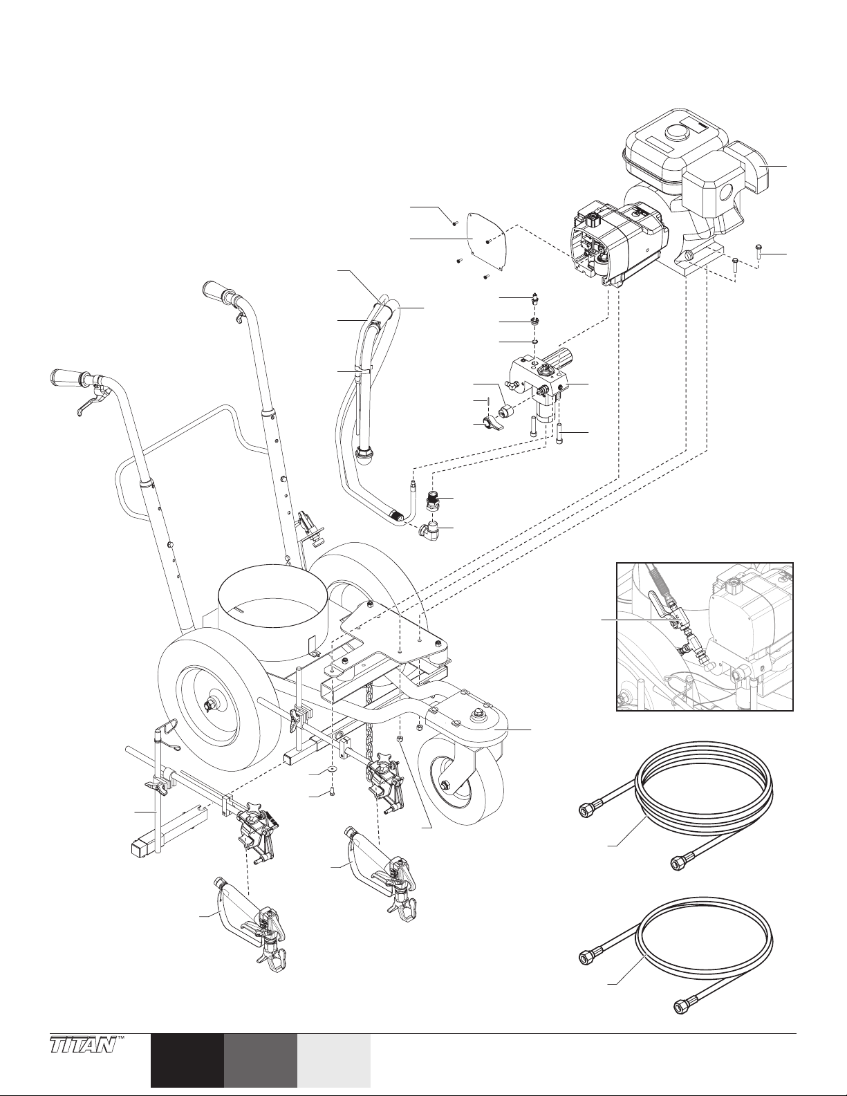
Parts List • Liste de pièces • Lista de piezas
2
1
Main Assembly • Assemblage principal • Conjunto principal
11
14
15
28
12
13
16
17
10
5
6
7
8
9
3
4
25
21
18
19
22
20
26
23
24
27
50 © Titan Tool Inc. All rights reserved.
English
EspañolFrançais
Page 51

Item
Art.
Art.
1 -------- Drive assembly Assemblage d’entraînement Conjunto de transmisión 1
2 0509550 Hex screw Clé hexagonale Tornillo hexagonal 4
3 0290513A Fluid section assembly (includes
4 704-117 Fluid section bolt Boulon du tronçon d’acheminement Perno de la sección de líquido 2
5 0551112 Transducer assembly Assemblage du transducteur Junta del transductor 1
6 0555256 Transducer adapter Adaptateur du transducteur Adaptador del transductor 1
7 0509585 Transducer gasket Joint statique du transducteur Junta del transductor 1
8 700-252 Cam base Came Base de la leva 1
9 700-759 Groove pin Goupille rigide cannelée Pasador de ranura 1
10 700-697 PRIME/SPRAY knob Bouton PRIME/SPRAY Perilla PRIME/SPRAY 1
11 770-685 Front cover screw Vis du couvercle avant Tornillos de la cubierta delantera 4
12 0555296 Front cover Couvercle avant Cubierta delantera 1
13 103-842A Siphon tube Tube de siphon Tubo de sifón 1
14 700-742 Tie wrap Attache à tête d’équerre Arrollamiento de unión 3
15 0290463A Return tube Tube de retour Tubo de retorno 1
16 200-556 Adapter Adaptateur Adaptor 1
17 0509727 90º tting Raccord de 90º Conector de 90º 1
18 763-549 Nut Écrou Tuerca 4
19 756-090 Washer Rondelle Arandela 1
20 862-436 Screw Vis Tornillo 1
21 0290514A Cart assembly (1-gun) Chariot (1-pistolet) Conjunto del carro (1-pistola) 1
22 0290532A Gun holder assembly - 2-gun
23 581-092 Spray gun Pistolet Pistola 1
24 581-092 Spray gun - 2-gun only Pistolet - 2-pistolet seulement Pistola - 2-pistola solamente 1
25 0290531A Valve assembly - 2-gun only Clapet antiretour - 2-pistolet seulement Conjunto de la válvula - 2-pistola
26 316-505A 50’ spray hose Flexible de pulvérisation de 15 m Manguera de 15 m 1
27 316-533 6’ spray hose - 2 gun only Flexible de pulvérisation de 2 m - 2-pistolet
28 730-334 Clamp Serrage Abrazadera 1
Part No.
Nº de piéce
Pieza No.
0290515A Cart assembly (2-gun) Chariot (2-pistolet) Conjunto del carro (2-pistola) 1
English
Description
items 5-10)
only
Français
Description
Assemblage du tronçon d’acheminement
(inclut les articles 5 á 10)
Ensemble de support à pistolet - 2-pistolet
seulement
seulement
Español
Descripción
Conjunto de la sección de líquido
(incluye los elementos 5-10)
Conjunto del soporte de la pistola 2-pistola solamente
solamente
Manguera de 2 m - 2-pistola
solamente
Qty.
Qte.
Cant.
1
1
1
1
© Titan Tool Inc. All rights reserved. 51
Español Français
English
Page 52
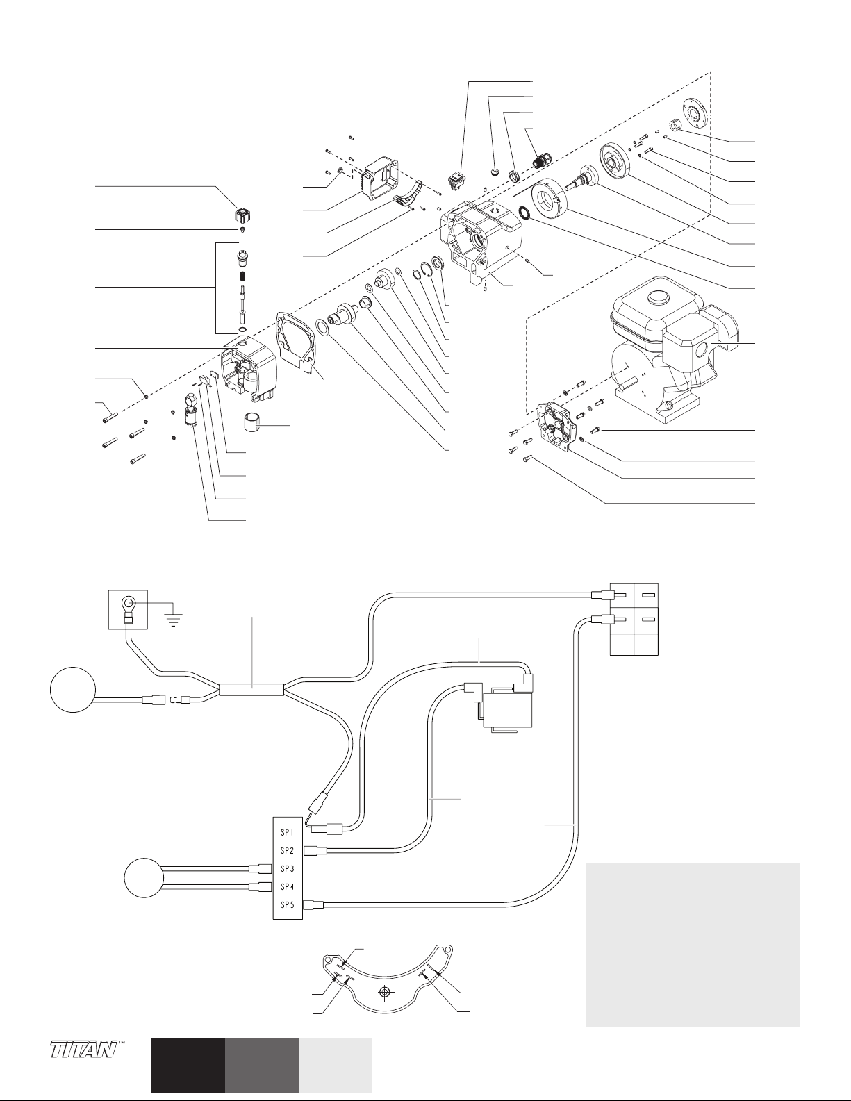
SP5
SP1
Drive Assembly • Assemblage d’entraînement • Conjunto de transmisión
22
1
2
3
4
5
6
7
8
9
10
23
24
25
26
11
12
46
13
14
15
16
17
18
19
20
21
27
28
29
30
31
32
33
34
35
36
37
38
39
40
41
42
43
44
45
Electrical Schematic • Schéma de raccordement électrique • Esquema eléctrico
P/N 0290178
P/N 759-497
Black
Noir
Negro
Motor
Moteur
Motor
Conjunto de la inducción del embrague
Pink
Rose
Rosado
Clutch eld
Champ de l’embrayage
White
Blanc
Blanco
Relay
Relais
Relé
SP3
White
Blanc
Blanco
Black
Noir
Negro
SP4
P/N
0295490
Microswitch
Microcommutateur
Microinterruptor
P/N 759-498
759-496
Relay / Relais / Relé
P/N 0295451
SP2
ON/OFF switch
Interrupteur
Interruptor
P/N 9850936
NOTE: All electrical work should
be performed by a Titan
authorized service center.
NOTA : Tous les travaux électriques
doivent être eectués par
un centre de service autorisé
de Titan.
NOTA: Un centro de servicio
técnico autorizado de Titan
debe realizar todos los
trabajos eléctricos.
52 © Titan Tool Inc. All rights reserved.
English
EspañolFrançais
Page 53

Item
Art.
Art.
1 700-771 Pressure control knob Bouton de régulation de la pression Perilla de control de presión 1
2 0509219 Screw Vis Tornillo 1
3 0555928 Pressure control assembly Commande de la pression Conjunto de control de presión 1
4 0555929 Pump housing assembly (includes
5 0509541 Lock washer Rondelle de blocage Arandela de seguridad 4
6 0555264 Pump housing screw Vis du corps de la pompe Tornillo de la carcasa de la bomba 4
7 03662 Microswitch insulator Isolateur de microcommutateur Aislante del microinterruptor 1
8 0295490 Microswitch Microcommutateur Microinterruptor 2
9 9800604 Microswitch screw Vis du microcommutateur Tornillo del microinterruptor 2
10 704-301A Slider assembly Coulisseau Conjunto deslizante 1
11 700-689 Bushing Manchon Buje 1
12 0555294 Gear housing gasket Joint statique du carter d’engrenage Junta de la carcasa de engranajes 1
13 750-015 Bearing Palier Rodamiento 1
14 750-016 Snap ring Circlip Anillo de resorte 1
15 730-144 Small snap ring Petit circlip Anillo de resorte pequeño 1
16 700-688 Thrust washer Rondelle de butée Arandela de empuje 1
17 730-167A Output gear assembly Engrenage de sortie Conjunto de engranajes de salida 1
18 700-514 Thrust washer Rondelle de butée Arandela de empuje 1
19 730-088 Cylindrical thrust washer Rondelle de butée cylindrique Arandela de empuje cilíndrica 1
20 0555931 Crankshaft assembly Vilebrequin Conjunto de cigüeñal 1
21 700-680 Thrust washer Rondelle de butée Arandela de empuje 1
22 700-139 Heat sink cover screw Vis du couvercle du dissipateur de chaleur Tornillo de la cubierta de disipador de calor 4
23 704-281 Plug Bouchon Tapón 1
24 0551523 Heat sink cover plate (includes
25 0295451 Relay Relais Relé 1
26 0551495 Relay screw Vis du relais Tornillo del relé 3
27 9850936 ON/OFF switch Interrupteur MARCHE/ARRÊT Interruptor ON/OFF 1
28 764-018 Plug Bouchon Tapón 1
29 765-087 Lock nut Écrou de bloçage Tuerca de bloqueo 1
30 765-063 Strain relief Allégement de la souche De liberación de tensión
31 763-525 Set screw Vis pression Tornillo de jación 4
32 0555017 Clutch armature assembly Armature de l’embrayage Conjunto de la armadura del embrague 1
33 763-550 Taper lock bushing (includes item
34 763-566 Taper lock bushing screw Vis du manchon conique fendu Tornillo del buje de sujeción cónico 2
35 755-218 Clutch rotor socket screw Vis à tête creuse du rotor de l’embrayage Tornillo de cabeza hueca hexagonal del rotor
36 755-215 Lock washer Rondelle de blocage Arandela de seguridad 3
37 0555007 Clutch rotor assembly Rotor de l’embrayage Conjunto del rotor del embrague 1
38 755-201 Adapter sub assembly Adaptateur du rotor d’embrayage Subconjunto del adaptador 1
39 755-204 Clutch eld assembly Champ de l’embrayage Conjunto de la inducción del embrague 1
40 730-172 Seal Joint d’étanchéité Sello 1
41 750-200 Engine Moteur Motor 1
42 0555186 12 point screw Vis à 12 points Tornillo de 12 puntos 4
43 860-002 Lock washer Rondelle de blocage Arandela de seguridad 4
44 0555288 Clutch housing Carter d’embrayage Carcasa del embrague 1
45 0509538 Screw Vis Tornillo 4
46 0555934 Gear housing assembly (includes
Part No.
Nº de piéce
Pieza No.
English
Description
item 12)
items 22 and 23)
34)
items 13, 14 and 40)
Français
Description
Corps de la pompe (inclut l’article 12) Conjunto de la carcasa de la bomba (incluye
Couvercle dissipateur de chaleur (inclut
l’articles 22-23)
Manchon conique fendu (inclut l’article 34) Buje de sujeción cónico (incluye el elemento
Carter d’engrenage (inclut les articles 13, 14
et 40)
Español
Descripción
el elemento 12)
Placa de la cubierta de disipador de calor
(incluye el elemento 22-23)
34)
del embrague
Conjunto de la carcasa de engranajes
(incluye los elementos 13, 14 y 40)
Qty.
Qte.
Cant.
1
1
1
3
© Titan Tool Inc. All rights reserved. 53
Español Français
English
Page 54
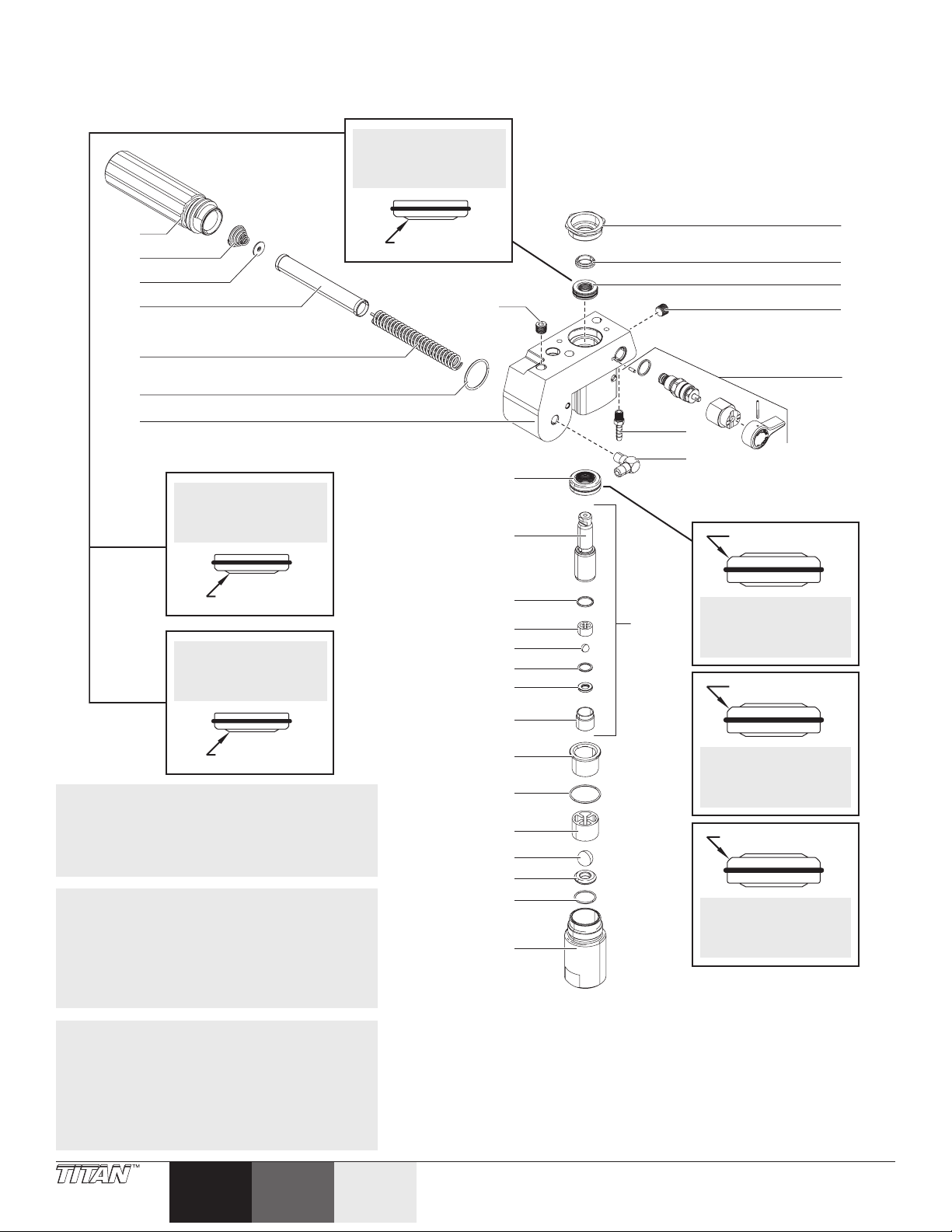
Fluid Section Assembly • Tronçon d’acheminement • Conjunto de la sección de líquido
1
23
2
3
4
5
6
7
8
9
10
11
12
13
14
15
16
17
18
19
20
21
22
24
31
25
26
27
28
29
30
Large Beveled Edge
Install upper packing
with raised lip
facing down.
Raised Lip
Install lower packing
with large beveled
edge facing up.
Grand bord biseauté
La grand bord biseauté
doivent être vers le haut.
Borde biselado de grande
Instale la empaquetadura
inferior con borde de
grande biselado hacia
arriba.
La partie surélevée
supérieur doivent être
vers le bas.
Partie surélevée
Instale la empaquetadura
superior con el reborde
levantado puntando
hacia abajo.
Reborde levantado
NOTE: When repacking the uid section, make
sure the raised lip on the bottom of the
lower packing is fully outside the packing
around the piston rod after insertion of
the piston rod.
NOTA : Au moment de procéder au regarnissage
du tronçon d’acheminement,
s’assurer que la lèvre élevée au fond
de la garniture inférieure se trouve
complètement à l’extérieur de la
garniture autour de la tige du piston
après l’insertion de la tige du piston.
NOTA: Cuando vuelva a colocar la
empaquetadura de la sección de líquido,
asegúrese de que el labio elevado de
la parte inferior de la empaquetadura
inferior esté completamente fuera de la
empaquetadura alrededor de la biela del
pistón después de la inserción de la biela
del pistón.
54 © Titan Tool Inc. All rights reserved.
English
EspañolFrançais
Page 55

Item
Art.
Art.
1 704-252 Filter housing Boîtier du ltre Carcasa del ltro 1
2 730-083 Filter spring Ressort du ltre Resorte del ltro 1
3 702-251 Adapter Adaptateur Adaptador 1
4 730-067 Filter Filtre Filtro 1
5 757-105 Spring Ressort Resorte 1
6 704-297 Seal Joint d’étanchéité Sello 1
7 0551681 Fluid section housing Logement du tronçon d’acheminement Carcasa de la sección de líquido 1
8 0507274A Lower packing Garniture d’étanchéité inférieure Empaquetadura inferior 1
9 800-452 Piston rod Tige de piston Biela del pistón 1
10 800-348 Outlet valve seal Joint d’étanchéité de la soupape de
11 800-441 Outlet cage Cage de refoulement Jaula de salida 1
12 9841502 Outlet ball Bille de la soupape de refoulement Bola de salida 1
13 0507454 Nylon washer Rondelle de nylon Arandela de nylon 1
14 0294516 Outlet valve seat Siege de la soupape de refoulement Asiento de la válvula de salida 1
15 800-336 Outlet valve retainer Organe de retenu de la soupape de
16 0555002 Bushing Manchon Buje 1
17 762-103 PTFE O-ring Joints toriques de PTFE Junta tórica de PTFE 1
18 800-442 Inlet cage Cage d’admission Jaula de entrada 1
19 51519 Inlet cage ball Bille de la cage d’admission Bola de la jaula de entrada 1
20 00310 Seat Siège Asiento 1
21 762-058 PTFE O-ring Joints toriques de PTFE Junta tórica de PTFE 1
22 0555003 Inlet valve housing Logement du clapet de pied Carcasa de la válvula de retención 1
23 227-028 Plug Bouchon Tapón 1
24 705-104 Retaining nut Écrou de retenue Tuerca de retención 1
25 705-105 Upper piston guide Guidage du piston supérieur Guía del pistón superior 1
26 0507273A Upper packing Garniture d’étanchéité supérieure Empaquetadura superior 1
27 227-028 Plug Bouchon Tapón 1
28 700-258 PRIME/SPRAY valve assembly Soupape PRIME/SPRAY Conjunto de la válvula PRIME/SPRAY 1
29 193-200 Return tube tting Raccord du tube de retour Conexión del tubo de retorno 1
30 12440 Outlet tting Raccord de sortie Conexión de salida 1
31 705-120A Piston assembly (includes items
Part No.
Nº de piéce
Pieza No.
0551511 Lower packing insertion tool (not
0555960 Repacking kit (includes items 8,
English
Description
9-15)
shown)
10, 12, 13, 16-17, 19, 21, 25 and
26)
Français
Description
refoulement
refoulement
Piston (inclut les articles 9 à 15) Conjunto del pistón (incluye los
Outil d’insertion de garniture d’étanchéité
inférieure (non aché)
Trousse de garnitures (inclut les articles 8,
10, 12, 13, 16-17, 19, 21, 25 et 26)
Español
Descripción
Sello de la válvula de salida 1
Retén de la válvula de salida 1
elementos 9 a 15)
Herramienta de inserción de la
empaquetadura inferior (no se muestra)
Juego de empaquetaduras (incluye el
elementos 8, 10, 12, 13, 16-17, 19, 21, 25
y 26)
Qty.
Qte.
Cant.
1
1
© Titan Tool Inc. All rights reserved. 55
Español Français
English
Page 56
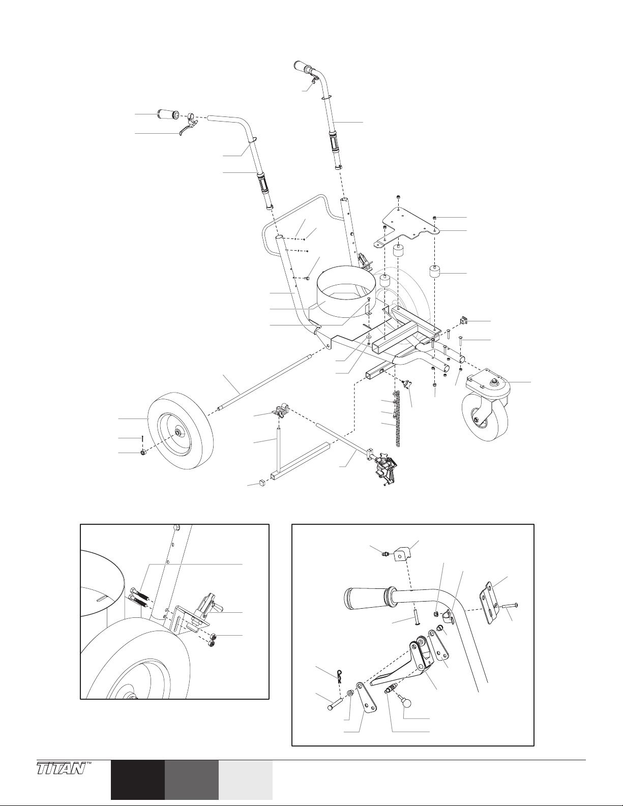
Cart Assembly • Ensemble de chariot • Conjunto de carro
42
43
44
46
45
38
47
50
43
42
51
48
49
40
39
41
4
2
1
14
19
18
20
21
22
23
24
25
26
27
28
29
30
31
32
33
34
16
15
8
9
10
13
11
12
3
17
35
36
37
5
6
7
56 © Titan Tool Inc. All rights reserved.
English
EspañolFrançais
Page 57

Item
Art.
Art.
1 424-245 Handle grip Poignée-pistolet Empuñadura de la manilla 2
2 759-215 Lever assembly - 1-gun only Levier - 1-pistolet seulement Conjunto de palanca - 1-pistola solamente 1
3 770-099 Tie wrap Attache à tête d’équerre Arrollamiento de unión 8
4 0528289A Handle assembly, left Poignée, Gauche Conjunto de manilla, Izquierda 1
5 856-002 Lock washer Rondelle de blocage Arandela de seguridad 4
6 856-921 Screw Vis Tornillo 4
7 756-091 Hex screw Vis hexagonale Tornillo hexagonal 2
8 759-474 Cart weldment Chariot Conjunto de carro 1
9 759-487 Bucket holder Support à sceau Soporte del balde 1
10 770-712 Carriage screw Vis du chariot Tornillo del carro 2
11 770-223 Washer Rondelle Arandela 2
12 770-144 Lock nut Écrou de blocage Contratuerca 2
13 759-504 Axle Essieu Eje 1
14 759-516A Rear wheel Roue arrière Rueda trasera 2
15 756-079 Cotter pin Goupille fendue Pasador de clavija 2
16 759-067 Castle nut Écrou à créneaux Tuerca almenada 2
17 759-215 Castor lever Levier de de roue pivotante Palanca de la roldana 1
18 0528288A Handle assembly, right Poignée, Droite Conjunto de manilla, Derecha 1
19 862-410 Lock nut Écrou de blocage Contratuerca 3
20 759-517 Mounting plate Plaque d’assemblage Placa de montaje 1
21 757-042 Vibration mount Montage antivibratile Almohadilla aislante 3
22 757-055 End cap Obturateur d’extrémité Capacete 1
23 759-463 Carriage screw Vis du chariot Tornillo del carro 4
24 759-508A Front wheel assembly Ensemble de la roue avant Conjunto de rueda delantera 1
25 763-549 Lock nut Écrou de blocage Contratuerca 4
26 862-410 Lock nut Écrou de blocage Contratuerca 3
27 759-306 Knob assembly Ensemble de la poignée Conjunto de la perilla 1
28 0509285 Washer Rondelle Arandela 1
29 862-436 Hex head screw Vis à tête hexagonale Tornillo de cabeza hexagonal 1
30 424-283 Grounding chain Chaînette de mise à la terre Cadena de conexión a tierra 1
31 759-329 Clamp assembly Ensemble de serrage Conjunto de abrazadera 1
32 759-188 Gun post assembly Assemblage du poteau à pistolet Conjunto del poste de la pistola 1
33 756-056 Plug Bouchon Tapón 1
34 0509171A Gun holder assembly (see separate
35 761-149 Bolt Boulon Perno 2
36 759-550A Brake assembly (see separate
37 860-502 Stop nut Écrou de blocage Tuerca de tope 2
2-Gun only • 2-Pistolet seulement • 2-Pistola solamente
38 762-058 Fitting Raccord Conector 1
39 856-744 Screw Vis Tornillo 1
40 759-034 Cotter pin Goupille fendue Pasador de clavija 1
41 759-015 Clevis pin Axe à épaulement Pasador de horquilla 1
42 424-218 Bearing, anged Palier à collerette Cojinete embridado 2
43 424-217 Lever plate Plaque de levier Placa de palanca 2
44 759-033 Knob Bouton Perilla 1
45 424-227 Cable spool selector Sélectionneur de bobine de câbles Selector de bobina del cable 1
46 424-203 Trigger Gâchette Gatillo 1
47 424-219 Mounting block Bloc de montage Bloqueo de montaje 1
48 226-001 Nut Écrou Tuerca 1
49 759-035 Lever strap Sangle de levier Abrazadera de la palanca 1
50 759-031 Control guide Guide de contrôle Guía de control 1
51 757-092 Screw Vis Tornillo 1
Part No.
Nº de piéce
English
Description
Français
Description
Español
Descripción
Pieza No.
listing)
listing)
759-499 Gun cable (not shown) Câble de pistolet (non illustré) Cable de la pistola (no se muestra) 1 / 2
779-298 Caster cable Câble de roue pivotante Cable de la roldana 1
Support à pistolet (voir liste séparée) Soporte de la pistola (consulte la lista
Frein (voir liste séparée) Conjunto de freno (consulte la lista
separada)
separada)
Qty.
Qte.
Cant.
1
1
© Titan Tool Inc. All rights reserved. 57
Español Français
English
Page 58
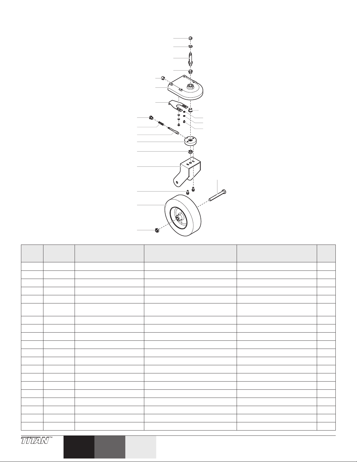
Front wheel assembly • Ensemble de roue avant • Conjunto de rueda delantera
1
2
3
4
5
6
7
4
8
9
10
11
12
13
14
17
18
19
20
15
16
Item
Art.
Art.
1 759-515 Acorn nut Écrou borgne Tuerca ciega 1
2 759-514 Spring washer Rondelle à ressort Arandela de resorte 1
3 759-428 Stem Tige Vástago 1
4 759-430 Bearing, anged Palier à collerette Cojinete embridado 2
5 779-299 Bearing Palier Cojinete 1
6 759-477A Wheel housing (includes items
7 759-506 Cable connector bracket Ferrure du connecteur de câble Soporte conector del cable 1
8 779-296 Spring retainer Rondelle de retenue de ressort Retén de resorte 1
9 756-087 Spring Ressort Resorte 1
10 779-294 Locking pin Tige de blocage Pasador de seguridad 1
11 759-511 Fork disk Disque de fourche Disco de la horquilla 1
12 759-512 Lock nut Écrou de blocage Contratuerca 1
13 759-552 Fork leg Jambe de fourche Pata de la horquilla 1
14 756-091 Hex screw Vis hexagonale Tornillo hexagonal 2
15 759-513 Wheel Roue Rueda 1
16 759-512 Lock nut Écrou de blocage Contratuerca 1
17 858-003 Flat washer Rondelle plate Arandela plana 2
18 858-002 Lock washer Rondelle de blocage Arandela de seguridad 2
19 0509219 Screw Vis Tornillo 2
20 759-459 Bolt Boulon Perno 1
Part No.
Nº de piéce
Pieza No.
English
Description
4-5)
Français
Description
Español
Descripción
Logement de roue (inclut les articles 4 et 5) Carcasa de la rueda (incluye el artículo
4-5)
Qty.
Qte.
Cant.
1
58 © Titan Tool Inc. All rights reserved.
English
EspañolFrançais
Page 59

Gun holder assembly • Ensemble de support à pistolet • Conjunto del soporte de la pistola
6
7
8
10
9
18
19
20
21
11
22
14
23
1
2
12
13
3
4
5
14
15
16
17
Item
Art.
Art.
1 759-415 Support arm Support de bras Apoyo del brazo 1
2 858-644 Screw Vis Tornillo 1
3 858-636 Screw Vis Tornillo 1
4 858-002 Washer Rondelle Arandela 2
5 ------- Gun holder assembly (includes
6 759-414 Clamp Serrage Abrazadera 1
7 0509292 Washer Rondelle Arandela 1
8 862-436 Screw Vis Tornillo 1
9 756-034 Knob Bouton Perilla 1
10 424-201 Gun holder Support à pistolet Soporte de la pistola 1
11 759-316 Clamp block Bloc de serrage Bloque de la abrazadera 1
12 756-037 Screw Vis Tornillo 1
13 858-601 Nut Écrou Tuerca 1
14 424-248 Flange bearing Palier à bride Cojinete de brida 2
15 858-653 Screw Vis Tornillo 1
16 424-249 Bearing sleeve Manchon à coussinet Manguito del cojinete 1
17 858-603 Nut Écrou Tuerca 1
18 703-079 Screw Vis Tornillo 1
19 759-056 Spring holder (short) Support de ressort (court) Portaresorte (corto) 1
20 0509781 Spring Ressort Resorte 1
21 759-057 Spring holder (long) Support de ressort (long) Portaresorte (largo) 1
22 860-936 Screw Vis Tornillo 1
23 424-202 Lever Levier Palanca 1
Part No.
Nº de piéce
Pieza No.
English
Description
items 9-23)
Français
Description
Support à pistolet (inclut l’articles 9 á 23) Soporte de la pistola (incluye el
Español
Descripción
articulos 9 a 23)
Qty.
Qte.
Cant.
1
© Titan Tool Inc. All rights reserved. 59
Español Français
English
Page 60

Gun holder assembly (2-gun only) • Ensemble de support à pistolet (2-pistolet seulement) • Conjunto del soporte de la
pistola (2-pistola solamente)
1
2
15
11
3
12
13
16
6
4
17
24
25
26
27
28
20
29
4
5
14
7
8
9
18
19
20
21
22
23
10
Item
Art.
Art.
1 424-288 Guide Guide Guía 1
2 759-329 Clamp assembly Ensemble de serrage Conjunto de abrazadera 1
3 757-089 Gun bar slide Glissière de la barre de pistolet Deslizante de la barra de la pistola 1
4 759-306 Knob assembly Ensemble de la poignée Conjunto de la perilla 2
5 757-055 Plug Bouchon Tapa 1
6 759-415 Support arm Support de bras Apoyo del brazo 1
7 858-644 Screw Vis Tornillo 1
8 858-636 Screw Vis Tornillo 1
9 858-002 Washer Rondelle Arandela 2
10 ------- Gun holder assembly (includes
11 759-414 Clamp Serrage Abrazadera 1
12 0509292 Washer Rondelle Arandela 1
13 862-436 Screw Vis Tornillo 1
14 0290534 Tube Tube Tubo
15 756-034 Knob Bouton Perilla 1
16 424-201 Gun holder Support à pistolet Soporte de la pistola 1
17 759-316 Clamp block Bloc de serrage Bloque de la abrazadera 1
18 756-037 Screw Vis Tornillo 1
19 858-601 Nut Écrou Tuerca 1
20 424-248 Flange bearing Palier à bride Cojinete de brida 2
21 858-653 Screw Vis Tornillo 1
22 424-249 Bearing sleeve Manchon à coussinet Manguito del cojinete 1
23 858-603 Nut Écrou Tuerca 1
24 703-079 Screw Vis Tornillo 1
25 759-056 Spring holder (short) Support de ressort (court) Portaresorte (corto) 1
26 0509781 Spring Ressort Resorte 1
27 759-057 Spring holder (long) Support de ressort (long) Portaresorte (largo) 1
28 860-936 Screw Vis Tornillo 1
29 424-202 Lever Levier Palanca 1
Part No.
Nº de piéce
Pieza No.
English
Description
items 15-29)
Français
Description
Support à pistolet (inclut l’articles 15 á 29) Soporte de la pistola (incluye el
Español
Descripción
articulos 15 a 29)
Qty.
Qte.
Cant.
1
60 © Titan Tool Inc. All rights reserved.
English
EspañolFrançais
Page 61
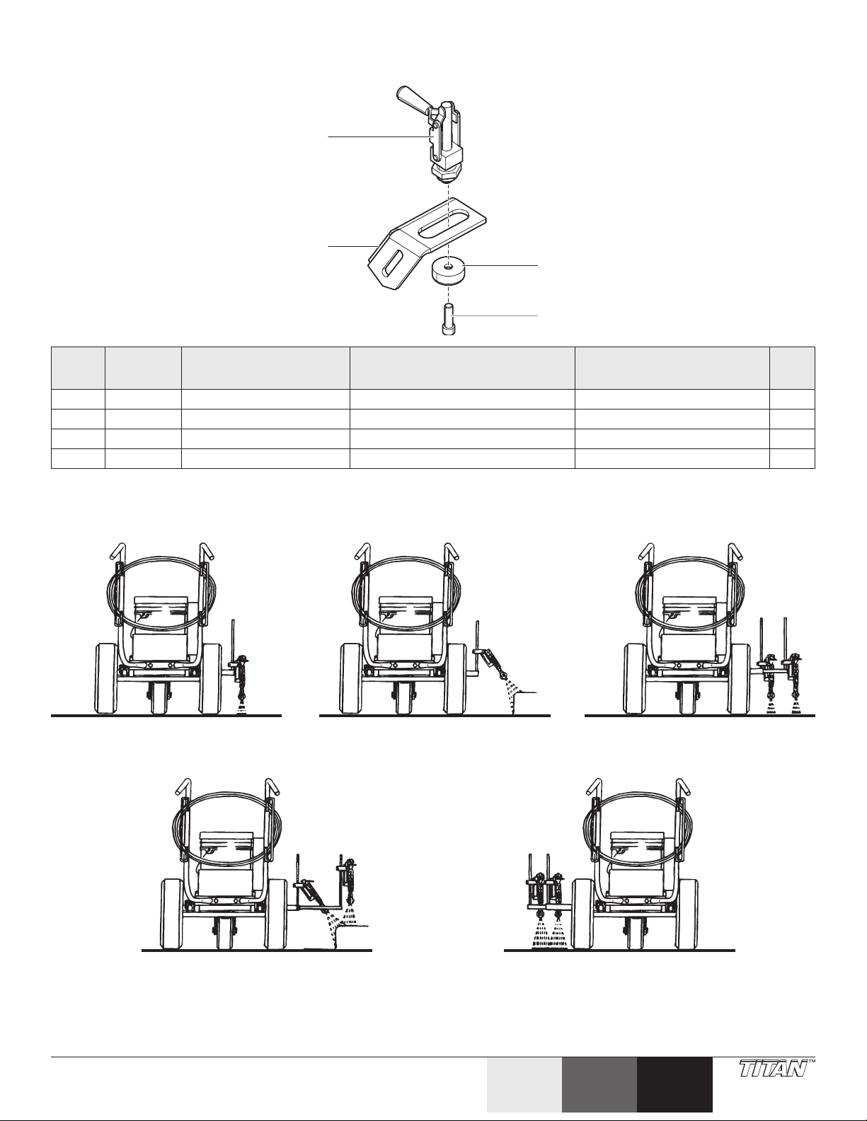
Brake assembly • Frein • Conjunto de freno
1
2
3
4
Item
Art.
Art.
1 759-549 Brake clamp Bride de frein Abrazadera del freno 1
2 759-547 Brake bracket Ferrure de frein Soporte del freno 1
3 759-548 Brake disk Disque de frein Disco de freno 1
4 730-148 Screw Vis Tornillo 1
Part No.
Nº de piéce
Pieza No.
English
Description
Français
Description
Español
Descripción
Spray Gun Positions • Positions du pistolet de pulvérisation • Posiciones de la pistola de pulverización
Single Line One Gun Curb Two Lines (2-gun unit only)
Ligne simple Bordure à un pistolet Ligne double (2-pistolet seulement)
Una línea Una pistola para la soleraDos líneas (2-pistola solamente)
Qty.
Qte.
Cant.
Two Gun Curb (2-gun unit only) Two Lines or One Wide Line (2-gun unit only)
Bordure à deux pistolets (2-pistolet seulement) Voie à ligne double ou à large ligne simple (2-pistolet seulement)
Dos pistolas para la solera (2-pistola solamente)Dos líneas o una hilera amplia (2-pistola solamente)
© Titan Tool Inc. All rights reserved. 61
Español Français
English
Page 62

Liquid Shield Plus
Cleans and protects spray systems against rust, corrosion and
premature wear. Now with -25º anti-freeze protection.
• Nettoieetprotègelessystèmesdevaporisationdelarouille,
delacorrosionetdel’usureprématurée.Maintenantavecla
protectiond’antigelde-25º.
• Limpiayprotegerlossistemasderociadocontraelóxido,la
corrosiónyeldesgasteprematuro.Ahoraconlaproteccióndel
anticongelantede-25º.
Part #
Nº de pièce
Pieza #
314-483 4 ounce bottle Bouteille de 4 oz Botella de 4
314-482 1 quart bottle Bouteille de
Description Description Descripción
onzas
Botella de 1
1 qt.
cuarto de galón
Stencil Kit • Trousse de pochoirs • Juego de esténcil —
756-135
Stencils are molded of 1/16” (1.5 mm) Durolast polyethylene. This
material is very durable and lays at on the surface being stenciled for
clean and accurate marking.
The stencil kit contains one each of the following:
• LespochoirssontmoulésdepolyéthylèneDurolastde1/16po
(1.5mm).Cematériauesttrèsrésistantetreposeàplatsurla
surfaceàpeindrepourunmarquagenetetprécis.
Latroussecomprendunpochoirdechacundesélémentssuivants:
• LasplantillasdeesténcilsemoldeandepolietilenoDurolastde
1/16”(1.5mm).Estematerialesmuyduraderoysemantiene
planoenlasuperciequesevaaestarcirparaobtenermarcas
limpiasyprecisas.
Eljuegodeesténcilcontieneunodelossiguienteselementos:
Description Description Descripción
Piston Lube
Specially formulated to prevent materials from adhering to the piston
rod, which becomes abrasive to the upper seals. Piston Lube will
break down any material that may accumulate in the oil cup and keep
it from drying.
• Spécialementformulépourempêcherlesproduitsd’adhéreràla
tigedespistons,cequitendàendommagerlesjointssupérieurs.
LePistonLubedécomposetouslesmatériauxquirisquentde
s’accumulerdanslacuvetted’égouttageetlesempêchentde
sécher.
• Formuladoespecialmenteparaevitarquelosmaterialesse
adhieranalavaradelpistón,locualesabrasivoparalossellos
superiores.ElPistonLubedegradatodomaterialquepueda
acumularseenelrecipienteyevitaqueseseque.
Part #
Description Description Descripción
Nº de pièce
Pieza #
314-481 4 ounce bottle Bouteille de 4 oz Botella de 4
onzas
314-480 8 ounce bottle Bouteille de 8 oz Botella de 8
onzas
Pointers • Pointeurs • Punteros
Part #
Nº de pièce
Pieza #
424-620 Line pointer Pointeur de ligne Puntero de línea
759-140 Laser pointer Pointeur laser Puntero de láser
Description Description Descripción
21.5“ (55 cm) Handicap
(symbol)
42” (105 cm) Straight
arrow (symbol)
42” (105 cm) Curved
arrow (symbol)
12” (30 cm) Number kit
(0 through 9)
12” (30 cm) “No
Parking” (words)
12“ (30 cm) “Fire Lane”
(words)
4“ (10 cm) “No Parking”
(words)
4“ (10 cm) “Fire Lane”
(words)
4“ (10 cm) “Visitors”
(word)
4” (10 cm) “Reserved”
(word)
stationnement pour
personne handicapée
de 21.5 po (55 cm)
(symbole)
èche droite de 42 po
(105 cm) (symbole)
èche courbe de 42 po
(105 cm) (symbole)
ensemble de chires (0
à 9) de 12 po (30 cm)
« Stationnement
interdit » de 12 po (30
cm) (mots)
« Couloir d’urgence »
de 12 po (30 cm) (mots)
« Stationnement
interdit » de 4 po (10
cm) (mots)
« Couloir d’urgence »
de 4 po (10 cm) (mots)
« Visiteurs » de 4 po (10
cm) (mot)
« Réservé » de 4 po (10
cm) (mot)
21.5“ (55 cm)
Discapacidad (símbolo)
42” (105 cm) Flecha
recta (símbolo)
42” (105 cm) Flecha
curva (símbolo)
12” (30 cm) Juego de
números (0 al 9)
12” (30 cm) “No
Parking” (No
estacionar) (palabras)
12“ (30 cm) “Fire Lane”
(Pista para protección
contra el fuego)
(palabras)
4” (10 cm) “No Parking”
(No estacionar)
(palabras)
4“ (10 cm) “Fire Lane”
(Pista para protección
contra el fuego)
(palabras)
4“ (10 cm) “Visitors”
(Visitas) (palabra)
4” (10 cm) “Reserved”
(Reservado) (palabra)
Hopper Kit • Trousse de trémie • Juego de tolva
Part #
Nº de pièce
Pieza #
759-130 12 gallon hopper Trémie de 45 l Tolva de 45 l
62 © Titan Tool Inc. All rights reserved.
Description Description Descripción
Page 63

665-3112 6”-8” (152-203 mm) .031” (.79 mm) Most trac paints — High speed. medium lm La plupart des signalisations sur route — Haute vitesse, lm
665-2508 4”-6” (102-152 mm) .025” (.64 mm) Most trac paints — Very heavy lm
665-2312 6”-8” (152-203 mm) .023” (.58 mm) Most trac paints — Medium lm La plupart des signalisations sur route - Film moyen Mayoría de pinturas para señalización vial, película media
665-2324 12”-14” (305-357 mm) .023” (.58 mm) Most trac paints — Medium lm La plupart des signalisations sur route - Film moyen Mayoría de pinturas para señalización vial, película media
665-2328 14”-16” (357-406 mm) .023” (.58 mm) Most trac paints — Medium lm La plupart des signalisations sur route - Film moyen Mayoría de pinturas para señalización vial, película media
665-2512 6”-8” (152-203 mm) .025” (.64 mm) Most trac paints — Heavy lm La plupart des signalisations sur route - Film épais Mayoría de pinturas para señalización vial, película fuerte
665-2708 4”-6” (102-152 mm) .027” (.69 mm) Most trac paints — High speed, light lm La plupart des signalisations sur route — Haute vitesse, lm
665-2712 6”-8” (152-203 mm) .027” (.69 mm) Most trac paints — Heavy lm La plupart des signalisations sur route - Film épais Mayoría de pinturas para señalización vial, película fuerte
665-2708 4”-6” (102-152 mm) .027” (.69 mm) Most trac paints — High speed, light lm La plupart des signalisations sur route — Haute vitesse, lm
665-2912 6”-8” (152-203 mm) .029” (.74 mm) Most trac paints — High speed, medium lm La plupart des signalisations sur route — Haute vitesse, lm
665-3108 4”-6” (102-152 mm) .031” (.79 mm) Most trac paints — High speed, heavy lm La plupart des signalisations sur route — Haute vitesse, lm
665-1712 6”-8” (152-203 mm) .017” (.43 mm) Most trac paints — Medium lm La plupart des signalisations sur route - Film moyen Mayoría de pinturas para señalización vial, película media
665-1902 1”-2” (25-51 mm) .019” (.48 mm) Most trac paints — Medium lm La plupart des signalisations sur route - Film moyen Mayoría de pinturas para señalización vial, película media
665-1904 2”- 4” (51-102 mm) .019” (.48 mm) Most trac paints — Heavy lm La plupart des signalisations sur route - Film épais Mayoría de pinturas para señalización vial, película fuerte
665-1908 4”-6” (102-152 mm) .019” (.48 mm) Most trac paints — Medium lm La plupart des signalisations sur route - Film moyen Mayoría de pinturas para señalización vial, película media
665-1912 6”-8” (152-203 mm) .019” (.48 mm) Most trac paints — Medium lm La plupart des signalisations sur route - Film moyen Mayoría de pinturas para señalización vial, película media
665-1920 10”-12” (255-305 mm) .019” (.48 mm) Most trac paints — Medium lm La plupart des signalisations sur route - Film moyen Mayoría de pinturas para señalización vial, película media
665-2104 2”- 4” (51-102 mm) .021” (.53 mm) Most trac paints — Medium lm La plupart des signalisations sur route - Film moyen Mayoría de pinturas para señalización vial, película media
665-2108 4”-6” (102-152 mm) .021” (.53 mm) Most trac paints — Heavy lm La plupart des signalisations sur route - Film épais Mayoría de pinturas para señalización vial, película fuerte
665-2112 6”-8” (152-203 mm) .021” (.53 mm) Most trac paints — Light lm La plupart des signalisations sur route - Film léger Mayoría de pinturas para señalización vial, película ligera
665-2124 12”-14” (305-357 mm) .021” (.53 mm) Most trac paints — Light lm La plupart des signalisations sur route - Film léger Mayoría de pinturas para señalización vial, película ligera
665-2128 14”-16” (357-406 mm) .021” (.53 mm) Most trac paints — Light lm La plupart des signalisations sur route - Film léger Mayoría de pinturas para señalización vial, película ligera
665-2308 4”-6” (102-152 mm) .023” (.58 mm) Most trac paints — Heavy lm La plupart des signalisations sur route - Film épais Mayoría de pinturas para señalización vial, película fuerte
665-1302 1”-2” (25-51 mm) .013” (.33 mm) Stencils & Athletic Courts — Light lm (use 100
665-1304 2”- 4” (51-102 mm) .013” (.33 mm) Stencils & Athletic Courts — Light lm (use 100
665-1308 4”-6” (102-152 mm) .013” (.33 mm) Stencils & Athletic Courts — Light lm (use 100
665-1502 1”-2” (25-51 mm) .015” (.33 mm) Stencils & Athletic Courts — Alkyd only, light lm Modèles et terrains de sports — Alkyd uniquement, lm léger Pistas de atletismo y plantillas, sólo alquid, película delgada
665-1504 2”- 4” (51-102 mm) .015” (.33 mm) Stencils & Athletic Courts — Light lm Modèles et terrains de sports - Film léger Pistas de atletismo y plantillas, película ligera
665-1508 4”-6” (102-152 mm) .015” (.33 mm) Stencils & Athletic Courts — Light lm Modèles et terrains de sports - Film léger Pistas de atletismo y plantillas, película ligera
665-1512 6”-8” (152-203 mm) .015” (.33 mm) Most trac paints — Medium lm La plupart des signalisations sur route - Film moyen Mayoría de pinturas para señalización vial, película media
665-1702 1”-2” (25-51 mm) .017” (.43 mm) Stencils & Athletic Courts — Alkyd only, heavy
665-1704 2”- 4” (51-102 mm) .017” (.43 mm) Most trac paints — Medium lm La plupart des signalisations sur route - Film moyen Mayoría de pinturas para señalización vial, película media
665-1708 4”-6” (102-152 mm) .017” (.43 mm) Most trac paints — Light lm La plupart des signalisations sur route - Film léger Mayoría de pinturas para señalización vial, película ligera
Tip Part #
Buse #
Punta #
Line Width
Largeur de ligne
Ancho de raya
Orice
Orice
Oricio
moyen
épais
moyen
léger
léger
La plupart des signalisations sur route — Film très épais
lm
Modèles et terrains de sports — Alkyd uniquement, lm épais Pistas de atletismo y plantillas, sólo alquid, película gruesa
mesh lter)
Modèles et terrains de sports - Film léger (ltre de 100 maille) Pistas de atletismo y plantillas, película ligera (100 mesh ltro)
Modèles et terrains de sports - Film léger (ltre de 100 maille) Pistas de atletismo y plantillas, película ligera (100 mesh ltro)
Modèles et terrains de sports - Film léger (ltre de 100 maille) Pistas de atletismo y plantillas, película ligera (100 mesh ltro)
mesh lter)
mesh lter)
Common Uses Utilisations habituelles Uso habitual
Mayoría de pinturas para señalización vial, película muy gruesa
Mayoría de pinturas para señalización vial, para altas velocidades,
película delgada
Mayoría de pinturas para señalización vial, para altas velocidades,
película delgada
Mayoría de pinturas para señalización vial, para altas velocidades,
película media
Mayoría de pinturas para señalización vial, para altas velocidades,
película gruesa
Mayoría de pinturas para señalización vial, para altas velocidades,
película media
© Titan Tool Inc. All rights reserved. 63
Page 64

Titan Tool, Inc., (“Titan”) warrants that at the time of delivery to the original purchaser for use (“End User”), the equipment covered by this warranty is free from defects in material and
workmanship. With the exception of any special, limited, or extended warranty published by Titan, Titan’s obligation under this warranty is limited to replacing or repairing without
charge those parts which, to Titan’s reasonable satisfaction, are shown to be defective within twelve (12) months after sale to the End User. This warranty applies only when the unit is
installed and operated in accordance with the recommendations and instructions of Titan.
This warranty does not apply in the case of damage or wear caused by abrasion, corrosion or misuse, negligence, accident, faulty installation, substitution of non-Titan component
parts, or tampering with the unit in a manner to impair normal operation.
Defective parts are to be returned to an authorized Titan sales/service outlet. All transportation charges, including return to the factory, if necessary, are to be borne and prepaid by
the End User. Repaired or replaced equipment will be returned to the End User transportation prepaid.
THERE IS NO OTHER EXPRESS WARRANTY. TITAN HEREBY DISCLAIMS ANY AND ALL IMPLIED WARRANTIES INCLUDING, BUT NOT LIMITED TO, THOSE OF MERCHANTABILITY AND
FITNESS FOR A PARTICULAR PURPOSE, TO THE EXTENT PERMITTED BY LAW. THE DURATION OF ANY IMPLIED WARRANTIES WHICH CANNOT BE DISCLAIMED IS LIMITED TO THE TIME
PERIOD SPECIFIED IN THE EXPRESS WARRANTY. IN NO CASE SHALL TITAN LIABILITY EXCEED THE AMOUNT OF THE PURCHASE PRICE. LIABILITY FOR CONSEQUENTIAL, INCIDENTAL OR
SPECIAL DAMAGES UNDER ANY AND ALL WARRANTIES IS EXCLUDED TO THE EXTENT PERMITTED BY LAW.
TITAN MAKES NO WARRANTY AND DISCLAIMS ALL IMPLIED WARRANTIES OF MERCHANTABILITY AND FITNESS FOR A PARTICULAR PURPOSE WITH RESPECT TO ACCESSORIES,
EQUIPMENT, MATERIALS OR COMPONENTS SOLD BUT NOT MANUFACTURED BY TITAN. THOSE ITEMS SOLD, BUT NOT MANUFACTURED BY TITAN (SUCH AS GAS ENGINES, SWITCHES,
HOSES, ETC.) ARE SUBJECT TO THE WARRANTY, IF ANY, OF THEIR MANUFACTURER. TITAN WILL PROVIDE THE PURCHASER WITH REASONABLE ASSISTANCE IN MAKING ANY CLAIM
FOR BREACH OF THESE WARRANTIES.
Material Safety Data Sheets (MSDS) are available on Titan’s website or by calling Customer Service.
Garantie
Titan Tools, inc. (« Titan ») garantit qu’au moment de la livraison à l’acheteur original (« Utilisateur »), l’appareil couvert par la présente garantie sera exempt de défauts de matériaux
et de fabrication. Les responsabilités de Titan en vertu de cette garantie se limitent au remplacement ou à la réparation sans frais des pièces dont on aura, à la satisfaction raisonnable
de Titan, démontré la défectuosité dans un délai de douze (12) mois après la date d’achat par l’Utilisateur. Cette garantie ne s’applique que si l’appareil a été installé et utilisé
conformément aux recommandations et directives de Titan.
Cette garantie ne s’applique pas dans les cas d’endommagement ou d’usure engendrés par de l’abrasion, de la corrosion, un mauvais usage, de la négligence, un accident, une
installation incorrecte, un remplacement par des composants non fournis par Titan ou toute intervention non autorisée apte à nuire au fonctionnement normal de l’appareil.
Les pièces défectueuses doivent être envoyées à un centre de service/vente Titan autorisé; les frais de transport, incluant le retour à l’usine, le cas échéant, doivent être défrayés à
l’avance par l’Utilisateur. Une fois remplacées ou réparées, les pièces seront renvoyées à ce dernier par transport prépayé.
AUCUNE AUTRE GARANTIE EXPLICITE N’EST DONNÉE. PAR LES PRÉSENTES, TITAN SE DÉGAGE DE TOUTE AUTRE GARANTIE IMPLICITE, INCLUANT, SANS TOUTEFOIS S’Y LIMITER, LES
GARANTIES DE COMMERCIABILITÉ ET D’ADAPTATION À UN USAGE PARTICULIER, DANS LES LIMITES PERMISES PAR LA LOI. LA DURÉE DES GARANTIES IMPLICITES NE POUVANT ÊTRE
DÉCLINÉES SE LIMITE À LA PÉRIODE INDIQUÉE DANS LA GARANTIE EXPLICITE. LES RESPONSABILITÉS DE TITAN NE SAURAIENT EN AUCUN CAS SE CHIFFRER À UN MONTANT SUPÉRIEUR
À CELUI DU PRIX D’ACHAT, ET CELLES RELATIVES AUX DOMMAGES CONSÉCUTIFS, ACCESSOIRES OU PARTICULIERS EN VERTU DE TOUTE GARANTIE SONT ÉGALEMENT DÉCLINÉES,
DANS LES LIMITES PERMISES PAR LA LOI.
TITAN NE DONNE AUCUNE AUTRE GARANTIE EXPLICITE ET DÉCLINE TOUTE GARANTIE IMPLICITE DE COMMERCIABILITÉ ET D’ADAPTATION À UN USAGE PARTICULIER RELATIVEMENT
AUX ACCESSOIRES, À L’ÉQUIPEMENT, AUX MATÉRIAUX OU AUX COMPOSANTS VENDUS MAIS NON FABRIQUÉS PAR ELLE; CES ÉLÉMENTS (MOTEURS À ESSENCE, COMMUTATEURS,
FLEXIBLES, ETC.) SONT PLUTÔT SOUMIS, LE CAS ÉCHÉANT, AUX GARANTIES DE LEUR FABRICANT. TITAN S’ENGAGE À OFFRIR UN SOUTIEN RAISONNABLE AUX UTILISATEURS QUI
FERONT DES RÉCLAMATIONS RELATIVES À L’INOBSERVATION DE CES GARANTIES.
Warranty
Des ches techniques de sécurité des produits (FTSS) sont disponibles sur le site Internet de Titan ou par téléphone en vous adressant au Service Client.
Garantía
Titan Tool, Inc., (“Titan”) garantiza que en el momento de la entrega al comprador original para su uso (“Usuario nal”), el equipo cubierto por esta garantía está exento de defectos
en material y fabricación. La obligación de Titan en virtud de esta garantía se limita a sustituir o reparar sin cargo las piezas que; a la entera satisfacción de Titan, demuestren estar
defectuosas dentro de doce (12) meses después de la venta al usuario nal. Esta garantía corresponde solamente cuando la unidad se instala y funciona según las recomendaciones e
instrucciones de Titan.
Esta garantía no corresponde en el caso de daños o desgaste causados por abrasión, corrosión o uso indebido, negligencia, accidente, instalación errada, sustitución de piezas con
componentes que no sean Titan o alteraciones con la unidad de tal modo que se vea afectado el funcionamiento normal.
Las piezas defectuosas deben devolverse a un centro de ventas y servicio autorizado de Titan. Todos los cargos de transporte, incluso la devolución a la fábrica, si es necesario, debe
pagarlos previamente el usuario nal. El equipo reparado o cambiado se devolverá al usuario nal con porte prepagado.
NO EXISTE NINGUNA OTRA GARANTÍA EXPRESA. TITAN DESCONOCE POR LA PRESENTE TODA OTRA GARANTÍA IMPLÍCITA INCLUSIVE ENTRE OTRAS, LAS DE COMERCIABILIDAD E
IDONEIDAD PARA UN FIN PARTICULAR, EN LA MEDIDA QUE LO PERMITA LA LEY. LA DURACIÓN DE LAS GARANTÍAS IMPLÍCITAS QUE NO PUEDEN DESCONOCERSE SE LIMITA AL PLAZO
ESPECIFICADO EN LA GARANTÍA EXPRESA. EN NINGÚN CASO EXCEDERÁ LA RESPONSABILIDAD DE TITAN EL MONTO DEL PRECIO DE COMPRA. LA RESPONSABILIDAD CIVIL POR
DAÑOS Y PERJUICIOS RESULTANTES, FORTUITOS O ESPECIALES BAJO TODA GARANTÍA QUEDA EXCLUIDA EN LA MEDIDA QUE LO PERMITA LA LEY.
TITAN NO OFRECE GARANTÍAS Y DESCONOCE TODA GARANTÍA IMPLÍCITA DE COMERCIABILIDAD E IDONEIDAD PARA UN FIN PARTICULAR REFERENTE A ACCESORIOS, EQUIPO,
MATERIALES O COMPONENTES VENDIDOS PERO NO FABRICADOS POR TITAN. AQUELLOS ARTÍCULOS VENDIDOS, PERO NO FABRICADOS POR TITAN (COMO LOS MOTORES DE
GAS, INTERRUPTORES, MANGUERAS, ETC.) ESTÁN PROTEGIDOS POR LA GARANTÍA DE SU PROPIO FABRICANTE, SI LA HAY. TITAN PROPORCIONARÁ AL COMPRADOR ASISTENCIA
RAZONABLE PARA EFECTUAR RECLAMOS EN CASO DE INCUMPLIMIENTO DE ESTAS GARANTÍAS.
Las Hojas de Datos de Seguridad (Material Safety Data Sheets - MSDS) se encuentran disponibles en el sitio web de Titan o llamando al Servicio al Cliente.
United States Sales & Service
Phone:
1-800-526-5362
Fax:
1-800-528-4826
1770 Fernbrook Lane
Plymouth, MN 55447
www.titantool.com
International Sales
international@titantool.com
Fax: 1-763-519-3509
1770 Fernbrook Lane
Plymouth, MN 55447
64 © Titan Tool Inc. All rights reserved.
English
EspañolFrançais
 Loading...