

Page 1
Owner’s Manual
Notice d’utilisation
Manual del Propietario
Do not use this equipment
before reading this manual!
SPEEFLO
PowrLiner 850
Model Number
0290005
Register your product online at:
www.titantool.com
Proper registration will serve as proof of purchase in the event your
original receipt becomes misplaced or lost.
Serial Number _ _ _ _ _ _ _ _ _ _
US Patent Nos. D550,328 D550,329 7,886,876
NOTE: This manual contains important
warnings and instructions. Please
read and retain for reference.
0412 • © Titan Tool Inc. All Rights Reserved. Form No. 0293747F
Page 2
Important Safety Information · Read all safety information before
operating the equipment. SAVE THESE INSTRUCTIONS.
Indicates a hazardous situation which, if not
avoided, could result in death or serious injury.
a) Toreducetherisksofreorexplosion,electrical
shock and the injury to persons, read and understand
all instructions included in this manual. Be familiar
with the controls and proper usage of the equipment.
b)WARNING-Toreducetheriskofreor
explosion:
1. Do not spray ammable or combustible
materials near an open ame, pilot lights or sources of ignition
such as hot objects, cigarettes, motors, electrical equipment
and electrical appliances. Avoid creating sparks from
connecting and disconnecting power cords.
2. For units intended for use with only water-based materials
— Do not spray or clean with ammable liquids. For use with
water-based liquids only.
3. For units intended for use with only water-based or mineral
spirit-type materials with a minimum ash point of 21ºC
(69.8ºF) — Do not spray or clean with liquids having a
ash point of less than 21ºC (69.8ºF). Flash point is the
temperature at which a uid can produce enough vapor to
ignite.
4. Paint or solvent owing through the equipment is able to result
in static electricity. Static electricity creates a risk of re or
explosion in the presence of paint or solvent fumes. All parts
of the spray system, including the pump, hose assembly,
spray gun and objects in and around the spray area shall
be properly grounded to protect against static discharge
and sparks. Use only conductive or grounded high-pressure
airless paint sprayer hoses specied by the manufacturer.
5. Verify that all containers and collection systems are grounded
to prevent static discharge.
6. Connect to a grounded outlet and use grounded extension
cords (electric models only). Do not use a 3 to 2 adapter.
7. Do not use a paint or solvent containing halogenated
hydrocarbons. Such as chlorine, bleach mildewcide,
methylene chloride and trichloroethane. They are not
compatible with aluminum. Contact the coating supplier about
compatibility of material with aluminum.
8. Keep spray area well ventilated. Keep a good supply of fresh
air moving through the area to keep the air within the spray
area free from accumulation of ammable vapors. Keep
pump assembly in well ventilated area. Do not spray pump
assembly.
9. Do not smoke in the spray area.
10. Do not operate light switches, engines, or similar spark
producing products in the spray area.
11. Keep area clean and free of paint or solvent containers, rags,
and other ammable materials.
12. Know the contents of the paint and solvents being sprayed.
Read all Material Safety Data Sheets (MSDS) and container
labels provided with the paints and solvents. Follow the paint
and solvent manufacture’s safety instructions.
13. Place pump at least 25 feet (7.62 meters) from the spray
object in a well ventilated area (add more hose if necessary).
Flammable vapors are often heavier than air. Floor area must
be extremely well ventilated. The pump contains arcing parts
that emit sparks and can ignite vapors.
14. Plastic can cause static sparks. Never hang plastic to
enclose spray area. Do not use plastic drop cloths when
spraying ammable material.
15. Fire extinguisher equipment shall be present and working.
c) WARNING - To reduce the risk of skin
injection:
1. Do not aim the gun at, or spray any person or animal.
2. Keep hands and other body parts away from the discharge.
For example, do not try to stop leaks with any part of the
body.
3. Always use the nozzle tip guard. Do not spray without the
nozzle tip guard in place.
4. Only use a nozzle tip specied by the manufacturer.
5. Use caution when cleaning and changing nozzle tips. In the
case where the nozzle tip clogs while spraying, ALWAYS lock
gun trigger, shut pump off, and release all pressure before
servicing, cleaning tip or guard, or changing tip. Pressure
will not be released by turning off the motor. The PRIME/
SPRAY valve or pressure bleed valve must be turned to their
appropriate positions to relieve system pressure. Refer to
PRESSURE RELIEF PROCEDURE described in the pump
manual.
NOTE: If necessary, loosen the gun holder clamp knob and
then engage the spray gun trigger lock.
6. Do not leave the unit energized or under pressure while
unattended. When the unit is not in use, turn off the unit and
relieve the pressure in accordance with the manufacturer’s
instructions.
7. High-pressure spray is able to inject toxins into the body and
cause serious bodily injury. In the event that injection occurs,
seek medical attention immediately.
8. Check hoses and parts for signs of damage, a leak can inject
material into the skin. Inspect hose before each use. Replace
any damaged hoses or parts.
9. This system is capable of producing 3000 PSI / 207 Bar. Only
use replacement parts or accessories that are specied by the
manufacturer and that are rated a minimum of 3000 PSI. This
includes spray tips, nozzle guards, guns, extensions, ttings,
and hose.
10. Always engage the trigger lock when not spraying. Verify the
trigger lock is functioning properly. If necessary, loosen the
gun holder clamp knob and then engage the spray gun trigger
lock.
11. Verify that all connections are secure before operating the
unit.
12. Know how to stop the unit and bleed pressure quickly. Be
thoroughly familiar with the controls. Pressure will not be
released by turning off the motor. The PRIME/SPRAY valve
or pressure bleed valve must be turned to their appropriate
positions to relieve system pressure. Refer to PRESSURE
RELIEF PROCEDURE described in the pump manual.
13. Always remove the spray tip before ushing or cleaning the
system.
NOTE TO PHYSICIAN:
Injection into the skin is a traumatic injury. It is important to
treat the injury as soon as possible. DO NOT delay treatment
toresearchtoxicity.Toxicityisaconcernwithsomecoatings
injected directly into the blood stream. Consultation with
a plastic surgeon or reconstructive hand surgeon may be
advisable.
2 © Titan Tool Inc. All rights reserved.
English
Page 3
Important Safety Information · Read all safety information before
operating the equipment. SAVE THESE INSTRUCTIONS.
d) WARNING - To reduce the risk of injury:
1. Always wear appropriate gloves, eye protection, clothing
and a respirator or mask when painting. Hazardous vapors
– Paints, solvents, insecticides, and other materials can be
harmful if inhaled or come in contact with body. Vapors can
cause severe nausea, fainting or poisoning.
2. Wear ear protection. This unit can produce noise levels
above 85 dB(A).
3. Do not operate or spray near children. Keep children away
from equipment at all times.
4. Do not overreach or stand on an unstable support. Keep
effective footing and balance at all times.
5. Stay alert and watch what you are doing.
6. Do not operate the unit when fatigued or under the inuence
of drugs or alcohol.
7. Do not kink or over-bend the hose. Airless hose can develop
leaks from wear, kinking and abuse. A leak can inject
material into the skin.
8. Do not expose the hose to temperatures or pressures in
excess of those specied by manufacturer.
9. Do not use the hose as a strength member to pull or lift the
equipment.
10. Use lowest possible pressure to ush equipment.
11. Follow all appropriate local, state and national codes
governing ventilation, re prevention and operation.
12. The United States Government Safety Standards have
been adopted under the Occupational Safety and Health
Act (OSHA). These standards, particularly part 1910 of
the General Standards and part 1926 of the Construction
Standards should be consulted.
13. Before each use, check all hoses for cuts, leaks, abrasion
or bulging of cover. Check for damage or movement
of couplings. Immediately replace hose if any of those
conditions exist. Never repair a paint hose. Replace with a
conductive high-pressure hose.
14. Do not spray outdoors on windy days.
15. Always unplug cord from outlet before working on equipment
(electric models only).
• Do not overll the fuel tank. After refueling, make sure the
tank cap is closed properly and securely.
• Be careful not to spill fuel when refueling. Fuel vapor or
spilled fuel may ignite. If any fuel is spilled, make sure the
area is dry before starting the engine.
• Never run the engine in an enclosed or conned area.
Exhaust contains poisonous carbon monoxide gas; exposure
may cause loss of consciousness and may lead to death.
• The mufer becomes very hot during operation and remains
hot for a while after stopping the engine. Be careful not to
touch the mufer while it is hot. To avoid severe burns or re
hazards, let the engine cool before transporting it or storing it
indoors.
• Never ship/transport unit with gasoline in the tank.
• Never dispose of the unit when it is lled with oil or gas.
Follow all appropriate local, state, and national regulations
when disposing of the unit.
Specications
Gallons per minute (GPM) ............. 0.33 (1.25 LPM)
Maximum tip size ........................... 0.019” — Trafc marking
0.023” — Field marking
Maximum pressure ........................ 3000 PSI (20.7 MPa)
Power ......................................... 37.7cc, 4-stroke gas engine
Fuel capacity .................................0.17 US gallons (0.65 L)
Weight ......................................... 65 lbs. (29.5 kg)
Inlet paint lter ............................... 10 mesh “rock catcher”
Hose connection ............................ 1/4” NPS(M)
Line width range ............................ 2”–12” (5–30 cm)
Dimensions .................................... 41” L (104 cm)
21” W (53.3 cm)
32” H (81.3 cm)
Gasoline Engine Safety
Theengineexhaustfromthisunitcontainschemicals
known to the State of California to cause cancer, birth
defects, or other reproductive harm.
• Gas engines are designed to give safe and dependable
service if operated according to instructions. Read and
understand the engine Owner’s Manual before operating the
engine. Failure to do so could result in personal injury or
equipment damage.
• To prevent re hazards and to provide adequate ventilation,
keep the engine at least 1 meter (3 feet) away from buildings
and other equipment during operation. Do not place
ammable objects close to the engine.
• To prevent re or explosion hazard, avoid spraying or
splashing any ammable solvent near the engine.
• Children and pets must be kept away from the area of
operation due to a possibility of burns from hot engine
components or injury from any equipment the engine may be
used to operate.
• Know how to stop the engine quickly, and understand the
operation of all controls. Never permit anyone to operate the
engine without proper instructions.
• Gasoline is extremely ammable and is explosive under
certain conditions.
• Refuel in a well-ventilated area with the engine stopped. Do
not smoke or allow ames or sparks in the refueling area or
where gasoline is stored.
© Titan Tool Inc. All rights reserved. 3
English
Page 4
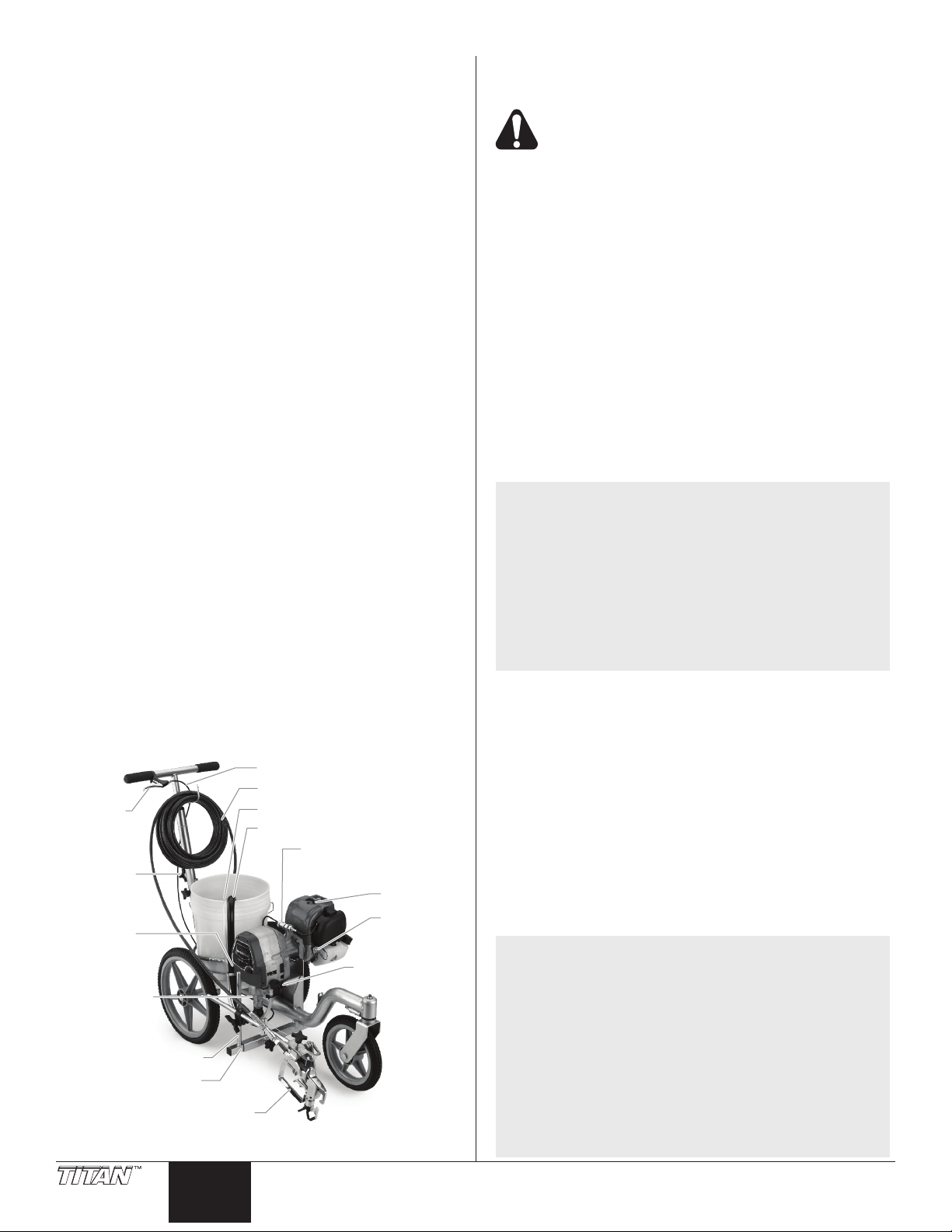
Table of Contents
Spray
lever
Outlet
fitting
Handle
adjustment
knob
PRIME/SPRAY
Knob
Engine
shutoff
switch
Engine
DirectLink
pressure control
knob
Return hose
Gun cable
Airless spray hose
Siphon tube
Gun
support bar
Airless spray gun
Gun riser
Sureflo™
valve
* Pail not included.
Safety Instructions ................................................................... 2
Specications ........................................................................... 3
General Description ................................................................. 4
Operation ................................................................................... 4
Fueling................................................................................. 4
Operator Controls ................................................................ 4
Setup ................................................................................... 5
Preparing to Paint................................................................ 6
Painting ............................................................................... 7
Pressure Relief Procedure .................................................. 8
Clearing a Clogged Tip........................................................ 8
Changing a Spray Tip.......................................................... 8
Stenciling ............................................................................. 8
Operating the Front Caster.................................................. 8
Cleanup .....................................................................................9
Special Cleanup .................................................................. 9
Cleaning/Replacing the Gun Filter .................................... 10
Cleaning the Sureo Valve Assembly ............................... 10
Maintenance ............................................................................ 10
General Repair and Service Notes.................................... 10
Adjusting the Trigger Tension ........................................... 10
Maintaining the Engine ...................................................... 11
Safety Shut-Off Switch ...................................................... 11
Replacing the PRIME/SPRAY Valve ................................. 11
Servicing the Fluid Section ................................................ 12
Troubleshooting ..................................................................... 14
Parts Listings .......................................................................... 44
Main Assembly .................................................................. 44
Drive Assembly ................................................................. 46
Cart Assembly ................................................................... 48
Gun Holder Assembly ....................................................... 50
Spray Gun ......................................................................... 51
Electrical Schematic .......................................................... 52
Labels ................................................................................ 52
Accessories ............................................................................53
Product Registration .............................................................. 56
Limited Warranty .................................................................... 56
General Description
This airless line striper is a precision power tool used to spray
many types of material for many types of applications including
parking lots, curbs, and athletic elds. Read and follow this
instruction manual carefully for proper operating instructions,
maintenance, and safety information.
IMPORTANT : In order to prevent spills, make sure the pail is
covered whenever the unit is moving.
Operation
Fueling (gas engine)
Gasolineisextremelyflammableandisexplosive
under certain conditions.
• ALWAYS turn the engine off before refueling.
• Refuel in a well-ventilated area.
• Do not smoke or allow ames or sparks in the refueling
area or where gasoline is stored.
• Do not overll the fuel tank. After refueling, make sure the
tank cap is closed properly and securely.
• Be careful not to spill fuel when refueling. Spilled fuel or
fuel vapor may ignite. If any fuel is spilled, make sure the
area is dry before starting the engine.
• Avoid repeated or prolonged contact with skin or breathing
of vapor.
• Keep out of the reach of children.
FuelSpecications
• Use automotive gasoline that has a pump octane number
of 86 or higher, or that has a research octane number of
91 or higher. Use of a lower octane gasoline can cause
persistent “pinging” or heavy “spark knock” (a metallic
rapping noise) which, if severe, can lead to engine
damage.
NOTE: If “spark knock” or “pinging” occurs at a steady
engine speed under normal load, change brands
of gasoline. If spark knock or pinging persists,
consult an authorized dealer of the engine
manufacturer. Failure to do so is considered
misuse, and damage caused by misuse is not
covered by the engine manufacturer’s limited
warranty.
Occasionallyyoumayexperiencelightspark
knock while operating under heavy loads. This
is no cause for concern, it simply means your
engineisoperatingefciently.
• Unleaded fuel produces fewer engine and spark plug
deposits and extends the life of the exhaust system
components.
• Never use stale or contaminated gasoline or an oil/
gasoline mixture. Avoid getting dirt, dust, or water in the
fuel tank.
4 © Titan Tool Inc. All rights reserved.
English
Gasolines Containing Alcohol
If you decide to use a gasoline containing alcohol (gasohol), be
sure its octane rating is at least as high as that recommended
by the engine manufacturer. There are two types of “gasohol”:
one containing ethanol, and the other containing methanol. Do
not use gasohol that contains more than 10% ethanol. Do not
use gasoline containing methanol (methyl or wood alcohol)
that does not also contain co-solvents and corrosion inhibitors
for methanol. Never use gasoline containing more than 5%
methanol, even if it has co-solvents and corrosion inhibitors.
NOTE: Fuel system damage or engine performance
problems resulting from the use of fuels that
contain alcohol is not covered under the
warranty. The engine manufacturer cannot
endorse the use of fuels containing methanol
since evidence of their suitability is incomplete at
this time.
Before buying gasoline from an unfamiliar
station,trytondoutifthegasolinecontains
alcohol.Ifitdoes,conrmthetypeand
percentage of alcohol used. If you notice any
undesirable operating characteristics while using
a gasoline that contains alcohol, or one that you
think contains alcohol, switch to a gasoline that
you know does not contain alcohol.
Page 5
Operator Controls
Spray
lever
Shutoff
switch
PRIME/SPRAY
knob
DirectLink
Sureflo
Valve
Handle
adjustment
knob
Handle
knob
Support
bar knob
Gun riser
clamp
SPRAY
PRIME
The following section describes the operator controls on the
spray gun and line striper.
Spray Gun Trigger Lock
Engage the trigger lock whenever
the gun is not in use.
The gun is locked when the trigger
lock is at a 90º angle (perpendicular
to the trigger in either direction).
NOTE: If necessary, loosen the gun holder clamp knob
Spray Lever
The spray lever is located on
the cart handle. The spray lever
controls the trigger on the spray
gun.
Fully pulling the spray lever triggers
the spray gun. While striping, the
spray lever should be fully pulled for
proper operation.
DirectLink™
Spraying pressure is
determined by the motor
throttle.
The throttle is regulated by
adjusting the DirectLink™
pressure control knob. The
higher the throttle, the higher
the spraying pressure.
PRIME/SPRAY Knob
The PRIME/SPRAY knob
directs material to the
material return tube when set
to PRIME or to spray hose
when set to SPRAY.
The arrows on the PRIME/
SPRAY knob shows the rotation directions for PRIME and
SPRAY.
Shutoff Switch
The engine shutoff switch will shut the engine off when it is
running.
Press and hold the shutuff switch in order to shut the engine off.
Sureo™Valve
The Sureo™ Valve is designed to
keep the inlet valve open and from
sticking to dried materials.
The Sureo Valve is activated
manual by the user.
AutoOiler™
The AutoOiler is designed to provide
lubrication to the uid section of the
pump. After initial setup, press the
AutoOiler button 2-3 times before
each use.
and then engage the spray gun trigger lock.
Move the spray gun to its original position and
tighten the clamp knob.
Setup
Perform the following procedure before starting the engine of a
gas-powered line striper.
This equipment produces a fluid stream at
extremelyhighpressure.Readandunderstandthe
warnings in the Safety Precautions section at the
front of this manual before operating this
equipment.
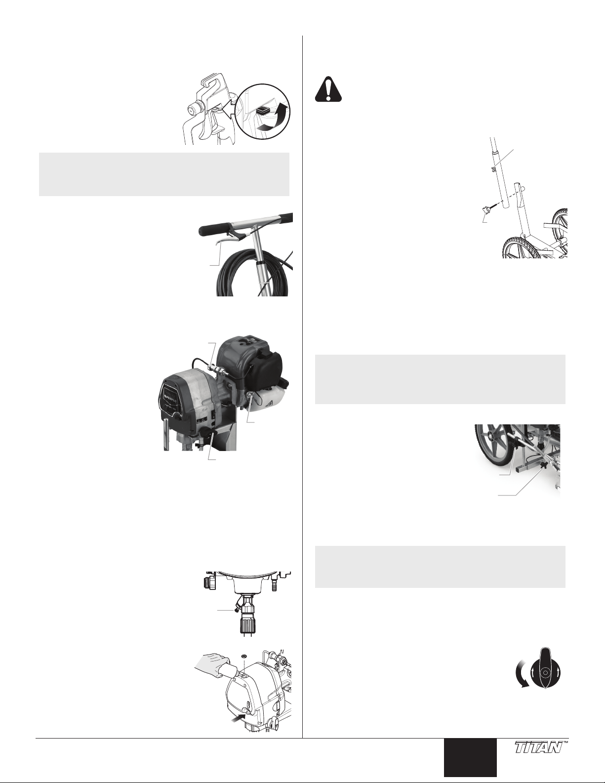
1. Attach the handle to the cart.
a. Line up the hole in the bottom
of the handle with the support
weldment on the cart.
b. Thread the bolt through the
hole in the handle and the
weldment. Tighten by turning
the knob of the bolt clockwise.
c. Position the handle at the
desired height. Loosen the
knob on the rear of the support
weldment in order to to loosen
the handle.
d. Pull the handle up or down to
the desired height. Tighten the
handle knob in order to secure the handle.
2. Make sure that the siphon tube and the return hose are
attached and secure.
3. Using a wrench, thread the airless spray hose to the outlet
tting on the sprayer. Tighten securely.
4. Attach an airless spray gun to the spray hose. Using two
wrenches (one on the gun and one on the hose), tighten
securely.
NOTE: The spray gun and cables are mounted to the gun
support bar at the factory.
NOTE: Do not attach the tip to the spray gun yet.
Remove the tip if it is already attached.
5. Position the spray gun.
a. Loosen the support bar
knob and slide the gun
support bar to the desired
horizontal position. Make
sure the gun is far enough
away from the cart so that
the rear wheel does not
track over the fresh spray
pattern.
b. Loosen the gun riser
clamp and slide the spray
gun to the desired vertical position. A distance of 6”
from the tip to the spray surface is a good starting point.
NOTE: The height of the spray gun affects the width
of the spray pattern (i.e., the lower the gun, the
smaller the line width). Tip size also affects line
width.
6. Make sure the gun cable is operating properly. When
pulling the spray lever on the cart handle, the gun cable
should be pulling the trigger. This cable is factory-set to
operate properly. If adjustment to the gun trigger tension
is required, refer to the “Adjusting the Trigger Tension”
procedure in the Maintenance section of this manual.
7. Turn the PRIME/SPRAY knob to the
PRIME position.
IMPORTANT: Never operate unit for more
than ten seconds without fluid. Operating
this unit without fluid will cause unnecessary
wear to the packings.
© Titan Tool Inc. All rights reserved. 5
English
Page 6
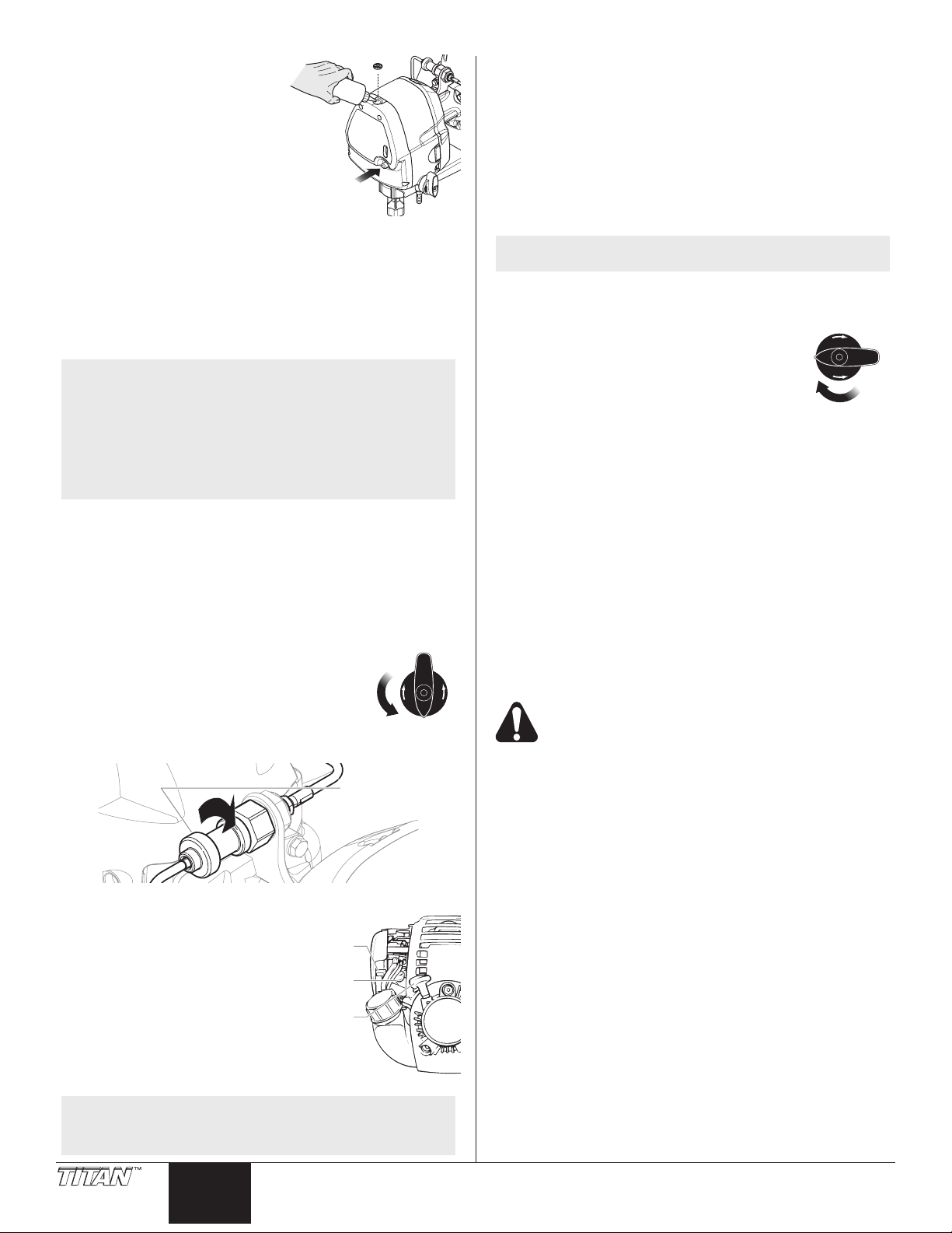
8. Remove AutoOiler cap with
SPRAY
PRIME
Clockwise
Prime
bulb
Starter
rope
Choke
lever
SPRAY
PRIME
a at blade screwdriver.
Squirt Piston Lube™ into the
AutoOiler. Replace cap.
9. Push AutoOiler button 2-5
times to lubricate the uid
section.
10. Check the engine oil level.
The gasoline engine oil
level is determined by the
manufacturer. Refer to the
engine manufacturer’s service
manual (supplied).
11. Fill the gas tank on the engine with unleaded gasoline
only. Do not mix the gasoline with 2-cycle oil.
Preparing to Paint
Before painting, it is important to make sure that the uid in the
system is compatible with the paint that is going to be used.
NOTE: Ifthisunitisnew,itisshippedwithtestuid
intheuidsectiontopreventcorrosionduring
shipmentandstorage.Thisuidmustbe
thoroughly cleaned out of the system before you
begin spraying.
Incompatibleuidsandpaintmaycausethe
valves to become stuck closed, which would
require disassembly and cleaning of the
sprayer’suidsection.
IMPORTANT: Always keep the trigger lock on the spray
gun in the locked position while preparing the system. If
necessary, loosen the gun holder clamp knob and then
engage the spray gun trigger lock.
1. Place the siphon tube into a container of the appropriate
solvent for the material being sprayed (refer to
recommendations of the material manufacturer). An
example of the appropriate solvent is water for latex paint.
2. Place the return hose into a metal waste container.
3. Turn the PRIME/SPRAY knob to the
PRIME position.
4. Fully depress the pusher stem to make
sure the inlet ball is free.
5. Turn the DirectLink pressure control knob
fully clockwise to minimum.
7. Slowly turn the DirectLink pressure control knob
counterclockwise to increase the pressure until uid starts
to come out of the return hose. Use only enough pressure
to keep the uid coming out.
8. Allow the sprayer to run for 15–30 seconds to ush the
test uid out through the return hose and into the waste
container.
9. Turn the DirectLink pressure control knob fully clockwise
to minimum.
10. Turn off the sprayer by pressing and holding the engine
shutoff switch until the motor shuts off.
NOTE: Make sure that the spray gun does not have a tip
or tip guard installed.
11. Place a metal waste container underneath the spray gun
to catch the solvent.
12. Start the engine.
13. Turn the PRIME/SPRAY knob to the
SPRAY position.
14. Turn the DirectLink pressure control knob
slowly counterclockwise to increase the
pressure.
15. Unlock the gun by turning the gun trigger
lock to the unlocked position.
16. Fully pull the spray lever on the cart handle. Fluid will
begin owing through the spray hose and out of the gun.
17. Continue to pull the spray lever on the cart handle until the
old solvent/test uid is gone and fresh solvent is coming
out of the gun.
18. Release the spray lever.
19. Lock the gun by turning the gun trigger lock to the locked
position. If necessary, loosen the gun holder clamp knob
and then engage the spray gun trigger lock. Move the
spray gun to its original position and tighten the clamp
knob.
20. Check the entire system for leaks. If leaks occur, turn the
sprayer off and follow the “Pressure Relief Procedure” in
this manual before tightening any ttings or hoses.
21. Follow the “Pressure Relief Procedure” in this manual
before changing from solvent to paint.
Be sure to follow the Pressure Relief Procedure
when shutting the unit down for any purpose,
including servicing or adjusting any part of the
spray system, changing or cleaning spray tips, or
preparing for cleanup.
6. Start the engine:
a. Move the choke lever up to
the full choke position.
b. Push the rubber prime button
7-10 times.
c. Pull the starter rope rapidly
and rmly. Continue to hold
the rope as you let it return.
Pull and return the rope until
the engine starts.
d. Once the engine is running,
slowly move the choke lever
down to the closed position.
NOTE: If you are having trouble starting the motor,
6 © Titan Tool Inc. All rights reserved.
rotate the DirectLink pressure control knob 1-2
turns counter-clockwise.
English
Page 7
Painting
SPRAY
PRIME
Clockwise
Prime
bulb
Starter
rope
Choke
lever
SPRAY
PRIME
Tip seal
retainer
Tip seal
Tip
Tip
handle
Tip
guard
1. Place a ve gallon bucket of material between the bucket
holders on the cart. Make sure the bucket holders hold
the ve gallon bucket securely. Adjust the bucket holders
using the thumb screw located underneath each holder, if
necessary.
NOTE: Whenusingthislinestriperforrsttime,itmay
2. Place the siphon tube into the bucket of material.
3. Place the return hose into a metal waste container.
4. Turn the PRIME/SPRAY knob to the
5. Fully depress the pusher stem to make
6. Turn the DirectLink pressure control knob
7. Start the engine:
a. Move the choke lever up to
b. Push the rubber prime button
c. Pull the starter rope rapidly
d. Once the engine is running,
8. Slowly turn the DirectLink pressure control knob
9. Allow the sprayer to run for 15–30 seconds to ush the
10. Turn the DirectLink pressure control knob fully clockwise
11. Turn off the sprayer by pressing and holding the engine
12. Remove the return hose from the waste container and
13. Start the engine.
14. Turn the PRIME/SPRAY knob to the
15. Unlock the gun by turning the gun trigger
16. Turn the DirectLink pressure control knob
17. Fully pull the spray lever on the cart handle. Fluid will
18. Continue to pull the spray lever on the cart handle until
19. Release the spray lever.
© Titan Tool Inc. All rights reserved. 7
be helpful to use water in place of paint to gain
familiarity with the operation of the line striper.
After changing from water to paint, test spray
severallinesoncardboard,roongfelt,orrosin
paper before striping to ensure correct line width.
PRIME position.
sure the inlet ball is free.
fully clockwise to minimum.
the full choke position.
7-10 times.
and rmly. Continue to hold
the rope as you let it return.
Pull and return the rope until
the engine starts.
slowly move the choke lever
down to the closed position.
counterclockwise to increase the pressure until uid starts
to come out of the return hose. Use only enough pressure
to keep the uid coming out.
test uid out through the return hose and into the waste
container.
to minimum.
shutoff switch until the motor shuts off.
place it in its operating position above the bucket of
material.
SPRAY position.
lock to the unlocked position.
slowly counterclockwise to increase the
pressure.
begin owing through the spray hose and out of the gun.
material is coming out of the gun.
20. Lock the gun by turning the gun trigger lock to the locked
position. If necessary, loosen the gun holder clamp knob
and then engage the spray gun trigger lock. Move the
spray gun to its original position and tighten the clamp
knob.
21. Turn the DirectLink pressure control knob fully clockwise
to minimum.
22. Turn the PRIME/SPRAY knob to PRIME.
23. Turn off the sprayer by pressing and holding the engine
shutoff switch until the motor shuts off.
24. Attach tip guard and tip to the spray gun. Refer to the
instructions later in this section.
POSSIBLE INJECTION HAZARD. Do not spray
without the tip guard in place. Never trigger the
gun unless the tip is in either the spray or the
unclog position. Always engage the gun trigger
lock before removing, replacing or cleaning tip.
25. Start the engine.
26. Turn the PRIME/SPRAY knob to SPRAY.
27. Fully pull the spray lever on the cart handle to trigger the
spray gun. Test the spray pattern and line position on a
long piece of roong felt or cardboard. Check for proper
line width and position. If adjustment to the position of
the spray gun is required, refer to the “Setup” procedure
earlier in this section.
28. Make sure that the spray gun shuts off completely when
the gun trigger is released. If adjustment to the trigger
tension is required, refer to the “Adjusting the Trigger
Tension” procedure in the Maintenance section of this
manual.
29. Begin striping.
a. Position the line striper slightly in front of the striping
path.
b. Start walking with the line striper and trigger the gun at
the beginning of the striping path.
c. At the end of striping path, release the trigger and
continue walking a short distance, if possible.
NOTE: Triggering the gun after the line striper is moving
and releasing the trigger before the line striper
stops produces an evenly painted line from start
tonish.Ifthestripingpathendsatanobstacle,
release the trigger at the same moment that the
line striper stops moving.
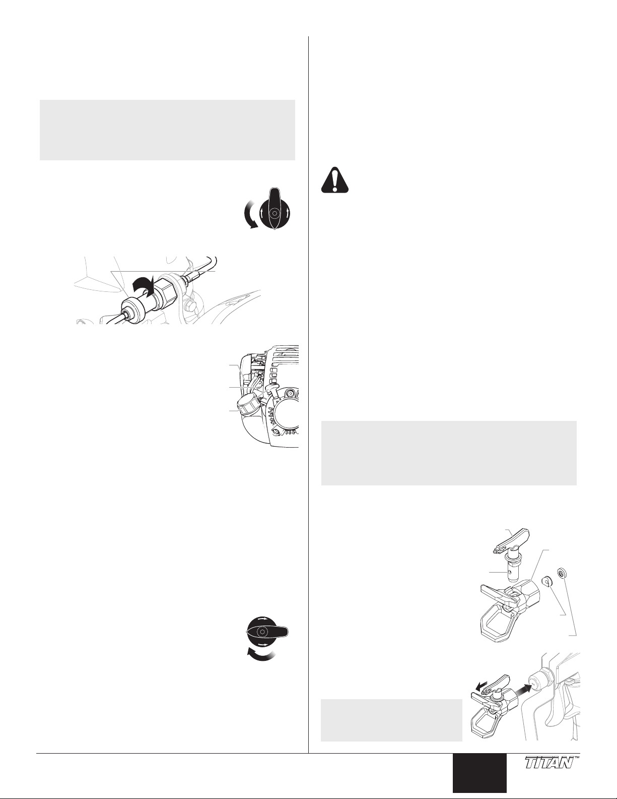
Attaching the Tip Guard and Tip
Use the following procedure to
install the tip guard and tip to the
spray gun.
1. Perform the “Pressure Relief
Procedure” described in this
manual.
2. Using the arrow head on the
tip handle, insert the tip seal
and tip seal retainer into the
back of the tip guard. Press
in for nal adjustment.
3. Insert the tip into the slot on
the tip guard.
4. Thread the tip guard onto the
gun. Position the tip guard in
the desired spraying position
and tighten securely.
NOTE: The arrow on the tip
handle should be
pointing in the forward
direction for spraying.
English
Page 8

Pressure Relief Procedure
SPRAY
PRIME
Tip
Guard
Tip
Tip Seal
Retainer
Tip Seal
Be sure to follow the pressure relief procedure
when shutting the unit down for any purpose,
including servicing or adjusting any part of the
spray system, changing or cleaning spray tips, or
preparing for cleanup.
1. Lock the gun by turning the gun trigger lock to the locked
position. If necessary, loosen the gun holder clamp knob
and then engage the spray gun trigger lock. Move the
spray gun to its original position and tighten the clamp
knob.
2. Turn the DirectLink pressure control knob fully clockwise
to minimum.
3. Turn the PRIME/SPRAY knob to the
PRIME position.
4. Turn off the sprayer by pressing and
holding the engine shutoff switch until the
motor shuts off.
5. Unlock the gun by turning the gun trigger lock to the
unlocked position.
6. Fully pull the spray lever on the cart handle to trigger the
spray gun and release any remaining pressure in the
hose.
7. Lock the gun by turning the gun trigger lock to the locked
position. If necessary, loosen the gun holder clamp knob
and then engage the spray gun trigger lock. Move the
spray gun to its original position and tighten the clamp
knob.
Clearing a Clogged Tip
If the spray pattern becomes distorted or stops completely while
the trigger is pulled, follow these steps.
1. Place a sheet of cardboard or small
bucket under the spray gun to catch
the paint.
2. Rotate the tip 180º so that the
arrow on the tip handle is pointing
opposite the spray direction.
Changing a Spray Tip
Tips can be removed and replaced easily without disassembling
the gun.
Never attempt to change or clean the tip or tip
guard without first performing the “Pressure Relief
Procedure.”
1. Perform the “Pressure Relief Procedure” described in the
sprayer’s Owner’s Manual.
2. Remove the tip from the slot on the tip guard.
3. Insert the new tip into the slot on the tip guard. The
arrow on the tip handle should be pointing in the forward
direction for spraying.
Removing the Seal and Tip Seal
1. Remove the tip from the tip
guard.
2. Insert the tip handle through
the front of the tip guard.
3. Push the seal and tip seal out
through the back of the tip
guard.
Identifying Tip Sizes
To identify tip sizes, use the following formula. A “1908” tip size
will be used in this example.
The last two digits divided by two represent the size of the spray
pattern when spraying 6” away from the work surface:
08 ÷ 2 = 4” spray pattern
The rst two digits represent the diameter of the orice on the tip:
19 = .019” orice
NOTE: Worn spray tips will adversely affect the spray
pattern and result in reduced production, poor
nish,andwastedmaterial.Replaceworntips
immediately.
NOTE: Ifthetipisdifculttorotate,relievepressure
by 1) slowly turning the PRIME/SPRAY knob to
PRIME, 2) unlock the spray gun, and 3) squeeze
the spray lever. Release the lever, lock the spray
gun, and try rotating the spray tip again.
3. Make sure the PRIME/SPRAY knob is turned to SPRAY.
Unlock the spray gun.
4. Trigger the gun once so that the pressure can blow the
clog out.
IMPORTANT: Never pull the trigger more than once at time
with the tip in the reverse position.
5. Continue this procedure until the tip is clear of the clog.
Do not attempt to clean the tip with your finger.
Do not use a needle or other sharp pointed
instrument to clean the tip. The hard tungsten
carbide is brittle and can be chipped.
Stenciling
To stencil with this line striper, make multiple spraying passes
from right to left over the stencil with the spray gun connected
to the gun holder. Or, the spray gun can be removed and used
independently from the striper.
To remove the spray gun:
1. Perform the Pressure Relief Procedure in the Operation
section of this manual.
2. Loosen the gun holder block knob on top of the gun
holder.
3. Slide the spray gun out of the gun holder.
Operating the Front Caster
The front caster on the cart is designed to track the sprayer in
either a straight line or allow free-wheel striping. To adjust the
front caster:
1. Pull the handle on the side
of the caster up and back to
release the wheel for freewheel striping.
2. To lock the wheel back into
place, pull the handle down.
Once the front wheel is turned
straight again, the wheel will
lock back into place.
8 © Titan Tool Inc. All rights reserved.
English
Page 9
Cleanup
SPRAY
PRIME
SPRAY
PRIME
Seals
Garden
hose
Pump
cleaning
adapter
Siphon
tube
Special cleanup instructions for use with
flammable solvents:
• Always ush spray gun preferably outside and at least one
hose length from spray pump.
• If collecting ushed solvents in a one gallon metal
container, place it into an empty ve gallon container, then
ush solvents.
• Area must be free of ammable vapors.
• Follow all cleanup instructions.
IMPORTANT: The sprayer, hose, and gun should be cleaned
thoroughly after daily use. Failure to do so permits material
to build up, seriously affecting the performance of the unit.
Always spray at minimum pressure with the gun
spray tip removed when using mineral spirits or
any other solvent to clean the sprayer, hose, or
gun. Static electricity buildup may result in a fire
orexplosioninthepresenceofflammablevapors.
1. Follow the “Pressure Relief Procedure” found in the
Operation section of this manual.
2. Remove the gun tip and tip guard and clean with a brush
using the appropriate solvent.
3. Place the siphon tube into a container of the appropriate
solvent (refer to recommendations of the material
manufacturer). An example of the appropriate solvent is
water for latex paint.
4. Place the return hose into a metal waste container.
5. Turn the PRIME/SPRAY knob to the
PRIME position.
6. Start the engine.
7. Slowly turn the DirectLink pressure control
knob counterclockwise to increase the
pressure until uid starts to come out of the return hose.
Use only enough pressure to keep the uid coming out.
8. Allow the uid to circulate through the sprayer and ush
the paint out of the return hose into the metal waste
container.
9. Turn off the sprayer by pressing and holding the engine
shutoff switch until the motor shuts off.
10. Place a metal waste container underneath the spray gun
to catch the paint and solvent.
11. Start the engine.
12. Turn the PRIME/SPRAY knob to the
SPRAY position.
13. Turn the DirectLink pressure control knob
slowly counterclockwise to increase the
pressure.
14. Fully pull the spray lever on the cart
handle to trigger the spray gun. Fluid will begin owing
through the spray hose and out of the gun.
15. Continue to pull the spray lever on the cart handle until the
material is ushed out of the hose and the solvent coming
out of the gun is clean.
16. Release the spray lever.
Special Cleanup
IMPORTANT: Perform the following procedure after
spraying with water-based materials only.
Perform the following procedure when the valves of the sprayer
are stuck or when preparing the sprayer for long term storage.
The use of a pump cleaning adapter that attaches to the bottom
of the siphon tube is required (the pump cleaning adapter is
included with the sprayer).
1. Lock the gun and remove the spray tip assembly. If
necessary, loosen the gun holder clamp knob and then
engage the spray gun trigger lock. Move the spray gun
to its original position and tighten the clamp knob. Place
the suction tube and return tube into an empty waste
container.
2. Using a garden hose, rinse off the siphon tube, return
hose and inlet lter. Empty the waste container.
3. Remove the inlet lter
from the suction tube
and place into a waste
container.
4. Verify that the seals
are present inside the
adapter and suction
tube. Thread the pump
cleaning adapter onto a
garden hose. Connect
the hose and adapter to
the tting on the end of
the siphon tube.
5. Unclip the return hose
from the siphon tube and
place it into the waste
container.
6. Turn the PRIME/SPRAY knob to the PRIME position.
7. Turn on the water supply.
8. Start the engine. Water will go into the siphon tube and
out through the return hose. Let the sprayer run for a few
minutes to allow the return hose to be ushed.
9. Turn off the sprayer by pressing and holding the engine
shutoff switch until the motor shuts off.
10. Place a metal waste container underneath the spray gun
to catch the cleaning solution.
11. Start the engine.
12. Turn the PRIME/SPRAY knob to the SPRAY position.
13. Turn the DirectLink pressure control knob slowly
counterclockwise to increase the pressure.
14. Fully pull the spray lever on the cart handle to trigger the
spray gun. Fluid will begin owing through the spray hose
and out of the gun.
15. Continue to pull the spray lever on the cart handle until the
material is ushed out of the hose and the water coming
out of the gun is clean.
16. Release the spray lever.
17. Follow the “Pressure Relief Procedure” found in the
Operation section of this manual.
NOTE: For long-term or cold weather storage, pump
Pump Saver™ through the entire system.
17. Follow the “Pressure Relief Procedure” found in the
Operation section of this manual.
18. Store the sprayer in a clean, dry area.
IMPORTANT: Do not store the sprayer under pressure.
© Titan Tool Inc. All rights reserved. 9
English
Page 10
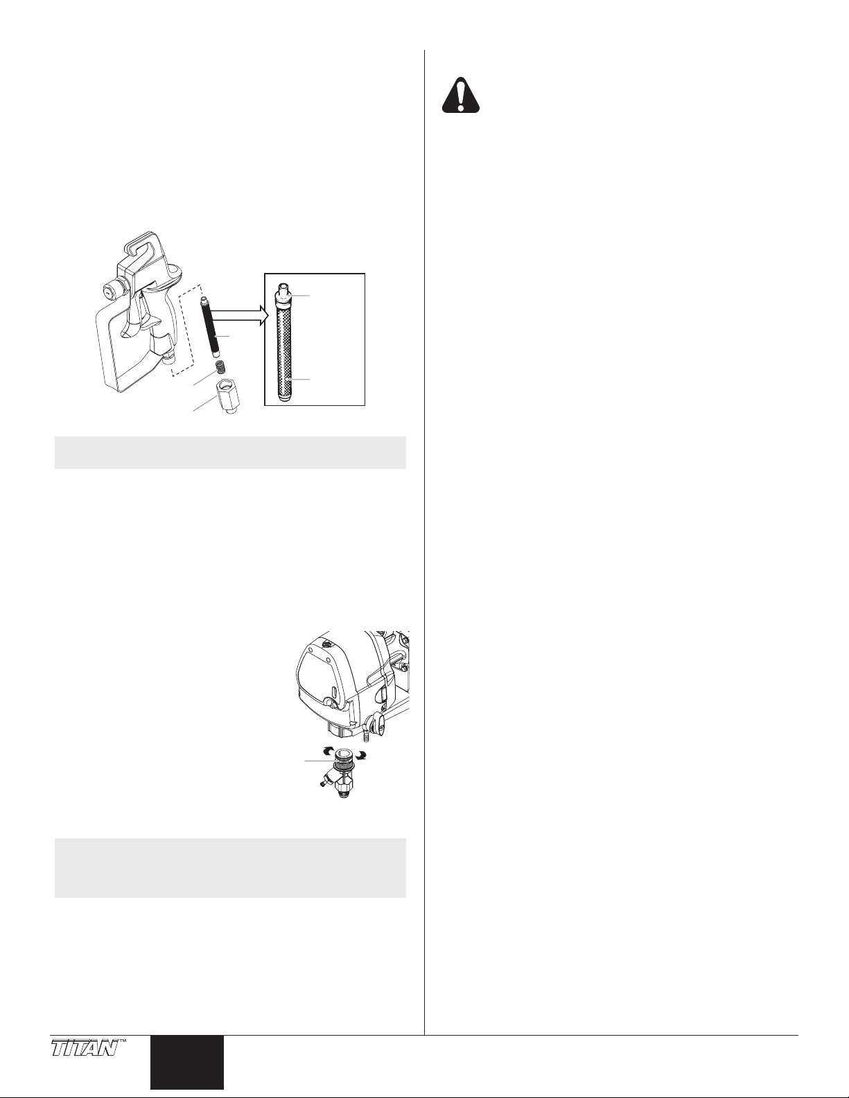
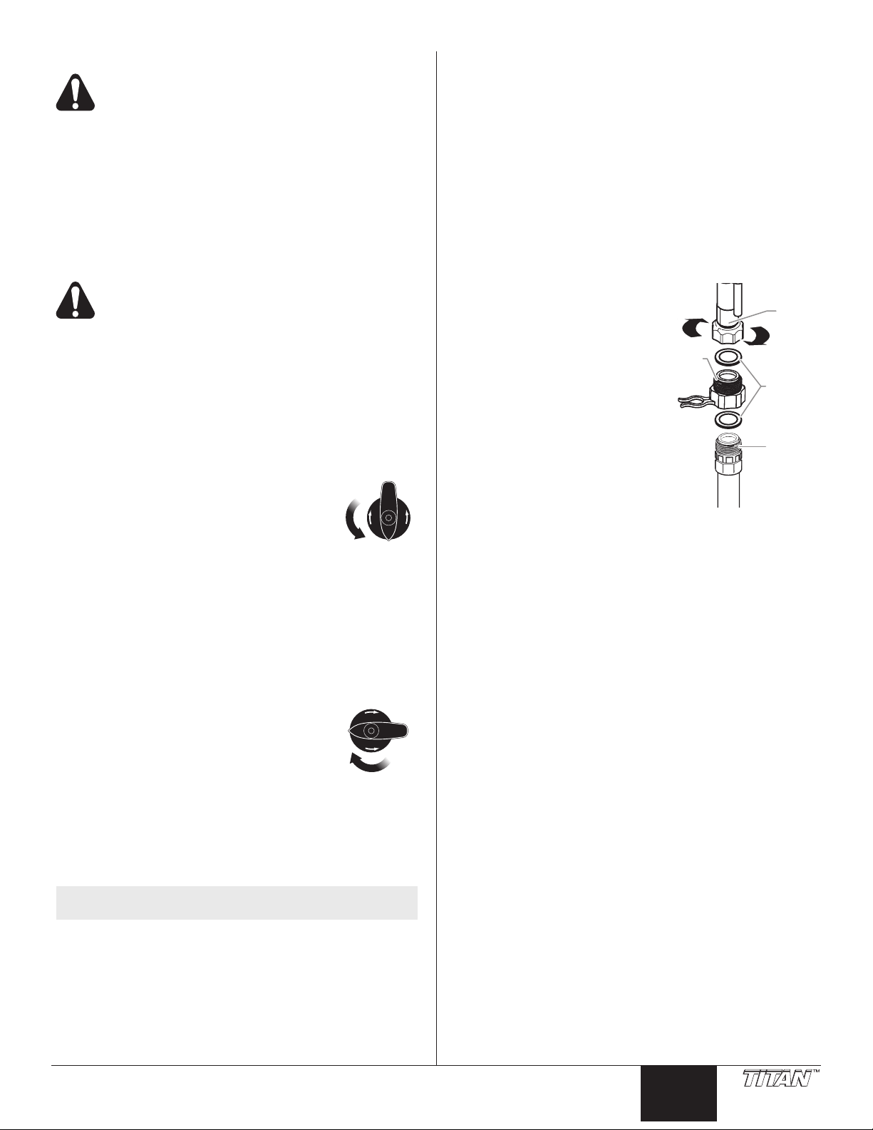
Cleaning/Replacing the Gun Filter
Filter
Spring
Fitting
Tapered
end
(filter top)
Hole
Sureflo
valve
The gun lter must be cleaned after every use of the sprayer.
When using thicker spray materials, the lter might need to be
cleaned more often.
1. Perform Pressure Relief Procedure in the Operation
section of this manual.
2. Unscrew the tting from the bottom of the spray gun using
an adjustable wrench, making sure not to lose the spring.
3. Remove the lter from the spray gun housing and clean
with the appropriate cleaning solution (warm, soapy water
for latex paints, mineral spirits for oil-based materials).
4. Inspect the lter for holes. Replace if holes are found.
NOTE: Neverpokethelterwithasharpinstrument!
5. Replace the cleaned lter, tapered end rst, into the gun
housing. The tapered end of the lter must be loaded
properly into the gun. Improper assembly will result in a
plugged tip or no ow from the gun.
6. Reassemble the spray gun.
CleaningtheSureo™ValveAssembly
Cleaning or servicing the Sureo Valve may be required if the
unit has priming problems.
1. Remove the siphon tube.
2. Unscrew the inlet valve
assembly from the sprayer.
Visually inspect the inside and
outside of the Sureo Valve
assembly. Clean any paint
residue with the appropriate
cleaning solution.
3. Lubricate the o-ring on the
Sureo Valve with petroleum
jelly. Replace Sureo valve
assembly by threading it into
the sprayer. Torque to 32–38
ft./lbs.
4. Replace the siphon tube and
tighten securely.
Maintenance
Before proceeding, follow the Pressure Relief
Procedure outlined previously in this manual.
Additionally, follow all other warnings to reduce
the risk of an injection injury, injury from moving
parts, or electric shock.
General Repair and Service Notes
The following tools are needed when repairing this sprayer:
at-blade screwdriver T20 Torx head driver
needle-nose pliers adjustable wrench
1. Before repairing any part of the sprayer, read the
instructions carefully, including all warnings.
IMPORTANT: Never pull on a wire to disconnect it. Pulling
on a wire could loosen the connector from the wire.
2. Test your repair before regular operation of the sprayer
to be sure that the problem is corrected. If the sprayer
does not operate properly, review the repair procedure to
determine if everything was done correctly. Refer to the
Troubleshooting section to help identify other possible
problems.
3. Make certain that the service area is well ventilated in
case solvents are used during cleaning. Always wear
protective eyewear while servicing. Additional protective
equipment may be required depending on the type of
cleaning solvent. Always contact the supplier of solvents
for recommendations.
4. If you have any further questions concerning your TITAN
Airless Sprayer, call TITAN:
Technical Service (U.S.) .......................1-800-526-5362
Fax ................................................1-800-528-4826
Adjusting the Trigger Tension
Use the following procedure to adjust the spring tension of the
trigger lever on the gun holder assembly. The trigger lever pulls
and releases the spray gun trigger when operated from the spray
lever on the cart. The proper tension ensures that the gun will
shut off when the gun trigger is released. To ensure proper
tension, there should be approximately a 1/16” gap between the
trigger lever and the spray gun trigger.
IMPORTANT: Always keep the trigger lock on the spray
gun in the locked position while making adjustments to the
system. If necessary, loosen the gun holder clamp knob and
then engage the spray gun trigger lock. Move the spray gun
to its original position and tighten the clamp knob.
NOTE: If priming problems continue, you may need to
10 © Titan Tool Inc. All rights reserved.
replacetheSureovalve.ContactTechnical
ServicetoorderanewSureoValveassembly.
English
Page 11
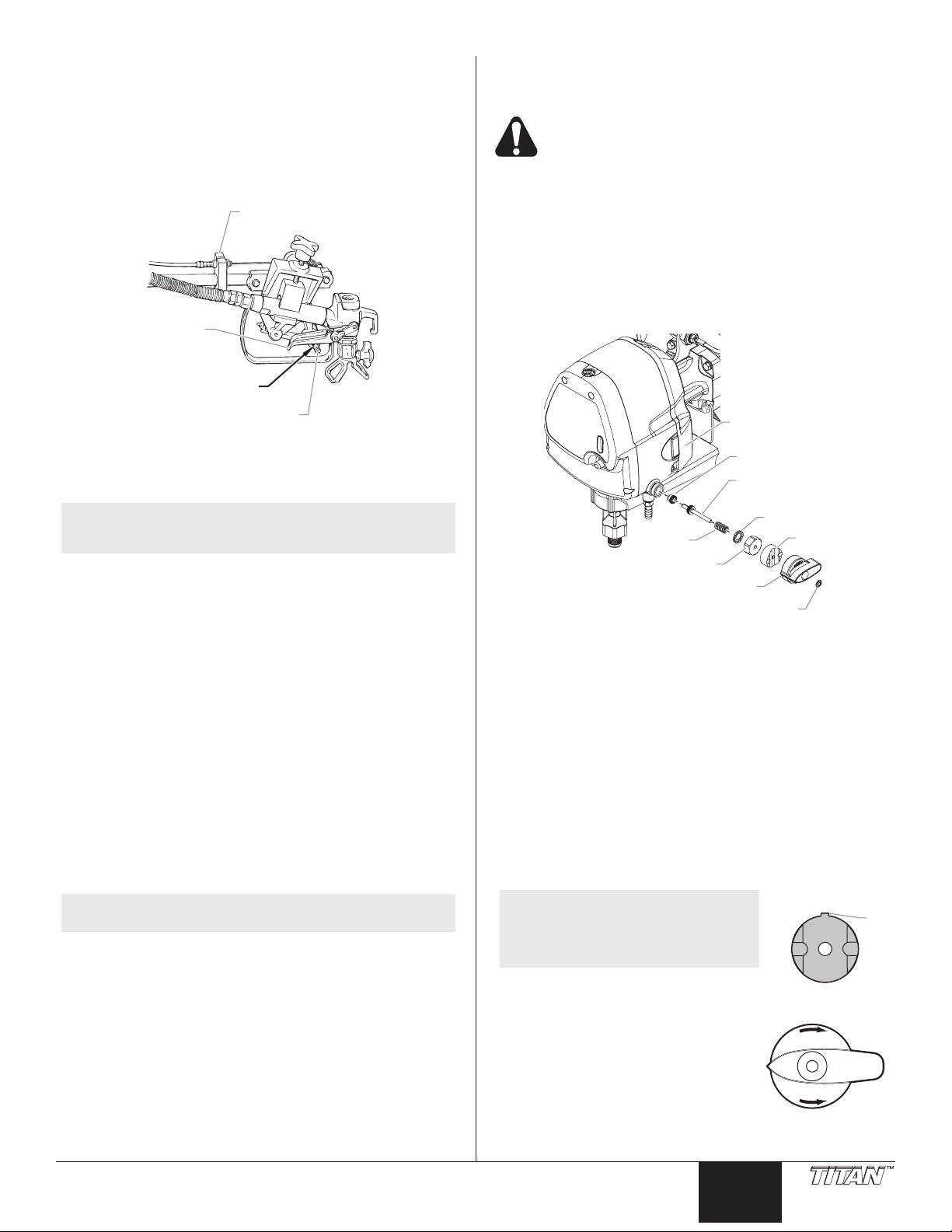
1. Using a 9/16” hex wrench, loosen the hex screw on the
Spray gun
trigger
Trigger lever
1/16" gap
Cable block
(hex screw on back)
Pump head
Star washer
Stem/ball
assembly
Seat
Cam
Spring
Hex nut
Retaining clip
Valve knob
Ta b
Tab on cam in
12:00 position
SPRAY
PRIME
Pointer on valve knob
in 9:00 position
cable block.
2. Move the cable block in the appropriate direction to create
a gap of 1/16” between the trigger lever and spray gun
trigger.
a. Slide the cable block toward the gun to increase the gap
between the trigger lever and spray gun trigger.
b. Slide the cable block away from the gun to decrease the
gap between the trigger lever and spray gun trigger.
3. Tighten the hex screw securely.
Maintaining the Engine
Replacing the PRIME/SPRAY Valve
Perform the following procedure using PRIME/SPRAY valve
replacement kit P/N 759-380.
Before proceeding, follow the Pressure Relief
Procedure outlined previously in this manual.
Additionally, follow all other warnings to reduce the
risk of an injection injury, injury from moving parts,
or electric shock.
1. Pry off the retaining clip from inside the recessed portion
of the valve knob. Remove the valve knob.
2. Slide the cam off of the stem/ball assembly.
3. Using a wrench, remove the hex nut from the pump head.
4. Remove the star washer, spring, and stem/ball assembly
from the pump head.
5. Using a 7/32” hex wrench, remove the stem/ball assembly
seat from the pump head.
NOTE: Fordetailedenginespecicationsand
maintenance, refer to the separate engine manual
supplied with this sprayer.
Routine Engine Maintenance
Daily
• Check and ll the gas tank.
• After the rst 20 hours of operation, drain the oil and
rell with clean oil. Check the engine oil level and ll as
necessary.
Weekly
• Remove the cover of the air lter and clean the element.
Replace the element if necessary. If operating in an
unusually dusty environment, check the lter daily and
replace if necessary. (Replacement elements can be
purchased from your local Titan dealer.)
• After each 50 hours of operation: Change the engine oil.
Safety Shut-Off Switch
The safety shut-off switch is pre-set by the factory to shut down
the sprayer to prevent over-pressurization. Do not attempt to
adjust or tamper with the safety shut-off switch. Contact an
authorized service center if this setting requires adjustment.
NOTE: The safety shut-off switch should be set to shut
down the sprayer between 3200 – 3300 PSI.
6. Tighten the new stem/ball assembly seat into the pump
head. Use a 7/32” hex wrench. Torque to 6-8 ft./lbs.
7. Apply a light coating of hydraulic oil around the o-ring on
the new stem/ball assembly.
8. Push the stem/ball assembly into the stem/ball assembly
seat in the pump head.
9. Place the new spring and star washer around the stem/
ball assembly.
10. Slide the new hex nut onto the stem of the stem/ball
assembly, thread it onto the pump head, and tighten with a
wrench. Torque the nut to 12-14 ft./lbs.
11. Apply a light coating of grease to the top of the cam.
12. Slide the new cam onto the stem of the stem/ball
assembly and over the hex nut. The design of the cam
will allow the hex nut to t inside the cam, causing the cam
to lock in position.
NOTE: Positionthecamonthehex
nut so that the tab on the
side of the cam is as close
to the 12:00 position as
possible.
© Titan Tool Inc. All rights reserved. 11
13. Place the new PRIME/SPRAY
valve knob over the cam with
the pointer on the knob as close
to the 9:00 position as possible.
Make sure the knob is pushed
completely onto to the cam (the
knob should cover the cam
completely).
English
Page 12
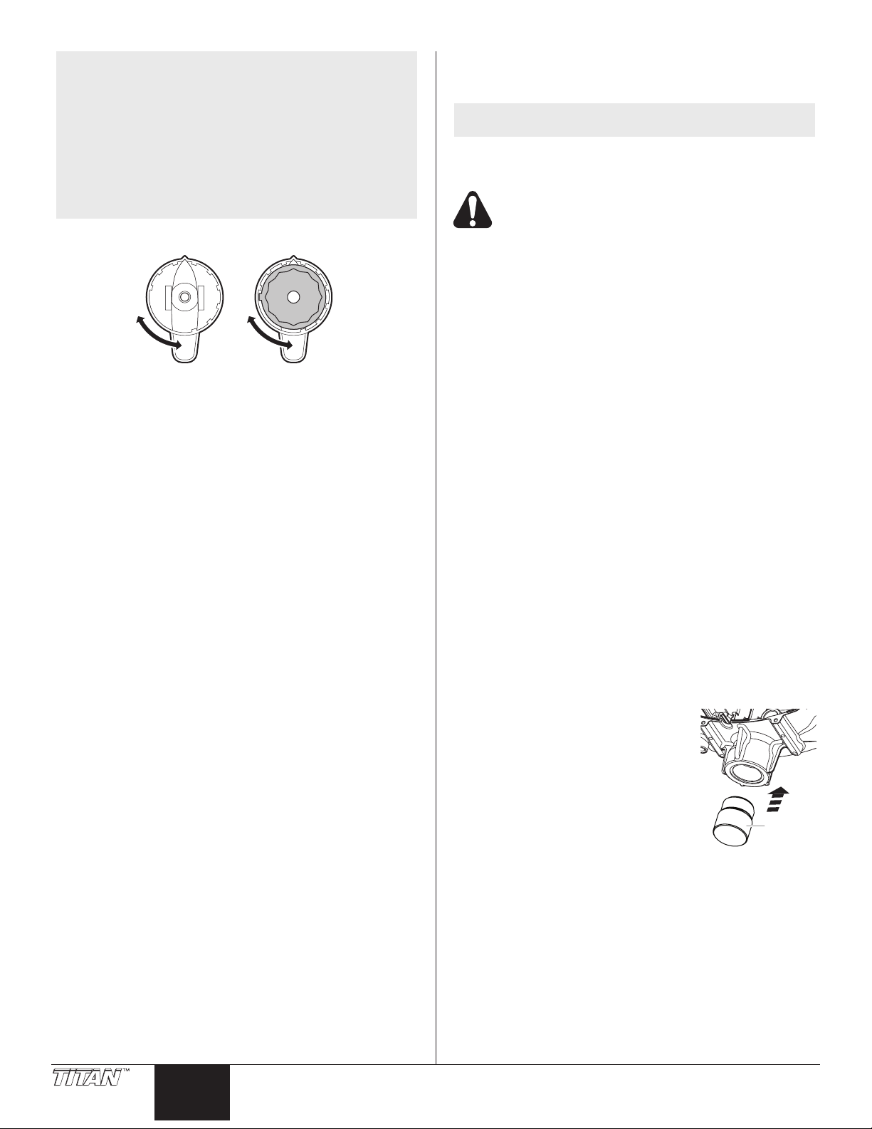
NOTE: The knob is designed to allow 90º of movement
Back of PRIME/SPRAY valve knob
90º Opening Cam positioned
with tab in
90º Opening
Insertion
Tool
between the SPRAY and PRIME positions. The
inside of the knob has a 90º opening in it’s
circumference where the tab of the cam should
be positioned to allow this movement. When
placing the knob with the arrow in the 9:00
position, make sure that the tab on the cam
is within the 90º opening on the inside of the
knob. Then, make sure the knob is at the end of
its movement in the clockwise direction (this is
the SPRAY position) before continuing with this
procedure.
14. Slowly turn the knob counterclockwise until the bottom of
the knob moves out to where it is ush with the bottom of
the cam (approximately 5–7º).
15. Place the retaining clip over the stem of the stem/ball
assembly where the stem passes through the recessed
portion of the knob.
16. Using a 5/16” (8mm) nut driver, push the clip into the
recessed portion of the knob with steady, even pressure
until it stops.
IMPORTANT: Do not hammer or wiggle the clip into
position. It will damage the clip.
18. Turn the PRIME/SPRAY knob to the PRIME position.
19. Start up the sprayer and run water through the system to
check for leaks. If there are no leaks, the sprayer is ready
to use.
Servicing the Fluid Section
Use the following procedures to replace the seals and repack the
uid section.
NOTE: Repacking kit P/N 759-365 is available. For best
results use all parts supplied in this kit.
Disassembling the Fluid Section
Before proceeding, follow the Pressure Relief
Procedure outlined previously in this manual.
Additionally, follow all other warnings to reduce the
risk of an injection injury, injury from moving parts
or electric shock.
1. Remove the suction set.
2. Remove the front cover and the four (4) screws that
secure it using a T20 Torx head driver.
3. Remove the yoke screw and washer that secures the
dowel pin. The dowel pin connects the yoke to the piston.
4. Using a pliers, pull the dowel pin out.
5. Rotate the pump shaft so the piston is in the top dead
center position. This can be done by pushing on the yoke.
This is required to disassemble all the parts.
6. Unscrew and remove the Sureo Valve assembly (refer to
the Cleaning the Sureo Valve procedure in the Cleanup
section of this manual).
7. Remove the piston assembly by pushing down on the
piston near the yoke.
8. Unscrew and remove the top nut using an adjustable
wrench.
9. Remove the worn seal using a at head screwdriver or
punch. Remove the top seal from the top by pressing
against the side of the seal and popping it out. Be sure
not to scratch the housing where the seals are located.
10. Clean the area where the new seals are to be installed.
Assembling the Fluid Section
1. Lubricate the new top seal with Piston Lube (P/N 314-480)
or light household oil and place the seal by hand with the
cup side of seal down into the top port of the housing.
2. Place a small amount of anti-seize on the threads of the
top nut. Place the top nut into the top of the housing and
tighten with an adjustable wrench. This will drive the top
seal into the correct position.
3. Lubricate the seal on the piston/
seal assembly similar to the
top seal. Place the piston/seal
assembly into the bottom of the
housing. Insert the insertion tool
and push into position to properly
seat the piston/seal. Remove
the insertion tool.
4. Install the new O-ring on the
Sureo Valve assembly, lubricate
with Piston Lube (P/N 314-480),
thread into the bottom (inlet) of the housing, and tighten
with an adjustable wrench. This will drive the bottom seal
into the correct position.
5. Align the piston with the yoke. Be careful not to damage
the piston.
6. Apply any type of non-silicone household grease to the
piston and yoke area (where the dowel is inserted) to
prolong life.
7. Install the dowel pin to connect the yoke to the piston.
The piston may have to be moved up or down to align with
the yoke.
8. Install the yoke screw and washer to secure the dowel pin.
12 © Titan Tool Inc. All rights reserved.
English
Page 13
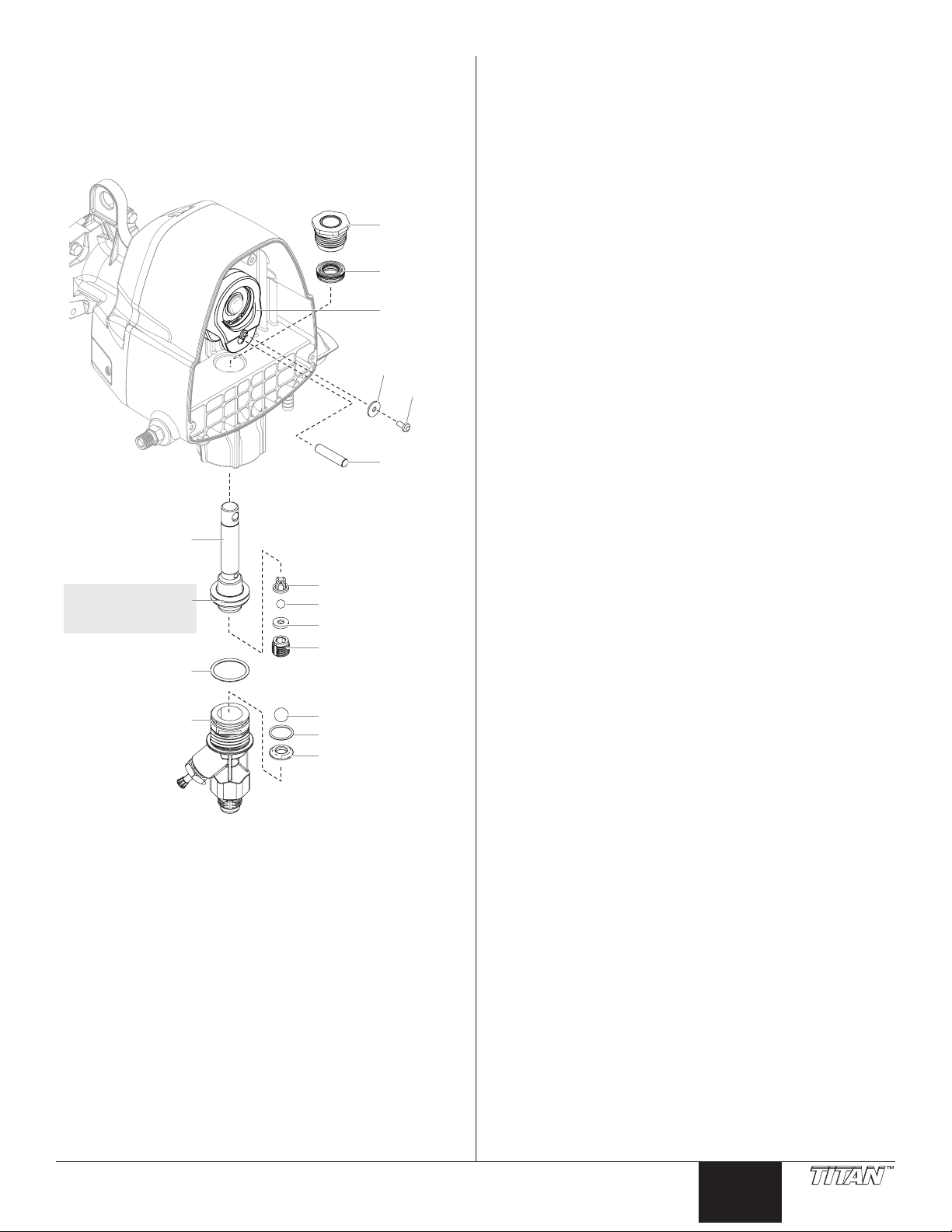
9. Turn pump right side up and apply a few drops of Piston
Top seal
(cup down)
Top nut
Dowel
Ball guide
Outlet ball
Outlet seat
Inlet ball
Inlet O-ring
Inlet seat
Outlet valve
Yoke
Piston/seal
assembly
O-ring
Sureflo
Valve
assembly
Washer
Screw
DO NOT attempt
to remove the seals
from the piston.
Lube or light household oil between the top nut and piston.
This will prolong the seal life.
10. Install front cover and four (4) screws.
11. Replace Sureo Valve and install the suction set.
12. Turn on the sprayer by following the procedure in the
“Operation” section of this manual and check for leaks.
© Titan Tool Inc. All rights reserved. 13
English
Page 14

Troubleshooting
Problem
A. The unit will not run.
B. The unit will not prime.
C. The unit will not build or
maintain pressure.
D. Fluid leakage at the upper end
of the uid section.
E. Excessive surge at the spray
gun.
F. Poor spray pattern.
G. The unit lacks power.
Cause
1. The pressure is set too low.
2. Faulty or loose wiring.
3. The gas tank is empty.
1. The PRIME/SPRAY knob is in the SPRAY
position.
2. Air leak in the siphon tube/siphon set.
3. The inlet screen is clogged.
4. The siphon tube/siphon set is clogged.
1. The spray tip is worn.
2. The spray tip is too large.
3. The gun lter, or inlet screen is clogged.
4. Material ows from the return hose when
the PRIME/SPRAY valve is in the SPRAY
position.
5. Air leak in the siphon tube/siphon set.
6. There is external uid leak.
7. There is an internal uid section leak
(seals are worn and/or dirty, valve balls are
worn).
8. Worn valve seats
1. The upper packings are worn.
2. The piston rod is worn.
1. Wrong type of airless spray hose.
2. The spray tip worn or too large.
3. Excessive pressure.
1. The spray tip is too large for the material
being used.
2. Incorrect pressure setting.
3. Insufcient uid delivery.
4. The material being sprayed is too viscous.
1. The pressure adjustment is too low.
Solution
1. Turn the DirectLink pressure control knob slowly
counterclockwise to increase the pressure.
2. Inspect or take to an authorized service center.
3. Fill the gas tank.
1. Rotate the PRIME/SPRAY knob to the PRIME
position.
2. Check the siphon tube/siphon set connection and
tighten or re-tape the connection with Teon tape.
3. Remove the inlet screen and clean.
4. Remove the siphon tube/siphon set and clean.
1. Replace the spray tip following the instructions in this
manual.
2. Replace the spray tip with a tip that has a smaller
orice following the instructions in this manual.
3. Remove the gun lter and clean. Remove the inlet
screen and clean.
4. Clean or replace the PRIME/SPRAY valve.
5. Check the siphon tube/siphon set connection and
tighten or re-tape the connection with Teon tape.
6. Check for external leaks at all connections. Tighten
connections, if necessary.
7. Clean the valves and service the uid section
following the “Servicing the Fluid Section” procedure
in the Maintenance section of this manual.
8. Reverse or replace the valve seats following the
“Servicing the Fluid Section” procedure in the
Maintenance section of this manual.
1. Repack the pump following the “Servicing the Fluid
Section” procedure in the Maintenance section of this
manual.
2. Replace the piston rod following the “Servicing the
Fluid Section” procedure in the Maintenance section
of this manual.
1. Replace hose with a minimum of 50’ of 1/4”
grounded textile braid airless paint spray hose.
2. Replace the spray tip following the instructions in this
manual.
3. Turn the DirectLink pressure control knob slowly
clockwise to decrease pressure.
1. Replace the spray tip with a new or smaller spray tip
following the instructions in this manual.
2. Adjust the DirectLink pressure control knob until the
desired spray pattern is acheived.
3. Clean all screens and lters.
4. Add solvent to the material according to the
manufacturer’s recommendations.
1. Take to an authorized service center.
14 © Titan Tool Inc. All rights reserved.
English
Page 15

Notes
© Titan Tool Inc. All rights reserved. 15
English
Page 16
Consignes de sécurite important · Lire toutes ces consignes avant
d’utiliser l’appareil. GARDER CES CONSIGNES.
Indique une situation à risque, laquelle, si elle n’est pas
évitée, peut entraîner des blessures graves, voire la mort.
a) Pourréduirelesrisquesd’incendieoud’explosion,dechoc
électrique et de blessure, vous devez lire et comprendre les
directivesgurantdanscemanuel.Familiarisez-vousavec
les commandes et l’utilisation adéquate de l’équipement.
b) AVERTISSEMENT – Pour réduire le risque
d’incendieoud’explosion:
1. Ne pulvérisez pas de matières inammables
ou combustibles près d’une amme nue, de voyants lumineux
ou de sources d’ignition telles que des objets chauds, cigarettes,
moteurs, matériel et appareils électriques. Évitez de produire
des étincelles en connectant et en déconnectant les cordons
électriques.
2. Pour les appareils destinés à n’utiliser que des produits à l’eau – Ne
pulvérisez pas et ne les nettoyez pas avec des liquides inammables.
Exclusivement pour usage avec liquides à base d’eau.
3. Pour les appareils destinés à un usage exclusif avec des produits
à l’eau ou des produits minéraux de type alcool avec un point
d’éclair minimum de 21 ºC (70 ºF) – Ne pulvérisez pas et ne les
nettoyez pas avec des liquides ayant un point d’éclair inférieur à
21 ºC (70 ºF). Le point d’éclair est la température à laquelle un
uide peut produire sufsamment de vapeur pour s’enammer.
4. L’écoulement de peinture ou de solvant dans l’équipement
peut produire de l’électricité statique. L’électricité statique crée
un risque d’incendie ou d’explosion en présence de fumées
de peinture ou de solvant. Toutes les pièces du système du
pulvérisateur, y compris la pompe, l’ensemble du tuyau, le
pistolet de pulvérisation et les objets dans et autour de la zone
de pulvérisation doivent être correctement reliés à la terre
pour protéger contre les décharges d’électricité statique et les
étincelles. N’utilisez que des tuyaux conducteurs ou reliés à la
terre pour pulvérisateurs de peinture sous vide à haute pression,
spéciés par le fabricant.
5. Vériez que tous les conteneurs ou systèmes de stockage sont
reliés à la terre pour éviter les décharges d’électricité statique.
6. Connectez à une prise électrique avec prise de terre et utilisez
des rallonges électriques reliées à la terre. N’utilisez pas
d’adaptateur 3 à 2.
7. N’utilisez pas de peinture ou de solvant contenant du halon,
par exemple, le chlore, les agents antimoisissure à l’eau de
Javel, le chlorure de méthylène et le trichloroéthane. Ils ne sont
pas compatibles avec l’aluminium. Contactez le fournisseur de
revêtements pour connaître la compatibilité du matériau avec
l’aluminium.
8. La zone de pulvérisation doit toujours être bien aérée. Une
bonne quantité d’air frais doit constamment traverser la zone
de pulvérisation pour éviter les accumulations de vapeurs
inammables. Le système de pompage doit être placé dans une
zone bien aérée. Ne pulvérisez pas le système de pompage.
9. Ne fumez pas dans la zone de pulvérisation.
10. N’actionnez pas d’interrupteurs électriques, de moteurs ou autres
dispositifs produisant des étincelles dans la zone de pulvérisation.
11. Maintenez la propreté de la zone et veillez à ce qu’elle ne
contienne pas de conteneurs de peinture ou de solvant, de
chiffons et autres matières inammables.
12. Sachez ce que contiennent la peinture et les solvants pulvérisés.
Lisez les ches de sécurité du matériel (MSDS) et les étiquettes
apposées sur les conteneurs de peintures et de solvants.
Respectez les consignes de sécurité du fabricant de peinture et
de solvant.
13. Placez la pompe à une distance minimum de 7,62 mètres (25
pieds) de l’objet à pulvériser, dans une zone bien aérée (ajoutez
de la longueur de tuyau si besoin est). Les vapeurs inammables
sont souvent plus lourdes que l’air. La zone près du sol doit être
très bien aérée. La pompe contient des pièces qui produisent des
arcs et émettent des étincelles pouvant enammer les vapeurs.
14. Le plastique peut causer des étincelles d’électricité statique.
N’accrochez aucun plastique dans une zone de pulvérisation
fermée. N’utilisez pas de toiles de protection en plastique quand
vous pulvérisez une matière inammable.
15. Ayez un extincteur en bon état de fonctionnement à portée de
main.
c) AVERTISSEMENT – Pour réduire le risque de
pénétration dans la peau :
1. Ne dirigez pas le pistolet sur et ne pulvérisez pas les
personnes ou les animaux.
2. N’approchez pas les mains ni d’autres parties du corps de la
sortie du produit. Par exemple, ne tentez pas d’arrêter une fuite
avec une partie du corps.
3. Utilisez toujours le protège-embout de la buse. Ne pulvérisez pas
sans que le protège-embout de la buse ne soit installé.
4. Utilisez exclusivement un buse de buse spécié par le fabricant.
5. Prenez garde quand vous nettoyez ou que vous changez les
embouts de buse. Si le buse se bouche pendant que vous
pulvérisez, verrouillez TOUJOURS la détente du pistolet, arrêtez
la pompe et libérez toute la pression avant de réparer ou de
nettoyer le buse ou le protecteur ou avant de changer d’buse. La
pression n’est pas libérée par l’arrêt du moteur. La poignée du
robinet-valve PRIME/SPRAY (AMORÇAGE/ PULVÉRISATION)
doit être placée sur PRIME pour libérer la pression. Consultez la
PROCÉDURE DE DÉCOMPRESSION décrite dans le manuel de
la pompe.
NOTE: Si nécessaire, desserrez le bouton de ensemble de
support à pistolet, puis engager le verrou de détente.
6. Ne laissez pas l’appareil sous tension ou sous pression quand
vous vous en éloignez. Quand vous n’utilisez pas l’appareil,
éteignez-le et libérez la pression conformément aux instructions
du fabricant.
7. La pulvérisation à haute pression peut injecter des toxines dans
le corps et causer de graves blessures corporelles. Si une telle
injection se produisait, consultez immédiatement un médecin.
8. Vériez les tuyaux et les pièces pour détecter des signes
d’endommagement : une fuite peut injecter le produit dans la
peau. Inspectez le tuyau avant chaque emploi. Changez tous les
tuyaux ou pièces endommagés.
9. Ce système peut produire une pression de 3000 PSI / 207 Bar.
N’utilisez que les pièces de rechange ou les accessoires spéciés
par le fabricant et ayant une pression nominale minimum de
3000 PSI. Ceci est valable pour les buses de pulvérisation, les
protecteurs de buse, les pistolets, les rallonges, les raccords et le
tuyau.
10. Verrouillez toujours la détente quand vous ne pulvérisez pas.
Vériez que le verrou de la détente fonctionne correctement.
Si nécessaire, desserrez le bouton de ensemble de support à
pistolet, puis engager le verrou de détente.
11. Vériez que toutes les connexions sont bien serrées avant
d’utiliser l’appareil.
12. Sachez comment arrêter l’appareil et le dépressuriser rapidement.
Soyez bien familiarisé avec les commandes. La pression n’est
pas libérée lorsque le moteur est arrêté. La poignée du robinet-
valve PRIME/SPRAY (AMORÇAGE/PULVÉRISATION) doit
être placée sur PRIME pour libérer la pression. Consultez la
PROCÉDURE DE DÉCOMPRESSION décrite dans le manuel de
la pompe.
13. Retirez toujours le buse de pulvérisation avant de rincer ou de
nettoyer le système.
REMARQUE À L’INTENTION DES MÉDECINS :
Les injections cutanées sont des lésions traumatiques; il importe
donc de les traiter sans délai. On NE DOIT PAS retarder ce
traitementsousprétextedevérierlatoxicitéduproduiten
cause, celle-ci n’étant conséquente que dans le cas d’injection
directe de certains produits dans le système sanguin. Il pourrait
s’avérer nécessaire de consulter un plasticien ou un spécialiste
en chirurgie reconstructive de la main.
16 © Titan Tool Inc. Tous droits réservés.
Français
Page 17
Consignes de sécurite important · Lire toutes ces consignes avant
d’utiliser l’appareil. GARDER CES CONSIGNES.
d) AVERTISSEMENT – Pour réduire le risque de blessure :
1. Portez toujours les gants, la protection oculaire, les vêtements
et un respirateur ou masque appropriés quand vous peignez.
Vapeurs dangereuses – Les peintures, solvants, insecticides
et autres matières peuvent être dangereux s’ils sont inhalés ou
entrent en contact avec le corps. Les vapeurs peuvent provoquer
d’importantes nausées, une perte de connaissance ou un
empoisonnement.
2. Munissez-vous d’une protection auditive. Le bruit émis par cet
appareil peut dépasser les 85 dB(A).
3. Ne travaillez pas et ne pulvérisez pas près d’enfants. Éloignez
toujours les enfants de l’équipement.
4. Ne travaillez pas avec les bras au-dessus de la tête ni sur un
support instable. Appuyez-vous bien sur les deux pieds pour
toujours conserver l’équilibre.
5. Soyez attentif et regardez ce que vous faites.
6. N’utilisez pas l’appareil quand vous êtes fatigué ou sous
l’inuence de drogues ou d’alcool.
7. Ne faites pas de nœuds avec le tuyau et ne le tordez pas trop. Le
tuyau à vide peut présenter des fuites suite à l’usure, les nœuds
ou les mauvais traitements. Une fuite risque d’injecter du produit
dans la peau.
8. N’exposez pas le tuyau à des températures ou des pressions
supérieures à celles spéciées par le fabricant.
9. N’utilisez pas le tuyau pour tirer ou soulever l’équipement.
10. Utilisez la plus basse pression possible pour rincer l’équipement.
11. Respectez tous les codes locaux, étatiques et nationaux
qui régulent la ventilation, la prévention d’incendies et le
fonctionnement.
12. Les normes de sécurité du gouvernement des États-Unis ont été
adoptées dans la loi Occupational safety and Health Act (OSHA).
Ces normes, en particulier la partie 1910 des Normes générales
et la partie 1926 des Normes de construction, doivent être
consultées.
13. Avant chaque emploi, vériez tous les tuyaux pour détecter
d’éventuelles coupures, fuites, abrasion ou couvercle bombé.
Vériez l’état ou le mouvement des accouplements. Changez
immédiatement le tuyau si l’une de ces conditions est vériée. Ne
réparez jamais un tuyau de peinture. Remplacez-le par un tuyau
conducteur à haute pression.
14. Ne pulvérisez pas à l’extérieur par temps venteux.
15. Débranchez toujours le cordon électrique de la prise avant de
travailler sur l’équipement (modèles de électrique seulement).
Sécurité des moteurs à essence
Les produits chimiques contenus dans les vapeurs
d’échappement de cet appareil sont reconnus par l’État de
la Californie (États-Unis) comme étant cancérigènes. Ils
peuvent également entraîner des anomalies congénitales ou
d’autres dangers pour la santé.
• Les moteurs sont conçus pour fonctionner en toute sécurité et
avec une abilité maximale s’ils sont utilisés conformément aux
instructions. Veuillez lire et comprendre le manuel de l’utilisateur
de Honda avant de faire fonctionner le moteur. Le non-respect
de ces consignes peut entraîner des dommages matériels ou des
blessures physiques graves.
• Pour éviter tout risque d’incendie et fournir une ventilation
adéquate, placez le moteur à une distance minimale de 1 mètre
(3 pieds) des immeubles et d’autres équipements pendant son
fonctionnement. Ne placez pas d’objets inammables à côté du
moteur.
• An de prévenir un incendie ou un risque d’explosion, évitez
de pulvériser ou d’éclabousser du solvant inammable près du
moteur.
• Tenez les enfants et les animaux domestiques à l’écart de la
zone de travail; vous éviterez ainsi tout risque de brûlures sur
les pièces chaudes du moteur et de blessures entraînées par les
accessoires utilisés par le moteur pour son fonctionnement.
• Sachez comment arrêter rapidement le moteur, et assurez-
vous que vous avez bien compris le fonctionnement de toutes
les commandes. Ne permettez jamais à une personne de faire
fonctionner le moteur sans connaître les instructions nécessaires.
© Titan Tool Inc. Tous droits réservés. 17
• L’essence est extrêmement inammable et explosive dans
certaines conditions.
• Remplissez le réservoir de carburant dans une zone bien
ventilée, moteur arrêté. Ne fumez pas et évitez toutes ammes
ou étincelles dans la zone de remplissage de carburant ou dans
une zone de stockage du carburant.
• Veillez à ne pas faire déborder le réservoir de carburant. Après
remplissage, assurez-vous que le bouchon du réservoir est
solidement vissé.
• Faites attention à ne pas renverser de carburant lors du
remplissage du réservoir. Les vapeurs ou les éclaboussures
de carburant peuvent s’enammer. En cas d’éclaboussures,
assurez-vous que la zone est bien sèche avant de faire démarrer
le moteur.
• Ne faites jamais fonctionner le moteur dans un endroit fermé ou
conné. Les fumées d’échappement contiennent du monoxyde
de carbone qui est un gaz toxique; une exposition prolongée peut
entraîner une perte de conscience et peut s’avérer mortelle.
• Le silencieux devient très chaud pendant le fonctionnement
et reste chaud quelque temps après l’arrêt du moteur. Faites
attention à ne pas toucher le silencieux tant qu’il est chaud. Pour
éviter des brûlures graves ou des risques d’incendie, laissez
le moteur refroidir avant de le transporter ou de le ranger à
l’intérieur.
• Ne transportez jamais le moteur si le réservoir est plein.
• Ne jetez jamais l’appareil lorsqu’il est rempli d’huile ou d’essence.
Suivez tous les règlements locaux, de l’État et nationaux
appropriés au moment de jeter l’appareil.
Spécications
Débit .........................................0.33 (1.25 LPM)
Taille maximale de le buse ............ 0.019” — Marquage de la
circulation
0.023” — Marquage du champ
Pression maximale ........................ 3000 PSI (20,7 MPa)
Puissance ...................................... Moteur à essence quatre-
temps de 37,7 cm
Volume maximal d’essence ........... 0,65 l
Poids ......................................... 29.5 kg
Filtre de entrée ..............................10 mailles « crépine »
Raccord de exible ........................ 1/4” NPS(M)
Largeur de la ligne ......................... 2”–12” (5–30 cm)
Dimensions .................................... 41” L (104 cm)
21” W (53.3 cm)
32” H (81.3 cm)
Français
Page 18

Table des matières
Levier de
pulvérisation
Raccord de
flexible
Bouton de
réglage de la
poignée
Soupape
PRIME/SPRAY
Commutateur
d’arrêt
Moteur
Tuyau de retour
Câble de pistolet
Flexible de pulvérisation
Tube-siphon
Régulation de
la pression de
DirectLink
Barre du support
à pistolet
Airless spray gun
Tuyau élévateur
du pistolet
Soupape de
Sureflo™
* Sceau non inclus.
Consignes de sécurité ........................................................... 16
Spécications ......................................................................... 17
Description générale .............................................................. 18
Fonctionnement ...................................................................... 18
Remplissage de carburant ................................................ 18
Commandes de l’opérateur ............................................... 18
Vérications préliminaires ................................................. 19
Préparation avant de peindre ............................................ 20
Peinture ............................................................................. 20
Procédure de décompression ........................................... 22
Débouche de la buse de pulvérisation .............................. 22
Changement d’une buse ................................................... 22
Méthode du pochoir........................................................... 22
Fonctionnement de la roue avant pivotante ...................... 22
Nettoyage ................................................................................ 23
Nettoyage spécial .............................................................. 23
Nettoyage/remplacer du ltre du pistolet ........................... 24
Nettoyage de soupape de Sureo™ ................................. 24
Maintenance ............................................................................ 24
Généralités concernant la mantenance............................. 24
Régler la tension de la détente.......................................... 24
Entretien du moteur ........................................................... 25
Commutateur d’arrêt de sécurité ....................................... 25
Remplacement de la soupape PRIME/SPRAY ................. 25
Maintenance de la section des liquides............................. 26
Dépannage .............................................................................. 28
Liste de pièces ........................................................................ 44
Vue d’ensemble................................................................. 44
Boîte d’engrenages ........................................................... 46
Ensemble de chariot.......................................................... 48
Ensemble de support à pistolet ......................................... 50
Pistolet et ses composants................................................ 51
Schéma de raccordement électrique................................. 52
Étiquettes .......................................................................... 52
Accessoires ............................................................................53
Enregistrement du produit .................................................... 54
Garantie ................................................................................... 54
Description générale
Cet appareil à peindre les lignes sans air est un outil
mécanique de précision utilisé pour pulvériser toutes sortes de
matériaux pour différentes applications telles que les parcs de
stationnement, les bordures de trottoir et les terrains de sport.
Lire et suivre ce manuel d’instructions attentivement an de
connaître la notice d’utilisation, la maintenance et les consignes
de sécurité de l’appareil.
IMPORTANT : Afin d’éviter les éclaboussures, assurez-vous que
le sceau est couvert lorsque l’appareil est en mouvement.
18 © Titan Tool Inc. Tous droits réservés.
Français
Fonctionnement
Remplissage de carburant (moteur à carburant)
L’essenceestextrêmementinflammableetexplosive
dans certaines conditions.
• Éteignez TOUJOURS le moteur avant de remplir le réservoir.
• Remplissez le réservoir de carburant dans un endroit bien aéré.
• Ne fumez pas et évitez toutes ammes ou étincelles dans la zone
de remplissage de carburant ou dans une zone de stockage du
carburant.
• Veillez à ne pas faire déborder le réservoir de carburant. Après
remplissage, assurez-vous que le bouchon du réservoir est
solidement vissé.
• Faites attention à ne pas renverser de carburant lors du
remplissage du réservoir. Les vapeurs ou les éclaboussures
de carburant peuvent s’enammer. En cas d’éclaboussures,
assurez-vous que la zone est bien sèche avant de faire démarrer
le moteur.
• Évitez l’inhalation répétée ou prolongée de brume ou de vapeur
et tout contact avec la peau.
• Tenez à l’écart des enfants.
Spécicationsdecarburant
• Utilisez du carburant automobile avec un indice d’octane à la
pompe de 86 ou plus, ou avec un indice d’octane recherche de
91 ou plus. L’utilisation d’un carburant avec un indice d’octane
inférieur peut provoquer des « cliquetis » ou des « détonations
» fortes (martèlement métallique) qui peuvent à leur tour
endommager le moteur.
NOTA : En cas de « détonations » ou de « cliquetis » sur
Vous pouvez à l’occasion observer de faibles
• Le carburant sans plomb produit moins de dépôts et accroît la
• N’utilisez jamais de carburant altéré, contaminé ou de mélange
Essences qui contiennent de l’alcool
Si vous décidez d’utiliser une essence qui contient de l’alcool (essence-
alcool), assurez-vous que l’indice d’octane est au moins aussi élevé
que celui recommandé par le fabricant du moteur. Il existe deux types
« d’essence-alcool » : l’un contient de l’éthanol et l’autre du méthanol.
N’utilisez pas d’essence-alcool contenant plus de 10 % d’éthanol.
N’utilisez jamais d’essence au méthanol (alcool méthylique ou alcool de
bois) si elle ne contient pas également des cosolvants et des inhibiteurs
de corrosion pour le méthanol. N’utilisez pas d’essence contenant plus
de 5 % de méthanol, même en présence de cosolvants et d’inhibiteurs de
corrosion.
NOTA : L’endommagement du circuit d’alimentation ou des
Avant d’acheter de l’essence dans une station-service
un moteur à vitesse faible et normalement chargé,
changez de marque de carburant. Si le cliquetis ou les
détonations persistent, consultez le concessionnaire
agréé du fabricant du moteur. Le non-respect de
cette consigne est considéré comme une utilisation
incorrecte et les dommages subis en cas d’utilisation
incorrecte ne sont pas couvertes par la garantie limitée
du fabricant du moteur.
détonations lorsque la pompe travaille avec des
chargestrèsimportantes.Celaestnormal,ilsignie
simplement que votre moteur fonctionne de manière
efcace.
durée de vie des pièces du circuit d’échappement.
huile/essence. Évitez l’accumulation de poussière, de saleté ou
la pénétration d’eau dans le réservoir.
problèmes liés au rendement du moteur attribuables
à l’utilisation de carburants contenant de l’alcool ne
sont pas couverts par la garantie. Le fabricant du
moteurnepeutêtretenuresponsabledel’utilisationde
carburants au méthanol compte tenu que les essais de
convenance sont incomplets en ce moment.
autre que celle que vous utilisez habituellement,
renseignez-vous pour savoir si l’essence contient
del’alcool.Sitelestlecas,vériezletypeetle
pourcentage d’alcool utilisé. Si vous observez un
fonctionnement anormal lorsque vous utilisez de
l’essence contenant de l’alcool, ou dont vous pensez
qu’elle contient de l’alcool, remplacez-la par de
l’essence sans alcool.
Page 19

Commandes de l’opérateur
Levier de
pulvérisation
Commutateur
d’arrêt
Soupape
PRIME/SPRAY
DirectLink
Soupape
de Sureflo
Bouton de
réglage de
la poignée
Bouton
de la poignée
Bouton de la
barre du support
Bride du tuyau
élévateur du
pistolet
SPRAY
PRIME
La section suivante décrit les commandes de l’opérateur sur le
pistolet de pulvérisation et l’appareil à peindre les lignes.
Verrou de détente
Engager le verrou de détente à la n
de chaque utilisation du pistolet.
Le pistolet est bloqué quand le
verrou forme un angle de 90º
(perpendiculaire) avec la détente
dans l’une ou l’autre des directions.
NOTA : Si nécessaire, desserrez le bouton de ensemble
Levier de pulvérisation
Le levier de pulvérisation se
trouve sur la poignée du chariot.
Le levier de pulvérisation
contrôle la détente du
pulvérisateur.
Le fait de tirer entièrement le
levier de pulvérisation déclenche
le pulvérisateur. Pendant le
marquage, le levier de pulvérisation devrait être entièrement tiré
pour un fonctionnement convenable.
DirectLink™
La pression de vaporisation
est déterminée par
l’étrangleur du moteur.
L’étrangleur est contrôlé
en réglant le bouton de
régulation de la pression de
DirectLink. Plus l’étrangleur
est élevé, plus la pression de
vaporisation est élevée.
Soupape PRIME/SPRAY
Le soupape PRIME/SPRAY
dirige le uide vers le tube
de retour lorsqu’il est réglé à
PRIME, ou vers le tuyau de
pulvérisation lorsque qu’il est
réglé à SPRAY.
Les èches sur le soupape PRIME/SPRAY indiquent le sens de
rotation vers les positions PRIME et SPRAY.
Commutateurd’arrêt
Le commutateur d’arrêt du moteur arrêtera le moteur lorsqu’il est
en marche.
Appuyer et tenir le commutateur d’arrêt an d’arrêter le moteur.
SoupapedeSureo™
Le soupape de Sureo™ est
conçu pour maintenir le soupape
d’entrée ouvert et l’empêcher
de coller en présence d’une
substance sèche.
Le soupape de Sureo™ est
activée manuellement par l’utilisateur.
AutoOiler™
L’AutoOiler est conçu pour fournir de
la lubrication à la section des liquides
de la pompe. Après le montage initial,
appuyer sur le bouton de l’AutoOiler
deux ou trois fois avant chaque
utilisation.
© Titan Tool Inc. Tous droits réservés. 19
de support à pistolet, puis engager le verrou de
détente. Déplacez le pistolet à la position initiale
et serrez le bouton de la ensemble de support à
pistolet.
Véricationspréliminaires
Procédures à suivre avant de démarrer le moteur à essence de
l’appareil à peindre des lignes.
Cet appareil produit un jet à très haute pression;
avant de le faire fonctionner, il est donc essentiel
de lire et de comprendre les avertissements
formulés dans la section Consignes de sécurité à
l’avant de ce manuel.
1. Fixer la poignée au chariot.
a. Aligner le trou au bas de la poignée
b. Visser le boulon dans le trou de la
c. Placer la poignée à la hauteur
d. Monter ou descendre la poignée
avec l’assemblage soudé du
support sur le chariot.
poignée et de l’assemblage soudé.
Resserrer en tournant le bouton du
boulon dans le sens horaire.
désirée. Desserrer le bouton à
l’arrière de l’assemblage soudé
du support an de desserrer la
poignée.
à la hauteur désirée. Resserrer le
bouton de la poignée an de xer
la poignée.
2. Vérier que le tuyau-siphon et le tuyau de retour sont bien
attachés.
3. À l’aide d’une clé plate, attacher du exible de
pulvérisation sans air au raccord de exible sur le
pulvérisateur. Resserrer à fond.
4. Attacher un pistolet pulvérisateur sans air au exible de
pulvérisation. À l’aide de deux clés plates (une sur le
pistolet et l’autre sur le exible), resserrer à fond.
NOTA : Le pistolet de pulvérisation et les câbles sont
xésàlabarredusupportàpistoletàl’usine.
NOTA:Nepasencorexerlebusesurlepistoletde
vaporisation.Démonterlebuses’ilestdéjàxé.
5. Mettre en place le pistolet pulvérisateur.
a. Desserrer le bouton de la
b. Desserrer la bride du
barre du support et glisser la
barre du support à pistolet
à la position horizontale
désirée. S’assurer que le
pistolet est assez éloigné
du chariot an que la roue
arrière ne passe pas sur la
répartition de pulvérisation
fraîche.
tuyau élévateur du pistolet
et glisser le pistolet de
pulvérisation à la position verticale désirée. Une distance de
6 po de la buse à la surface à pulvériser est un bon point de
départ.
NOTA: Lahauteurdupistoletpulvérisateurmodiela
largeur du jet (c’est-à-dire, plus le pistolet est
bas, plus la ligne sera étroite). La grosseur de le
busemodieégalementlalargeurdelaligne.
6. S’assurer que le câble de pistolet fonctionne correctement.
Lorsqu’on tire le levier de pulvérisation sur la poignée
du chariot, le câble de pistolet devrait tirer la détente. Ce
câble est réglé en usine pour fonctionner correctement. S’il
faut régler la tension de la détente du pistolet, consulter la
procédure pour « Régler la tension de la détente » dans la
section Maintenance du présent manuel.
7. Mettre la soupape PRIME /SPRAY à la
position PRIME.
IMPORTANT : Ne jamais utiliser l’appareil
plusdedixsecondess’iln’yapasdeliquide.
L’utilisation de l’appareil sans liquide peut
user prématurément les garnitures.
Français
Page 20

8. Enlevez le bouchon de AutoOiler
SPRAY
PRIME
Sens horaire
Bouton
d’amorçage
Corde de
démarrage
Levier du
volet d’air
SPRAY
PRIME
à l’aide d’un tournevis à tête
plate. Remplissez le AutoOiler
de Piston Lube fournie avec votre
pulvérisateur. Remplacez le
bouchon.
9. Poussez 2-5 fois sur le bouton
situé sur la plaque avant pour
lubrier la section du uide.
10. Vérier le niveau d’huile du moteur. Le niveau d’huile
du moteur à essence est déterminé par le fabricant. Se
reporter au manuel du fabricant du moteur (fourni).
11. Remplir le réservoir à essence du moteur d’essence sans
plomb seulement. Ne pas mélanger l’essence à de l’huile
deux-temps.
Préparation avant de peindre
Avant de peindre, il est important de s’assurer que le liquide dans
l’appareil est compatible avec le produit à utiliser.
NOTA : Si cet appareil est neuf, il contient encore un
liquide d’essai mis en usine pour le protéger
delacorrosionencoursd’expéditionou
d’entreposage.Celiquidedoitêtrecomplètement
éliminé au moyen d’essence minérale avant que
l’appareilpuisseêtreutilisé.
L’incompatibilité liquide/produit peut provoquer
le blocage des soupapes, ce qui entraînerait le
besoin de démonter et de nettoyer la section des
liquides du vaporisateur.
IMPORTANT : La détente du pistolet doit toujours
êtreverrouilléelorsqu’onprocèdeàcesvérifications
préliminaires.
1. Placer le tube-siphon dans un contenant rempli du
solvant approprié au matériel à pulvériser (se reporter aux
recommandations du fabricant du matériel). Par exemple,
l’eau est un solvant approprié pour la peinture au latex.
2. Placer le tuyau de retour dans un contenant de vidange
en métal.
3. Mettre la soupape PRIME/SPRAY à la
position PRIME.
4. Insérer complètement la soupape de Sureo.
5. Tourner le bouton de régulation de la
pression de DirectLink complètement dans le
sens horaire au minimum.
7. Tournez lentement le bouton de régulation de la pression
de DirectLink dans le sens antihoraire en vue d’augmenter
la pression jusqu’à ce que le liquide commence à sortir du
tuyau de retour. Utiliser une pression sufsante pour que
le liquide continue à jaillir.
8. Laisser le pulvérisateur en marche pendant 15 à 30
secondes pour purger le solvant usé à travers le tuyau de
retour dans le contenant de vidange.
9. Tourner le bouton de régulation de la pression de DirectLink complètement dans le sens horaire au minimum.
10. Arrêter le pulvérisateur en appuyant et en tenant le
commutateur d’arrêt du moteur jusqu’à ce que ce dernier
s’arrête.
NOTA : S’assurer que le buse ou le protège-embout ne
soient pas installés.
11. Placer un contenant de vidange en métal sous le pistolet
de pulvérisation pour récupérer le solvant.
12. Démarrez le moteur.
13. Mettre la soupape PRIME/SPRAY à la
position SPRAY.
14. Tourner lentement le bouton de régulation
de la pression de DirectLink dans le sens
antihoraire an d’augmenter la pression.
15. Déverrouiller le pistolet en plaçant le
verrou de la détente dans la position de déverrouillage.
16. Tirer entièrement le levier de pulvérisation sur la poignée
du chariot pour déclencher le pulvérisateur. Du liquide
commencera à couler à travers le tuyau de pulvérisation
et sortira du pistolet.
17. Continuer de tirer le levier de pulvérisation sur la poignée
du chariot jusqu’à ce que l’ancien solvant/liquide d’essai
soit parti et le solvant frais sort du pistolet.
18. Libérer le levier de pulvérisation.
19. Verrouiller le pistolet en tournant le verrou de la détente
dans la position de verrouillage. Si nécessaire, desserrez
le bouton de ensemble de support à pistolet, puis engager
le verrou de détente. Déplacez le pistolet à la position
initiale et serrez le bouton de la ensemble de support à
pistolet.
20. Vérier l’absence de fuite sur l’ensemble de l’appareil. En
cas de fuite, arrêter le pulvérisateur et suivre la procédure
de décompression de ce manuel avant de visser tous les
raccords ou les tuyaux.
21. Suivre la procédure de décompression de ce manuel
avant de passer du solvant à la peinture.
On doit effectuer la procédure de décompression
chaquefoisqu’onarrêtel’appareilpourenfairela
maintenance, en changer les réglages de
vaporisation, en remplacer/ nettoyer les embouts
ou en effectuer la préparation en vue d’un
nettoyage.
6. Démarrez le moteur :
20 © Titan Tool Inc. Tous droits réservés.
a. Déplacez le levier du volet d’air
. b. Enfoncez le bouton d’amorçage
c. Tirez la corde de démarrage
d. Une fois que le moteur est en marche, déplacez lentement le
jusqu’à la position d’étranglement
maximum.
en caoutchouc de sept à dix fois.
rapidement et fermement.
Continuez de tenir la corde
pendant que vous la laissez
retourner. Tirez et retournez la
corde jusqu’à ce que le moteur
démarre.
levier du volet d’air à la position fermée.
NOTA: Sivousavezdeladifcultéàdémarrerlemoteur,
tourner le bouton de régulation de la pression de
DirectLink 1-2 tours dans le sens antihoraire.
Français
Peinture
1. Placer un sceau de cinq gallons de peinture entre
les supports à sceau sur le chariot. S’assurer que les
supports à sceau tiennent solidement le sceau de cinq
gallons. Régler les supports à sceau à l’aide de la vis à
oreilles située sous chaque support, au besoin.
NOTA : Lorsqu’on travaille avec cet appareil à peindre
leslignespourlapremièrefois,ilpeutêtreutile
d’utiliser de l’eau au lieu de la peinture pour se
familiariser avec le fonctionnement de l’appareil
à peindre les lignes. Après le remplacement de
l’eau par la peinture, pulvériser plusieurs lignes
d’essai sur du carton, du feutre pour toiture ou
du papier colophane avant de peindre des lignes
andes’assurerdelabonnelargeurdeslignes.
2. Placer le tube-siphon dans un contenant de peinture.
3. Placer le tuyau de retour dans un contenant de vidange
en métal.
Page 21

SPRAY
PRIME
4. Mettre la soupape PRIME/SPRAY à la
Sens horaire
Bouton
d’amorçage
Corde de
démarrage
Levier du
volet d’air
SPRAY
PRIME
Joint de
buse
Joint
Buse
Poignée
de buse
Déflecteur
5. Insérer complètement la soupape de Sureo.
6. Tourner le bouton de régulation de la
7. Démarrez le moteur :
8. Tournez lentement le bouton de régulation de la pression
9. Laisser le pulvérisateur en marche pendant 15 à 30
10. Tourner le bouton de régulation de la pression de
11. Arrêter le pulvérisateur en appuyant et en tenant le
12. Retirer le tuyau de retour du contenant de vidange et le
13. Démarrez le moteur.
14. Mettre la soupape PRIME/SPRAY à la
15. Déverrouiller le pistolet en plaçant le
16. Tourner lentement le bouton de régulation
17. Tirer entièrement le levier de pulvérisation sur la poignée
18. Continuer de tirer le levier de pulvérisation sur la poignée
19. Libérer le levier de pulvérisation.
20. Verrouiller le pistolet en tournant le verrou de la détente
21. Tourner le bouton de régulation de la pression de Direct-
© Titan Tool Inc. Tous droits réservés. 21
position PRIME.
pression de DirectLink complètement dans le
sens horaire au minimum.
a. Déplacez le levier du volet
d’air jusqu’à la position
d’étranglement maximum.
. b. Enfoncez le bouton
d’amorçage en caoutchouc
de sept à dix fois.
c. Tirez la corde de démarrage
rapidement et fermement.
Continuez de tenir la corde
pendant que vous la laissez
retourner. Tirez et retournez
la corde jusqu’à ce que le moteur démarre.
d. Une fois que le moteur est en marche, déplacez
lentement le levier du volet d’air à la position fermée.
de DirectLink dans le sens antihoraire en vue d’augmenter
la pression jusqu’à ce que le liquide commence à sortir du
tuyau de retour. Utiliser une pression sufsante pour que
le liquide continue à jaillir.
secondes pour purger le solvant usé à travers le tuyau de
retour dans le contenant de vidange.
DirectLink complètement dans le sens horaire au
minimum.
commutateur d’arrêt du moteur jusqu’à ce que ce dernier
s’arrête.
placer dans sa position de fonctionnement, au-dessus du
contenant de peinture.
position SPRAY.
verrou de la détente dans la position de
déverrouillage.
de la pression de DirectLink dans le sens antihoraire an
d’augmenter la pression.
du chariot pour déclencher le pulvérisateur. Du liquide
commencera à couler à travers le tuyau de pulvérisation
et sortira du pistolet.
du chariot jusqu’à ce que l’ancien solvant/liquide d’essai
soit parti et le solvant frais sort du pistolet.
dans la position de verrouillage. Si nécessaire, desserrez
le bouton de ensemble de support à pistolet, puis engager
le verrou de détente. Déplacez le pistolet à la position
initiale et serrez le bouton de la ensemble de support à
pistolet.
Link complètement dans le sens horaire au minimum.
22. Mettre la soupape PRIME/SPRAY à la position PRIME.
23. Arrêter le pulvérisateur en appuyant et en tenant le
commutateur d’arrêt du moteur jusqu’à ce que ce dernier
s’arrête.
24. Fixer le protège-embout et la buse au pistolet à
pulvérisation. Se référer aux instructions plus loin dans
cette section.
RISQUES D’INJECTION. Ne pas vaporiser sans
avoir installé le protège-embout. Ne jamais appuyer
sur la détente sans avoir mis le buse en position de
vaporisation ou de désobstruction. Toujours
enclencher le verrou de détente avant de retirer, de
remplacer ou de nettoyer le buse
.
25. Démarrez le moteur.
26. Mettre la soupape PRIME/SPRAY à la position SPRAY.
27. Tirer entièrement le levier de pulvérisation sur la poignée
du chariot pour déclencher le pulvérisateur. Vérier la
forme du jet et la position de la ligne sur un long morceau
de feutre pour toiture ou sur du carton. Vérier la largeur
et la position de la ligne. Pour régler la position du pistolet
pulvérisateur, se reporter à la procédure « Vérications
préliminaires » de cette section.
28. S’assurer que le pistolet pulvérisateur est complètement
fermé lorsque la détente du pistolet est relâchée. S’il faut
régler la tension de la détente du pistolet, consulter la
procédure pour « Régler la tension de la détente » dans la
section Maintenance du présent manuel.
29. Commencer à peinturer les lignes.
a. Positionner l’appareil à peindre les lignes juste en avant
de la ligne à peindre.
b. Commencer à marcher avec l’appareil à peindre les
lignes et appuyer sur la détente au début de la ligne à
peindre.
c. À la n de la ligne à peindre, relâcher la détente et
continuer de marcher une courte distance, si possible.
NOTA : Appuyer sur la détente du pistolet après que
l’appareil à peindre les lignes est en mouvement
et relâcher la détente avant que l’appareil à
peindrelesligness’arrêteproduituneligne
peintedemanièreuniformedudébutàlan.Sila
ligne à peindre se termine à un obstacle, relâcher
ladétenteaumomentoùs’arrêtel’appareilà
peindre les lignes.
Fixerleprotège-emboutetlabuse
Utiliser la procédure suivante pour
installer le protège-embout et la
buse sur le pistolet de pulvérisation.
1. Suivez la « Procédure
de décompression »
décrite dans le manuel du
propriétaire du pulvérisateur.
2. À l’aide la poignée de la
buse, insérez le joint de buse
et le joint dans l’arrière du
déecteur. Enfoncez-les pour
l’ajustement nal.
3. Insérez la buse dans la fente
du déecteur.
4. Vissez le déecteur sur
le pistolet. Positionnez le
déecteur dans la position de
pulvérisation désirée, serrez
ensuite solidement à la main.
NOTA: Laèchesurla
poignée devrait pointer
vers l’avant pour la
pulvérisation.
Français
Page 22

Procédure de décompression
SPRAY
PRIME
Déflecteur
Buse
Joint de
buse
Joint
On doit effectuer la procédure de décompression
chaquefoisqu’onarrêtel’appareilpourenfairela
maintenance, en changer les réglages de
vaporisation, en remplacer/ nettoyer les embouts
ou en effectuer la préparation en vue d’un
nettoyage.
1. Verrouiller le pistolet en tournant le verrou de la détente
dans la position de verrouillage. Si nécessaire, desserrez
le bouton de ensemble de support à pistolet, puis engager
le verrou de détente. Déplacez le pistolet à la position
initiale et serrez le bouton de la ensemble de support à
pistolet.
2. Tourner le bouton de régulation de la pression de DirectLink complètement dans le sens horaire au minimum.
3. Mettre la soupape PRIME/SPRAY à la
position PRIME.
4. Arrêter le pulvérisateur en appuyant et en
tenant le commutateur d’arrêt du moteur
jusqu’à ce que ce dernier s’arrête.
5. Déverrouiller le pistolet en plaçant le verrou de la détente
dans la position de déverrouillage.
6. Tirer complètement le levier de pulvérisation sur la
poignée du chariot pour tirer sur la détente du pistolet
pulvérisateur et libérer la pression restante dans le tuyau.
7. Verrouiller le pistolet en tournant le verrou de la détente
dans la position de verrouillage. Si nécessaire, desserrez
le bouton de ensemble de support à pistolet, puis engager
le verrou de détente. Déplacez le pistolet à la position
initiale et serrez le bouton de la ensemble de support à
pistolet.
Débouche de la buse de pulvérisation
Si la forme du jet de pulvérisation est déformée ou arrêtée
complètement lorsqu’on déclenche le pistolet, prendre les
mesures suivantes.
1. Placer une feuille de carton ou un petit
sceau sous le pistolet de pulvérisation
pour récupérer la peinture.
2. Tournez la buse de 180º an que la
èche sur la poignée pointe dans la
direction contraire de la pulvérisation.
NOTA: S’ilestdifciledetournerlabusedepulvérisation,
3. Assurez-vous que le soupape PRIME/SPRAY est à
4. Appuyez une fois sur la détente an que la pression
IMPORTANT : Ne jamais appuyer plus d’une fois sur la
détente avec la buse dans la position renversée.
5. Répétez ces étapes jusqu’à ce que la buse soit
diminuez la pression 1) en tournant lentement le
soupape PRIME/SPRAY à PRIME, 2) en débloquant le
pistolet pulvérisateur et 3) en appuyant sur la détente
toutenpointantversdesdébris/morceauxdecarton.
Relâchez la détente, bloquez le pistolet pulvérisateur,
et faites tourner la buse de pulvérisation de nouveau.
SPRAY. Déverrouillez le pistolet de pulvérisation.
puisse déboucher le pistolet.
débloquée.
Ne pas tenter de débloquer ou de nettoyer le buse
avec le doigt.
Ne pas utiliser une aiguille ou un objet pointu pour
nettoyer le buse. Le carbure de tungstène pourrait
s’écailler.
Changement d’une buse
On peut facilement retirer et remplacer les buses sans démonter
le pistolet.
Ne jamais tenter de changer ou de nettoyer la buse
ou le déflecteur sans d’abord suivre la « procédure
de décompression ».
1. Suivez la « procédure de décompression » décrite dans le
manuel du propriétaire du pulvérisateur.
2. Retirez la buse de la fente sur le déecteur.
3. Insérez la nouvelle buse dans la fente sur le déecteur. La
èche sur la poignée devrait pointer vers l’avant pour la
pulvérisation.
Retrait du joint et du joint de
buse
1. Retirez le déecteur et la buse
du pistolet.
2. Introduisez la poignée de la
buse à l’avant du déecteur.
3. Retirez le joint de buse et sa
joint de buse en les poussant
(pression transmise par
l’arrière du protège-buse).
Détermination des dimensions du buse
Pour déterminer les dimensions du buse, utilisez la formule
suivante. Une dimension de buse « 1908 » sera utilisée dans cet
exemple.
Les deux derniers chiffres divisés par deux représentent les
dimensions de la forme de pulvérisation lors de la pulvérisation à
6 po de la surface de travail :
08 ÷ 2 = forme de pulvérisation de 4 po
Les premiers deux chiffres représentent le diamètre de l’orice
de le buse.
19 = .orice de 0,019 po
NOTA : Les buses usées auront une incidence négative
sur la répartition de pulvérisation et entraîneront
uneréductiondelaproduction,unmauvaisniet
une perte de peinture. Remplacez immédiatement
les buses usées.
Méthode du pochoir
An d’utiliser cet appareil à peindre les lignes pour marquer au
pochoir, passer plusieurs fois sur le pochoir de droite à gauche
avec le pulvérisateur branché au support à pistolet. Ou encore,
le pulvérisateur peut être retiré et utilisé indépendamment de
l’appareil à peindre les lignes.
Pour retirer le pulvérisateur :
1. Suivre la procédure de décompression dans la rubrique «
Fonctionnement » du présent manuel.
2. Desserrer la poignée de serrage du support à pistolet sur
le haut du support à pistolet.
3. Glisser le pulvérisateur hors du support à pistolet.
Fonctionnement de la roue avant pivotante
La roue avant pivotante du chariot permet de pulvériser tant des
lignes droites que d’autres formes de ligne. An de régler la roue
avant pivotante :
1. Tirer la poignée du côté de
la roue pivotante vers le haut
et vers l’arrière pour libérer
la roue en vue de peindre
d’autres formes de ligne.
2. Pour verrouiller la roue, tirer
la poigner vers le bas. Une
fois que la roue avant est à
nouveau droite, la roue se
verrouillera en place.
22 © Titan Tool Inc. Tous droits réservés.
Français
Page 23

Nettoyage
SPRAY
PRIME
SPRAY
PRIME
Joints
Flexible
d’arrosage
Adaptateur
de nettoyage
Tubesiphon
• Purger le pistolet à l’extérieur de préférence, à une
• Si le solvant usé est recueilli dans un contenant métallique
• L’endroit choisi doit être exempt de vapeurs inammables.
• On doit suivre les directives de nettoyage à la lettre.
IMPORTANT:Levaporisateur,leflexibleetlepistolet
doiventêtrenettoyésenprofondeuraprèschaquejournée
d’utilisation et ce, afin d’éviter les accumulations de
produit susceptibles de nuire grandement au rendement de
l’appareil.
1. Suivre la Procédure de décompression à la section
2. Retirer le buse et le protège-embout, et les nettoyer au
3. Placer le tube-siphon dans un contenant rempli du solvant
4. Mettre le exible de retour dans un contenant de purge
5. Mettre la soupape PRIME/SPRAY à la
6. Démarrez le moteur.
7. Tournez lentement le bouton de régulation
8. Laisser la peinture circuler dans le pulvérisateur et purger
9. Arrêter le pulvérisateur en appuyant et en tenant le
10. Placer un contenant de vidange en métal sous le pistolet
11. Démarrez le moteur.
12. Mettre la soupape PRIME/SPRAY à la
13. Tourner lentement le bouton de régulation
14. Tirer entièrement le levier de pulvérisation
15. Continuer de tirer le levier de pulvérisation sur la poignée
16. Libérer le levier de pulvérisation.
NOTA : Pour l’entreposage à long terme en milieu froid,
Directives particulières pour le nettoyage au
moyen de solvants inflammables :
distance d’au moins une longueur de exible de la pompe.
de 4 litres (1 gallon), celui-ci doit être inséré dans un
second contenant d’au moins 20 litres (5 gallons).
Lorsqu’on se sert d’essence minérale ou d’autres
solvantspournettoyerlevaporisateur,leflexible
ou le pistolet, on doit régler la pression au
minimum et retirer le buse de la buse du pistolet.
L’accumulation d’électricité statique risque de
provoquer des incendies en présence de vapeurs
inflammables.
Fonctionnement du présent manuel.
moyen d’une brosse et du solvant approprié.
approprié (se reporter aux recommandations du fabricant
du matériel). Par exemple, l’eau est un solvant approprié
pour la peinture au latex.
métallique.
position PRIME.
de la pression de DirectLink dans le sens antihoraire en
vue d’augmenter la pression jusqu’à ce que le liquide
commence à sortir du tuyau de retour. Utiliser une
pression sufsante pour que le liquide continue à jaillir.
la peinture à travers le tuyau de retour, vers le contenant
de vidange en métal.
commutateur d’arrêt du moteur jusqu’à ce que ce dernier
s’arrête.
de pulvérisation pour récupérer la solution de nettoyage.
position SPRAY.
de la pression de DirectLink dans le sens
antihoraire an d’augmenter la pression.
sur la poignée du chariot pour déclencher le pulvérisateur.
Du liquide commencera à couler à travers le tuyau de
pulvérisation et sortira du pistolet.
du chariot jusqu’à ce que la peinture soit purgée du tuyau
et que l’eau s’écoulant du pistolet soit claire.
remplir tous les composants de l’appareil de
Pump Saver™.
17. Suivre la Procédure de décompression à la section
Fonctionnement du présent manuel.
18. Débrancher l’appareil et le ranger dans un endroit propre
et sec.
IMPORTANT : Ne pas ranger l’appareil sous pression.
Nettoyage spécial
IMPORTANT:Procéduresàsuivreaprèslapulvérisationaux
peintures à l’eau seulement.
Procédures à suivre lorsque les soupapes du pistolet sont
coincées ou lorsqu’on prépare le pistolet pour l’entreposage à
long terme. L’utilisation d’un adaptateur de nettoyage de pompe
qui s’attache au bas du tube-siphon est requise (l’adaptateur de
nettoyage de pompe est inclus avec le pistolet).
1. Verrouiller le pistolet et retirer la buse. Si nécessaire,
desserrez le bouton de ensemble de support à pistolet,
puis engager le verrou de détente. Déplacez le pistolet à
la position initiale et serrez le bouton de la ensemble de
support à pistolet. Placer le tube d’aspiration et le tube
de retour dans un récipient à déchets vide.
2. À l’aide d’un boyau d’arrosage, rincer le tube-siphon,
le tube de retour et le ltre d’entrée. Vider le récipient à
déchets.
3. Retirer le ltre d’entrée
du tube d’aspiration et le
placer dans un récipient
à déchets.
4. Vérier que les joints
d’étanchéité se trouvent
dans l’adaptateur et
dans le tube d’aspiration.
Visser l’adaptateur de
nettoyage de pompe sur
un boyau d’arrosage.
Brancher le tuyau et
l’adaptateur au raccord
au bout du tube-siphon.
5. Dégrafer le tube de
retour du tube-siphon et
le placer dans le récipient
à déchets.
6. Mettre la soupape PRIME/SPRAY à la position PRIME.
7. Ouvrir l’alimentation en eau.
8. Démarrer le moteur. L’eau entrera par le tube-siphon et
sortira par le tuyau de retour. Laisser le pistolet en marche
pendant quelques minutes an de permettre le nettoyage
du tuyau de retour.
9. Arrêter le pulvérisateur en appuyant et en tenant le
commutateur d’arrêt du moteur jusqu’à ce que ce dernier
s’arrête.
10. Placer un contenant de vidange en métal sous le pistolet
de pulvérisation pour récupérer la solution de nettoyage.
11. Démarrez le moteur.
12. Mettre la soupape PRIME/SPRAY à la position SPRAY.
13. Tourner lentement le bouton de régulation de la pression
de DirectLink dans le sens antihoraire an d’augmenter la
pression.
14. Tirer entièrement le levier de pulvérisation sur la poignée
du chariot pour déclencher le pulvérisateur. Du liquide
commencera à couler à travers le tuyau de pulvérisation
et sortira du pistolet.
15. Continuer de tirer le levier de pulvérisation sur la poignée
du chariot jusqu’à ce que la peinture soit purgée du tuyau
et que l’eau s’écoulant du pistolet soit claire.
16. Libérer le levier de pulvérisation.
17. Suivre la Procédure de décompression à la section
Fonctionnement du présent manuel.
© Titan Tool Inc. Tous droits réservés. 23
Français
Page 24

Nettoyage/remplacerdultredupistolet
Filtre
Ressort
Raccord
Dessus
du filtre
(extrémité
amincie)
Trou
Soupape
de Sureflo
On doit nettoyer ce ltre chaque fois qu’on utilise le pulvérisateur
(si le produit dont on se sert est plus épais, il pourrait s’avérer
nécessaire de le nettoyer plus souvent).
1. Suivre la Procédure de décompression à la section
Fonctionnement du présent manuel.
2. Dévisser le raccord de la partie inférieure du pistolet au
moyen d’une clé à molette, en prenant soin de nas pas
perdre les ressort.
3. Retirer le ltre du corps de pistolet ou de son logement
et nettoyer le ltre au moyen de la solution nettoyante
appropriée (p. ex., eau tiède savonneuse pour les produits
au latex, essence minérale pour les produits à l’huile,
etc.).
4. L’inspecter pour y déceler d’éventuels trous. Si les trous
sont trouvés, remplace.
NOTA: Nejamaispiquerleltreaumoyend’un
instrument pointu.
5. Remettre le ltre nettoyé, extrémité amincie en premier,
dans son logement ou le corps du pistolet. L’extrémité
amincie du ltre doit être correctement insérée, à défaut
de quoi le buse pourrait s’obstruer et le produit, cesser de
s’écouler du pistolet.
6. Assembler la pistolet de pulvérisation.
Maintenance
Avant de procéder, on doit suivre les directives de
la section Procédure de décompression du présent
manuel. On doit également respecter tous les
autres avertissements si on veut éviter les
blessures par injection, par contact avec une pièce
mobile ou par choc électrique.
Généralités concernant la maintenance
Pour réparer ou entretenir le vaporisateur, on pourrait avoir à
recourir aux outils suivants :
Tournevis plat Tournevis à pointe
hexalobée (Torx T20)
Pince à bec pointu Clé à ouverture variable
1. Avant de procéder à la maintenance de n’importe quel
composant du vaporisateur, il faut lire attentivement
les directives ainsi que tous les avertissements qu’elles
contiennent.
IMPORTANT : Ne jamais tirer sur le cordon pour le
débrancher, ce qui pourrait détacher le connecteur des fils.
2. Vérier les résultats de la maintenance effectuée avant
d’utiliser le vaporisateur en conditions normales an de
s’assurer que le problème ait bel et bien été corrigé. Si
le vaporisateur ne fonctionne toujours pas comme il faut,
repasser la procédure pour s’assurer qu’elle ait été bien
suivie. Se reporter ensuite à la section Dépannage pour
cerner la source potentielle du problème.
3. S’assurer que l’endroit choisi soit bien ventilé si des
solvants sont utilisés pour le nettoyage. Toujours
porter des lunettes de protection lorsqu’on procède à la
maintenance. D’autres dispositifs protecteurs pourraient
être requis selon le type de solvant utilisé; on doit toujours
communiquer avec le fabricant de ce dernier pour obtenir
ses recommandations à cet effet.
4. Pour toute autre question relative à ce vaporisateur à
dépression, il suft de communiquer avec Titan :
Service à la clientèle (É.-U.) .......... 1-800-526-5362
Télécopieur ................................... 1-800-528-4826
NettoyagedesoupapedeSureo™
En cas de difculté d’amorçage de l’appareil, il peut être
nécessaire de nettoyer ou de réparer le soupape de Sureo.
1. Retirez le tube-siphon.
2. Dévissez le soupape de
Sureo du pulvérisateur.
Inspectez visuellement
l’intérieur et l’extérieur du
soupape de Sureo. Enlevez
tout débris de peinture en
nettoyant à l’aide de la
solution appropriée.
3. Lubriez le soupape de
Sureo en appliquent une
ne couche de gelée de
pétrole. Remettez en place
le soupape de Sureo en le
vissant sur le pulvérisateur.
4. Remettez le tube-siphon. Visser à la main.
NOTA : Si le problème d’amorçage persiste, vous pouvez
devoirremplacerlesoupapedeSureo.Appelez
le Service technique pour commander un
nouveausoupapedeSureo.
Régler la tension de la détente
Procédures à suivre pour régler le levier de tension à ressort de
la détente sur le support à pistolet. Le levier de détente tire et
relâche la détente du pistolet pulvérisateur lorsque la détente
sur le chariot est utilisée. Le réglage de la tension permet de
s’assurer que le pistolet se ferme lorsque la détente du pistolet
est relâchée. Pour s’assurer du bon réglage de la tension, vérier
qu’il y a environ de 1/16 po d’espace entre le levier de détente et
la détente du pistolet pulvérisateur.
IMPORTANT:Ladétentedupistoletdoittoujoursêtre
verrouillée lorsque l’on procède au réglage du système. Si
nécessaire, desserrez le bouton de ensemble de support
à pistolet, puis engager le verrou de détente. Déplacez
le pistolet à la position initiale et serrez le bouton de la
ensemble de support à pistolet.
24 © Titan Tool Inc. Tous droits réservés.
Français
Page 25

1. À l’aide d’une clé de 9/16 po, dévisser le vis hexagonal
Détente du
pistolet
Levier de détente
Espace de 1/16 po
Bloc du câble
(vis hexagonal à l’arrière)
Tête de pompe
Rondelle éventail
Ensemble tige/bille
Siège
Came
Ressort
Écrou hexagonal
Agrafe de serrage
Bouton de la soupape
Languette
Languette sur la
came à la position 12 h
sur le bloc du câble.
2. Déplacer le bloc du câble dans la direction appropriée an
de créer un espace de 1/16 po entre le levier de détente et
la détente du pistolet pulvérisateur.
a. Glisser le bloc de câble vers le pistolet pour augmenter
l’espace entre le levier de détente et la détente du
pistolet pulvérisateur.
b. Éloigner le bloc de câble du pistolet pour réduire
l’espace entre le levier de détente et la détente du
pistolet pulvérisateur.
3. Resserrer la vis hexagonal pression.
Entretien du moteur
Remplacement de la soupape PRIME/SPRAY
Suivez les directives ci-dessous en se servant de la trousse de
remplacement de la soupape PRIME/SPRAY (no de pièce 759-
380).
Avant de procéder, on doit suivre les directives de
la section Procédure de décompression du présent
manuel. On doit également respecter tous les
autres avertissements si on veut éviter les
blessures par injection, par contact avec une pièce
mobile ou par choc électrique.
1. Arracher l’agrafe de serrage de l’intérieur de la partie
encastrée du bouton de la soupape. Retirer le bouton de
la soupape.
2. Retirer la came en la glissant de l’ensemble tige/bille.
3. Retirer l’écrou hexagonal de la tête de pompe à l’aide
d’une clé.
4. Retirer la rondelle éventail, le ressort et l’ensemble tige/
bille de la tête de pompe.
5. Retirer l’ensemble tige/bille de la tête de pompe à l’aide
d’une clé à tête hexagonale de 7/32 po.
NOTA : Pour des renseignements détaillés sur les
caractéristiques techniques et l’entretien, se
reporter au manuel fourni avec le pulvérisateur.
Entretien périodique du moteur
Journalier
• Vérier et remplir le réservoir à essence.
• Après 20 heures de fonctionnement, vidanger l’huile
et mettre de l’huile fraîche. Vérier le niveau d’huile du
moteur et en ajouter au besoin.
Hebdomadaire
• Retirer le couvercle du ltre à air et nettoyer la pièce.
Procéder au remplacement de la pièce au besoin. Si le
travail se déroule dans un environnement inhabituellement
poussiéreux, vérier le ltre chaque jour et le remplacer au
besoin. (Les pièces de remplacement sont offerts chez le
distributeur local de Titan.)
• Après 50 heures d’utilisation : remplacer l’huile de moteur.
Commutateurd’arrêtdesécurité
Le commutateur d’arrêt de sécurité est préréglé à l’usine an
de fermer le vaporisateur pour prévenir la surpression. Ne
tentez pas de régler ou de manipuler le commutateur d’arrêt de
sécurité. Communiquez avec un centre de service autorisé si ce
paramètre doit être réglé.
NOTA: Lecommutateurd’arrêtdesécuritédevraitêtre
réglépourarrêterlevaporisateurentre3200et
3300 PSI.
6. Resserrer le nouveau siège de l’ensemble tige/bille dans
la tête de pompe. Utiliser une clé à tête hexagonale de
7/32 po. Serrer à un couple de 6 à 8 pi-lb.
7. Appliquer une couche mince d’huile hydraulique autour du
joint torique sur le nouvel ensemble tige/bille.
8. Pousser l’ensemble tige/bille dans le siège de l’ensemble
tige/bille dans la tête de pompe.
9. Placer le nouveau ressort et la rondelle éventail autour de
l’ensemble tige/bille.
10. Glisser le nouvel écrou hexagonal sur la tige de
l’ensemble tige/bille, le visser sur la tête de pompe et le
serrer à l’aide d’une clé. Serrer à un couple de 12 à 14 pilb.
11. Appliquer une couche mince de graisse au-dessus de la
came.
12. Glisser la nouvelle came sur la tige de l’ensemble tige/
bille et sur l’écrou hexagonal. La conception de la came
permettra à l’écrou hexagonal de se positionner à
l’intérieur de la came, faisant en sorte que la came soit
bloquée en position.
NOTA : Positionner la came
surl’écrouhexagonal
anquelalanguette
sur le côté de la
came soit le plus
près possible de la
position 12 h.
© Titan Tool Inc. Tous droits réservés. 25
Français
Page 26

SPRAY
PRIME
Pointeur sur le bouton
de la soupape dans
la position 9 h
13. Placer le nouveau bouton
Derrière du bouton de la soupape PRIME/SPRAY
Ouverture de 90º Came positionnée
avec la languette dans
l’ouverture de 90º
Outil
d’insertion
de la soupape PRIME/
SPRAY sur la came avec le
pointeur du bouton le plus
près possible de la position
9 h. S’assurer que le bouton
est complètement poussé sur
la came (le bouton devrait
couvrir complètement la
came).
Maintenance de la section des liquides
On doit suivre les procédures suivantes pour effectuer la
maintenance des soupapes et remplacer les tampons graisseurs
de la section des liquides.
NOTA : La trousse de regarnissage no 759-365 est
disponible. Pour obtenir de meilleurs résultats,
utiliser toutes les pièces contenues dans cette
trousse.
NOTA : Le bouton est conçu pour permettre un
14. Tourner lentement le bouton dans le sens antihoraire
15. Placer l’agrafe de serrage sur la tige de l’ensemble tige/
16. À l’aide d’un tourne-écrou de 5/16 po (8 mm), pousser
IMPORTANT : Ne pas frapper l’agrafe d’un marteau ou la
branler en place, cela l’endommagera.
17. Tourner la soupape PRIME/SPRAY à la position PRIME.
18. Démarrer le pistolet de pulvérisation et passer de l’eau
26 © Titan Tool Inc. Tous droits réservés.
mouvement de 90º entre les positions SPRAY
et PRIME. L’intérieur du bouton a une ouverture
de 90º dans sa circonférence où la languette
delacamedevraitêtrepositionnéeande
permettre ce mouvement. Lorsqu’on place le
boutonaveclaècheàlaposition9h,ilfaut
s’assurer que la languette sur la came se trouve
dans l’ouverture de 90º à l’intérieur du bouton.
Ensuite,ilfauts’assurerqueleboutonestàlan
de son mouvement dans le sens horaire (dans la
position SPRAY avant de continuer les directives.
jusqu’à ce que le bas du bouton se déplace au point de
toucher le bas de la came (environ 5 à 7º).
bille où la tige traverse la partie encastrée du bouton.
l’agrafe dans la partie encastrée du bouton avec une
pression stable et égale jusqu’à ce qu’elle s’arrête.
dans le système an de vérier l’existence possible
de fuites. S’il n’y a pas de fuites, le pistolet est prêt à
l’utilisation.
Français
Disassemblage du section des liquides
Avant de procéder, on doit suivre les directives de
la section Procédure de décompression du présent
manuel. On doit également respecter tous les
autres avertissements si on veut éviter les
blessures par injection, par contact avec une pièce
mobile ou par choc électrique.
1. Retirer le dispositif d’aspiration.
2. Retirer le couvercle avant en enlevant les quatre (4)
vis qui le retiennent au moyen d’un tournevis à pointe
hexalobée (Torx T20).
3. Retirer la vis de chape et la rondelle qui retient la goupille
de positionnement (qui relie la chape au piston).
4. Retirer la goupille à l’aide d’une pince.
5. Pousser sur la chape pour faire pivoter l’axe de la pompe
de manière à orienter le piston à la position centrale
supérieure (point mort haut). On doit réaliser cette étape
avant de procéder au démontage des pièces.
6. Dévisser et retirer la soupape de Sureo et ses
composants (se reporter à la page 24).
7. Retirer le piston et ses composants en exerçant une
pression près de la chape.
8. Dévisser et retirer l’écrou supérieur au moyen d’une clé à
molette.
9. Retirer le joint usés à l’aide d’un poinçon ou d’un tournevis
à lame plate. Enlever le joint supérieur par le haut en
appuyant sur les bords pour les éjecter. Prendre soin de
ne pas égratigner le logement où se trouvent les joints.
10. Nettoyer l’emplacement avant d’y réinsérer les nouveaux
joints.
Aassemblage du section des liquides
1. Lubrier le nouveau joint supérieur en l’enduisant Piston
Lube™ (n° 314-480) ou d’huile domestique légère avant
de l’insérer, côté convexe vers le bas, par le dessus du
logement.
2. Mettre une petite quantité de produit anti-grippage sur le
letage de l’écrou supérieur. Remettre l’écrou supérieur
sur le logement et le serrer au moyen d’une clé à molette,
ce qui aura pour effet d’enfoncer le joint supérieur en
position.
3. Lubrier le joint situé sur
l’ensemble piston/joint de la
même façon que sur le joint
supérieur. Placer l’ensemble
piston/joint dans la partie
inférieure du logement. Introduire
l’outil d’insertion en plastique
et le appuyer de façon à bien
assujettir l’ensemble piston/joint.
Retirer l’outil d’insertion.
4. Installer le nouveau joint
torique sur la soupape de Sureo, lubrier à l’aide de le
Piston Lube (nº 314-480). Visser sur la partie inférieure
(admission) du logement et serrer à l’aide de la clé à
molette. Cela permet au joint inférieur de se mettre en
position correcte.
5. Aligner le piston avec la chape. Prendre soin de ne pas
endommager le piston.
Page 27

6. Appliquer n’importe quel type de graisse de ménage sans
Joint supérieur
(côte convexe
vers le bas)
Écrou
supérieur
Goupille
Cage de
refoulement
Bille
Siège
Bille de entrée
Joint torique
de entrée
Siège de entrée
Soupape
de sortie
Chape
Ensemble de
piston / joint
Joint torique
Ensemble de
soupape de
Sureflo
Rondelle
Vis
NE PAS retirer les
joints du piston.
silicone au piston et au bloc de bobinage an de prolonger
la durée de vie. L’appliquer aux trous du bloc de bobinage
où on insère la goupille.
7. Installer la goupille an de raccorder le bloc de bobinage
au piston. Il peut être nécessaire de monter ou de
descendre le piston pour l’aligner au bloc de bobinage.
8. Installer la vis de chape et la rondelle pour xer la goupille.
9. Remettre la pompe à l’endroit et appliquer quelques
gouttes de Piston Lube ou l’huile domestique légère entre
l’écrou supérieur et le piston pour prolonger la durée utile
des joints.
10. Remettre le couvercle avant au moyen des quatre (4) vis.
11. Remettre la soupape de Sureo. Remettez le dispositif
d’aspiration.
12. Mettez en marche le pulvérisateur en suivant les directives
de la rubrique « Fonctionnement » du présent manuel, et
assurez-vous qu’il n’y a aucune fuite.
© Titan Tool Inc. Tous droits réservés. 27
Français
Page 28

Dépannage
Probleme
A. L’appareil ne fonctionne pas.
B. L’appareil ne s’amorce pas.
C. La pression ne se fait pas
dans l’appareil ou la pression
n’est pas uniforme.
D. Fuite de liquide dans la partie
supérieure de la section des
liquides.
E. Trop grand afux au pistolet
vaporisateur.
Cause
1. Le réglage de pression est trop bas.
2. Câblage défectueux ou débranché.
3. Le réservoir à essence est vide.
1. La soupape de PRIME/SPRAY est en
position SPRAY.
2. Fuite d’air dans le exible du siphon/
d’aspiration.
3. Le ltre ltre d’entrée sont bouchés.
4. Le tube-siphon/d’aspiration est bouché.
1. Le buse d’aspiration est usé.
2. Le buse d’aspiration est trop grand.
3. Le ltre du pistolet ou le ltre d’entrée sont
bouchés.
4. Du produit s’échappe du exible de retour
lorsque la soupape de PRIME/SPRAY est
en position SPRAY.
5. Fuite d’air dans le exible du siphon/le
exible d’aspiration.
6. Il y a une fuite de liquide externe.
7. Il y a une fuite interne dans la section des
liquides (les tampons graisseurs sont usés
et/ou sales, les clapets sont usés).
8. Sièges de soupape usés.
1. Les tampons graisseurs supérieurs sont
usés.
2. La tige du piston est usée.
1. Mauvais type de exible de vaporisation
sans air.
2. Le buse d’aspiration est usé ou trop grand.
3. Pression excessive.
Solution
1. Tourner lentement le bouton de régulation de la
pression de DirectLink dans le sens antihoraire an
d’augmenter la pression.
2. Vérier ou le faire réparer dans un centre d’entretien
agrée par Titan.
3. Remplir le réservoir à essence.
1. Faire tourner la soupape PRIME/SPRAY dans le
sens des aiguilles d’une montre en position PRIME.
2. Vérier le branchement du exible du siphon/
d’aspiration et serrer ou recoller le raccord avec du
ruban en Téon.
3. Démonter le ltre d’entrée et le nettoyer.
4. Démonter le tube-siphon/d’aspiration et le nettoyer.
1. Remplacer le buse d’aspiration selon les consignes
qui accompagnent le pistolet de vaporisation.
2. Remplacer le buse d’aspiration par un embout à
moins large selon les consignes qui accompagnent
le pistolet de vaporisation.
3. Retirer le ltre du pistolet et le nettoyer. Démonter le
ltre d’entrée et le nettoyer.
4. Nettoyer ou remplacer la soupape de PRIME/
SPRAY.
5. Vérier le branchement du exible du siphon/
d’aspiration et serrer ou recoller le raccord avec du
ruban en Téon.
6. Vérier qu’il n’y a pas de fuites externes dans tous
les raccords. Resserrer les raccords au besoin.
7. Nettoyer les soupapes et la section des liquides
selon la procédure “Maintenance de la Section des
Liquides” décrite au chapitre Maintenance de ce
manuel.
8. Inverser ou remplacer les sièges de soupape selon
la procédure “Maintenance de la Section des
Liquides” décrite au chapitre Maintenance de ce
manuel.
1. Regarnir selon la procédure “Maintenance
de la Section des Liquides” décrite au chapitre
Maintenance de ce manuel.
2. Remplacer la tige du piston selon la procédure
“Maintenance de la Section des Liquides” décrite au
chapitre Maintenance de ce manuel.
1. Remplacer le exible par un exible de vaporisation
de peinture sans air en tresse de textile de 1/4” et de
15m de longueur.
2. Remplacer le buse d’aspiration selon les consignes
qui accompagnent le pistolet de vaporisation.
3. Tourner lentement le bouton de régulation de la
pression de DirectLink dans le sens horaire pour
diminuer la pression.
F. Forme de vaporisation
incorrecte.
G. L’outil n’est pas pouvoir.
28 © Titan Tool Inc. Tous droits réservés.
1. Le buse d’aspiration est trop grand pour le
produit utilisé.
2. Mauvais réglage de pression.
3. Sortie de liquide insufsante.
4. Le produit vaporisé est trop visqueux.
1. Le réglage de la pression est trop faible.
Français
1. Remplacer le buse d’aspiration par un embout neuf
ou plus petit selon les consignes qui accompagnent
le pistolet de vaporisation.
2. Régler le bouton de régulation de la pression de
DirectLink jusqu’à l’obtention de la forme de jet
recherchée.
3. Nettoyer toutes les crépines et tous les ltres.
4. Ajouter du solvant au produit selon les
recommandations du fabricant.
1. Faire réparer dans un centre d’entretien agrée par
Titan.
Page 29

Notas
© Titan Tool Inc. Tous droits réservés. 29
Français
Page 30

Información de seguridad importante · Lea toda la información de
seguridad antes de operar el equipo. GUARDE ESTAS INSTRUCCIONES.
Indica una situación peligrosa que, de no evitarse, puede
causar la muerte o lesiones graves.
a) Parareducirlosriesgosdeincendios,explosiones,
descargas eléctricas o lesiones a las personas, lea y
entienda todas las instrucciones incluidas en este manual.
Familiarícese con los controles y el uso adecuado del
equipo.
b) ADVERTENCIA – Para reducir el riesgo de
incendiooexplosión:
1. No pulverice materiales inamables ni
combustibles cerca de llamas desnudas, pilotos o fuentes de
ignición como objetos calientes, cigarrillos, motores, equipos
eléctricos o electrodomésticos. Evite producir chispas al conectar
y desconectar los cables de alimentación.
2. Para unidades que se vayan a utilizar con materiales acuosos —
No pulverice ni limpie con líquidos inamables. Para su uso con
líquidos acuosos solamente.
3. Para unidades que se vayan a utilizar solamente con materiales
acuosos o de tipo de alcohol mineral con un punto de inamación
mínimo de 21 ºC (69,8 ºF) — No pulverice ni limpie con líquidos
que tengan un punto de inamación por debajo de 21 ºC (69,8
ºF). El punto de inamación es la temperatura a la que un uido
puede producir vapor suciente como para incendiarse.
4. La pintura o disolvente que pase por el equipo puede producir
electricidad estática. La electricidad estática supone un riesgo de
incendio o explosión en presencia de emanaciones de pintura o
disolvente. Todas las piezas del sistema pulverizador, incluyendo
la bomba, el conjunto de mangueras, la pistola pulverizadora
y los objetos dentro y alrededor de la zona de pulverización se
conectarán a tierra para protegerlos frente a descargas estáticas
y chispas. Utilice solamente mangueras para pulverizadores de
pintura airless (sin aire) de alta presión conductoras o con toma a
tierra especicadas por el fabricante.
5. Compruebe que todos los recipientes y sistemas de recogida
están conectados a tierra para evitar descargas eléctricas.
6. Conecte a una salida con toma a tierra y utilice cables
alargadores puestos a tierra. No utilice un adaptador de 3 a 2.
7. No utilice pintura o disolvente que contenga hidrocarburos
halogenados, como cloro, fungicida blanqueador, cloruro de
metileno y tricloroetano. No son compatibles con el aluminio.
Póngase en contacto con el proveedor del material para conocer
su compatibilidad con el aluminio.
8. Mantenga la zona de pulverización bien ventilada. Asegúrese de
que circula aire fresco por la zona para evitar que se acumulen
vapores inamables en el aire de la zona de pulverización. Ponga
el conjunto de la bomba en una zona bien ventilada. No pulverice
el conjunto de la bomba.
9. No fume en la zona de pulverización.
10. No encienda interruptores de luces, motores ni productos
similares que puedan producir chispas en la zona de
pulverización.
11. Mantenga la zona limpia y despejada de botes de pintura y
disolventes, trapos y otros materiales inamables.
12. Infórmese del contenido de la pintura y de los disolventes
que pulverice. Lea las hojas de datos sobre seguridad de los
materiales (MSDS) y las etiquetas en los botes de pintura y
disolvente. Siga las instrucciones de seguridad del fabricante de
la pintura y del disolvente.
13. Coloque la bomba al menos a 7,62 metros (25 pies) del objeto
que se va a pulverizar en una zona bien ventilada (añada más
manguera si fuera necesario). Los vapores inamables suelen
ser más pesados que el aire. La zona del suelo debe estar muy
bien ventilada. La bomba contiene piezas que forman arcos que
producen chispas y pueden inamar los vapores.
14. El plástico puede producir chispas estáticas. Nunca utilice
plástico para cercar la zona de pulverización. No utilice cortinas
de plástico mientras pulveriza material inamable.
15. Deberá contar con equipos extintores de incendios que funcionen
correctamente.
c) ADVERTENCIA – Para reducir el riesgo de daños en
la piel:
1. No apunte con la pistola ni pulverice sobre ninguna
persona ni animal.
2. Mantenga las manos y el resto del cuerpo lejos de la descarga.
Por ejemplo, no trate de detener fugas con ninguna parte de su
cuerpo.
3. Utilice siempre el protector de la boquilla. No pulverice sin el
protector en su sitio.
4. Utilice solamente la boquilla especicada por el fabricante.
5. Tenga cuidado al limpiar y cambiar las boquillas. Si la boquilla
se atasca durante la pulverización, ponga SIEMPRE el seguro
del gatillo de la pistola, apague la bomba y libere toda la presión
antes de reparar, limpiar el protector o la boquilla o cambiar la
boquilla. La presión no se libera apagando el motor. Para liberar
la presión hay que poner la manija de la válvula PRIME/SPRAY
(cebar/pulverizar) en PRIME. Consulte el Procedimiento de Alivio
de Presión que se describe en el manual de la bomba.
NOTE: Si es necesario, suelte la perilla de ensemblaje de
6. No deje el aparato con corriente ni con presión cuando nadie esté
7. La pulverización a alta presión puede inyectar toxinas en el
8. Compruebe las mangueras y las piezas en busca de daños; una
9. Este sistema es capaz de producir 3000 PSI / 207 Bar. Utilice
10. Ponga siempre el seguro del gatillo cuando no esté pulverizando.
11. Antes de utilizar el aparato, verique que todas las conexiones
12. Aprenda a detener el aparato y a liberar la presión rápidamente.
13. Quite siempre la boquilla pulverizadora antes de enjuagar o
NOTA PARA EL MÉDICO:
La inyección a través de la piel es una lesión traumática. Es
importante tratar la lesión tan pronto sea posible. NO retrase el
tratamientoparainvestigarlatoxicidad.Latoxicidadesunfactor
a considerar con ciertos revestimientos inyectados directamente
en la corriente sanguínea. Puede ser aconsejable consultar con
un cirujano plástico o un cirujano especialista en reconstrucción
de las manos.
soporte de la pistola y enganche el seguro del gatillo.
pendiente de ella. Cuando no utilice el aparato, apáguelo y libere
la presión siguiendo las instrucciones del fabricante.
cuerpo y producir daños graves en el mismo. En caso de que
esto ocurra, visite a un médico inmediatamente.
fuga puede inyectar material en la piel. Inspeccione la manguera
antes de cada uso. Sustituya las mangueras o las piezas
dañadas.
solamente piezas de repuesto o accesorios especicados
por el fabricante y con una capacidad nominal de 3000 PSI
como mínimo. Entre ellos se incluyen boquillas pulverizadoras,
protectores para las boquillas, pistolas, alargadores, racores y
mangueras.
Verique que el seguro del gatillo funciona correctamente. Si es
necesario, suelte la perilla de ensemblaje de soporte de la pistola
y enganche el seguro del gatillo.
son seguras.
Familiarícese a conciencia con los controles. La presión no se
libera apagando el motor. Para liberar la presión hay que poner la
manija de la válvula PRIME/SPRAY (cebar/pulverizar) en PRIME.
Consulte el Procedimiento de Alivio de Presión que se describe
en el manual de la bomba.
limpiar el sistema.
30 © Titan Tool Inc. Todos los derechos reservados.
Español
Page 31

Información de seguridad importante · Lea toda la información de
seguridad antes de operar el equipo. GUARDE ESTAS INSTRUCCIONES.
d) ADVERTENCIA – Para reducir el riesgo de lesiones:
1. Cuando pinte, lleve siempre guantes, protección para los ojos,
ropa y un respirador o máscara adecuados. Vapores peligrosos:
Las pinturas, disolventes, insecticidas y otros materiales pueden
ser perjudiciales si se inhalan o entran en contacto con el cuerpo.
Los vapores pueden producir nauseas intensas, desmayos o
envenenamiento.
2. Lleve protección para los oídos. El aparato puede producir
niveles de ruido superiores a 85 dB(A).
3. Nunca utilice el aparato ni pulverice cerca de niños. Mantenga el
equipo alejado de los niños en todo momento.
4. No se estire demasiado ni se apoye sobre un soporte inestable.
Mantenga los pies bien apoyados y el equilibrio en todo
momento.
5. No se distraiga y tenga cuidado con lo que hace.
6. No utilice el aparato si está fatigado o se encuentra bajo la
inuencia del alcohol o de las drogas.
7. No retuerza ni doble la manguera en exceso. En la manguera
airless pueden aparecer fugas a causa del desgaste, de
retorcimientos o de un mal uso. Una fuga puede inyectar material
en la piel.
8. No exponga la manguera a temperaturas o presiones que
superen las especicadas por el fabricante.
9. No utilice la manguera como elemento de fuerza para tirar del
equipo o levantarlo.
10. Utilice la presión más baja posible para enjuagar el equipo.
11. Cumpla todos los reglamentos locales, estatales y nacionales
pertinentes relativos a ventilación, prevención de incendios y
funcionamiento.
12. Las normas sobre seguridad del gobierno de los Estados
Unidos se han adoptado al amparo de la Ley de salud y
seguridad ocupacional (OSHA). Deben consultarse tres normas,
particularmente la sección 1910 de las Normas generales y la
sección 1926 de las Normas sobre construcción.
13. Cada vez que vaya a utilizar el equipo, compruebe antes todas
las mangueras en busca de cortes, fugas, abrasión o bultos en
la cubierta. Compruebe el movimiento de los acoplamientos
y si están dañados. Sustituya inmediatamente una manguera
si descubre alguna de estas anomalías. No repare nunca una
manguera de pintura. Sustitúyala por una manguera conductora a
alta presión.
14. No pulverice al aire libre si hace viento.
15. Desenchufe siempre el cable antes de trabajar en el equipo
(modelos de electrico solamente).
Seguridad del motor de gasolina
El escape del motor de esta unidad contiene productos
químicos que el Estado de California reconoce que causan
cáncer, defectos congénitos u otros daños a la
reproducción.
• Los motores Honda han sido diseñados para ofrecer un
servicio seguro y able, si son manejados de acuerdo con las
instrucciones. Lea y comprenda el Manual del Propietario de
Honda antes de hacer funcionar el motor. Si no hace esto,
podrían producirse lesiones personales o daños en el equipo.
• Para evitar riesgos de incendio y proporcionar una ventilación
adecuada, mantenga el motor como mínimo a 1 metro (tres pies)
de edicios y de otros equipos durante su funcionamiento. No
coloque objetos inamables cerca del motor.
• Con objeto de evitar riesgos de incendio o explosión, procure no
pulverizar o salpicar solventes inamables cerca del motor.
• Los niños y los animales de compañía deben mantenerse
alejados del área de trabajo, debido a la posibilidad de
quemaduras producidas por los componentes calientes del motor
o de daños producidos por el equipo al que haga funcionar el
motor.
• Conozca el modo de detener rápidamente el motor, y entienda
el funcionamiento de todos los controles. No permita que nadie
haga funcionar el motor sin las instrucciones adecuadas.
• La gasolina es extremadamente inamable y es explosiva en
determinadas circunstancias.
© Titan Tool Inc. Todos los derechos reservados. 31
• Reabastézcase de combustible en una zona bien ventilada y
con el motor apagado. No fume ni permita que haya llamas ni
chispas en el área de reabastecimiento de combustible ni donde
se almacene la gasolina.
• No llene excesivamente el tanque de combustible. Tras repostar,
asegúrese de que la tapa del tanque está adecuadamente
cerrada y asegurada.
• Tenga cuidado de no derramar combustible cuando realice el
reabastecimiento. Los vapores del combustible o el combustible
derramado pueden inamarse. Si se derrama combustible,
asegúrese de que el área esté seca antes de arrancar el motor.
• Nunca haga funcionar el motor en un área cerrada o reducida.
Los gases de escape contienen monóxido de carbono tóxico: su
exposición puede causar la pérdida del conocimiento y puede
originar la muerte.
• El silenciador se calienta mucho durante el funcionamiento y
permanece caliente durante un tiempo después de que el motor
esté parado. Tenga cuidado de no tocar el silenciador mientras
está caliente. Para evitar quemaduras graves o riesgos de
incendio, deje que el motor se enfríe antes de transportarlo o
almacenarlo en el interior.
• Nunca transporte una unidad con gasolina en el tanque.
• Nunca deseche la unidad cuando esta aún contenga aceite o
gas. Cuando se disponga a desechar la unidad, respete todos los
reglamentos locales, estatales y nacionales pertinentes.
Especicaciones
Capacidad ..................................... 0.33 (1.25 LPM)
Tamaño máximo
de la boquilla .................................0.019” — Marcado de tránsito
0.023” — Marcado de campo
Presión máxima ............................. 3000 PSI (20.7 MPa)
Potencia......................................... Motor de gasolina de 4
Capacidad de combustible ............ 0.65 l
Peso ......................................... 29.5 kg
Filtro de entrada ............................malla 10 “separadora de
piedras
Conector de manguera .................. 1/4” NPS(M)
Rango de anchura de línea ........... 2”–12” (5–30 cm)
Dimensiones .................................. 41” L (104 cm)
21” W (53.3 cm)
32” H (81.3 cm)
Español
tiempos, de 37.7 cc
Page 32

Contenido
Palanca de la
pulverización
Conexión
de salida
Perilla de
ajuste de la
manilla
Válvula
PRIME/SPRA
Y
Interruptor
de corte
Motor
Tubo de retorno
Cable de la pistola
Manguera de pulverización
Tubo de sifón
Regulador de control
de presión de DirectLink
Barra de soporte
de la pistola
Pistola pulverizadora
Montante ascendente
de la pistola
Válvula de
Sureflo™
* No se incluye el cubo.
Precauciones de seguridad ......................................................30
Especicaciones .......................................................................31
Descripción general ..................................................................32
Funcionamiento .........................................................................32
Abastecimiento de combustible ...........................................32
Controles del operador .........................................................33
Conguración .......................................................................33
Preparación para pintar ........................................................34
Pintura ..................................................................................35
Procedimiento para aliviar la presión ...................................36
Cómo descongestionar la punta de pulverización ...............36
Cambio de la punta ..............................................................36
Estarcido ..............................................................................36
Operación de la roldana delantera .......................................36
Limpieza .....................................................................................37
Limpieza especial .................................................................38
Limpieza/reemplazo de ltro de pistola ................................38
Limpieza de ensamblaje de válvula de Sureo™ ................38
Mantenimiento ...........................................................................39
Notas generales de reparación y servicio ............................39
Ajuste de la tensión del gatillo ..............................................39
Mantenimiento del motor ......................................................39
Interruptor de corte de seguridad .........................................39
Reemplazo de la válvula de PRIME/SPRAY .......................40
Servicio a la sección de líquidos ..........................................41
Solución de problemas .............................................................42
Liste de piezas ...........................................................................44
Ensamblaje principal ............................................................44
Ensamblaje de la caja de engranajes ..................................46
Ensamblaje de carro ............................................................48
Ensamblaje de soporte de la pistola ....................................50
Ensamblaje de pistola ..........................................................51
Esquema eléctrico ................................................................52
Etiquetas ..............................................................................52
Accesorios .................................................................................53
Registro del producto ...............................................................55
Garantía ......................................................................................55
Descripción general
El trazalíneas sin aire es una herramienta mecánica de precisión
que se utiliza para pulverizar diversos tipos de materiales en
varios tipos de aplicaciones, entre las que se encuentran,
estacionamientos, aceras y pistas atléticas. Lea y siga este
manual de instrucciones detenidamente para conocer las
instrucciones de operación, de mantenimiento y la información
de seguridad correspondiente.
IMPORTANTE: Con el objeto de prevenir derrames,
compruebe que el cubo se encuentre cubierto cuando la
unidad se encuentre en movimiento.
Funcionamiento
Abastecimiento de combustible (motor de gasolina)
Lagasolinaesextremadamenteinflamableyes
explosivaendeterminadascircunstancias.
• Apague SIEMPRE el motor antes de realizar el reabastecimiento.
• Realice el reabastecimiento en una zona bien ventilada.
• No fume ni permita que haya llamas ni chispas en el área de
reabastecimiento de combustible ni donde se almacene la
gasolina.
• No llene excesivamente el tanque de combustible. Tras repostar,
asegúrese de que la tapa del tanque está adecuadamente
cerrada y asegurada.
• Tenga cuidado de no derramar combustible cuando realiza el
reabastecimiento. El combustible derramado o el vapor del
combustible pueden inamarse. Si se derrama combustible,
asegúrese de que el área está seca antes de arrancar el motor.
• Evite el contacto prolongado o repetido con la piel, o respirar los
vapores.
• Mantener fuera del alcance de los niños.
Especicacionesdelcombustible
• Utilice gasolina para automóviles que tenga un índice de octano
en la bomba de 86 o más, o que tenga un índice de octanoinvestigación de 91 o más. El uso de una gasolina de menos
octanos puede causar un persistente “picado” o “autoencendido”
fuerte (un ruido metálico de golpes) que, si es grave, puede llegar
a dañar el motor.
NOTA: Si el “autoencendido” o “picado” se produce a una
Ocasionalmente,esposiblequeexperimenteligeros
• El combustible sin plomo produce menos depósitos en el motor y
• Nunca utilice gasolina deteriorada o contaminada ni una mezcla
velocidad constante del motor en condiciones de
carga normal, cambie de marca de gasolina. Si el
autoencendido o picado persiste, consulte a un
distribuidor autorizado del fabricante del motor. No
hacerlo se considera uso indebido, y los daños
causados por la mala utilización no están cubiertos por
la garantía limitada del fabricante del motor.
“autoencendidos” cuando opera en condiciones de
carga fuertes. No hay motivo para preocuparse, sólo
signicaquesumotorestáfuncionandoecazmente.
en las bujías y prolonga la vida de los componentes del sistema
de escape.
de aceite y gasolina. Evite introducir suciedad, polvo o agua en
el tanque de combustible.
32 © Titan Tool Inc. Todos los derechos reservados.
Español
Gasolinas que contienen alcohol
Si decide utilizar una gasolina que contiene alcohol (gasohol), asegúrese
de que su calicación en octanos es como mínimo tan alta como la
recomendada por el fabricante del motor. Existen dos tipos de “gasohol”.
uno contiene etanol, y el otro contiene metanol. No utilice gasohol que
contenga más del 10% de etanol. No utilice gasolina que contenga
metanol (alcohol metílico o de madera) que no contenga también co-
disolventes e inhibidores de la corrosión para el metanol. Nunca utilice
gasolina que contenga más del 5% de metanol, incluso si tiene codisolventes e inhibidores de la corrosión.
NOTA: Los daños en el sistema de combustible o los
Antes de comprar gasolina en una gasolinera que no le
problemas de rendimiento del motor producidos como
resultado del uso de combustibles que contengan
alcohol no están cubiertos por la garantía. El fabricante
del motor no puede respaldar el uso de combustibles
que contengan metanol, ya que las evidencias de su
adecuación son incompletas en estos momentos.
sea familiar, trate de averiguar si la gasolina contiene
alcohol.Siesasí,conrmeeltipodealcoholutilizado
y su porcentaje. Si advierte alguna característica no
deseada en el funcionamiento mientras utiliza una
gasolina que contenga alcohol, o que usted piensa que
contiene alcohol, cambie a una gasolina que sepa que
no contiene alcohol.
Page 33

Controles del operador
Palanca de
pulverización
Interruptor
de corte
Válvula
PRIME/SPRAY
DirectLink
Válvula
de Sureflo
Perilla de
ajuste de
la manilla
Perilla
de la manilla
Perilla de la barra
de soporte
Abrazadera
del montante
ascendente
de la pistola
La siguiente sección describe los controles del operador en la
pistola pulverizadora y trazalíneas.
Seguro del gatillo
Enganche el seguro del gatillo
cuando la pistola no esté en uso.
La pistola queda bloqueada cuando
el seguro del gatillo está en un
ángulo de 90º (perpendicular) al
gatillo en cualquier dirección.
NOTA: Si es necesario, suelte la perilla de ensemblaje
Palanca de pulverización
La palanca de pulverización se
ubica en la manilla del carro.
La palanca de pulverización
controla el gatillo de la pistola
pulverizadora.
Si se tira completamente de la
palanca de pulverización, se
acciona la pistola pulverizadora.
Se debe tirar completamente de la palanca de pulverización al
trazar líneas para obtener una operación correcta.
DirectLink™
El acelerador del motor
determina la presión de
pulverización.
El acelerador se regula
ajustando el regulador
de control de presión de
DirectLink. Mientras mayor
sea la aceleración, mayor será
la presión de pulverización.
Válvula PRIME/SPRAY
Cuando la perilla PRIME/
SPRAY está en la posición
SPRAY, el uido se dirige
hacia la manguera del
rociador. Cuando está en la posición PRIME, se dirige hacia el
tubo de retorno.
Las echas en la perilla PRIME/SPRAY indican hacia dónde
girar la perilla para colocar la bomba en PRIME o SPRAY.
Interruptor de corte
El interruptor de corte de seguridad apagará el motor cuando
esté funcionando.
Presione y mantenga presionado el interruptor de corte para
apagar el motor.
VálvuladeSureo™
El válvula de Quicko™ está
diseñado para mantener la
válvula de entrada abierta e
impedir que se pegue a causa de
la presencia de materiales secos.
El válvula de Quicko™ se activa manualmente por el usario.
AutoOiler™
El diseño de AutoOlier permite
la lubricación de la sección de
líquidos de la bomba. Luego del
ajuste inicial, presione el botón
AutoOiler 2 a 3 veces antes de
cada uso.
© Titan Tool Inc. Todos los derechos reservados. 33
de soporte de la pistola y enganche el seguro del
gatillo. Mueva la pistola a la posición original y
apriete el botón del ensamblaje de sporte de la
pistola.
Conguración
Realice el siguiente procedimiento antes de arrancar el motor de
un trazalíneas a gasolina.
Este equipo produce un flujo constante a
presionesextremadamentealtas.Lea
detalladamente las advertencias de la sección
Precauciones de seguridad en la parte delantera de
este manual antes de operar este equipo.
1. Acople la manilla al carro.
a. Alinee el oricio en la parte
inferior de la manilla con la
pieza soldada de soporte que
se encuentra en el carro.
b. Enrosque el perno a través del
oricio en la manilla y la pieza
soldada. Apriete girando la
perilla del perno en el sentido
de las agujas del reloj.
c. Ubique la manilla a la altura
que desee. Suelte la perilla
en la parte trasera de la pieza
soldada de soporte para poder
soltar la manilla.
d. Tire de la manilla hacia arriba o hacia abajo para
ajustarla a la altura que desee. Apriete la perilla de la
manilla para asegurar la manilla.
2. Asegúrese de que el tubo del sifón y la tubo de retorno
estén conectados y jos.
3. Use una llave para conectar de la manguera de
pulverización sin aire a la conexión de salida del
pulverizador. Apriete rmemente.
4. Conecte una pistola pulverizadora sin aire en la manguera
de pulverización. Use dos llaves (una en la pistola y la
otra en la manguera) para apretar rmemente.
NOTA: La pistola pulverizadora y los cables se montan
en la barra de soporte de la pistola en la fábrica.
NOTA: Todavía no conecte la punta a la pistola
rociadora. Quite la punta si ya estaba conectada.
5. Ubique la pistola pulverizadora.
a. Suelte la perilla de la
barra de soporte y deslice
la barra de soporte
de la pistola hasta la
posición horizontal que
desee. Asegúrese de
que la pistola esté lo
sucientemente lejos del
carro para que la rueda
trasera no pase sobre el
patrón recién pintado.
b. Suelte la abrazadera del montante ascendente de
la pistola y deslice la pistola pulverizadora hasta la
posición vertical que desee. Una distancia de 6” desde
la punta a la supercie de pulverización es un buen
punto de partida.
NOTA: La altura de la pistola pulverizadora afecta el
ancho del patrón de pulverización (es decir,
mientras más abajo esté la pistola, más pequeño
será el ancho de la línea). El tamaño de la punta
también afecta el ancho de la línea.
6. Asegúrese de que el cable de la pistola esté funcionando
correctamente. Cuando tire de la palanca de pulverización
en la manilla del carro, el cable de la pistola debe tirar
del gatillo. Este cable está ajustado en fábrica para
que funcione correctamente. Si se necesita realizar
ajustes a la tensión del gatillo de la pistola, consulte el
procedimiento “Ajuste de tensión del gatillo”·en la sección
Mantenimiento de este manual.
Español
Page 34

SPRAY
PRIME
SPRAY
PRIME
En sentido de
las agujas del reloj
Botón de
cebado
Soga de
arranque
Palanca de
estrang-
ulación
SPRAY
PRIME
34 © Titan Tool Inc. Todos los derechos reservados.
7. Mueva la válvula PRIME/SPRAY a la
posición PRIME.
IMPORTANTE: Nunca haga funcionar la
unidad durante más de diez segundos sin
líquido. Si se hace funcionar esta unidad
sin líquido, se provocará un desgaste innecesario de las
empaquetaduras.
8. Quite la tapa del AutoOiler
usando un destornilladador
de punta plana. Deje salir el
Piston Lube suministrado con
su rociador en el AutoOiler.
Coloque la tapa.
9. Presione el botón que se
encuentra en el frente de la
placa frontal 2-5 veces para
lubricar la sección de uidos.
10. Revise el nivel de aceite del
motor. El fabricante determina el nivel de aceite del motor
de gasolina. Consulte el manual de servicio técnico del
fabricante del motor (se proporciona).
11. Llene el tanque de combustible del motor sólo con
gasolina sin plomo. No mezcle la gasolina con aceite de 2
tiempos.
Preparación para pintar
Antes de pintar, es importante revisar que el líquido del sistema
sea compatible con la pintura que va a utilizar.
NOTE: Si esta unidad es nueva, se envía con un líquido
Los líquidos y pinturas incompatibles pueden
IMPORTANTE: Mantenga siempre el seguro del gatillo de la
pistola rociadora en la posición bloqueada mientras prepara
el sistema.
1. Coloque el tubo del sifón en un recipiente con el solvente
2. Coloque la tubo de retorno en el contenedor de desechos
3. Mueva la válvula PRIME/SPRAY a la
4. Inserte completamente el válvula de
5. Gire el regulador de control de presión de
de prueba en la sección de líquidos para evitar
la corrosión durante el envío y almacenamiento.
Este líquido debe retirarse completamente
del sistema con alcoholes minerales antes de
comenzar a rociar.
causar que se atasquen cerradas las válvulas, lo
cual puede necesitar que se desmonte y limpie la
sección de líquidos del rociador.
adecuado para el material que se vaya a pulverizar
(consulte las recomendaciones del fabricante del
material). Un ejemplo del solvente adecuado es el agua
para la pintura látex.
de metal.
posición PRIME.
Sureo.
DirectLink completamente en el sentido de las agujas del
reloj hasta el mínimo.
Español
6. Arranque el motor:
a. Mueva la palanca de
estrangulación hasta la posición
de estrangulación total.
b. Presione el botón de cebado de
goma 7 a 10 veces.
c. Jale rápida y rmemente la
soga de arranque. Continúe
sosteniendo la soga mientras
ésta se devuelve.
Jale y regrese la soga hasta que
arranque el motor.
d. Cuando esté en marcha el motor,
baje lentamente la palanca de estrangulación hasta la posición
cerrada.
NOTA: Si tiene problemas para arrancar el motor, gire
media vuelta el regulador de control de presión
de DirectLink en el sentido contrario al de las
agujas del reloj (1-2 rotaciones).
7. Gire lentamente el regulador de control de presión de
DirectLink en el sentido contrario al de las agujas del
reloj para aumentar la presión, hasta que empiece a salir
líquido por la manguera de retorno. Use sólo la presión
suciente para mantener la salida de líquido.
8. Deje que el pulverizador funcione durante 15 a 30
segundos para eliminar el líquido de prueba por la tubo de
retorno y hacia el contenedor de desechos.
9. Gire el regulador de control de presión de DirectLink
completamente en el sentido de las agujas del reloj hasta
el mínimo.
10. Apague el pulverizador presionando y manteniendo
presionado el interruptor de apagado del motor hasta que
el motor se apague.
NOTA: Fíjese que la pistola rociadora no tenga instalada
una punta o protección de punta.
11. Coloque un recipiente metálico de deshechos bajo la
pistola de pulverización para recibir el solvente.
12. Arranque el motor.
13. Mueva la válvula PRIME/SPRAY a la
posición SPRAY.
14. Gire lentamente el regulador de control
de presión de DirectLink en el sentido
contrario al de las agujas del reloj para
aumentar la presión.
15. Desbloquee la pistola girando el seguro de su gatillo a la
posición desbloqueada.
16. Tire completamente de la palanca de pulverización en la
manilla del carro. Comenzará a uir líquido a través de la
manguera de pulverización hasta salir de la pistola.
17. Continúe tirando la palanca de la manilla del carro hasta
que los solventes/líquidos de prueba antiguos se agoten y
comience a salir solvente fresco de la pistola.
18. Suelte la palanca de pulverización.
19. Bloquee la pistola girando el seguro de su gatillo a la
posición bloqueada. Si es necesario, suelte la perilla de
ensemblaje de soporte de la pistola y enganche el seguro
del gatillo. Mueva la pistola a la posición original y apriete
el botón del ensamblaje de sporte de la pistola.
20. Revise que el sistema no tenga fugas. Si las hay, apague
el pulverizador y siga el “Procedimiento de liberación
de presión” de este manual antes de apretar cualquier
conexión o manguera.
21. Siga el “Procedimiento de liberación de presión” de este
manual antes de cambiar del solvente a la pintura.
No deje de seguir el procedimiento para aliviar la
presión cuando apague la unidad por cualquier
motivo, incluso el servicio o ajuste de alguna pieza
del sistema de rociado, cambio o limpieza de las
puntas rociadoras o la preparación para la
limpieza.
Page 35

Pintura
SPRAY
PRIME
En sentido de
las agujas del reloj
Botón de
cebado
Soga de
arranque
Palanca de
estrang-
ulación
SPRAY
PRIME
1. Coloque un balde de cinco galones de material entre
los soportes del balde en el carro. Asegúrese de que los
soportes del balde sostengan el balde de cinco galones
de forma segura. Ajuste los soportes del balde usando el
tornillo de mariposa que se encuentra bajo cada soporte,
según sea necesario.
NOTA: Cuando use este trazalíneas por primera vez,
2. Coloque el tubo de sifón en un recipiente con pintura.
3. Coloque la tubo de retorno en el contenedor de desechos
4. Mueva la válvula PRIME/SPRAY a la
5. Inserte completamente el válvula de
6. Gire el regulador de control de presión de
7. Arranque el motor:
a. Mueva la palanca de estrangulación
b. Presione el botón de cebado de
c. Jale rápida y rmemente la soga de
Jale y regrese la soga hasta que
d. Cuando esté en marcha el motor, baje lentamente la palanca
8. Gire lentamente el regulador de control de presión de
9. Deje que el pulverizador funcione durante 15 a 30
10. Gire el regulador de control de presión de DirectLink
11. Apague el pulverizador presionando y manteniendo
12. Retire la tubo de retorno del contenedor de desechos
13. Arranque el motor:
14. Mueva la válvula PRIME/SPRAY a la
15. Desbloquee la pistola girando el seguro de
© Titan Tool Inc. Todos los derechos reservados. 35
puede ser útil usar agua en lugar de pintura para
familiarizarse con su funcionamiento. Luego de
cambiar de agua a pintura, realice varias líneas
depulverizacióndepruebasobrecartón,eltro
impermeable o papel de colofonia antes de hacer
las líneas para asegurar el ancho correcto de la
línea.
de metal.
posición PRIME.
Sureo.
DirectLink completamente en el sentido de las agujas del
reloj hasta el mínimo.
hasta la posición de estrangulación
total.
goma 7 a 10 veces.
arranque. Continúe sosteniendo la
soga mientras ésta se devuelve.
arranque el motor.
de estrangulación hasta la posición cerrada.
DirectLink en el sentido contrario al de las agujas del
reloj para aumentar la presión, hasta que empiece a salir
líquido por la manguera de retorno. Use sólo la presión
suciente para mantener la salida de líquido.
segundos para eliminar el líquido de prueba por la tubo de
retorno y hacia el contenedor de desechos.
completamente en el sentido de las agujas del reloj hasta
el mínimo.
presionado el interruptor de apagado del motor hasta que
el motor se apague.
y colóquela en la posición de funcionamiento sobre el
recipiente con pintura.
posición SPRAY.
su gatillo a la posición desbloqueada.
16. Gire lentamente el regulador de control de presión de
DirectLink en el sentido contrario al de las agujas del reloj
para aumentar la presión.
17. Tire completamente de la palanca de pulverización en la
manilla del carro. Comenzará a uir líquido a través de la
manguera de pulverización hasta salir de la pistola.
18. Continúe tirando la palanca de la manilla del carro hasta
que los solventes/líquidos de prueba antiguos se agoten y
comience a salir solvente fresco de la pistola.
19. Suelte la palanca de pulverización.
20. Bloquee la pistola girando el seguro de su gatillo a la
posición bloqueada. Si es necesario, suelte la perilla de
ensemblaje de soporte de la pistola y enganche el seguro
del gatillo. Mueva la pistola a la posición original y apriete
el botón del ensamblaje de sporte de la pistola.
21. Gire el regulador de control de presión de DirectLink
completamente en el sentido de las agujas del reloj hasta
el mínimo.
22. Mueva la válvula PRIME/SPRAY a la posición PRIME.
23. Apague el pulverizador presionando y manteniendo
presionado el interruptor de apagado del motor hasta que
el motor se apague.
24. Acople la protección de la punta y la punta a la pistola
pulverizadora. Consulte las instrucciones que se
encuentran más adelante en esta sección.
POSIBLE PELIGRO DE INYECCIÓN. No rocíe sin la
protección de la punta en su lugar. Nunca apriete
el gatillo de la pistola a menos que la punta esté en
la posición de rociado o desatasco. Siempre
coloque el seguro del gatillo de la pistola antes de
retirar, reemplazar o limpiar la punta.
25. Arranque el motor.
26. Mueva la válvula PRIME/SPRAY a la posición SPRAY.
27. Tire completamente de la palanca de pulverización en la
manilla del carro para accionar la pistola pulverizadora.
Pruebe el patrón de pulverización y la posición de la
línea en un trozo grande de eltro impermeable o cartón
Revise que la anchura y la posición de la línea sean las
adecuadas. Si se necesita realizar ajustes a la posición
de la pistola pulverizadora, consulte el procedimiento
“Conguración” descrito anteriormente en esta sección.
28. Asegúrese de que la pistola de pulverización se apague
completamente al soltar el gatillo de la pistola. Si se
necesita realizar ajustes a la tensión del gatillo, consulte el
procedimiento “Ajuste de tensión del gatillo”·en la sección
Mantenimiento de este manual.
29. Comience a trazar líneas.
a. Ubique el trazalíneas levemente por delante del camino
a trazar.
b. Comience a caminar con el trazalíneas y accione la
pistola al comienzo del camino a trazar.
c. Al nal del camino a trazar, suelte el gatillo y continúe
caminando una distancia corta, de ser posible.
NOTA: Para producir una línea pintada de manera
uniformedeinicioan,accionelapistola
después de que el trazalíneas esté en movimiento
y suéltelo antes de que se detenga. Si el camino
a trazar termina en un obstáculo, suelte el gatillo
enelmomentoexactoenqueeltrazalíneasse
detenga.
Español
Page 36

Acople de la protección de punta y la punta
Sello de
punta
Sello
Punta
Pieza de
sujeción
de la punta
Cubierta
SPRAY
PRIME
Cubierta
Punta
Sello de
la punta
Sello
Use el siguiente procedimiento
para instalar la protección de
punta y la punta en la pistola
pulverizadora.
1. Realice el “Procedimiento
de liberación de presión”
que se describe en el
manual del propietario del
pulverizador.
2. Con un pieza de sujeción
de la punta, inserte la sello
de la punta y el sello en
la parte posterior de la
cubierta. Presione para el
ajuste nal.
3. Inserte la punta en la ranura de la cubierta.
4. Rosque la cubierta en
la pistola. Coloque la
cubierta en la posición de
pulverización que desee y
luego apriete rmemente con
la mano.
NOTA: Si cuesta girar la punta de pulverización, libere
presión al 1) girar lentamente la perilla PRIME/
SPRAY hasta la posición PRIME, 2) desbloquear
la pistola de pulverización y 3) apretar el gatillo
mientras apunta hacia un pedazo de material
o cartón. Suelte el gatillo, bloquee la pistola
de pulverización e intente girar nuevamente la
boquilla de pulverización.
3. Asegúrese de que la perilla PRIME/SPRAY esté en la
posición SPRAY. Desbloquee la pistola rociadora.
4. Apriete una vez el gatillo de la pistola para que la presión
pueda limpiar la obstrucción.
IMPORTANTE: Nunca apriete el gatillo más de una vez
cuando la boquilla esté en la posición de retroceso.
5. Siga este procedimiento hasta que la punta quede libre de
obstrucciones.
No intente limpiar la punta con sus dedos.
No utilice una aguja u otro artículo con punta
afilada para limpiar la punta de pulverización. El
carburo de tungsteno duro es quebradizo y se
puede desportillar.
NOTA: Laechaenlapieza
de sujeción de la
boquilla debe apuntar
hacia delante para
pulverizar.
Procedimiento para aliviar la presión
No deje de seguir el procedimiento para aliviar la
presión cuando apague la unidad por cualquier
motivo, incluso el servicio o ajuste de alguna pieza
del sistema de rociado, cambio o limpieza de las
puntas rociadoras o la preparación para la limpieza.
1. Bloquee la pistola girando el seguro de su gatillo a la
posición bloqueada. Si es necesario, suelte la perilla de
ensemblaje de soporte de la pistola y enganche el seguro
del gatillo. Mueva la pistola a la posición original y apriete
el botón del ensamblaje de sporte de la pistola.
2. Gire el regulador de control de presión de DirectLink
completamente en el sentido de las agujas del reloj hasta
el mínimo.
3. Mueva la válvula PRIME/SPRAY a la
posición PRIME.
4. Apague el pulverizador presionando y
manteniendo presionado el interruptor de
apagado del motor hasta que el motor se
apague.
5. Desbloquee la pistola girando el seguro de su gatillo a la
posición desbloqueada.
6. Tire completamente de la palanca de pulverización en la
manilla del carro para accionar la pistola pulverizadora y
liberar cualquier presión que quede en la manguera.
7. Bloquee la pistola girando el seguro de su gatillo a la
posición bloqueada. Si es necesario, suelte la perilla de
ensemblaje de soporte de la pistola y enganche el seguro
del gatillo. Mueva la pistola a la posición original y apriete
el botón del ensamblaje de sporte de la pistola.
Cambio de la punta
Puede retirar y reemplazar fácilmente las puntas sin desmontar
la pistola.
Nunca intente cambiar o limpiar la boquilla o la
protección de boquilla sin realizar antes el
“Procedimiento de liberación de presión”.
1. Realice el “Procedimiento de liberación de presión” que se
describe en el manual del propietario del pulverizador.
2. Retire la punta de la ranura de la cubierta.
3. Inserte la punta nueva en la ranura de la cubierta. La
echa en la pieza de sujeción de la punta debe apuntar
hacia delante para pulverizar.
Retiro de la sello y de la sello de la punta
1. Retire la punta y su cubierta de
la pistola pulverizadora.
2. Inserte la pieza de sujeción de
la punta por la parte delantera
de la cubierta.
3. Empuje la junta y su junta de la
boquilla por la parte posterior
de la cubierta.
Identicacióndetamañosdelaspuntas
Para identicar los tamaños de las punta, utilice la siguiente
fórmula. En este ejemplo se utilizará un tamaño de punta “1908”.
Los últimos dos dígitos divididos por dos representan el tamaño
del patrón de pulverización al pulverizar a 6” de distancia de la
supercie de trabajo:
08 ÷ 2 = 4” (10 cm) de patrón de pulverización
Los primeros dos dígitos representan el diámetro del oricio en
la boquilla:
19 = oricio de .019” (0.48 mm)
36 © Titan Tool Inc. Todos los derechos reservados.
Cómo descongestionar la punta de pulverización
Si el patrón de atomización llegara a distorsionarse o se detuviera
por completo mientras se dispara la pistola, siga estos pasos.
1. Coloque una plancha de cartón o
un balde pequeño bajo la pistola
pulverizadora para recibir la pintura.
2. Gire la punta 180º para que la echa
de la pieza de sujeción apunte en la
dirección opuesta a la dirección de
pulverización.
Español
NOTA: Las puntas de pulverización desgastadas
afectarán negativamente el patrón de
pulverización, generando una reducción
delaproducción,unacabadodeciente
y un desperdicio de material. Reemplace
inmediatamente las boquillas desgastadas.
Page 37

Estarcido
SPRAY
PRIME
SPRAY
PRIME
Para estarcir con este trazalíneas, pase pulverizando varias
veces de derecha a izquierda sobre el esténcil con la pistola
pulverizadora conectada en su soporte. También puede sacar
la pistola pulverizadora y usarla en forma independiente del
trazalíneas.
Para sacar la pistola pulverizadora:
1. Realice el Procedimiento de liberación de presión que se
indica en la sección Operación de este manual.
2. Suelte la perilla de bloqueo del soporte de la pistola que
se encuentra encima de él.
3. Saque la pistola pulverizadora del soporte.
Operación de la roldana delantera
La roldana delantera en el carro está diseñada para seguir
al pulverizador en una línea recta o para permitir un trazado
de líneas independiente de la rueda. Para ajustar la roldana
delantera:
1. Tire de la manilla que está al
lado de la roldana hacia arriba
y vuélvala a su posición para
liberar la rueda y permitir un
trazado independiente.
2. Para asegurar la rueda en
su posición original, tire de la
manilla hacia abajo. Una vez
que la rueda frontal está en
posición recta nuevamente, dicha rueda se asegurará en
su posición original.
Limpieza
Instrucciones de limpieza especiales para usar con
solventes inflamables:
• Siempre lave la pistola rociadora preferiblemente afuera y
alejada por lo menos un largo de manguera de la bomba
rociadora.
• Si recoge los solventes lavados en un recipiente metálico
de un galón, colóquelo en un recipiente vacío de cinco
galones, luego lave los solventes.
• El área debe estar libre de vapores inamables.
• Siga todas las instrucciones de limpieza.
IMPORTANTE: Deben limpiarse el rociador, la manguera y
la pistola totalmente después del uso diario. De lo contrario,
se permite la acumulación de material, afectando seriamente
el rendimiento de la unidad.
Siempre rocíe con la presión mínima y sin la
boquilla de la pistola al utilizar alcoholes minerales
u otros solventes para limpiar el rociador, la
manguera o la pistola. La acumulación de
electricidad estática puede producir un incendio o
explosiónenlapresenciadevaporesinflamables.
1. Siga el “Procedimiento de alivio de presión” de la sección
Operación de este manual.
2. Retire la punta de la pistola y la protección y limpie con un
cepillo usando el solvente adecuado.
3. Coloque el tubo del sifón en un recipiente con el solvente
adecuado (consulte las recomendaciones del fabricante
del material). Un ejemplo del solvente adecuado es el
agua para la pintura látex.
4. Coloque la tubo de retorno en un recipiente metálico para
desecho.
5. Mueva hacia abajo la válvula PRIME/
SPRAY a su posición PRIME.
6. Arranque el motor.
7. Gire lentamente el regulador de control de presión de
DirectLink en el sentido contrario al de las agujas del
reloj para aumentar la presión, hasta que empiece a salir
líquido por la manguera de retorno. Use sólo la presión
suciente para mantener la salida de líquido.
8. Permita que el líquido circule a través del pulverizador
y retire la pintura de la manguera de retorno hacia el
recipiente metálico de desechos.
9. Apague el pulverizador presionando y manteniendo
presionado el interruptor de apagado del motor hasta que
el motor se apague.
10. Coloque un recipiente metálico de desechos bajo la
pistola de pulverización para recibir la pintura y el
solvente.
11. Arranque el motor.
12. Mueva la válvula PRIME/SPRAY a la
posición SPRAY.
13. Gire lentamente el regulador de control
de presión de DirectLink en el sentido
contrario al de las agujas del reloj para
aumentar la presión.
14. Tire completamente de la palanca de pulverización en la
manilla del carro para accionar la pistola pulverizadora.
Comenzará a uir líquido a través de la manguera de
pulverización hasta salir de la pistola.
15. Continúe tirando la palanca de pulverización de la manilla
del carro hasta que salga todo el material de la manguera
y el solvente que salga de la pistola esté limpio.
16. Suelte la palanca de pulverización.
NOTA: Para el almacenamiento a largo plazo o en
temperaturas frías, haga pasar Pump Saver™ a
través del sistema completo.
17. Siga el “¨Procedimiento de alivio de presión” de la sección
Operación de este manual.
18. Desenchufe la unidad y almacénela en un área limpia y
seca.
IMPORTANTE: No almacene la unidad bajo presión.
© Titan Tool Inc. Todos los derechos reservados. 37
Español
Page 38

Limpieza especial
Juntas
Manguera
de jardín
Adaptador
de limpieza
Tubo
de
sifón
Filtro
Resorte
Conector
Parte
superior
del filtro
(extremo
ahusado)
Agujero
pequeño
Válvula
de Sureflo
IMPORTANTE: Realice el siguiente procedimiento después
de pulverizar solamente con materiales a base de agua.
Realice el siguiente procedimiento cuando las válvulas del
pulverizador estén atascadas o al preparar el pulverizador
para ser almacenado por períodos largos. Se necesita usar un
adaptador de limpieza de bomba que se acople al fondo del tubo
de sifón (el adaptador de limpieza de la bomba viene incluido
con el pulverizador).
1. Bloquee la pistola y retire el conjunto de la boquilla
2. Use una manguera de jardín para enjuagar el tubo de
3. Retire el ltro de entrada
4. Verique que los sellos
5. Desenganche la
6. Mueva hacia abajo la válvula PRIME/SPRAY a su
7. Abra el suministro de agua.
8. Arranque el motor. El agua entrará en el tubo de sifón y
9. Apague el pulverizador presionando y manteniendo
10. Coloque un recipiente metálico de desechos bajo la
11. Arranque el motor.
12. Mueva la válvula PRIME/SPRAY a la posición SPRAY.
13. Gire lentamente el regulador de control de presión de
14. Tire completamente de la palanca de pulverización en la
15. Continúe tirando la palanca de pulverización de la manilla
16. Suelte la palanca de pulverización.
17. Siga el “¨Procedimiento de alivio de presión” de la sección
del pulverizador. Si es necesario, suelte la perilla de
ensemblaje de soporte de la pistola y enganche el seguro
del gatillo. Mueva la pistola a la posición original y apriete
el botón del ensamblaje de sporte de la pistola. Coloque
el tubo de succión y el tubo de retorno en un recipiente de
desechos vacío.
sifón, la manguera de retorno y el ltro de entrada. Vacíe
el recipiente de desechos.
del tubo de succión
y colóquelo en un
recipiente de desechos.
estén presentes dentro
del adaptador y el tubo
de succión. Enrosque el
adaptador de limpieza de
bomba a una manguera
de jardín. Conecte la
manguera y el adaptador
a la conexión que se
encuentra en el extremo
del tubo de sifón.
manguera de retorno del tubo de sifón y colóquela en el
recipiente de desechos.
posición PRIME.
saldrá a través de la manguera de retorno. Deje que el
pulverizador funcione por unos minutos para permitir que
se lave la manguera de retorno.
presionado el interruptor de apagado del motor hasta que
el motor se apague.
pistola de pulverización para recibir la solución de
limpieza.
DirectLink en el sentido contrario al de las agujas del reloj
para aumentar la presión.
manilla del carro para accionar la pistola pulverizadora.
Comenzará a uir líquido a través de la manguera de
pulverización hasta salir de la pistola.
del carro hasta que salga todo el material de la manguera
y el agua que salga de la pistola esté limpia.
Operación de este manual.
Limpieza/Reemplazodeltrodepistola
Debe limpiarse este ltro cada vez que use el rociador. Al usar
pinturas más espesas, puede ser necesario limpiar el ltro más
seguido.
1. Siga el “¨Procedimiento de alivio de presión” de la sección
Operación de este manual.
2. Destornille el conector de la parte inferior de la pistola
rociadora usando una llave ajustable, jándose en no
perder el resorte.
3. Retire el ltro del alojamiento de la pistola rociadora y
limpie el ltro con un cepillo y la solución adecuada de
limpieza (agua jabonosa tibia para las pinturas látex,
alcoholes minerales para las pinturas con aceite).
4. Inspeccione el ltro en busca de agujeros. Si agujeros
son funda, reemplaza.
NOTA: Nuncaperforeelltroconuninstrumento
alado.
5. Vuelva a colocar el ltro limpio, con el extremo aguzado
primero, dentro del alojamiento de la pistola. El extremo
aguzado del ltro debe cargarse correctamente en la
pistola. El ensamblado incorrecto ocasionará una boquilla
obstruida o bloqueará el ujo de la pistola.
6. Ensamblaje de la pistola rociadora.
LimpiezadeensamblajedeválvuladeSureo™
Tal vez sea necesario limpiar o reparar la válvula de entrada si la
unidad presenta problemas de imprimación.
1. Retire el tubo de sifón.
2. Desenrosque el ensamblaje
de la válvula de Sureo
del rociador. Inspeccione
visualmente el interior y el
exterior del ensamblaje de
la válvula de Sureo. Limpie
todo resto de pintura con
una solución de limpieza
adecuada.
3. Utilice una capa na de
vaselina para lubricar la
válvula de Sureo. Coloque
nuevamente el ensamblaje
de la válvula de Sureo
enroscándola en el rociador.
4. Instale el tubo de sifón. Apriete manualmente.
NOTA: Si continúa teniendo problemas de imprimación,
tal vez deba reemplazar el ensamblaje de la
válvula de entrada. Llame al Servicio Técnico
para pedir un nuevo ensamblaje de válvula de
Sureo.
38 © Titan Tool Inc. Todos los derechos reservados.
Español
Page 39

Mantenimiento
Gatillo de
la pistola
Palanca de gatillo
Espacio de 1/16”
Bloqueo del cable (perno
en la parte posterior)
Antes de proceder, siga el Procedimiento de alivio
de presión presentado anteriormente en este
manual. Además, siga todas las otras advertencias
para reducir el riesgo de una lesión por inyección,
lesiones por piezas en movimiento o choque
eléctrico.
Notas generales de reparación y servicio
Se necesitan las herramientas siguientes para reparar el rociador:
Destornillador de paleta Herramienta de cabeza T20 Torx
Alicates de punta Llave ajustable
1. Antes de reparar alguna parte del rociador, lea
minuciosamente las instrucciones, incluidas todas las
advertencias.
IMPORTANTE: Nunca tire del cable para desconectarlo. Al
hacerlo podría soltarse el conector del cable.
2. Pruebe su reparación antes de usar rociador normalmente
para vericar que se haya resuelto el problema. Si el
rociador no funciona bien, revise el procedimiento de
reparación para determinar si todo se ha realizado en forma
correcta. Consulte los cuadros de Solución de problemas
para ayudar a identicar otros problemas posibles.
3. Compruebe que el área de servicio esté bien ventilada
en caso de que se estén utilizando solventes durante la
limpieza. Al hacer el mantenimiento siempre use gafas
de protección. Puede que se necesite equipo protector
adicional dependiendo del tipo de solvente de limpieza.
Siempre pida recomendaciones al proveedor de solventes.
4. Si tiene otras preguntas referentes al rociador Titan, llame
a Titan:
Servicio al cliente (EE.UU.) ................... 1-800-526-5362
Fax ................................................1-800-528-4826
Ajuste de la tensión del gatillo
Utilice el siguiente procedimiento para ajustar la tensión del
resorte de la palanca de gatillo en el conjunto de soporte de la
pistola. La palanca de gatillo tira y suelta el gatillo de la pistola
pulverizadora cuando se opera con el gatillo del carro. La
tensión correcta garantiza que la pistola se apagará cuando se
suelte el gatillo. Para garantizar la tensión correcta, debe haber
un espacio de aproximadamente 1/16” entre la palanca de gatillo
y el gatillo de la pistola pulverizadora.
IMPORTANTE: Mantenga siempre el seguro del gatillo de
la pistola pulverizadora en la posición bloqueada mientras
ajusta el sistema. Si es necesario, suelte la perilla de
ensemblaje de soporte de la pistola y enganche el seguro
del gatillo. Mueva la pistola a la posición original y apriete el
botón del ensamblaje de sporte de la pistola.
1. Use una llave de 9/16”, para soltar el perno en el bloqueo
del cable.
2. Mueva el bloqueo del cable en la dirección correcta para
crear un espacio de 1/16” entre la palanca de gatillo y el
gatillo de la pistola pulverizadora.
a. Deslice el bloqueo del cable hacia la pistola para
aumentar el espacio entre la palanca de gatillo y el
gatillo de la pistola pulverizadora.
b. Deslice el bloqueo del cable lejos de la pistola para
disminuir el espacio entre la palanca de gatillo y el
gatillo de la pistola pulverizadora.
3. Apriete rmemente el tornillo de hexagonal.
Mantenimiento del motor
NOTA: Paraconocerlasespecicacionesyel
mantenimiento del motor, consulte el manual del
motor por separado que se proporciona con este
pulverizador.
Mantenimiento de rutina del motor
Diariamente
• Revise y llene el tanque de gasolina.
• Después de las primeras 20 horas de funcionamiento,
drene el aceite y vuelva a llenar con aceite limpio. Revise
el nivel de aceite del motor y llene según sea necesario.
Semanalmente
• Retire la cubierta del ltro de aire y limpie el elemento.
Reemplace el elemento si fuese necesario. Si opera la
unidad en un entorno inusualmente sucio, revise el ltro
diariamente y reemplácelo si fuese necesario. (Puede adquirir
los repuestos por medio de su distribuidor local de Titan).
• Después de cada 50 horas de funcionamiento: cambie el
aceite del motor.
Interruptor de corte de seguridad
El interruptor de corte de seguridad viene previamente ajustado
desde la fábrica para apagar el pulverizador de modo de evitar
una sobrepresurización. No intente ajustar ni intervenir el
interruptor de corte de seguridad. Comuníquese con un centro
de servicio técnico autorizado si se debe ajustar la conguración.
© Titan Tool Inc. Todos los derechos reservados. 39
NOTA: El interruptor de corte de seguridad se debe
ajustar para apagar el pulverizador entre 220 a
227 bar (3200 a 3300 PSI).
Español
Page 40

Reemplazo de la válvula PRIME/SPRAY
Cabezal de la bomba
Arandela de estrella
Conjunto de
vástago/bola
Asiento
Leva
Resorte
Tuerca hexagonal
Abrazadera de retención
Perilla de la válvula
Lengüeta
Lengüeta en la leva
en la posición 12:00
SPRAY
PRIME
Indicador en la perilla
de la válvula en la
posición 9:00
Parte trasera de la perilla de la válvula PRIME/SPRAY
Apertura de 90º Leva ubicada en
la lengüeta en
la abertura de 90º
Realice el siguiente procedimiento con el kit de reemplazo de la
válvula PRIME/SPRAY Nº/P 759-380.
Antes de proceder, siga el Procedimiento de alivio
de presión presentado anteriormente en este
manual. Además, siga todas las otras advertencias
para reducir el riesgo de una lesión por inyección,
lesiones por piezas en movimiento o choque
eléctrico.
1. Haga palanca para sacar la abrazadera de retención
desde la porción ranurada de la perilla de la válvula. Quite
la perilla de la válvula.
2. Deslice la leva hasta sacarla del conjunto de vástago/bola.
3. Retire la tuerca hexagonal del cabezal de la bomba con
una llave.
4. Retire la arandela de estrella, el resorte y el conjunto de
vástago/bola desde el cabezal de la bomba.
5. Retire el asiento del conjunto de vástago/bola desde el
cabezal de la bomba con una llave hexagonal de 7/32”.
13. Coloque la nueva perilla de la
válvula PRIME/SPRAY sobre
la leva con el indicador en la
perilla lo más cerca posible de la
posición de las 9:00. Asegúrese
de que la perilla esté presionada
completamente al interior de
la leva (la perilla debe cubrir
completamente la leva).
NOTA: La perilla está diseñada para permitir un
movimiento en 90º entre las posiciones SPRAY
y PRIME. El interior de la perilla tiene una
abertura de 90º en su circunferencia donde se
debe ubicar la lengüeta de la leva para permitir
este movimiento. Al colocar la perilla con la
echaenlaposición9:00,asegúresedequela
lengüeta en la leva esté dentro de la abertura de
90º en el interior de la perilla. Luego, asegúrese
dequelaperillaestéalnaldesumovimiento
en el sentido de las agujas del reloj (esta es la
posición SPRAY) antes de continuar con este
procedimiento.
6. Apriete el nuevo asiento del conjunto de vástago/bola en
el cabezal de la bomba. Use una llave hexagonal de 7/32
pulgadas. Apriete de 6 a 8 lb-pies.
7. Aplique una capa ligera de aceite hidráulico alrededor de
la junta tórica en el nuevo conjunto de vástago/bola.
8. Presione el conjunto de vástago/bola hasta que entre en
el asiento del conjunto de vástago/bola en el cabezal de la
bomba.
9. Coloque el nuevo resorte y arandela de estrella alrededor
del conjunto de vástago/bola.
10. Deslice la nueva tuerca hexagonal hacia el vástago del
conjunto de vástago/bola, enrósquelo en el cabezal de la
bomba y apriételo con una llave. Apriete la tuerca de 12 a
14 lb-pie.
11. Aplique una capa ligera de grasa a la parte superior de la
leva.
12. Deslice la nueva leva hacia el vástago del conjunto de
vástago/bola y sobre la tuerca hexagonal. El diseño de la
leva permitirá que la tuerca hexagonal encaje dentro de
ella, lo que causará que la leva quede bloqueada en su
posición.
NOTA: Ubique la leva en la
tuercahexagonalde
modo que la lengüeta
en el lado de la leva
esté lo más cerca
posible de la posición
de las 12:00.
40 © Titan Tool Inc. Todos los derechos reservados.
14. Gire lentamente la perilla en el sentido contrario al
de las agujas del reloj hasta que la parte inferior de
la perilla quede al ras con la parte inferior de la leva
(aproximadamente 5 a 7º).
15. Coloque la abrazadera de retención sobre el vástago del
conjunto de vástago/bola donde el vástago pase a través
de la porción ranurada de la perilla.
16. Presione el sujetador hacia el interior de la porción
ranurada de la perilla con una herramienta para tuercas
de 5/16” (8 mm), ejerciendo una presión constante y
uniforme hasta que se detenga.
IMPORTANTE: No martille o sacuda el sujetador para
ponerlo en su posición. Esto le causará daños al sujetador.
17. Gire la perilla PRIME/SPRAY a la posición PRIME.
18. Arranque el pulverizador y haga pasar agua a través del
sistema para comprobar que no haya fugas. Si no las hay,
el pulverizador está listo para su uso.
Español
Page 41

Servicio a la sección de líquidos
Herramienta
de inserción
Sello superior
(hueco hacia
abajo)
Tuerca
superior
Clavija
Jaula de salida
Bola de salida
Asiento de la
válvula de salida
Bola de entrada
Junta de entrada
Asiento de entrada
Retén de la
válvula de salida
Horquilla
Ensamblaje
del pistón / sello
Junta tórica
Ensamblaje de la
válvula de Sureflo
Arandela
To rnillo
NO INTENTE retirar
los sellos del pistón
Use los procedimientos siguientes para dar servicio a las
válvulas y volver a poner empaquetaduras en la sección de
líquidos.
NOTA: El juego para volver a colocar la empaquetadura
Desmontajedelaseccióndeuidos
1. Retire el juego de succión.
2. Retire la cubierta delantera y los quatro (4) tornillos que la
aseguran usando una herramienta de cabeza T20 Torx.
3. Quite el tornillo de horquilla y la arandela que asegura la
clavija. La clavija conecta la horquilla al pistón.
4. Usando los alicates, extraiga la clavija.
5. Gire el eje de la bomba de manera que el pistón esté en la
posición de punto muerto superior. Esto se puede realizar
empujando la horquilla. Esto es necesario para desarmar
todas las piezas.
6. Destornille y quite el ensamblaje de la válvula de Sureo
(consulte la página 33).
7. Retire el ensamble del pistón empujando hacia abajo el
pistón cerca de la horquilla.
8. Destornille y quite la tuerca superior usando una llave
ajustable.
9. Retire le sello desgastados usando un desarmador de
cabeza plana o un punzón. Retire el sello superior de la
parte de arriba presionando contra el costado del sello y
desencajándolo. Tenga cuidado de no rayar el alojamiento
donde se encuentran los sellos.
10. Limpie el área donde deben instalarse los sellos nuevos.
Ensamblaje de la sección de líquidos
1. Lubrique el sello superior nuevo con lubricante de Piston
Lube (P/ N 314-480) o aceite casero liviano y ponga el
sello con la mano (con el hueco del sello hacia abajo)
dentro del oricio superior del alojamiento.
2. Ponga un poco de compuesto antiadherente (anti-seize)
en la rosca de la tuerca. Ponga la tuerca superior en la
parte de arriba del alojamiento y apriete con una llave
ajustable. Esto instalará el sello superior en la posición
correcta.
3. Lubrique el sello del pistón como
lubricó el sello superior. Meta
el conjunto de pistón y sello
hasta el fondo del alojamiento.
Inserte la herramienta plástica
de inserción y empuje hasta que
quede bien asentado el conjunto
de pistón y sello. Retire la
herramienta.
4. Coloque la nueva junta tórica
en el ensamble de la válvula de
Sureo, lubrique con aceite de separación (P/N 314-480),
atornille hasta el fondo (entrada) del alojamiento, y apriete
con una llave ajustable. Así empujará el sello inferior
hasta la posición correcta.
5. Alinee el pistón con la horquilla. Puede usarse un mazo
de hule. Tenga cuidado de no dañar el pistón.
© Titan Tool Inc. Todos los derechos reservados. 41
N°/P 759-365 se encuentra disponible. Para
obtener mejores resultados, use todas las
piezas que se proporcionan en este juego.
Antes de proceder, siga el Procedimiento de alivio
de presión presentado anteriormente en este
manual. Además, siga todas las otras advertencias
para reducir el riesgo de una lesión por inyección,
lesiones por piezas en movimiento o choque
eléctrico.
6. Aplique cualquier tipo de grasa de uso doméstico que no
sea a base de silicona al área del pistón y el yugo para
prolongar la vida útil. Aplíquelo a los agujeros del yugo
donde se inserta la espiga.
7. Instale el pasador de espiga para conectar el yugo al
pistón. Es posible que se deba mover el pistón hacia
arriba o hacia abajo para alinearlo con el yugo.
8. Instale el tornillo de horquilla y la arandela para asegurar
la clavija.
9. Vuelva la bomba boca arriba y aplique una gotas de
lubricante de Piston Lube o aceite casero liviano entre la
tuerca superior y el pistón. Esto prolongará la vida útil del
sello.
10. Instale la cubierta delantera y los quatro (4) tornillos.
11. Instale de la válvula de Sureo. Instale el juego de
succión.
12. Encienda el pulverizador siguiendo el procedimiento que
se indica en la sección “Operación” de este manual y
revise que no hayan fugas.
Español
Page 42

Solución de problemas
Problema
A. No funciona la unidad.
B. No se ceba la unidad.
C. La unidad no crea presión ni
la mantiene.
D. Fuga de uido en el extremo
superior de la sección de
líquidos.
E. Presión excesiva en la pistola
del rociador.
F. Patrón de atomización
deciente.
G. La unidad no tiene
alimentación.
Causa
1. Ajuste de presión demasiado bajo.
2. Conexiones defectuosas o sueltas.
3. El tanque de gasolina está vacío.
1. La válvula PRIME/SPRAY está en la
posición SPRAY.
2. Fuga de aire en el tubo de sifón/juego de
succión.
3. El ltro de de entrada está obstruido.
4. El tubo de sifón/juego de succión está
obstruido.
1. La punta rociadora está desgastada.
2. La punta rociadora es demasiado grande.
3. El ltro de la pistola o la malla de entrada
están obstruidos.
4. El material uye desde la manguera de
retorno cuando la válvula PRIME/SPRAY
está en la posición SPRAY.
5. Fuga de aire en el tubo de sifón/juego de
succión.
6. Existe una fuga de uido externa.
7. Existe una fuga en la sección de líquidos
interna (las empaquetaduras están
desgastados o sucias, las bolas de las
válvulas están desgastadas).
8. Los asientos de las válvulas están
desgastados
1. Las empaquetaduras superiores están
desgastadas.
2. La vara del pistón está desgastada.
1. El tipo de manguera rociadora sin aire es
erróneo.
2. La punta rociadora está desgastada o es
demasiado grande.
3. Presión excesiva.
1. La punta rociadora es demasiado grande
para el material que se está utilizando.
2. Ajuste de presión incorrecto.
3. Paso de líquido insuciente.
4. El material que se está rociando es
demasiado viscoso.
1. El ajuste de la presión es demasiado bajo.
Solución
1. Gire lentamente el regulador de control de presión
de DirectLink en el sentido contrario al de las agujas
del reloj para aumentar la presión.
2. Inspeccione o lleve a un centro de servicio
autorizado por Titan.
3. Llene el tanque de gasolina.
1. Gire la válvula PRIME/SPRAY en la dirección de las
agujas del reloj hasta la posición PRIME.
2. Compruebe la conexión del tubo de sifón/juego de
succión y apriete o vuelva a asegurar la conexión
con cinta Teón.
3. Quite el elemento del ltro de bomba y límpielo.
Quite la malla de entrada y límpiela.
4. Quite el tubo de sifón/juego de succión y límpielo.
1. Quite la punta rociadora siguiendo las instrucciones
suministradas con la pistola rociadora.
2. Reemplace la punta rociadora por una punta
que tenga un oricio más pequeño siguiendo las
instrucciones suministradas con la pistola rociadora.
3. Quite el elemento del ltro de bomba y límpielo.
Quite el ltro de la pistola y límpielo. Quite la malla
de entrada y límpiela.
4. Limpie o reemplace la válvula PRIME/SPRAY.
5. Compruebe la conexión del tubo de sifón/juego de
succión y apriete o vuelva a asegurar la conexión
con cinta Teón.
6. Compruebe todas las conexiones en busca de fugas
externas. Apriete las conexiones, si fuese necesario.
7. Limpie las válvulas y de servicio a la sección de
líquidos siguiendo el procedimiento de “Servicio a la
sección de líquidos” de la sección de Mantenimiento
de este manual.
8. Invierta o reemplace los asientos de las válvulas
siguiendo el procedimiento de “Servicio a la sección
de líquidos” de la sección de Mantenimiento de este
manual.
1. Vuelva a poner las empaquetaduras siguiendo el
procedimiento de “Servicio a la sección de líquidos”
de la sección de Mantenimiento de este manual..
2. Reemplace el vástago del pistón siguiendo el
procedimiento de “Servicio a la sección de líquidos”
de la sección de Mantenimiento de este manual.
1. Reemplace la manguera por una manguera
rociadora sin aire con trenzado textil conectada a
tierra de 1/4” con un largo mínimo de 50 pies (15
metros).
2. Reemplace la punta rociadora siguiendo las
instrucciones suministradas con la pistola rociadora.
3. Gire el regulador de control de presión de DirectLink
lentamente en el sentido de las agujas del reloj para
disminuir la presión.
1. Reemplace la punta rociadora con una punta
rociadora nueva o más pequeña siguiendo las
instrucciones suministradas con la pistola rociadora.
2. Ajuste el regulador de control de presión de
DirectLink hasta lograr el patrón de pulverización
deseado.
3. Limpie todas las mallas y ltros.
4. Añada solvente al material de acuerdo con las
recomendaciones del fabricante.
1. Lleve a un centro de servicio autorizado por Titan.
42 © Titan Tool Inc. Todos los derechos reservados.
Español
Page 43

Notas
© Titan Tool Inc. Todos los derechos reservados. 43
Español
Page 44

PartsList•Listedepièces•Listadepiezas
1
9
6
7
15
16
8
11
10
12
13
14
3
2
5
4
17
18
19
20
21
Mainassembly•Vued’ensemble•Ensamblajeprincipal
44 © Titan Tool Inc. All rights reserved.
Page 45

Item
Article
Articulo
1 316-505 Spray hose Flexible de pulvérisation Manguera de pulverización 1
2 0293169 Gun cable Câble de pistolet Cable de la pistola 1
3 0293932 Suction set assembly Dispositif d’aspiration Conjunto de sifón 1
4 9805251 Front cover screw Vis de couvercle Tornillo de cubierta frontal 4
5 0293933 Front cover Couvercle Cubierta frontal 1
6 0293934 Cart assembly* Ensemble de chariot* Ensamblaje del carro* 1
7 0327226 Return tube clip Agrafe de tube de retour Abrazadera de tubo de retour 1
8 -------- Spray gun assembly* Pistolet et ses composants* Ensamblaje de pistola* 1
9 -------- Drive assembly* Boîte d’engrenages* Ensamblaje de la caja de
10 0293930 Shutoff switch Commutateur d’arrêt Interruptor de corte 1
11 858-003 Washer Rondelle Arandela 2
12 759-107 Engine mounting screw Vis de montage de moteur Tornillo de montaje del motor 2
13 9805250 Gear housing mounting screw Vis de montage de boîte
14 0515281 Cleaning adapter Adaptateur de nettoyage Adaptador de limpieza 1
15 0523561 Mounting bracket Support de montage Soporte de montaje 1
16 9805251 Screw Vis Tornillo 1
17 0293925 Spark plug Bougie d’allumage Bujía de encendido 1
18 0293929 Clutch assembly Bloc d’embrayage Conjunto de embrague 1
19 0293928 Gas cap assembly Bouchon de réservoir à essence Conjunto de tapa de la gasolina 1
20 0293926 Filter Filtre Filtro 1
21 0293927 Filter cover Couvercle de ltre Tapa de ltro 1
Part No.
Nº de piéce
Pieza No.
English
Description
Français
Description
d’engrenages
Español
Descripción
engranajes*
Tornillo de montaje de la caja de
engranajes
Quantity
Quantite
Cantidad
1
4
* See separate listing
* voir liste séparée
* Consulte la lista separada
© Titan Tool Inc. All rights reserved. 45
Page 46

Driveassembly•Boîted’engrenages•Ensamblajedelacajadeengranajes
1
27
2
3
4
6
7
8
5
12
11
14
26
17
18
19
25
21
22
24
23
15
9
10
16
13
20
to engine
to transducer
46 © Titan Tool Inc. All rights reserved.
Page 47

Item
Article
Articulo
1 0512387 Top nut Écrou supérieur Tuerca superior 1
2 0516302 Upper packing Joint supérieur Sello superior 1
3 0516300 Hose tting Raccord de exible Conector de manguera 1
4 ------ Dowel pin Goupille Clavija
5 0293931 Pump housing assembly
6 0293950 Piston assembly Ensemble de piston Ensamblaje del pistón 1
7 0512533 Lower seal Joint inferior Sello inferior 1
8 759-379 Sureo valve assembly Soupape de Sureo Válvula de Sureo 1
9 9805251 Screw Vis Tornillo 2
10 0293935 Microswitch assembly Ensemble de microcommutateur Ensamblaje de microinterruptor 1
11 9805274 Screw Vis Tornillo 5
12 858-003 Washer Rondelle Arandela 2
13 759-107 Screw Vis Tornillo 2
14 0293936 Clutch assembly (includes items
15 0293483 Gearbox gasket Joint statique du carter
16 0293938 Gear assembly Ensemble de engrenage Ensamblaje del engranaje 1
17 759-222 Plug Bouchon Tapón 1
18 0293588 Plug Bouchon Tapón 1
19 759-380 PRIME/SPRAY valve assembly Ensemble de soupape de
20 9885553 Return tube tting Raccord de tube de retour Conector de tubo de retorno 1
21 0293939 Transducer assembly Assemblage du transducteur Ensamblaje del transductor 1
22 0293480 Access cover Couvercle d’accès Cubierta de acceso 1
23 9805410 Screw Vis Tornillo 1
24 0293941 Adjustment rod assembly Assemblage de la tige de
25 0293943 Engine Moteur Motor 1
26 759-512 Throttle nut Écrou de l’étrangleur Tuerca del acelerador 1
27 0293944 Throttle cable assembly Ensemble de câbles de
Part No.
Nº de piéce
Pieza No.
English
Description
(includes item 4)
9-10)
Français
Description
Ensemble de carter d’engrenage
(incluit le article 4)
Bloc d’embrayage (inclut
l’articles 9 á 10)
d’engrenage
PRIME/SPRAY
réglage
l’étrangleur
Español
Descripción
Ensamblaje de carcasa de
engranajes (incluye el articulo 4)
Conjunto de embrague (incluye
el articulos 9 a 10)
Junta de la carcasa de
engranajes
Ensemble de válvula de PRIME/
SPRAY
Conjunto de varilla de ajuste 1
Conjunto del cable del
acelerador
Quantity
Quantite
Cantidad
1
1
1
1
1
759-365 Fluid section repacking kit Trousse de tampon graisseurs Juego de empaquetaduras
© Titan Tool Inc. All rights reserved. 47
Page 48

Cartassembly•Ensembledechariot•Ensamblajedecarro
2
1
3
40
41
42
6
9
10
14
15
21
26
22
23
17
24
25
11
34
28
29
30
30
32
31
33
35
35
39
36
38
37
19
20
18
16
11
12
27
13
5
4
7
8
48 © Titan Tool Inc. All rights reserved.
Page 49

Item
Article
Articulo
1 0293945 Handle assembly Ensemble de poignée Ensamblaje del mango 1
2 424-245 Handle grip Poignée-pistolet Empuñadura de la manilla 2
3 759-215 Lever assembly Ensemble de levier Ensemblaje de palanca 1
4 856-921 Screw Vis Tornillo 2
5 856-002 Washer Rondelle Arandela 2
6 0293508 Adjustment knob Bouton de réglage Perilla de ajuste 1
7 0293521 Handle spacer Entretoise de la poignée Separador de la manilla 1
8 0293594 Rubber lm Film en caoutchouc Capa de goma 1
9 0293949 Middle tube Tube moyen Tubo del medio 1
10 0293537 Knob Bouton Perilla 1
11 858-001 Washer Rondelle Arandela 2
12 0293507 Screw Vis Tornillo 1
13 0516571 Bushing Douille Buje 2
14 759-293A Wheel Roue Rueda 2
15 9890113 Wheel cap Capuchon de roue Tapa de rueda 2
16 759-194 Axle Essieu Eje 1
17 759-329 Clamp assembly Ensemble de serrage Conjunto de abrazadera 1
18 759-283 Bucket holder Support à seau Soporte del balde 2
19 759-320 Screw Vis Tornillo 2
20 0293952 Cart weldment (includes item 32) Ensemble de chariot (incluit le
21 756-056 Plug Bouchon Tapón 1
22 759-188 Gun post assembly Assemblage du poteau à pistolet Conjunto del poste de la pistola 1
23 0509171A Gun holder assembly (see
24 759-306 Knob Bouton Perilla 1
25 770-144 Nut Écrou Tuerca 1
26 757-055 Plug Bouchon Tapón 1
27 0293519 Plug Bouchon Tapón 1
28 759-456 Nut Écrou Tuerca 1
29 0293954 Retainer Retenue Retén 1
30 0293512 Bearing, anged Palier à collerette Cojinete embridado 2
31 756-087 Spring Ressort Resorte 1
32 0293957 Fork disk Disque de fourche Disco de la horquilla 1
33 0293958 Fork leg Jambe de fourche Pata de la horquilla 1
34 759-456 Nut Écrou Tuerca 1
35 0293581 Spacer Espaceur Separador 2
36 759-298 Wheel Roue Rueda 1
37 759-439 Washer Rondelle Arandela 1
38 0293516 Front axle Essieu Eje 1
39 0293963 Locking pin Tige de blocage Pasador de seguridad 1
40 759-326 Grounding chain Chaînette de mise à la terre Cadena de conexión a tierra 1
41 759-440 Washer Rondelle Arandela 1
42 759-325 Screw Vis Tornillo 1
Part No.
Nº de piéce
Pieza No.
English
Description
separate listing)
Français
Description
article 32)
Support à pistolet (voir liste
séparée)
Español
Descripción
Ensamblaje del carro (incluye el
articulo 32)
Soporte de la pistola (consulte la
lista separada)
Quantity
Quantite
Cantidad
1
1
© Titan Tool Inc. All rights reserved. 49
Page 50

Gunholderassembly•Ensembledesupportàpistolet•Ensamblajedesoportedelapistola
9
12
10
11
18
19
21
22
14
23
20
13
14
16
17
15
3
2
4
5
1
7
6
8
Item
Article
Articulo
1 759-415 Support arm Support de bras Apoyo del brazo 1
2 858-644 Screw Vis Tornillo 1
3 858-636 Screw Vis Tornillo 1
4 858-002 Washer Rondelle Arandela 2
5 ------- Gun holder assembly (includes
6 759-414 Clamp Serrage Abrazadera 1
7 0509292 Washer Rondelle Arandela 1
8 862-436 Screw Vis Tornillo 1
9 756-034 Knob Bouton Perilla 1
10 424-201 Gun holder Support à pistolet Soporte de la pistola 1
11 759-316 Clamp block Bloc de serrage Bloque de la abrazadera 1
12 756-037 Screw Vis Tornillo 1
13 858-601 Nut Écrou Tuerca 1
14 424-248 Flange bearing Palier à bride Cojinete de brida 2
15 858-653 Screw Vis Tornillo 1
16 424-249 Bearing sleeve Manchon à coussinet Manguito del cojinete 1
17 858-603 Nut Écrou Tuerca 1
18 703-079 Screw Vis Tornillo 1
19 759-056 Spring holder (short) Support de ressort (court) Portaresorte (corto) 1
20 0509781 Spring Ressort Resorte 1
21 759-057 Spring holder (long) Support de ressort (long) Portaresorte (largo) 1
22 860-936 Screw Vis Tornillo 1
23 424-202 Lever Levier Palanca 1
50 © Titan Tool Inc. All rights reserved.
Part No.
Nº de piéce
Pieza No.
English
Description
items 9-23)
Français
Description
Support à pistolet (inclut l’articles
9 á 23)
Español
Descripción
Cantidad
Soporte de la pistola (incluye el
articulos 9 a 23)
Quantity
Quantite
1
Page 51

SprayGun•Pistoletetsescomposants•Ensamblajedepistola
1
5
8
7
6
2
3
4
Item
Article
Articulo
1 665-1908 Tip assembly (not included with
2 661-010A Guard assembly Déecteur Cubierta 1
3 651-020 Tip seal Joint de buse Sello de punta 1
4 651-040 Tip seal retainer Joint Sello 1
5 759-369 Gun assembly Ensemble de pistolet Ensamblaje de pistola 1
6 0515252 Filter, ne (white) Filtre, n (blanc) Filtro, no (blanco) 1
7 0043590 Spring Ressort Resorte 1
8 0278357 Fitting Raccord Conector 1
Part No.
Nº de piéce
Pieza No.
English
Description
spray gun)
Français
Description
Ensemble de buse (non inclus
avec le pistolet de pulvérisation)
Español
Descripción
Ensamblaje de punta (no
viene incluido con la pistola
pulverizadora)
Quantity
Quantite
Cantidad
1
© Titan Tool Inc. All rights reserved. 51
Page 52

ElectricalSchematic•Schémaderaccordementélectrique•Esquemaeléctrico
Engine Compartment
Compartiment moteur
Compartimiento del motor
Microswitch
Microcommutateur
Microinterruptor
Shutoff switch
Commutateur d’arrêt
Interruptor de corte
Engine
Moteur
Motor
P/N 0293145
P/N 759-339
NOTE: All electrical work should be
performed by an authorized
service center.
NOTA: Touslestravauxd’électricitédoivent
êtreeffectuésparlepersonneld’un
centre de service autorisé.
NOTA: Todo trabajo eléctrico debe
Labels•Étiquettes•Etiquetas
Part No.
Nº de piéce
Pieza No.
0555793 Front cover label Étiquette du couvercle avant Etiqueta de la cubierta delantera
313-176 Engine label Étiquette du moteur Etiqueta del motor
0516801 PRIME/SPRAY label Étiquette de PRIME/SPRAY Etiqueta de PRIME/SPRAY
313-771 Warning label, injection Étiquette d’avertissement,
313-784 Warning label, re/explosion Étiquette d’avertissement,
313-1387 Warning label, empty gas tank Étiquette d’avertissement,
0293755 Pressure control label Étiquette de régulation de la
0293756 “Do not pull cable” label Étiquette de “Do not pull cable” Etiqueta de “Do not pull cable”
313-2772 Label, gun mount Étiquette, support à pistolet Etiqueta, soporte de la pistola
313-2771 Label, tip size Étiquette, dimension de la buse Etiqueta, tamaño de la boquilla
English
Description
Français
Description
injection
incendie/explosion
réservoir à essence vide
pression
Español
Descripción
Etiqueta de advertencia,
inyección
Etiqueta de advertencia,
incendio/explosión
Etiqueta de advertencia, tanque
de combustible vacío
Etiqueta de control de presión
realizarlo un centro de
servicio autorizado.
52 © Titan Tool Inc. All rights reserved.
Page 53

English
Accessories
Liquid Shield Plus
Cleans and protects spray systems against
rust, corrosion and premature wear. Now with
-25º anti-freeze protection.
Part # Description
314-483 ......4 ounce bottle
314-482 ......1 quart bottle
Piston Lube
Specially formulated to prevent materials from
adhering to the piston rod, which becomes
abrasive to the upper seals. Piston Lube will
break down any material that may accumulate
in the oil cup and keep it from drying.
Part # Description
314-481 ......4 ounce bottle
314-480 ......8 ounce bottle
Trousse de pochoirs — 756-135
Les pochoirs sont moulés de polyéthylène Durolast de 1/16 po
(1.5 mm). Ce matériau est très résistant et repose à plat sur la
surface à peindre pour un marquage net et précis.
La trousse comprend un pochoir de chacun des éléments
suivants :
• stationnement pour personne handicapée de 21.5 po (55
cm) (symbole)
• èche droite de 42 po (105 cm) (symbole)
• èche courbe de 42 po (105 cm) (symbole)
• ensemble de chiffres (0 à 9) de 12 po (30 cm)
• « Stationnement interdit » de 12 po (30 cm) (mots)
• « Couloir d’urgence » de 12 po (30 cm) (mots)
• « Stationnement interdit » de 4 po (10 cm) (mots)
• « Couloir d’urgence » de 4 po (10 cm) (mots)
• « Visiteurs » de 4 po (10 cm) (mot)
• « Réservé » de 4 po (10 cm) (mot)
Español
Accesorios
Stencil Kit — 756-135
Stencils are molded of 1/16” (1.5 mm) Durolast polyethylene.
This material is very durable and lays at on the surface being
stenciled for clean and accurate marking.
The stencil kit contains one each of the following:
• 21.5“ (55 cm) Handicap (symbol)
• 42” (105 cm) Straight arrow (symbol)
• 42” (105 cm) Curved arrow (symbol)
• 12” (30 cm) Number kit (0 through 9)
• 12” (30 cm) “No Parking” (words)
• 12“ (30 cm) “Fire Lane” (words)
• 4“ (10 cm) “No Parking” (words)
• 4“ (10 cm) “Fire Lane” (words)
• 4“ (10 cm) “Visitors” (word)
• 4” (10 cm) “Reserved” (word)
Français
Accessoires
Liquid Shield Plus
Nettoie et protège les systèmes de
vaporisation de la rouille, de la corrosion et
de l’usure prématurée. Maintenant avec la
protection d’antigel de -25º.
Nº de pièce Description
314-483 Bouteille de 4 oz
314-482 Bouteille de 1 qt.
Piston Lube
Spécialement formulé pour empêcher les
produits d’adhérer à la tige des pistons, ce qui
tend à endommager les joints supérieurs. Le
Piston Lube décompose tous les matériaux
qui risquent de s’accumuler dans la cuvette
d’égouttage et les empêchent de sécher.
Nº de pièce Description
314-481 Bouteille de 4 oz
314-480 Bouteille de 8 oz
© Titan Tool Inc. All rights reserved. 53
Protector líquido Liquid Shield
Limpia y proteger los sistemas de rociado
contra el óxido, la corrosión y el desgaste
prematuro. Ahora con la protección del
anticongelante de -25º.
Pieza # Descripción
314-483....Botella de 4 onzas
314-482....Botella de 1 cuarto de galón
Lubricante para pistones Piston Lube
Formulado especialmente para evitar que los
materiales se adhieran a la vara del pistón, lo
cual es abrasivo para los sellos superiores.
El Piston Lube degrada todo material que
pueda acumularse en el recipiente y evita que
se seque.
Pieza # Descripción
314-481....Botella de 4 onzas
314-480....Botella de 8 onzas
Juego de esténcil - 756-135
Las plantillas de esténcil se moldean de polietileno Durolast de
1/16” (1.5 mm). Este material es muy duradero y se mantiene
plano en la supercie que se va a estarcir para obtener marcas
limpias y precisas.
El juego de esténcil contiene uno de los siguientes elementos:
• 21.5“ (55 cm) Discapacidad (símbolo)
• 42” (105 cm) Flecha recta (símbolo)
• 42” (105 cm) Flecha curva (símbolo)
• 12” (30 cm) Juego de números (0 al 9)
• 12” (30 cm) “No Parking” (No estacionar) (palabras)
• 12“ (30 cm) “Fire Lane” (Pista para protección contra el
fuego) (palabras)
• 4” (10 cm) “No Parking” (No estacionar) (palabras)
• 4“ (10 cm) “Fire Lane” (Pista para protección contra el
fuego) (palabras)
• 4“ (10 cm) “Visitors” (Visitas) (palabra)
• 4” (10 cm) “Reserved” (Reservado) (palabra)
Page 54

Garantie
United States Sales & Service
1770 Fernbrook Lane
Minneapolis, MN 55447
www.titantool.com
200 Trowers Road, Unit 7B
Woodbridge, Ontario L4L 5Z8
Phone:
Fax:
1-800-526-5362
1-800-528-4826
Phone:
Fax:
1-800-565-8665
1-800-856-8496
Canadian Branch
1770 Fernbrook Lane
Minneapolis, MN 55447
Phone:
Fax:
1-201-337-1240
1-201-405-7449
International
Titan Tools, inc. (« Titan ») garantit qu’au moment de la livraison à l’acheteur original (« Utilisateur »), l’appareil couvert par la présente
garantie sera exempt de défauts de matériaux et de fabrication. Les responsabilités de Titan en vertu de cette garantie se limitent au
remplacement ou à la réparation sans frais des pièces dont on aura, à la satisfaction raisonnable de Titan, démontré la défectuosité
dans un délai de 24 mois après la date d’achat par l’Utilisateur. Cette garantie ne s’applique que si l’appareil a été installé et utilisé
conformément aux recommandations et directives de Titan.
Cette garantie ne s’applique pas dans les cas d’endommagement ou d’usure engendrés par de l’abrasion, de la corrosion, un mauvais
usage, de la négligence, un accident, une installation incorrecte, un remplacement par des composants non fournis par Titan ou toute
intervention non autorisée apte à nuire au fonctionnement normal de l’appareil.
Les pièces défectueuses doivent être envoyées à un centre de service/vente Titan autorisé; les frais de transport, incluant le retour à
l’usine, le cas échéant, doivent être défrayés à l’avance par l’Utilisateur. Une fois remplacées ou réparées, les pièces seront renvoyées
à ce dernier par transport prépayé.
AUCUNE AUTRE GARANTIE EXPLICITE N’EST DONNÉE. PAR LES PRÉSENTES, TITAN SE DÉGAGE DE TOUTE AUTRE
GARANTIE IMPLICITE, INCLUANT, SANS TOUTEFOIS S’Y LIMITER, LES GARANTIES DE COMMERCIABILITÉ ET D’ADAPTATION
À UN USAGE PARTICULIER, DANS LES LIMITES PERMISES PAR LA LOI. LA DURÉE DES GARANTIES IMPLICITES NE
POUVANT ÊTRE DÉCLINÉES SE LIMITE À LA PÉRIODE INDIQUÉE DANS LA GARANTIE EXPLICITE. LES RESPONSABILITÉS
DE TITAN NE SAURAIENT EN AUCUN CAS SE CHIFFRER À UN MONTANT SUPÉRIEUR À CELUI DU PRIX D’ACHAT, ET
CELLES RELATIVES AUX DOMMAGES CONSÉCUTIFS, ACCESSOIRES OU PARTICULIERS EN VERTU DE TOUTE GARANTIE
SONT ÉGALEMENT DÉCLINÉES, DANS LES LIMITES PERMISES PAR LA LOI.
TITAN NE DONNE AUCUNE AUTRE GARANTIE EXPLICITE ET DÉCLINE TOUTE GARANTIE IMPLICITE DE COMMERCIABILITÉ
ET D’ADAPTATION À UN USAGE PARTICULIER RELATIVEMENT AUX ACCESSOIRES, À L’ÉQUIPEMENT, AUX MATÉRIAUX
OU AUX COMPOSANTS VENDUS MAIS NON FABRIQUÉS PAR ELLE; CES ÉLÉMENTS (MOTEURS À ESSENCE,
COMMUTATEURS, FLEXIBLES, ETC.) SONT PLUTÔT SOUMIS, LE CAS ÉCHÉANT, AUX GARANTIES DE LEUR FABRICANT.
TITAN S’ENGAGE À OFFRIR UN SOUTIEN RAISONNABLE AUX UTILISATEURS QUI FERONT DES RÉCLAMATIONS RELATIVES
À L’INOBSERVATION DE CES GARANTIES.
Enregistrement du produit
Enregistrer votre appareil en ligne à www.titantool.com.
L’enregistrement vous servira de preuve d’achat au cas
où vous auriez égaré ou perdu votre reçu original.
54 © Titan Tool Inc. Tous droits réservés.
Français
Page 55

Garantía
United States Sales & Service
1770 Fernbrook Lane
Minneapolis, MN 55447
www.titantool.com
200 Trowers Road, Unit 7B
Woodbridge, Ontario L4L 5Z8
Phone:
Fax:
1-800-526-5362
1-800-528-4826
Phone:
Fax:
1-800-565-8665
1-800-856-8496
Canadian Branch
1770 Fernbrook Lane
Minneapolis, MN 55447
Phone:
Fax:
1-201-337-1240
1-201-405-7449
International
Titan Tool, Inc., (“Titan”) garantiza que en el momento de la entrega al comprador original para su uso (“Usuario nal”), el equipo
cubierto por esta garantía está exento de defectos en material y fabricación. La obligación de Titan en virtud de esta garantía se
limita a sustituir o reparar sin cargo las piezas que; a la entera satisfacción de Titan, demuestren estar defectuosas dentro de 24
meses después de la venta al usuario nal. Esta garantía corresponde solamente cuando la unidad se instala y funciona según las
recomendaciones e instrucciones de Titan.
Esta garantía no corresponde en el caso de daños o desgaste causados por abrasión, corrosión o uso indebido, negligencia,
accidente, instalación errada, sustitución de piezas con componentes que no sean Titan o alteraciones con la unidad de tal modo que
se vea afectado el funcionamiento normal.
Las piezas defectuosas deben devolverse a un centro de ventas y servicio autorizado de Titan. Todos los cargos de transporte,
incluso la devolución a la fábrica, si es necesario, debe pagarlos previamente el usuario nal. El equipo reparado o cambiado se
devolverá al usuario nal con porte prepagado.
NO EXISTE NINGUNA OTRA GARANTÍA EXPRESA. TITAN DESCONOCE POR LA PRESENTE TODA OTRA GARANTÍA
IMPLÍCITA INCLUSIVE ENTRE OTRAS, LAS DE COMERCIABILIDAD E IDONEIDAD PARA UN FIN PARTICULAR, EN LA MEDIDA
QUE LO PERMITA LA LEY. LA DURACIÓN DE LAS GARANTÍAS IMPLÍCITAS QUE NO PUEDEN DESCONOCERSE SE LIMITA
AL PLAZO ESPECIFICADO EN LA GARANTÍA EXPRESA. EN NINGÚN CASO EXCEDERÁ LA RESPONSABILIDAD DE TITAN EL
MONTO DEL PRECIO DE COMPRA. LA RESPONSABILIDAD CIVIL POR DAÑOS Y PERJUICIOS RESULTANTES, FORTUITOS O
ESPECIALES BAJO TODA GARANTÍA QUEDA EXCLUIDA EN LA MEDIDA QUE LO PERMITA LA LEY.
TITAN NO OFRECE GARANTÍAS Y DESCONOCE TODA GARANTÍA IMPLÍCITA DE COMERCIABILIDAD E IDONEIDAD PARA
UN FIN PARTICULAR REFERENTE A ACCESORIOS, EQUIPO, MATERIALES O COMPONENTES VENDIDOS PERO NO
FABRICADOS POR TITAN. AQUELLOS ARTÍCULOS VENDIDOS, PERO NO FABRICADOS POR TITAN (COMO LOS MOTORES
DE GAS, INTERRUPTORES, MANGUERAS, ETC.) ESTÁN PROTEGIDOS POR LA GARANTÍA DE SU PROPIO FABRICANTE, SI
LA HAY. TITAN PROPORCIONARÁ AL COMPRADOR ASISTENCIA RAZONABLE PARA EFECTUAR RECLAMOS EN CASO DE
INCUMPLIMIENTO DE ESTAS GARANTÍAS.
Registro del producto
Registre su producto en línea en www.titantool.com.
El registro adecuado servirá como un comprobante de
compra en caso de que pierda el registro original.
© Titan Tool Inc. Todos los derechos reservados. 55
Español
Page 56

Warranty
United States Sales & Service
1770 Fernbrook Lane
Minneapolis, MN 55447
www.titantool.com
200 Trowers Road, Unit 7B
Woodbridge, Ontario L4L 5Z8
Phone:
Fax:
1-800-526-5362
1-800-528-4826
Phone:
Fax:
1-800-565-8665
1-800-856-8496
Canadian Branch
1770 Fernbrook Lane
Minneapolis, MN 55447
Phone:
Fax:
1-201-337-1240
1-201-405-7449
International
Titan Tool, Inc., (“Titan”) warrants that at the time of delivery to the original purchaser for use (“End User”), the equipment covered
by this warranty is free from defects in material and workmanship. With the exception of any special, limited, or extended warranty
published by Titan, Titan’s obligation under this warranty is limited to replacing or repairing without charge those parts which, to Titan’s
reasonable satisfaction, are shown to be defective within twenty-four (24) months after sale to the End User. This warranty applies only
when the unit is installed and operated in accordance with the recommendations and instructions of Titan.
This warranty does not apply in the case of damage or wear caused by abrasion, corrosion or misuse, negligence, accident, faulty
installation, substitution of non-Titan component parts, or tampering with the unit in a manner to impair normal operation.
Defective parts are to be returned to an authorized Titan sales/service outlet. All transportation charges, including return to the
factory, if necessary, are to be borne and prepaid by the End User. Repaired or replaced equipment will be returned to the End User
transportation prepaid.
THERE IS NO OTHER EXPRESS WARRANTY. TITAN HEREBY DISCLAIMS ANY AND ALL IMPLIED WARRANTIES INCLUDING,
BUT NOT LIMITED TO, THOSE OF MERCHANTABILITY AND FITNESS FOR A PARTICULAR PURPOSE, TO THE EXTENT
PERMITTED BY LAW. THE DURATION OF ANY IMPLIED WARRANTIES WHICH CANNOT BE DISCLAIMED IS LIMITED TO
THE TIME PERIOD SPECIFIED IN THE EXPRESS WARRANTY. IN NO CASE SHALL TITAN LIABILITY EXCEED THE AMOUNT
OF THE PURCHASE PRICE. LIABILITY FOR CONSEQUENTIAL, INCIDENTAL OR SPECIAL DAMAGES UNDER ANY AND ALL
WARRANTIES IS EXCLUDED TO THE EXTENT PERMITTED BY LAW.
TITAN MAKES NO WARRANTY AND DISCLAIMS ALL IMPLIED WARRANTIES OF MERCHANTABILITY AND FITNESS FOR
A PARTICULAR PURPOSE WITH RESPECT TO ACCESSORIES, EQUIPMENT, MATERIALS OR COMPONENTS SOLD BUT
NOT MANUFACTURED BY TITAN. THOSE ITEMS SOLD, BUT NOT MANUFACTURED BY TITAN (SUCH AS GAS ENGINES,
SWITCHES, HOSES, ETC.) ARE SUBJECT TO THE WARRANTY, IF ANY, OF THEIR MANUFACTURER. TITAN WILL PROVIDE
THE PURCHASER WITH REASONABLE ASSISTANCE IN MAKING ANY CLAIM FOR BREACH OF THESE WARRANTIES.
Product Registration
Register your product online at www.titantool.com.
Proper registration will serve as proof of purchase in the
event your original receipt becomes misplaced or lost.
56 © Titan Tool Inc. All rights reserved.
 Loading...