

Page 1

Airless, high-pressure
sprAying system
With surefire™ heAting system
OperAting mAnuAl
Models: 0138010 0138010 AP
0138057 0138057 AP
0138061 0138061 AP
0138062 0138062 AP
0117 • Form No. 0138874L
Page 2
original operating manual
Airless units develop extremely high spraying pressures.
1
HELIXHELIX
Warning!
Attention: Danger of injury by injection!
Never put your ngers, hands or any other parts of the body into
the spray jet!
Never point the spray gun at yourself, other persons or animals.
Never use the spray gun without safety guard.
Do not treat a spraying injury as a harmless cut. In case of injury
to the skin through coating materials or solvents, consult a doctor
immediately for quick and expert treatment. Inform the doctor
about the coating material or solvent used.
2
3
The operating instructions state that the following points must
always be observed before starting up:
1. Faulty units must not be used.
2. Secure the spray gun using the safety catch on the trigger.
3. Ensure that the unit is properly earthed.
4. Check allowable operating pressure of high-pressure hose set and spray
gun.
5. Check all connections for leaks.
The instructions regarding regular cleaning and maintenance of
the unit must be strictly observed.
Before any work is done on the unit or for every break in work the
following rules must be observed:
1. Release the pressure from spray gun and hose.
2. Secure the spray gun using the safety catch on the trigger.
3. Switch o unit.
4. Unplug the power cord from the unit.
Be safety conscious!
2
Page 3

ContentS
HELIX
1 SAFETY REGULATIONS ___________________ 4
1.1 Explanation of symbols used _____________________4
1.2 Isocyanate (ISO) Conditions _____________________6
1.3 Electric safety _________________________________7
2 GENERAL DESCRIPTION __________________ 8
2.1 System congurations __________________________ 8
2.2 Clearance diagram _____________________________ 8
2.3 Electrical / generator requirements _______________9
3 SYSTEM DESCRIPTION __________________ 10
3.1 System diagram - without circulation _____________ 10
3.2 Component description - without circulation ______11
3.3 System diagram - with circulation _______________12
3.4 Component description - with circulation _________13
3.5 Installing the circulation kit (optional) ____________13
4 CONTROL PANEL _______________________ 14
4.1 Surere™ heater block control __________________15
4.2 Surere™ heated hose temperature control ________ 15
4.3 Component pump pressure control ______________16
4.4 Control Displays ______________________________ 16
4.5 Control Displays Error Messages _________________ 19
5 SETUP _________________________________ 20
5.1 Locate the system ____________________________20
5.2 Install the transfer pumps ______________________20
5.3 Connect the Surere™ heated hoses _____________21
5.4 Connect the electrical cord _____________________22
5.5 Ground the system ___________________________22
5.6 Lubricate the component pumps ________________22
7 SHUTTING DOWN _______________________ 25
7.1 Parking _____________________________________25
7.2 Flushing ____________________________________25
8 TROUBLESHOOTING ____________________ 26
8.1 Component pump ____________________________26
8.2 Surere™ heater block /
hose heater controller errors ____________________ 27
9 SERVICING _____________________________ 30
9.1 Replacing the motor assembly __________________30
9.2 Replacing the gears ___________________________31
9.3 Replacing the transducers ______________________ 31
9.4 Replacing the PRIME/SPRAY valve _______________32
9.5 Inlet and outlet valves _________________________33
9.6 Packings ____________________________________34
9.7 Electrical schematic
(model 0138010 / 0138010 AP) _______________ 36/37
9.8 Electrical schematic
(model 0138057 / 0138057 AP) _______________ 38/39
SPARE PARTS LISTS __________________________ 40
Spare parts list for main assembly __________________ 40/41
Spare parts list for component pump assembly _______ 42/43
Spare parts list for drive assembly __________________ 44/45
Spare parts list for Surere™ heater block system _____ 46/47
Spare parts list for display assembly ________________ 48/49
Spare parts list for uid section ____________________ 50/51
Spare parts list for cart assembly ______________________ 52
Spare parts list for PRIME/SPRAY valve assembly _________53
Spare parts list for Surere™ heater block _______________ 54
6 OPERATION ____________________________ 23
6.1 Startup _____________________________________23
6.2 Set temperature ______________________________ 23
6.3 Spraying ____________________________________24
6.4 Pressure relief procedure _______________________ 24
WARRANTY _________________________________ 55
3
Page 4
SaFetY regulationS
At
i
or solvents, consult a doctor immediately for
quick and expert treatment. Inform the doctor
1 SAFETY REGULATIONS
HELIX
1.1
This manual contains information that must be read and
understood before using the equipment. When you come to
an area that has one of the following symbols, pay particular
attention and make certain to heed the safeguard.
EXPLANATION OF SYMBOLS USED
This symbol indicates a potential hazard
that may cause serious injury or loss of life.
Important safety information will follow.
This symbol indicates a potential hazard
to you or to the equipment. Important
tention
information that tells how to prevent
damage to the equipment or how to avoid
causes of minor injuries will follow.
Danger of skin injection
Danger of re from solvent and spray fumes
Danger of explosion from solvent, spray
fumes and incompatible materials
Danger of injury from inhalation of harmful
vapors
Danger of injury from burns
HAZARD: INJECTION INJURY
Attention: Danger of injury by injection! A high
pressure stream produced by this equipment can
pierce the skin and underlying tissues, leading to
serious injury and possible amputation.
Do not treat a spraying injury as a harmless cut. In
case of injury to the skin through coating materials
about the coating material or solvent used.
PREVENTION:
• NEVER aim the gun at any part of the body.
• NEVER allow any part of the body to touch the uid stream.
DO NOT allow body to touch a leak in the uid hose.
• NEVER put your hand in front of the gun.
• ALWAYS lock the gun trigger, shut the uid pump o
and release all pressure before servicing, cleaning the tip
guard, changing tips, or leaving unattended. Pressure
will not be released by turning o the engine. The PRIME/
SPRAY valve(s) or pressure bleed valve must be turned to
their appropriate positions to relieve system pressure.
• All accessories must be rated at or above the maximum
operating pressure range of the sprayer. This includes
guns, extensions, and hose.
HAZARD: EXPLOSION OR FIRE
Solvent and material fumes can explode or ignite.
Severe injury and/or property damage can occur.
Danger of injury from electric shock
Notes give important information which
should be given special attention.
4
PREVENTION:
• Only spray coating materials with a ash point of at least
5 kelvin higher than the set temperature (minimum ash
point is 38°C). The ash point is the lowest temperature
at which vapors develop from the coating material. These
vapors are sucient to form an inammable mixture over
the air above the coating material.
• Do not use a material or solvent containing halogenated
hydrocarbons. Such as chlorine, bleach mildewcide,
methylene chloride and trichloroethane. They are not
compatible with aluminum. Contact the coating supplier
about compatibility of material with aluminum.
• Do not use the unit in work places which are covered by
the explosion protection regulations.
• Provide extensive exhaust and fresh air introduction to
keep the air within the spray area free from accumulation
of ammable vapors.
Page 5
SaFetY regulationS
Solvents and other materials can be harmful if
inhaled or come in contact with body. Vapors
Heated uids, when in conned areas such as
spray hoses, can create a rapid rise in pressure
due to thermal expansion. Over-pressurization
The spray hose can develop leaks from wear,
i
HELIX
• Avoid all ignition sources such as static electricity sparks,
electrical appliances, ames, pilot lights, hot objects, and
sparks from connecting and disconnecting power cords or
working light switches.
HAZARD: BURN HAZARD
Certain components of the equipment are heated
and become hot during operation.
• Do not smoke in spray area.
• Place sprayer sucient distance from the spray object in a
well ventilated area. Flammable vapors are often heavier
than air. Floor area must be extremely well ventilated. The
pump contains arcing parts that emit sparks and can ignite
vapors.
PREVENTION:
• To avoid severe burns and injury, do not touch heated uid
or equipment. Wait until the equipment has completely
cooled.
• The equipment and objects in and around the spray area
must be properly grounded to prevent static sparks.
HAZARD: THERMAL EXPANSION
• Use only conductive or earthed high pressure uid hose.
Gun must be earthed through hose connections.
• Power cord must be connected to a grounded circuit
(electric units only).
can lead to a rupture and serious injury.
• Follow material and solvent manufacturer’s warnings and
instructions. Be familiar with the coating material’s SDS
sheet and technical information to ensure safe use.
• Use lowest possible pressure to ush equipment.
• When cleaning the unit with solvents, the solvent should
never be sprayed or pumped back into a container with
a small opening (bunghole). An explosive gas/air mixture
can arise. The container must be earthed.
PREVENTION:
• During system heating, make sure PRIME/SPRAY valves are
set to SPRAY.
• Before each use, check all hoses for cuts, leaks, abrasion
or bulging of cover. Check for damage or movement of
couplings. Immediately replace the hose if any of these
conditions exist. Never repair a spray hose. Replace it with
another earthed high-pressure hose.
HAZARD: HAZARDOUS VAPORS
can cause severe nausea, fainting, or poisoning.
PREVENTION:
• Wear respiratory protection when spraying. Read all
instructions supplied with the mask to be sure it will
provide the necessary protection.
• All local regulations regarding protection against
hazardous vapors must be observed.
• Wear protective eyewear.
• Protective clothing, gloves and possibly skin protection
cream are necessary for the protection of the skin. Observe
the regulations of the manufacturer concerning coating
materials, solvents and cleaning agents in preparation,
processing and cleaning units.
HAZARD
kinking and abuse. A leak can inject material into
the skin. Inspect the hose before each use.
PREVENTION:
: HIGH PRESSURE HOSE
• High-pressure hoses must be checked thoroughly before
they are used.
• Replace any damaged high-pressure hose immediately.
• Never repair defective high-pressure hoses yourself!
• Avoid sharp bends and folds: the smallest bending radius
is about 20 cm.
• Do not drive over the high-pressure hose. Protect against
sharp objects and edges.
• Never pull on the high-pressure hose to move the device.
• Do not twist the high-pressure hose.
• Use only compatible cleaning solutions.
• Lay the high-pressure hose in such a way as to ensure that
it cannot be tripped over.
5
Only use approved original-high-pressure hoses
in order to ensure functionality, safety and
durability.
Page 6

SaFetY regulationS
HELIX
1.2 ISOCYANATE ISO CONDITIONS
HAZARD: GENERAL
This product can cause severe injury or property
damage.
PREVENTION:
• Follow all appropriate local, state, and national codes
governing ventilation, re prevention, and operation.
• Pulling the trigger causes a recoil force to the hand that is
holding the spray gun. The recoil force of the spray gun is
particularly powerful when a high pressure has been set on
the airless pump. When cleaning, set the pressure control
to the lowest pressure.
• Use only manufacturer authorized parts. User assumes all
risks and liabilities when using parts that do not meet the
minimum specications and safety devices of the pump
manufacturer.
• ALWAYS follow the material manufacturer’s instructions
for safe handling of chemicals.
• Clean up all material and solvent spills immediately to
prevent slip hazard.
• Never leave this equipment unattended. Keep away from
children or anyone not familiar with the operation of airless
equipment.
• Device weighs in excess of 36 kg. Three-person lift is
required.
• The device and all related liquids (i.e. hydraulic oil) must be
disposed of in an environmentally friendly way.
Important Information Regarding TwoComponent Material. Read before using the
equipment.
ISOCYANATE ISO CONDITIONS
• Use only Methyldiisocyanates (MDI).
• Spraying materials that contain isocyanates (ISO) creates
mists, vapors and atomized particulates that are potentially
harmful.
• Be familiar with the spray material’s SDS in order to
understand specic hazards and necessary precautions
that are related to the use of spray materials containing
isocyanates.
• Provide extensive exhaust and fresh air introduction
to keep the air within the spray area free from harmful
isocyanate vapors. If sucient ventilation is not available,
a supplied-air respirator must be available to everyone in
the work area.
• AVOID ANY BARESKIN CONTACT WITH ISOCYANATES.
To prevent contact with isocyanates, all persons located
within the spray area must be wearing the appropriate
protective equipment, including chemically impermeable
gloves, boots, aprons and goggles.
MATERIAL IGNITION
• Some materials may become self-igniting if applied too
thickly. Read material manufacturer’s warnings and
material SDS.
KEEP SPRAY COMPONENTS SEPARATE
• Cross-contamination of individual spray materials can
result in cured material in uid lines which can cause severe
injury and/or damage to the equipment.
• To prevent cross-contamination of the equipment wetted
parts, NEVER interchange Component A (isocyanate) parts
with Component B (resin) parts.
MOISTURE SENSITIVITY
Isocyanates (ISO) are catalysts used in two-component foam
and polyurea coatings. ISO will react with moisture (such as
humidity) to form small, hard abrasive crystals. These crystals
will then contaminate the uid. Eventually a lm will form
on the uid surface and the ISO will begin to gel, increasing
in viscosity. Fluid contaminated with partially cured ISO , if
used, will reduce spray performance and the overall life of the
component wetted parts.
6
Page 7

SaFetY regulationS
i
HELIX
1.3 ELECTRIC SAFETY
Electric models must be earthed. In the event of an electrical
The amount of lm formation and the rate of
crystalization varies depending upon the blend
of ISO, the humidity and the temperature.
short circuit, earthing reduces the risk of electric shock by
providing an escape wire for the electric current. Connection
to the mains only through a special feed point, e.g. through an
error protection insallation with INF < 30 mA.
PREVENTION:
• Always use a sealed container with a desiccant dryer in
the vent, or a nitrogen atmosphere. NEVER store ISO in an
open container.
• Use ONLY the moisture-proof hoses specically designed
for ISO that are supplied with your system. If new hoses
need to be ordered, contact Titan Technical Service.
• Never ush reclaimed solvents through the system.
Reclaimed solvents can contain moisture. Always keep
solvent containers closed when not being used to prevent
moisture contamination.
• Never use solvent on one side if it has been contaminated
from the other side.
• Always lubricate threaded parts with ISO pump oil or
grease when reassembling.
• Always circulate a hose and pump that contains ISO at least
once a week to prevent the ISO from crystalizing.
CHANGING MATERIALS
• When changing spray materials, thoroughly ush the
equipment multiple times to ensure that it is fully clean.
• Always clean the uid inlet strainers after ushing.
• Check with your material manufacturer for chemical
compatibility.
• Most materials use ISO with Component A, but some use
ISO with Component B.
• Epoxies often have amines (hardener) with Component B.
Polyureas often have amines with Component B (resin).
FOAM RESINS WITH 245FA BLOWING AGENT
Some blowing agents will froth at temperatures above 90º
F (33ºC) when not under pressure, especially if agitated. To
reduce frothing, minimize preheating in a circulation system.
DANGER — Work or repairs at the electrical
equipment may only be carried out by a skilled
electrician. No liability is assumed for incorrect
installation. Switch the unit o. Before all repair
work, unplug the power plug from the outlet.
Danger of short-circuits caused by water
ingressing into the electrical equipment. Never
spray down the unit with high-pressure or highpressure steam cleaners.
OPERATING TEMPERATURE
This equipment will operate correctly in its intended ambient,
at a minimum between +10°C and +40°C.
RELATIVE HUMIDITY
The equipment will operate correctly within an environment
at 50% RH, +40°C. Higher RH may be allowed at lower
temperatures.
Measures shall be taken by the Purchaser to avoid the harmful
eects of occasional condensation.
ALTITUDE
This equipment will operate correctly up to 2100 m above
mean sea level.
TRANSPORTATION AND STORAGE
This equipment will withstand, or has been protected against,
transportation and storage temperatures of -25°C to +55°C and
for short periods up to +70°C.
It has been packaged to prevent damage from the eects of
normal humidity, vibration and shock.
7
Page 8
general DeSCription
i
i
2 GENERAL DESCRIPTION
HELIX
The Helix Plural Component System is a dual, high pressure
airless sprayer system that can be linked in order to spray multicomponent uids.
Model Voltage
(phase)
0138010 230V (1) 50A minimum 2200 13200 3 200’ (61 m) 2.2 2000 PSI 6 (13.7), 3 wire + ground
0138057 208V (3) 40A minimum 1800 11850 3 200’ (61 m) 2.2 2000 PSI 8 (8.0), 3 wire + ground
0138061 230V (1) 50A minimum 2890 13890 3 100’ (31 m) 2.2 2000 PSI 6 (13.7), 3 wire + ground
0138062 208V (3) 40A minimum 2360 12810 3 100’ (31 m) 2.2 2000 PSI 8 (8.0), 3 wire + ground
The spray gun provided with this system or sold
individually is not Intertek approved.
Circuit breaker Hose
Watts
System
Watts
# Heating
Elements
2.1 SYSTEM CONFIGURATIONS
The Plural Component System is available in the following
conguration(s) which is based upon the number of heating
elements, hose length, electrical phases and the required
power cord (not supplied). Refer to the chart below.
Heated
Hose
Max Flow
(gal/min)
Max Fluid
Pressure
Cord Specication
AWG (mm)
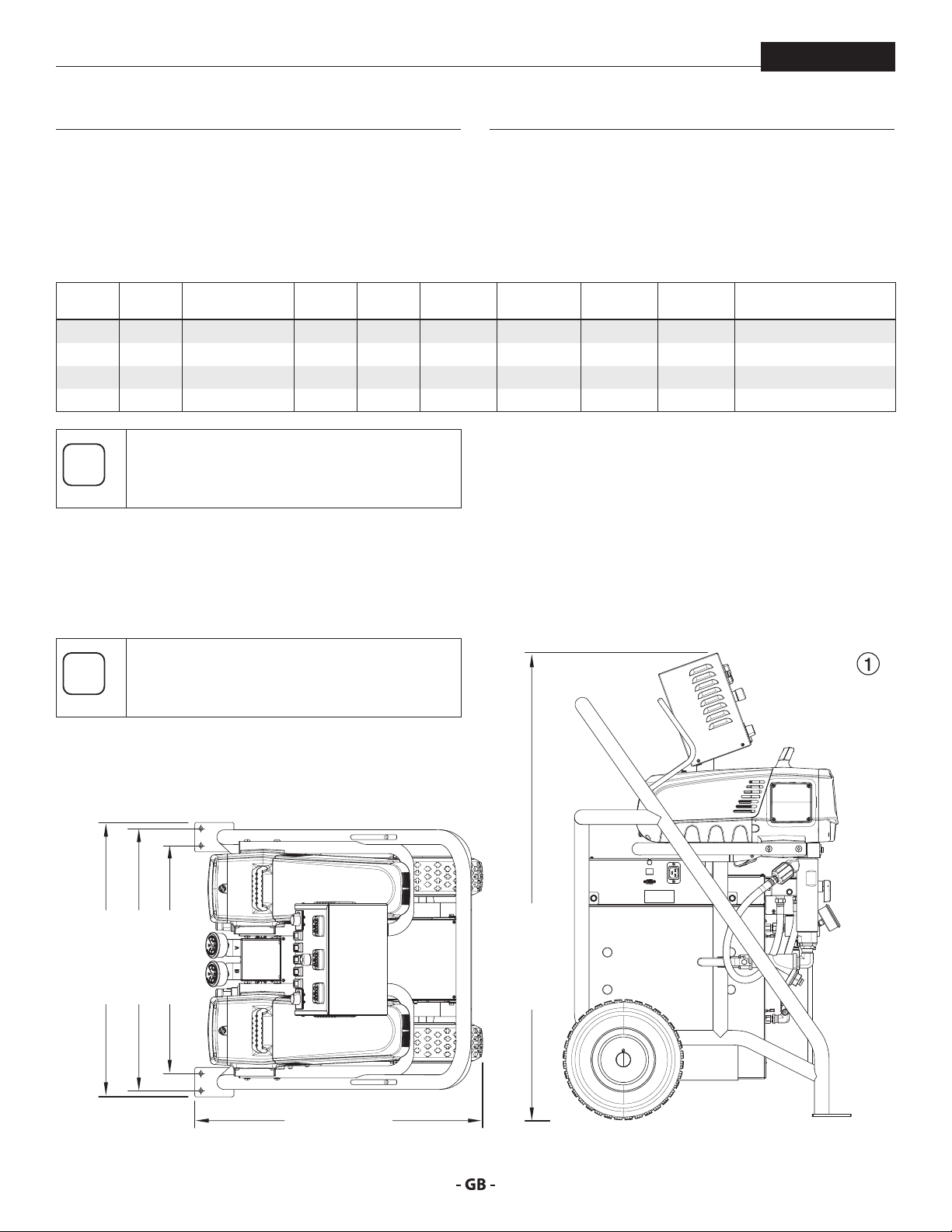
2.2 CLEARANCE DIAGRAM
When determining the location of the Helix
system, use the diagram below to determine
space clearance and mounting hole dimensions.
26.7” (678 mm)
28” (711 mm)
23.2” (589 mm)
47.2” (1199 mm)
29.4” (747 mm)
8
Page 9
general DeSCription
i
i
i
At
HELIX
2.3 ELECTRICAL / GENERATOR REQUIREMENTS
It is recommended that the Helix System be used
with a generator. This provides the exibility
with not having to use the public power grid.
When connected to the public, low-voltage
network, it is possible that an approval of
the network operator is required. Check the
regulations in your country and contact your
network operator before connecting the unit to
a public electricity grid.
The Helix System requires a 208-240V capacity.
Make sure the power source is rated to this
specication.
When working at altitudes above 2100m, check
the generator manufacturer’s specications for
power loss oset.
If powering the Helix system with a generator,
make sure the generator has ample power to
tention
Follow the steps below to determing if your generator is able to
supply sucient power to the Helix system.
1. Perform this equation:
System Watts 13,300 x 1.25 = kVA (kilovolt / amperes)
2. If your generator’s kVA rating is higher than what was
If your generator’s kVA rating is lower than what was
run the system. An inadequate generator will
cause RPM uctuations in the Component Pump
motors during usage and can cause damage.
determined in the equation above, the generator will be
able to power the system.
determined in the equation above, the generator WILL
NOT be able to power the system. A larger generator is
required.
9
Page 10
SYStem DeSCription
L
3 SYSTEM DESCRIPTION
HELIX
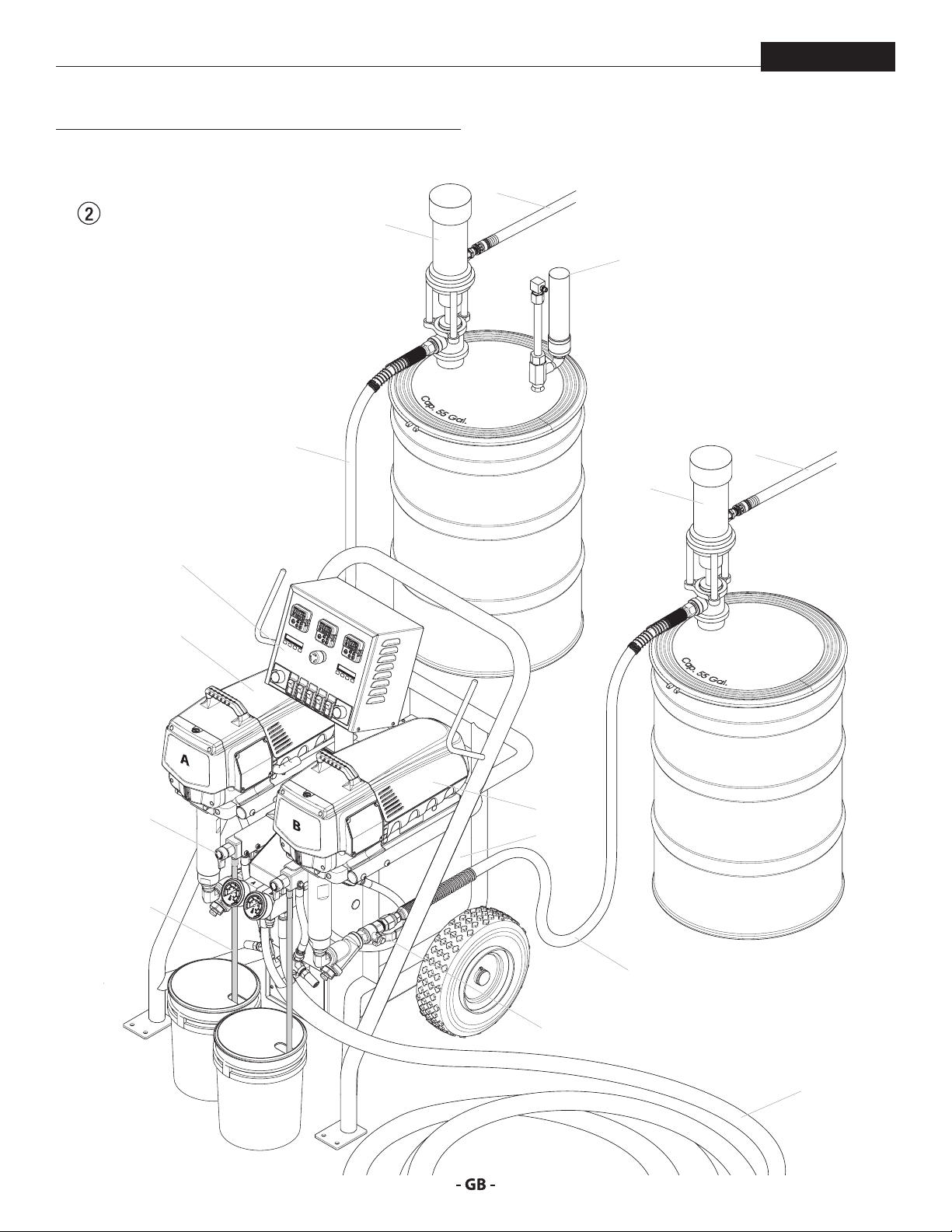
3.1
SYSTEM DIAGRAM WITHOUT CIRCULATION
J
H
D
K
L
J
A
E
F
B
C
H
G
Waste containers
(not included) must
be closed at the top.
10
I
Page 11

SYStem DeSCription
HELIX
3.2 COMPONENT DESCRIPTION WITHOUT CIRCULATION
ITEM DESCRIPTION FUNCTION
A Component Pump A In a two-component system, Component Pump A typically pumps the ISO or activator
material.
B Component Pump B In a two-component system, Component Pump B typically pumps the resin material.
C Surere™ Heater Block Material ows from the supply containers into the uid pumps, where the material is
pressurized to the desired pressure(s), based on the Control Panel settings. The Surere™
heater block heats the material on its way to the material pumps.
D Control Panel The control panel contains all of the system controls that allow the sprayer to function
properly, as well as being the main display panel that gives information about the
system.
E PRIME/SPRAY knob The PRIME/SPRAY knob directs material to the spray hose when in the SPRAY position
and to the prime hoses when in the PRIME position. Turning the PRIME/SPRAY knob will
relieve any pressure built up in the system.
F Prime hoses When the PRIME/SPRAY knobs are set to PRIME, spray material will circulate into the
Component pumps and then out of the prime hoses.
G Inlet valves The inlet valves allow material to be drawn from the material containers into the system.
They can be turned o in order to prevent material from entering the system.
H Supply hoses The two supply hoses deliver uid from the supply drums to the Component pumps.
I Dual heated hose The dual heated hose delivers spray material from the two Component Pumps to the
spray gun.
J Transfer pump The two transfer pumps pump material from the supply containers, into the supply
hoses and then to the Component Pumps. The transfer pumps are powered by an air
compressor.
K Desiccant dryer The Desiccant dryers remove any moisture that is present in the air pockets left by the
removal of material from the supply drums.
L Transfer pump air hose The transfer pump air hose delivers air from the compressor to the transfer pumps.
11
Page 12
SYStem DeSCription
K
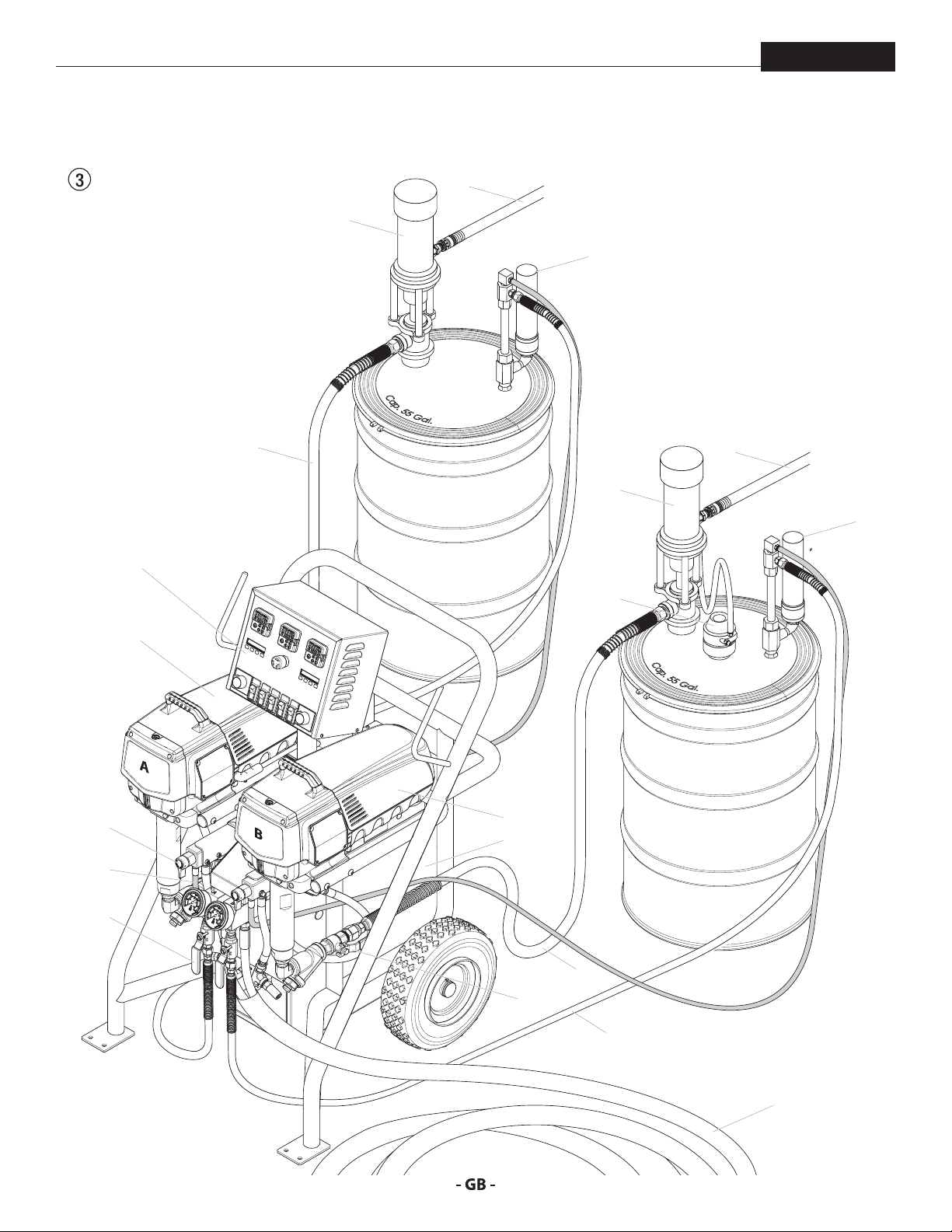
3.3 SYSTEM DIAGRAM WITH CIRCULATION
J
HELIX
M
K
H
J
D
N
A
E
F
B
C
M
12
L1
H
G
L2
I
Page 13
SYStem DeSCription
i
i
HELIX
3.4 COMPONENT DESCRIPTION WITH CIRCULATION
This conguration is only possible with the purchase of
circulation kit P/N 0138914, sold separately. The parts
included in the kit are labeled with an asterisk (*).
ITEM DESCRIPTION FUNCTION
A Component Pump A In a two-component system, Component Pump A typically pumps the ISO or activator material.
B Component Pump B In a two-component system, Component Pump B typically pumps the resin material.
C Surere™ Heater Block Material ows from the supply containers into the uid pumps, where the material is pressurized to
the desired pressure(s), based on the Control Panel settings. The Surere™ heater block heats the
material on its way to the material pumps.
D Control Panel The control panel contains all of the system controls that allow the sprayer to function properly, as
well as being the main display panel that gives information about the system.
E PRIME/SPRAY knob The PRIME/SPRAY knob directs material to the spray hose when in the SPRAY position and to the
prime hoses when in the PRIME position. Turning the PRIME/SPRAY knob will relieve any pressure
built up in the system.
F Prime hoses When the PRIME/SPRAY knobs are set to PRIME, spray material will circulate into the Component
pumps and then out of the prime hoses.
G Inlet valves The inlet valves allow material to be drawn from the material containers into the system. They can
be turned o in order to prevent material from entering the system.
H Supply hoses The two supply hoses deliver uid from the supply drums to the Component pumps.
I Dual heated hose The dual heated hose delivers spray material from the two Component Pumps to the spray gun.
J Transfer pump The two transfer pumps pump material from the supply containers, into the supply hoses and then
to the Component Pumps. The transfer pumps are powered by an air compressor.
K Desiccant dryer The Desiccant dryers remove any moisture that is present in the air pockets left by the removal of
material from the supply drums.
L* Circulation valves / hoses When open, the circulation valves (L1) allow material to circulate through the heater block and
back through the hoses (L2) into the supply containers. This allows the material to be heated more
quickly.
M Transfer pump air hose The transfer pump air hose delivers air from the compressor to the transfer pumps.
N Agitator The agitator stirs the material on the resin (B) side material container.
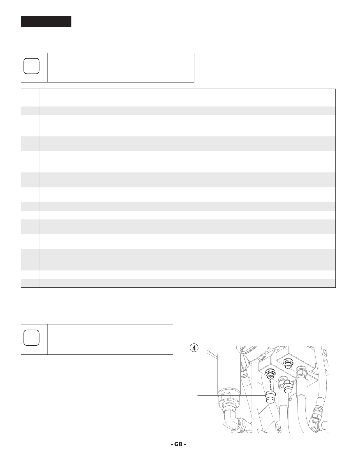
3.5 INSTALLING THE CIRCULATION KIT
OPTIONAL
The circulation kit is available for separate
purchase. Follow the steps below to install it.
Refer to section 2.2 for Clearance Diagram.
1. Make sure the system is turned o and depressurized.
2. Remove the two inlet plugs (Fig. 4, item 1) from the bottom
of the hose heater manifold. Remove return tubes (2).
3. Thread a shut-o valve (Fig. 3, item L1) from the circulation
kit into each of the ports underneath the hose heater
manifold. Thread the longer return tubes (Fig. 2, item F)
underneath each of the PRIME/SPRAY valve manifolds.
4. Attach a hose to each of the shut-o valves. Run the
hoses (Fig. 3, item L2) and return hoses (Fig. 3, item F)
13
back towards the material containers and thread into their
respective ports on the desiccant dryers.
1
2
Page 14
Control panel
i
854 45
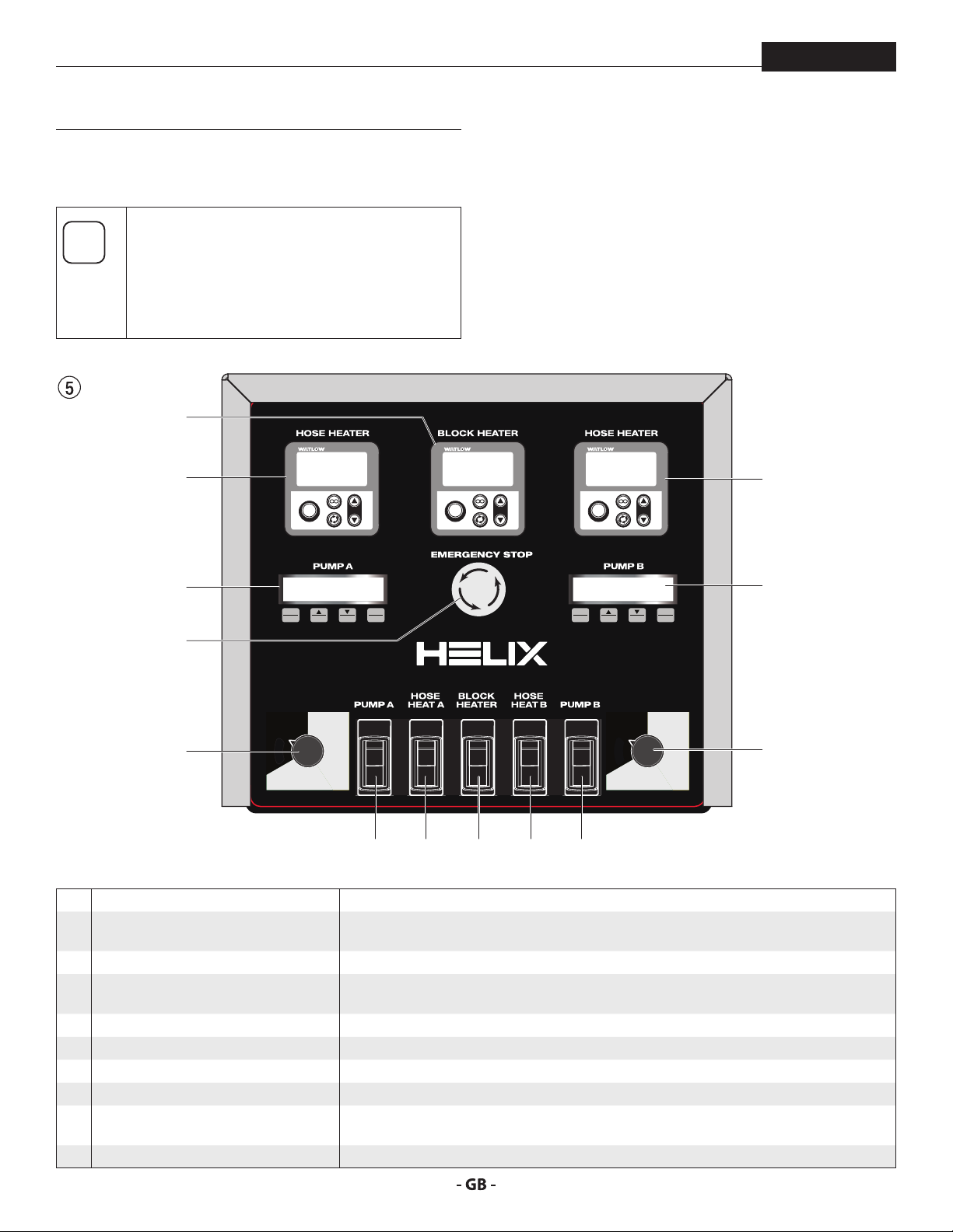
4 CONTROL PANEL
The control panel contains all of the system controls that allow
the sprayer to function properly, as well as being the main
display panel that gives information about the system.
Items 1 - 5 below are duplicated - one for each
pump. If they are located on the left side of the
panel, they serve the “A” side of the system. If
they are located on the right, they serve the “B”
side. If it is located in the middle, it serves the
entire system.
6
HELIX
1a
2a
7
3a
MAX
MENU
1
Clean
MAX
PSI
PSI
EZ-ZONE
8.8:8.8
Z
O
N
8 8.8:8.8
E
EZ
2 3
MIN
MIN
PSI
PSI
EZ-ZONE
1
ºF
ºC
8.8:8.8
Z
O
N
8 8.8:8.8
E
EZ
1
ºF
ºC
EZ-ZONE
8.8:8.8
Z
O
N
8 8.8:8.8
E
EZ
1
ºF
ºC
1b
2b
SEL
4
MENU
1
2 3
SEL
4
Clean
MIN
MIN
PSI
PSI
3b
MAX
MAX
PSI
PSI
1 Heated hose temperature control This panel regulates the spray material temperature for the applicable heated hose.
2 Control Displays The displays show various menu screens that allow the user to customize and monitor pump
operation using the function keys (1 - 4).
a A-side independent controller When the component pumps are unlinked, this controls Component Pump A.
b Master controller / B-side independent
controller
When the component pumps are linked, the master controller controls both component
pumps. When the component pumps are unlinked, this controls Component Pump B only.
3 Component pump pressure control Adjusts the pump pressure of the applicable Component Pump.
4 ON/OFF switch, Component Pump This switch turns the applicable Component Pump ON and OFF.
5 ON/OFF switch, hose heater This switch turns the applicable hose heater ON and OFF.
6 Surere™ heater block control This panel regulates the temperature of the Surere™ heater block
7 Emergency Shuto Pushing this button will instantly shut down the system. However, pressing this button
WILL NOT depressurize the system. Follow the Pressure Relief Procedure.
8 ON/OFF switch, heater block This switch turns the heater block ON and OFF
14
Page 15
Control panel
i
i
i
i
i
HELIX
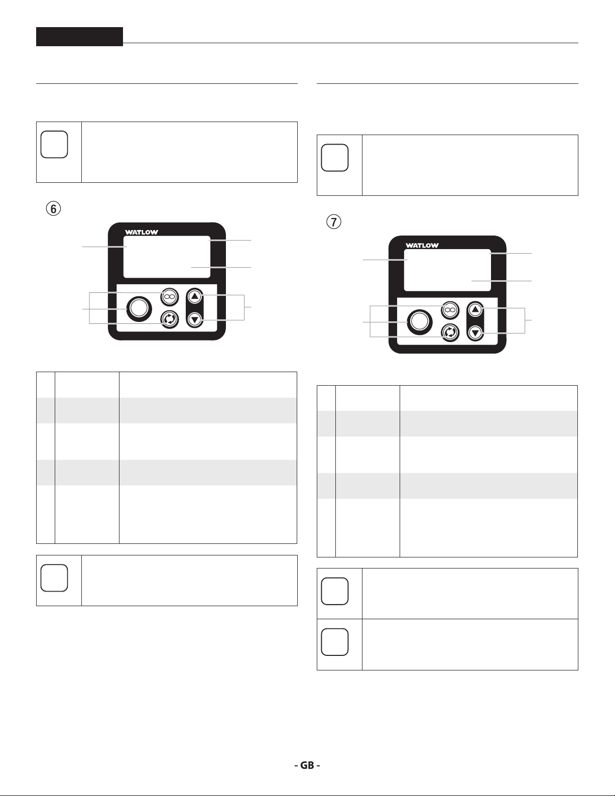
4.1 SUREFIRE™ HEATER BLOCK CONTROL
Refer to item 8 in section 4. The block heater
control regulates the temperature of spray
material as it passes through the heater block,
prior to it reaching the heated hoses.
1
2
1 Temperature
display
2 Programming
buttons
3 Power
indicator
4 Temperature
setting
5 Temperature
adjustment
EZ-ZONE
8.8:8.8
Z
O
N
8 8.8:8.8
E
EZ
Shows actual temperature of the heater
block.
These are non-functioning factory
programming buttons. Do not use.
The ashing or steady “1” indicates sucient
power is being delivered to the system’s
electrical relay.
Shows the desired temperature of the heater
block set by the operator
These buttons will increase ( p) or decrease
( q ) the temperature of the heater block.
The temperature will change in increments
of 1ºF. Press and hold the button to increase
the increments by 1ºF and then 10ºF.
1
ºF
ºC
4.2 SUREFIRE™ HEATED HOSE TEMPERATURE
CONTROL
Refer to item 1 in section 4. The heated hose
temperature control maintains the temperature
of the spray material once it passes through the
heater block and into the heated hoses.
3
4
1
8.8:8.8
Z
O
N
8 8.8:8.8
E
5
2
1 Display Displays the current temperature of the
2 Programming
buttons
3 Power
indicator
4 Temperature
setting
5 Temperature
adjustment
EZ
heated hose set
These are non-functioning factory
programming buttons. Do not use.
The ashing or steady “1” indicates sucient
power is being delivered to the system’s
electrical relay.
Shows the desired temperature of the
heated hoses set by the operator
These buttons will increase ( p) or decrease
( q ) the temperature of the heated hose set.
The temperature will change in increments
of 1ºF. Press and hold the button to increase
the increments by 1ºF and then 10ºF.
EZ-ZONE
1
ºF
ºC
3
4
5
Refer to section 8.2 to review the controller error
messages.
15
Refer to section 8.2 to review the controller error
messages.
Decreased voltage under 230V AC may increase
initial heat time.
Page 16
Control panel
i
i
i
i
HELIX
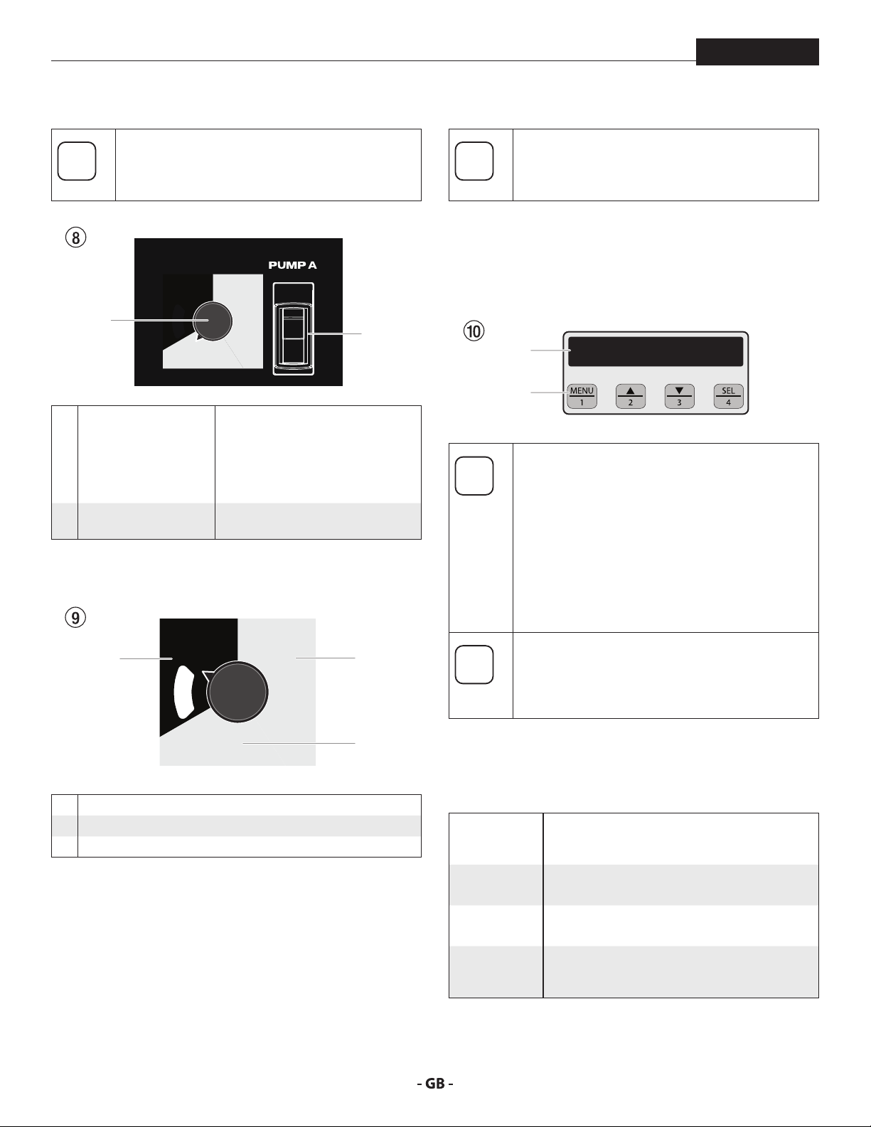
4.3 COMPONENT PUMP PRESSURE CONTROL
Refer to item 2 in section 4. The following items
control the pressure of the individual Component
Pumps.
MIN
PSI
1
MAX
PSI
1 Pressure control knob Adjusts the pump pressure of the
applicable Component Pump when
unlinked. When Component pumps
are linked, the (B) pump pressure
control knob will control the
pressure of both pumps.
2 Component Pump ON/
OFF switch
PRESSURE CONTROL KNOB SETTINGS
Switches the Component Pump ON
and OFF.
MIN
PSI
2
2
1
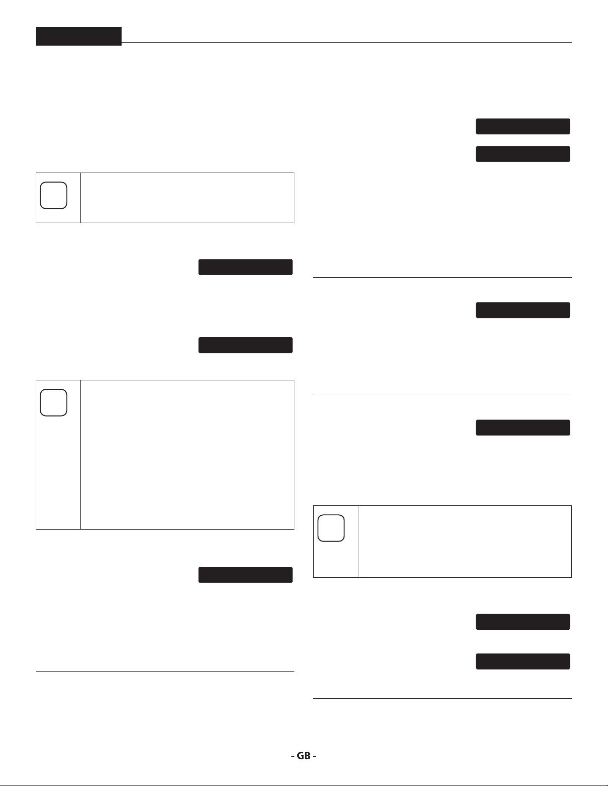
4.4 CONTROL DISPLAYS
Refer to item 2 in section 4. The graphic below
applies to both the Component Pump (A) and
Component Pump (B).
The Control Displays increase the functionality of the applicable
Component Pump.
It consists of a display (1) and four function keys (2). The display
shows various menu screens that allow the user to customize
and monitor sprayer operation using the function keys.
1
2
When both component pumps are turned
ON, the system will automatically link the two
Component Pumps after 10 seconds. This means
the Component Pump (A) control display will be
controlled by the Component Pump (B) control
display. When the component pumps are linked,
the Component Pump (A) control display keys
are disabled and will only be functional when the
two Component Pumps are unlinked (see “Status
Screen”).
The pressure control knob overrides the Control
Display settings. Anytime the pressure control
knob is turned, the sprayer pressure will change
accordingly.
SET PSI 0
ACTUAL PSI 0
MAX
PSI
1 Minimum pressure setting
2 Black zone – no pressure generation
3 Maximum pressure setting
16
3
FUNCTION KEYS
The function keys are numbered 1–4. Each key is labeled with
an additional function as well.
#1/Menu Key Pressing the #1 key scrolls through the available
menu screens or performs a function described on
the active menu screen.
#2/p Key
#3/q Key
#4/Select Key Pressing the #4 key selects the active menu screen
Pressing the #2 key performs a function described
on the active menu screen or increases a value.
Pressing the #3 key performs a function described
on the active menu screen or decrease a value.
or performs a function described on the active
menu screen.
Page 17
Control panel
i
SET PSI 0
L-SET PSI 0
ACTUAL PSI 0
i
VIS-COMP NEXT-1 +2 -3
STATUS = LINKED
STATUS = UNLINKED
ALARM RANGE
+/- 750 PSI
ALARM STATUS: OFF
i
TOTAL CYCLES
SELECT-4MENU-1
CYCLES XXXX
RESET-3MENU-1
HELIX
MENU SCREENS
Several menu screens are available for the user to customize
and monitor sprayer operation. They include Main Screen, VisComp (Viscosity Compensation)*, Status* Alarm Range*, Alarm
Status*, Total Cycles*, Job Cycles*, Unit Serial #, Timers, Job
Timers, Service Time, Security Code*, and Prime.
Screens noted with an asterisk (*) are screens that
apply to Component Pump (B) only. All other
screens apply to both (A) and (B) pumps.
Main Screen
The Main Screen is the default screen
for the control system at sprayer
startup.
Pressing the #2 key switches between PSI, Bar, and MPa units
of measure. Press the #1 key to scroll through the remaining
menu screens.
(A) Pump Only - The “L-” before the
“Set PSI” text on the Main Screen
indicates that the two Component Pumps are linked.
For sprayers equipped with an nine-language
Control Display:
Pressing the #2 key at the Main Screen switches
between PSI, Bar and MPa units of measure.
Pressing the #3 key at the Main Screen changes
the language of the text on the display. There
are a total of nine languages available. Each time
the #1 key is pressed, a dierent language will
appear. The languages, in order of appearance,
are: English, Spanish, Dutch, Danish, Swedish,
German, French, Italian, and Portuguese.
Vis-Comp (Viscosity Compensation) Screen*
The Vis-Comp screen on the (B) pump
allows the user to see and/or adjust
slight dierences in viscosity between the (A) pump material
and the (B) pump material.
Pressing the #2 key will increase the spraying ratio in
increments of 1% (up to 5%). Pressing the #3 key will decrease
the spraying ratio in increments of 1% (up to 5%). Pressing the
#4 key will increase the ratio by increments of .250.
ACTUAL PSI 0
1%
Status Screen*
The Status Screen shows the link
status of the (A) pump and (B) pump.
When turning the system on, the two
pumps will automatically be linked,
which means the (A) pump is controlled by the (B) pump.
When the Status Screen is showing, pressing the #3 key will
unlink the two pumps, and the (A) pump and (B) pump will
operate independently and the (A) pump control display keys
will be enabled.
If the pumps have been unlinked, pressing the #2 key will link
the two pumps back together, and the (A) pump will now be
controlled by the (B).
Alarm Range Screen*
The Alarm Range Screen allows the
user to adjust the allowable pressure
discrepancy between the (A) and (B) pumps.
Pressing the #2 key will increase the allowable pressure
discrepancy by 50 psi. Pressing the #3 key will decrease the
allowable pressure discrepancy by 50 psi. The range is 250 psi
- 1000 psi.
Alarm Status Screen*
The Alarm Status Screen allows
the user to switch ON or OFF the
internal alarm that alerts the user to a non-allowable pressure
imbalance.
Pressing the #2 key will turn the alarm ON. Pressing the #3 key
will turn the alarm OFF.
If a pressure imbalance is detected in the system
with the alarm status set to ON, the system will
automatically shut down and the display will
show a PSI Imbalance. Refer to Control Display
Error Messages.
Total Cycles Screen*
The Total Cycles Screen shows the
total number of piston cycles a
component pump has performed during its lifetime.
Pressing the #3 key will reset the
cycle count to zero. Pressing the #1
key will bring the control panel back to the Main Screen.
LINK-2 UNLINK-3
LINK-2 UNLINK-3
ON-2 OFF-3 EXT-4
17
Page 18

Control panel
SECURITY CODE
i
ENTER OLD CODE
ENTER NEW CODE
i
PRIME
i
JOB CYCLES
CYCLES XXXX
UNIT SERIAL #
SELECT-4MENU-1
SER # XXXXXXXXXX
MENU-1
TIMERS
ON TIME
XXXX
JOB TIMERS
SELECT-4MENU-1
JOB ON X
SERVICE TIME
SERVICE @ XX
HELIX
Job Cycles Screen*
The Job Cycles Screen shows the total
number of piston cycles a component
pump performs during a spray job.
Pressing the #3 key will reset the
cycle count to zero. Pressing the #1
key will bring the control panel back to the Main Screen.
Unit Serial # Screen
The Unit Serial # screen shows the
sprayer’s serial number.
To select the Unit Serial # screen,
press the #4 key.
Timers Screen
The Timers screen shows the total
time the sprayer has been turned on
as well as the total time the sprayer
has been running (pumping).
To select the Timers screen, press the
RUN TIME
#4 key.
Job Timers Screen
The Job Timers screen allows the
user to reset the “ON TIME” and “RUN
TIME” to track time on specic jobs.
To select the Job TImers screen, press
the #4 key. “JOB ON” screen will
appear. Press #3 to reset. Press #1 to
JOB RUN X
continue to “JOB RUN” screen. Press
#3 to reset. Press #1 to scroll through the remaining menu
screens.
Service Time Screen
The Service Time screen allows the
user to set a service time interval
(in hours). Below the set time, the
screens shows the current amount
of hours on the sprayer since the last
activation of the service timer. To select the Service Timer
screen, press the #4 key.
To set the service time, press the #2
RUN HOURS XX
(up) and/or the #3 (down) keys to the
desired time (run hours will increase/
decrease in increments of 1 for each
time you press a key).
When the service time interval is set and met by the run hours,
the display will show a “Service Required” screen. The pump
will remain functional. To return to the Main Screen, press the
#1 key. Doing so will reset the “Service @” and “Run Hours”
displayed on the Service Screen back to 0.
18
Security Code Screen*
SELECT-4MENU-1
The Security Code screen allows the
CHANGE-2MENU-1
user to set a four digit security code
to prevent unauthorized use of the sprayer. If a security code
RESET-3MENU-1
has been set, the control system display will ask for the code
at startup. If the correct code is entered, the display will show
the Main Screen and the sprayer will operate. If the wrong
code is entered, the display will continue to ask for the correct
code and the sprayer will be disabled. To set or change the
security code, press the #2 key.
If the sprayer is new, no security code is set and
the Main Screen will appear at startup. When
setting a security code for the rst time, the
“Enter Old Code Number” screen will appear, and
you will need to enter “1111”.
SELECT-4MENU-1
Enter the old security code number
NUMBER
to access the screen that allows the
code change. If the wrong code is
XXXX
entered, the display will continue
to ask for the correct code and the security code cannot be
changed.
Enter the new security code. Once
the new code is entered, the display
will automatically ask that the new
code be re-entered for verication.
If the same new code is re-entered,
RESET-3MENU-1
the display will conrm that the new
NUMBER XXXX
RE-ENTER NEW
NUMBER XXXX
NEW CODE NUMBER
ACCEPTED
code has been accepted and return to the Main Screen. If the
RESET-3MENU-1
new code is re-entered incorrectly, the display will return to
the “Enter New Code Number” screen and the process will
repeat.
If you forget or misplace your security code, you can call Titan
customer service for assistance.
SELECT-4MENU-1
To inactivate the Anti-Theft Digital Lockout
security function, enter “1111” at the “Enter New
Code Number” screen (this is the default code
that leaves the sprayer unlocked). As a result, the
Main Screen will appear at sprayer startup.
Prime Screen
The Prime screen appears when the
pressure control knob is set at the
“MIN” setting.
If there is no action at any menu screen for 10
seconds, the display will go back to the Main
Screen.
Page 19

Control panel
CHECK
TRANSDUCER
CHECK
LOW
VOLTAGE
HIGH MOTOR
TEMPERATURE
HIGH MECHANICAL
PSI IMBALANCE
UNLINK 3
HELIX
4.5 CONTROL DISPLAYS ERROR MESSAGES
The following error message screens appear whenever the
Control Display detects a problem with the system. Once a
problem occurs and the error message appears, the system will
shut down.
Before proceeding, follow the Pressure Relief
Procedure outlined in this manual. Additionally,
follow all other warnings to reduce the risk of
an injection injury, injury from moving parts or
electric shock. Always unplug the system before
servicing!
Check Transducer Screen
The Check Transducer screen appears
when the transducer has become
disconnected or is defective. Take the sprayer to a Titan
authorized service center for repair.
Check Potentiometer Screen
The Check Potentiometer screen
POTENTIOMETER
appears when the potentiometer has
become disconnected or is defective. Take the sprayer to a
Titan authorized service center for repair.
Low Voltage Screen
The Low Voltage screen appears
when the sprayer shuts down
because of low input voltage. Check the power supply and
correct the problem. Restart the system.
High Motor Temperature Screen
The High Motor Temperature screen
appears when the temperature of
the motor has risen too high. Take the sprayer to a Titan
authorized service center for repair.
High Mechanical Load
The High Mechanical Load screen
LOAD
appears when the sprayer shuts
down because of high current or when the sprayer goes into
current fold back mode. Take the sprayer to a Titan authorized
service center for repair.
PSI Imbalance
The PSI Imbalance screen appears
when there is a non-allowable
pressure discrepancy between the (A) and (B) pumps while
linked. If a PSI imbalance occurs, press the #3 key to unlink the
two pumps. Once the pumps are unlinked, press the #1 key to
return to the Main Screen.
19
Page 20

Setup
i
i
i
HELIX
5 SETUP
In order to prevent accidental startup, make sure
the system’s power cord is not connected during
setup, until instructed to do so.
Make sure the air pressure supply is shut o while
connecting any air hoses to the air supply.
5.1 LOCATE THE SYSTEM
1. Locate the system on a level surface. Refer to dimensions
in section 2.2 for clearance and mounting hole dimensions.
2. Mount in a dry area.
3. For best results, the machine should be bolted into place.
5.2 INSTALL THE TRANSFER PUMPS
The transfer pumps draw material directly from
the spray material container to component
pumps in the system. The transfer pumps are
powered by an air compressor.
5. Attach the transfer pump air hose to their individual air
ttings.
6. Connect the other end of the transfer pump air hose to the
powered air pressure supply.
Do not install shuto valves downstream of the
prime tubes. The PRIME/SPRAY valves function
as overpressure relief valves when set to SPRAY.
Refer to section 3.1 for the corresponding illustrations to the
steps below.
1. Install the transfer pumps into Component A and
Component B supply containers.
a. With certain exceptions, the “A” component (hardener)
b. With certain exceptions, the “B” component (resin)
2. Seal the container holding Component A material and
3. If necessary, install an agitator into the Component B
4. Make sure the Component A and Component B inlet
should be located on the “A” side of the system.
should be located on the “B” side of the system.
Consult the spray material’s manufacturer
if you are unsure about which Component
Pump is compatible with each individual spray
component.
install the desiccant dryer in the vent hole.
material container.
valves are in the closed position (handle should be 90º to
the valve).
20
Page 21

Setup
At
i
AB
At
HELIX
5.3 CONNECT THE SUREFIRE™ HEATED HOSES
CONNECT THE HEATED HOSES
The heated hose assembly and dual whip hose
come pre-installed with the system and should
tention
1. Attach the JIC ttings (packaged separately with the
a. Connect the smaller JIC tting to the “A” side whip hose.
b. Connect the larger JIC tting to the “B” side whip hose.
2. Remove the coupling block from the spray gun (refer to
3. Close gun manifold valves A and B.
tention
not be removed or disassembled unless it is
being completely replaced.
Refer to the Helix Surere™ Dual Heated Hose
Manual included with your system.
heated hose set) to their appropriate whip hoses.
the spray gun manual).
Always close the manifold valves if the system is
idle for more than 1 minute under heat and/or
pressure. Failure to do so can cause a pressure
imbalance which can then lead to a material
“crossover” inside the gun, leaving the gun
inoperable.
4. Attach the dual heated whip hose to the coupling block.
a. Secure the “A” hose to the “A” side of the coupling block.
b. Secure the “B” hose to the “B” side (or “R” side) of the
coupling block.
B (Resin)
A (ISO)
5. Tighten both hose connections with a wrench.
CONNECT THE SUPPLY HOSES
1. Make sure the valve handles on the inlet valves for both
Component pumps are in the OFF position (see g. 11).
2. Attach one end of the feed hose to the inlet valve of
Component pump A. Repeat for Component pump B with
another hose.
3. Connect the other end of each hose to their appropriate
transfer pumps (i.e. the “A” hose should run from
Component pump A to the transfer pump installed into
material supply drum “A”).
4. Make sure all connections are wrench tight.
5. Arrange the return hoses:
a. For non-circulation congurations (see gure 2, section
3.1), place a waste bucket underneath each of the return
hoses.
b. For circulation conrgurations (see gure 3, section 3.3)
Attach the return hoses tubes to the dessicant dryers of
the appropriate material supply drum (i.e. the “A” return
tube for should run from Component pump A to the
dessicant dryer installed into material supply drum “A”.
21
Page 22

Setup
At
i
i
i
5.4 CONNECT THE ELECTRICAL CORD
HELIX
A 230V power cord is not included with the
system. Make sure a grounded, 230V outlet is
available in order to power the system.
It is recommended that the Helix System be used
with a generator. This provides the exibility
with not having to use the public power grid.
When connected to the public, low-voltage
network, it is possible that an approval of
the network operator is required. Check the
regulations in your country and contact your
network operator before connecting the unit to
a public electricity grid.
Power Cord Connector Requirements
Models 0138010 / 0138061 0138057 / 0138062
Connector Twistlock Twistlock
AMP 50 50
Number of Poles 3 3
Number of Wires 4 4
Phases 1 3
Voltage 125 / 250 VAC 250 V
Recommended
Manufacturer
Pass & Seymour, P/N
CS6364
LEVITON P/N
CS8364
Spray Gun The spray gun is grounded through the whip
hose ground wire. Do not spray without using
the whip hose.
Fluid Supply
Chambers
Object being
sprayed
Waste
Containers
Follow the local code.
Follow the local code.
Follow the local code. Only use metal containers
placed on a grounded surface when ushing the
system. Do not place metal waste containers on
paper or cardboard surface. A non-conductive
surface such as these can interrupt grounding
continuity.
While ushing or relieving system pressure,
ground the gun by holding it against the edge of
the metal container. Failure to do so may lead to
a static electric discharge, which may cause a re.
5.6 LUBRICATE THE COMPONENT PUMPS
1. Remove the cup cap with a straight-slot screwdriver.
2. Fill the cup reservoir with DOP (Dioctylphthalate) or
compatible plasticizer (Fig. 15) until the gauge (1) is
showing that it is full.
If using a generator to power the system, refer to
section 2.2 prior to plugging in the power cord.
1. First plug the adapter end of the supplied power cord
into the power cord port located on the side of the block
heater.
2. Plug the other end of the supplied power cord into a
grounded, 230V outlet.
5.5 GROUND THE SYSTEM
Proper grounding (earthing) is important. The
passage of some materials through the nylon
uid hose will build up a static electric charge,
which if discharged, could ignite solvent vapors
present and create an explosion.
Component Grounding Method
System The system and heated hoses are grounded
through the power cord.
DOP (Dioctylphthalate) or a compatible
plasticizer prevents increased wear and tear to
tention
3. Replace cup cap.
4. Press button (2) 2-5 times to prime the dispenser. Press
the packings and will keep spray material from
crystalizing on the uid section.
once for every eight hours of usage to lubricate and
protect the uid section.
1
2
22
Page 23

operation
At
At
i
i
i
HELIX
6 OPERATION
Prior to startup, make sure the generator has
fuel. Running out of fuel will cause electrical
tention
uctuations in the system that could result in
damage to the electrical components of the
system.
6.1 STARTUP
1. If using a generator, make sure the main breaker on the
generator is in the OFF position.
2. If using a generator, start the generator. Allow it to run to
full power.
3. If using an air compressor to power the transfer pumps,
start the compressor, making sure the bleed valve is in the
closed position on the compressor.
4. Turn the breaker on the generator to ON. Switch both of
the Component Pump ON/OFF switches to ON. (these are
the outermost ON/OFF switches located on the control
panel).
Do not turn on the block heater or hose heater
ON/OFF switches ON yet. Turning the hose
tention
heaters on when there is no uid in the hoses can
cause damage to the hoses.
6.2 SET TEMPERATURE
Refer to section 4 to review temperature controls.
Equipment surfaces can become hot. To avoid
severe burn injury:
1) Do not touch hot uid or equipment.
2) Allow equipment to cool completely
3) Wear gloves when dealing with
1. Set the temperature of the heater block:
a. Switch the heater block ON/OFF switch to ON (this is the
ON/OFF switch in the middle of the control panel).
b. Using the heater block controls, set the heater block
to the desired temperature. Press the (p) button
until the bottom set of numbers (1) shows the desired
temperature.
before coming into contact with it.
temperatures in excess of 110ºF (43ºC)
EZ-ZONE
65
Z
O
N
8 110
E
1
ºF
ºC
2
13
5. Turn the PRIME/SPRAY valves on both of the Component
Pumps to SPRAY.
6. Open the uid inlet valves. Check for leaks.
7. Place the coupling block (with hoses attached) over two
separate, grounded waste containers. Make sure the ports
on the manifold each aim into a dierent container.
NEVER mix components A and B during startup.
Use two separate grounded waste containers to
keep Component A and Component B separate.
8. While holding the coupling block over the waste
containers, slowly open uid valves A then B. Allow them
to remain open until clean, air-free uid comes from the
valves.
9. Close uid valves A then B.
23
2. Set the temperature of the heated hoses (repeat each of
a. Switch the heated hose ON/OFF switches to ON (these
b. Using the heated hose controls, set the heated hoses
c. The temperature settings of the heated hoses can also
The top number (2) on the heater block displays
the actual temperature. When the light (3) goes
out, the block heater is suciently heated.
the following steps for both A and B hoses):
are the switches immediately on either side of the heater
block switch in the middle of the control panel).
to the desired temperature. Press the (
until the bottom set of numbers (1) shows the desired
temperature.
be adjusted to balance spraying pressures as well as the
desired Viscosity Compension (Vis-Comp).
Adjusting the hose heat should ONLY be a
secondary method of achieving the correct VisComp. Use the Vis-Comp Screen on the Control
Display rst.
EZ
p)
button
Page 24

operation
i
At
At
HELIX
6.3 SPRAYING
Refer to the safety information in the beginning
of this manual for injury prevention guidelines.
Refer to the safety and operation instructions of
the gun manual.
1. Engage the trigger safety (refer to the spray gun instruction
manual).
2. Make sure the valves A / B on the coupling block are closed.
3. Reattach the coupling block (with hoses attached) to the
spray gun.
4. Connect the end of the air hose that is closest to the
pump to an air supply (the air hose is housed within the
velco sheathing that also contains the dual heated hoses).
Connect the other end of the air hose to the spray gun.
Make sure the air valve on the air hose (if any) is open.
5. Make sure the PRIME/SPRAY valves on the component
pumps are set to SPRAY.
6. Verify that the temperature readings are showing the
desired temperatures.
7. Verify pressure readings:
a. Check pressure gauges mounted on the front of the
system, or
b. For each component pump, go to the Control Display
Main Screen on the control panel.
Always close the manifold valves if the system is
idle for more than 1 minute under heat and/or
tention
pressure. Failure to do so can cause a pressure
imbalance which can then lead to a material
“crossover” inside the gun, leaving the gun
inoperable.
Make sure the Component Pump pressures are
balanced prior to opening the manifold valves
and resuming spraying.
6.4 PRESSURE RELIEF PROCEDURE
Perform the Pressure Relief Procedure when
shutting down for any reason.
1. Engage the trigger safety (refer to the spray gun instruction
manual).
2. Close the manifold valves A and B on the spray gun.
3. Perform all of these steps on both component pumps:
a. Turn the pressure control knob fully counterclockwise to
b. Turn the PRIME/SPRAY knob to PRIME.
4. Disconnect the spray gun air supply line.
minimum.
The pressures shown on either the gauges or the
Control Display Screens should be within 200
PSI. If pressure is unbalanced, unlink the pumps,
and then adjust the pressure to desired balanced
pressure. Once pressure is balanced, re-link the
pumps.
8. Open the coupling block valves A and B on the spray gun.
NEVER open the manifold valves on the coupling
block or trigger the spray gun if the pressure
tention
9. Disengage the trigger safety (refer to the spray gun
10. Test your spray on a piece of scrap wood or cardboard.
readings are unbalanced.
instruction manual).
Adjust pressure and temperatures as necessary to achieve
desired results.
24
Page 25

Shutting Down
At
i
i
HELIX
7 SHUTTING DOWN
7. Turn the ON/OFF switches for both Component Pumps to
It is important to the system’s electrical reliability
to maintain steady electrical voltage during
tention
1. Perform the Pressure Relief Procedure (section 6.4).
2. Turn the block heater ON/OFF switch to OFF (this is the
3. Turn both hose heater A and B ON/OFF switches to OFF
4. Switch o the air compressor and any other auxiliary
5. Open the bleed valve on the air compressor in order to
6. Turn the Component (A) and Component (B) inlet valve
7. Shut down the transfer pumps as required.
shutdown. Failure to follow these procedures
can cause voltage uctuations that can damage
the equipment and void the warranty.
switch located in the center of the control panel).
(these are the switches on either side of the heater block
ON/OFF switch).
equipment, if being used.
relieve pressure and remove any water that may have
formed in the tank.
handles to the closed position (handle should be 90º to
the valve).
7.1 PARKING
OFF.
8. Switch the generator OFF. Allow generator dwell time, per
the manufacturer recommendations.
7.2 FLUSHING
Flush the system in a well-ventilated area. Do
not turn on hose heaters or block heater when
ushing with ammable solvents.
If the new Isocyanate being introduced is
compatible with Polyol, it is not necessary to
ush the (A) side.
1. Flush out the old uid with new uid, or ush the old uid
with a compatible solvents prior to introducing a new
uid (check with the old uid manufacturer in order to
determine a compatible ushing solvent).
2. Always use the lowest possible pressure when ushing the
sprayer. Make sure the Component Pump pressure control
knobs are turned as far counterclockwise as possible in the
“MIN PSI” yellow zone.
3. Use only moisture-free solvents when ushing the system.
Perform the following steps on the (A)
Component Pump ONLY unless otherwise
specied. The following must be done in order
to prevent spray material build-up on the (A) side
Component Pump uid section.
1. Turn the pressure control knob to “MIN PSI” setting in the
yellow zone. The Control Display should say “PRIME”.
2. Press the #1 key on the Control Display. The “CREEP
MODE” screen will now appear.
3. Slowly turn the pressure control knob clockwise to increase
the pressure. The crankshaft/slider assembly will begin to
move very slowly.
4. Wait until the crankshaft/slider starts moving downward.
When it begins its downstroke, turn the Component (A)
PRIME/SPRAY valve to SPRAY.
5. When the crankshaft/slider reaches the bottom, deadcenter of its stroke, turn the pressure control knob fully
counterclockwise. The crankshaft/slider assembly should
stop.
6. Press the cup button 6-8 times to lubricate the piston on
both (A) and (B) Component Pumps.
25
Page 26

troubleShooting
8. TROUBLESHOOTING
HELIX
8.1
COMPONENT PUMPS
Problem Cause Solution
A. The unit will not run. 1. The unit is not plugged in to a power source.
B. The unit will not build or
maintain pressure.
C. Fluid leakage at the upper
end of the uid section.
2. Tripped breaker.
3. The pressure is set too low (pressure control knob
set at minimum setting does not supply power to
unit).
4. Faulty or loose wiring.
5. Excessive motor temperature.
6. ON/OFF switch is defective.
1. The pressure control knob is not set properly.
2. Material ows from the return hose when the
PRIME/SPRAY valve is in the SPRAY position.
3. Air leak in material feed hoses.
4. There is external uid leak.
5. There is an internal uid section leak (packings are
worn and/or dirty, valve balls are worn).
6. Worn valve seats
7. Motor powers but fails to rotate
8. Transfer pumps not supplying material.
1. The upper packings are worn.
2. The piston rod is worn.
1. Plug the power cord into a grounded, 230V outlet.
2. Reset the breaker.
3. Turn the pressure control knob clockwise to
4. Inspect or take to an authorized service center.
5. Allow motor to cool.
6. Replace the ON/OFF switch.
1. Turn the pressure control knob clockwise to
2. Clean or replace the PRIME/SPRAY valve.
3. Check the inlet valve / feed hose connection.
4. Check for external leaks at all connections.
5. Clean the valves and service the uid section
6. Reverse or replace the valve seats following the
7. Take unit to a authorized service center.
8. Check air supply and valves, or service the transfer
1. Repack the pump following the steps in section
2. Replace the piston rod following the steps in
supply power to the unit and increase the
pressure setting.
increase the pressure setting.
Tighten or wrap the threads with Teon tape.
Tighten connections, if necessary.
following the steps in section 9.5 and 9.6 in this
manual.
steps in section 9.5 and 9.6 in this manual.
pumps.
9.5 and 9.6 in this manual.
section 9.5 and 9.6 in this manual.
26
Page 27

troubleShooting
HELIX
8.2 SUREFIRE™ HEATER BLOCK / HOSE HEATER CONTROLLER ERRORS
Problem Cause Solution
A. Alarm will not clear or Reset with
keypad or digital input.
B. Alarm will not activate output. 1. Alarm silencing is active
C. Alarm Error. Alarm status cannot
be determined due to a lack of
sensor input.
AL.E 1 AL.E 2 AL.E 3 AL.E 4
D. Alarm Low. Sensor input below
low alarm set point.
AL.L 1 AL.L 2 AL.L 3 AL.L 4
1. Alarm latching is active
2. Alarm set to incorrect output
3. Alarm is set to incorrect source
4. Sensor input is out of alarm set point range
5. Alarm set point is incorrect
6. Alarm is set to incorrect type
7. Digital input function is incorrect
2. Alarm blocking is active
3. Alarm is set to incorrect output
4. Alarm is set to incorrect source
5. Alarm set point is incorrect
6. Alarm is set to incorrect type
1. Sensor improperly wired or open
2. Incorrect setting of sensor type
3. Calibration corrupt
1. Temperature is less than alarm set point
2. Alarm is set to latching and an alarm occurred
in the past
3. Incorrect alarm set point
4. Incorrect alarm source
1. Reset alarm when process is within range or
disable latching
2. Set output to correct alarm source instance
3. Set alarm source to correct input instance
4. Correct cause of sensor input out of alarm
range
5. Set alarm set point to correct trip point
6. Set digital input function and source instance
1. Disable alarm silencing, if required
2. Disable alarm blocking, if required
3. Set output to correct alarm source instance
4. Set alarm source to correct input instance
5. Set alarm set point to correct trip point
6. Set alarm type to correct type
1. Correct wiring or replace sensor
2. Match setting to sensor used
3. Check calibration of controller
1. Check cause of under temperature
2. Clear latched alarm
3. Establish correct alarm set point
4. Set alarm source to proper setting
E. Alarm High. Sensor input above
high alarm set point.
AL.H 1 AL.H 2 AL.H 3 AL.H 4
F. Error Input. Sensor does not
provide a valid signal to controller
Er. ,1
G. Limit will not clear or Reset with
keypad or digital input
H. Limit Error. Limit status cannot be
determined due to a lack of sensor
input, limit will trip.
L ,.E 1
I. Limit Low. Sensor input below low
limit set point.
L ,.L 1
J. Limit High. Sensor input above
high limit set point.
L ,.h 1
1. Temperature is greater than alarm set point
2. Alarm is set to latching and an alarm occurred
in the past
3. Incorrect alarm set point
4. Incorrect alarm source
1. Sensor improperly wired or open
2. Incorrect setting of sensor type
3. Calibration corrupt
1. Sensor input is out of limit set point range
2. Limit set point is incorrect
3. Digital input function is incorrect
1. Sensor improperly wired or open
2. Incorrect setting of sensor type
3. Calibration corrupt
1. Temperature is less than limit set point
2. Limit outputs latch and require Reset
3. Incorrect alarm set point
1. Temperature is greater than limit set point
2. Limit outputs latch and require Reset
3. Incorrect alarm set point
1. Check cause of over temperature
2. Clear latched alarm
3. Establish correct alarm set point
4. Set alarm source to proper setting
1. Correct wiring or replace sensor
2. Match setting to sensor used
3. Check calibration of controller
1. Correct cause of sensor input out of limit range
2. Set limit set point to correct trip point
3. Set digital input function and source instance
1. Correct wiring or replace sensor
2. Match setting to sensor used
3. Check calibration of controller
1. Check cause of under temperature
2. Clear limit
3. Establish correct limit set point
1. Check cause of over temperature
2. Clear limit
3. Establish correct limit set point
27
Page 28

troubleShooting
HELIX
K. Loop Open Error. Open Loop
Detect is active and the process
value did not deviate by a userselected value in a user specied
period with PID at 100%.
LP.o1 LP.o2
L. Loop Reversed Error. Open Loop
Detect is active and the process
value is headed in the wrong
direction when the output is
activated based on deviation value
and user-selected value.
LP.r1 LP.r2
M. Ramping Error. Controller is
ramping to new set point.
rP 1 rP 2
N. Autotuning Error. Controller is
autotuning the control loop.
F U
U 1
O. No heat/cool action. Output does
P. No display indication or LED
Q. No serial communication. Cannot
F U
U 2
not activate load.
illumination.
establish serial communications
with the controller.
1. Setting of Open Loop Detect Time incorrect.
2. Setting of Open Loop Detect Deviation
incorrect.
3. Thermal loop is open.
4. Open Loop Detect function not required but
activated.
1. Setting of Open Loop Detect Time incorrect.
2. Setting of Open Loop Detect Deviation
incorrect.
3. Output programmed for incorrect function.
4. Thermocouple sensor wired in reverse polarity.
1. Ramping feature is activated. 1. Disable ramping feature if not required.
1. User started the autotune function.
2. Digital input is set to start autotune.
1. Output function is incorrectly set.
2. Control mode is incorrectly set.
3. Output is incorrectly wired.
4. Load, power or fuse is open.
5. Control set point is incorrect.
6. Incorrect controller model for application.
1. Power to controller is o
2. Fuse open
3. Breaker tripped
4. Safety interlock switch open
5. Separate system limit control activated
6. Wiring error
7. Incorrect voltage to controller
1. Address parameter incorrect
2. Incorrect protocol selected
3. Baud rate incorrect
4. Parity incorrect
5. Wiring error
6. EIA-485 converter issue
7. Incorrect computer or PLC communications
port
8. Incorrect software setup
9. Termination resistor may be required
1. Set correct Open Loop Detect Time for
application.
2. Set correct Open Loop Devation value for
application.
3. Determine cause of open thermal loop:
misplaced sensors, load failure, loss of power to
load, etc.
4. Deactivate Open Loop Detect feature.
1. Set correct Open Loop Detect Time for
application.
2. Set correct Open Loop Devation value for
application.
3. Set output function correctly.
4. Wire thermocouple correctly (red wire is
negative).
1. Wait until autotune completes or disable
autotune feature.
2. Set digital input to function othe than
autotune, if desired.
1. Set output function correctly.
2. Set control mode appropriately (Open vs.
Closed Loop).
3. Correct output wiring.
4. Correct fault in system.
5. Set control set point in appropriate control
mode and check source of set point: remote,
idle, prole, closed loop, open loop.
6. Obtain correct controller model for application.
1. Turn on power
2. Replace fuse
3. Reset breaker
4. Close interlock switch
5. Reset limit
6. Correct wiring issue
7. Apply correct voltage, check part number
1. Set unique addresses on network
2. Match protocol between devices
3. Match baud rate between devices
4. Match parity between devices
5. Correct wiring issue
6. Check settings or replace converter
7. Set correct communication port
8. Correct software setup to match controller
9. Place 120 resistor across EIA-485 on last
controller
28
Page 29

troubleShooting
HELIX
R. Process does not control to set
point. Process is unstable or never
reaches set point.
S. Temperature runaway. Process
value continues to increase or
decrease past set point.
T. Device Error. Controller displays
internal malfunction message at
power up.
100 rETn
U. Heater Error.
h. Er
V. Current Error. Load current
incorrect.
C. Er
W. Menus inaccessible. Unable to
access:
Set Oper FCtY ProF
menus or particular prompts in
Home Page.
X. EZ-Keys do not activate required
function.
Y. Value too low to be displayed in 4
digit LED display.
1. Controller not tuned correctly.
2. Control mode is incorrectly set.
3. Control set point is incorrect.
1. Controller output incorrectly programmed
2. Thermocouple reverse wired
3. Controller output wired incorrectly
4. Short in heater
5. Power controller connection to controller
defective
6. Controller output defective
1. Controller defective
2. Miss wired input or ground loop
1. Current through load is above current trip set
point.
2. Current through load is below current trip set
point.
1. Short solid-state or mechanical relay.
2. Open solid-state or mechanical relay.
3. Current transformer load wire associated to
wrong output.
4. Defective current transformer or controller.
5. Noisy electrical lines.
1. Lockout or Security set to incorrect level
2. Digital input set to lockout keypad
3. Custom parameters incorrect
1. EZ-Key function incorrect
2. EZ-Key function instance not correct
3. Keypad malfunction
1. Incorrect setup 1. Check scaling of source data
1. Perform autotune or manually tune system.
2. Set control mode appropriately (Open vs.
Closed Loop).
3. Set control set point in appropriate control
mode and check source of set point: remote,
idle, prole, closed loop, open loop.
1. Verify output function is correct (heat or cool)
2. Correct sensor wiring (red wire negative)
3. Verify and correct wiring
4. Replace heater
5. Replace or repair power controller
6. Replace or repair controller
1. Replace or repair controller
2. Correct wiring or remove ground loop circuit
1. Check that the load current is proper. Correct
cause of overcurrent and/or ensure current trip
set point is correct.
2. Check that the load current is proper. Correct
cause of undercurrent and/or ensure current
trip point is correct.
1. Replace relay.
2. Replace relay.
3. Route load wire through current transformer
from correct output, and go to the Source
Output Instance parameter (Setup Page,
Current Menu) to select the output that is
driving the load.
4. Replace or repair sensor or controller.
5. Route wires appropriately, check for loose
connections, add line lters.
1. Check lockout setting in Factory Page
2. Change state of digital input
3. Change custom parameters in Factory Page
1. Verify EZ-Key function in Setup Menu
2. Check that the function instance is correct
3. Replace or repair controller
vAL.L
Z. Value too high to be displayed in 4
digit LED display.
1. Incorrect setup 1. Check scaling of source data
vAL.H
29
Page 30

ServiCing
At
i
9 SERVICING
Before proceeding, follow the Pressure Relief
Procedure outlined previously in this manual.
tention
9.1 REPLACING THE MOTOR ASSEMBLY FIG. 17
1. Disconnect the power cord.
2. Loosen and remove the two motor shroud screws (1).
3. Loosen and remove the three belly pan screws (3). Remove
4. Loosen and remove the two motor cover screws (5).
5. Disconnect all wires between the motor and the sprayer.
6. Disconnect the wires between the motor (9) and the
7. Loosen and remove the two motor controller screws (11).
Additionally, follow all other warnings to reduce
the risk of an injection injury, injury from moving
parts or electric shock. Always unplug the sprayer
before servicing!
All service instructions apply to both Component
A and Component B pumps, unless otherwise
specied. If ordering a new motor controller (Fig.
17, item 12), make sure to order it for the correct
Component Pump (see “Drive Assembly” in the
Spare Parts List section, page 88-89).
Remove the motor shroud (2).
the belly pan (4).
Remove the motor cover (6).
control panel.
Remove the motor controller (12).
HELIX
8. Loosen and remove the four motor bae screws (13).
Remove the motor bae (14).
9. Loosen and remove the three motor mounting screws
(15).
10. Pull the motor out (9) of the gearbox housing (16).
11. With the motor removed, inspect the gears in the gearbox
housing for damage or excessive wear. Replace the gears,
if necessary.
12. Install the new motor (9) into the gearbox housing.
13. Secure the motor with the three motor mounting (15)
screws.
14. Reconnect the wires between the sprayer and the new
motor (refer to the Electrical Schematic, section 9.7).
15. Place the bae (14) over the end of the motor assembly
(9). Secure with the four motor bae screws (13).
16. Place motor controller (12) back into place behind the
motor bae (14). Secure with the two motor controller
screws (11).
17. Reconnect all wires between the motor and sprayer.
18. Reconnect the wires between the motor and the control
panel.
19. Place the motor cover back over the motor controller.
Secure with the two (5) motor cover screws.
20. Put the belly pan (4) back in place and secure with the
three belly pan screws (3).
21. Slide the motor shroud (2) over the motor assembly (9).
22. Secure the motor shroud (2) with the two motor shroud
screws (1).
16
7
15
9
2
8
14
3
4
1
13
12
11
6
5
30
Page 31

ServiCing
i
i
2
3
HELIX
9.2 REPLACING THE GEARS FIG. 18
1. Follow steps 1-10 in Replacing the Motor Assembly to
remove the motor and control panel.
2. Inspect the armature gear (1) on the end of the motor for
damage or excessive wear. If the gear is completely worn
out, replace the motor assembly.
3. Remove and inspect the 1st stage gear (2) and 2nd stage
gear (3) assemblies for damage or excessive wear. Replace,
if necessary.
4. Inspect the front gear box assembly (4) for damage or
excessive wear. If damaged or worn, replace the front gear
box assembly.
Clean and rell the gear box cavity up to the rear
face of each gear with Lubriplate (P/N 314-171).
5. Reinstall the motor into the gearbox housing.
6. Follow steps 11-22 in Replacing the Motor Assembly to
replace the motor and control panel.
1
3
4
2
9.3 REPLACING THE TRANSDUCERS FIG. 19/20
1. Disconnect the power cord.
2. Loosen the hex nut (g. 19, item 1) in between the PRIME/
SPRAY manifold and the heater block. Loosen it just
enough so that it can be moved by hand.
1
Component Pump (B) has been removed from
the graphic below for instructional purposes
only. You will not have to remove the component
pump to complete these steps.
3. Loosen and remove the two screws (g. 20, item 2) that
secure the front top cover (3) to the heater block and the
four screws (4) that secure the rear top cover (5) to the
heater block. Remove both covers from the heater block.
4. Disconnect the hose from the uid section (6). Disconnect
the hose from the valve at the front of the heater block (7).
Leave the hoses attached to the PRIME/SPRAY manifold
(8).
4
5
11
31
10
8
9
6
7
12
Page 32

ServiCing
2
3
i
HELIX
9.4 REPLACING THE PRIME/SPRAY VALVE
5. Loosen and remove the two PRIME/SPRAY knob manifold
screws (9). Be careful not to lose the at or lock washers.
6. Pull the PRIME/SPRAY manifold (8), with tranducer
assembly (10) still attached forward. The transducer
connection should be visible inside the heater block at the
rear (11).
7. Disconnect the transducer cord from rear of the connector
inside the heater block (11).
8. Fully unthread the transducer assembly (10) from the
PRIME/SPRAY manifold (8).
9. Thread the new transducer assembly (10) into the PRIME/
SPRAY manifold (8). Run the transducer wire through the
grommit (12) in the front of the heater block and reconnect
to its connection at the rear of the heater block (11).
10. Replace the PRIME/SPRAY manifold (8). Secure with the
two PRIME/SPRAY manifold screws (9).
11. Reconnect the hoses at the block heater valves (6) and the
uid section (7).
12. Replace the front top cover (3) and the rear top cover (4).
Secure with the screws.
Perform the following procedure using PRIME/
SPRAY valve replacement kit P/N 800-915.
1. Use a drift punch of 2 mm to remove the grooved pin (Fig.
22, item 1) from the relief valve handle (2).
2. Remove the relief valve handle (2) and cam base (3).
3. Using a wrench, remove the valve housing (4).
4. Ensure that the seal (5) is seated correctly, then screw
the new valve housing (4) completely into the block (6).
Tighten securely with a wrench.
5. Align the cam base (3) with the hole in the block (6).
Lubricate the cam base with grease and slide on the cam
base.
6. Bring the hole in the valve shaft (7) and in the relief valve
handle (2) into alignment.
7. Insert the grooved pin (1) to secure the relief valve handle
in position.
4
5
6
5
4
7
3
8
11
10
8
9
6
7
12
2
1
32
Page 33

ServiCing
HELIX
9.5 INLET AND OUTLET VALVE
Before proceeding, follow the Pressure Relief
Procedure outlined previously in this manual.
Additionally, follow all other warnings to reduce
the risk of an injection injury, injury from moving
parts or electric shock. Always unplug the sprayer
before servicing!
1. Remove the four screws in the front cover and then remove
the front cover.
Danger of crushing - do not reach with the ngers
or tool between the moving parts.
2. Turn the pressure control knob to minimum pressure. The
Control Display screen should say “PRIME”.
3. Press the #1 key on the Control Display control panel. The
“CREEP MODE” screen will now appear.
4. Slowly turn the pressure control knob clockwise to increase
the pressure. The crankshaft/slider assembly will begin to
move very slowly.
5. When it reaches the bottom, dead-center of its stroke, turn
the pressure control knob back to minimum pressure. The
crankshaft/slider assembly should stop.
6. Unplug the power plug from the outlet.
7. Unscrew the connection hose from the nipple on the back
of the uid section cylinder.
8. Loosen and remove the inlet valve housing (1) from the
cylinder (2).
9. Remove bearing ring (9), O-ring (8), O-ring (7), inlet valve
seat (6), inlet valve ball (5) upper ball guide (4) and spring
(3).
10. Clean all the parts with the corresponding cleaning agent.
Check the inlet valve housing (1), inlet valve seat (6)
and inlet valve ball (5) for wear and replace the parts if
necessary. If the worn inlet valve seat (6) is unused on one
side, install it the other way around.
2
4
3
5
6
7
8
9
1
11. Screw out outlet valve housing (Fig. 23, item 10) from the
piston (11) with 3/8 inch hexagon socket head wrench.
12. Remove the upper seal (16), upper ball guide (15), outlet
valve ball (13), washer (14) and outlet valve seating (12).
13. Clean all the parts with the corresponding cleaning agent.
Check outlet valve housing (10), outlet valve seat (12),
outlet valve ball (13) and upper ball guide (15) for wear and
replace parts if necessary. If the worn outlet valve seat (12)
is unused on one side, install it the other way around.
14. Carry out installation in the reverse order.
15. If you plan to replace the uid section packings, move on
to section 9.6. If not, reassemble uid section in the reverse
order of how it was disassembled.
16
11
15
14
13
12
10
33
Page 34

ServiCing
At
At
i
9.6 PACKINGS
1. Remove inlet valve housing in accordance with the steps
in Section 9.5.
2. It is not necessary to remove the outlet valve.
3. Pull the lever on the underside of the sprayer toward the
front of the sprayer. This will un-clamp the entire uid
section.
4. Slide the uid section forward to remove it from the gear
housing.
5. Place the uid section cylinder upright in a vise by clamping
on the wrench ats (Fig. 24, Item 2).
Do not over-tighten the vise. Damage to the
cylinder may occur.
tention
6. Using a wrench, remove the upper seal retainer (Fig. 24,
Item 3).
7. Slide the piston rod (4) out through the bottom of the
cylinder (1).
8. Inspect the piston rod for wear and replace if necessary.
9. Remove the upper support ring (8) and upper packing
assembly (5) from the top of the cylinder (1).
10. Remove the adapter (6) and lower packing assembly (7)
from the bottom of the cylinder.
HELIX
3
8
5
2
1
7
6
4
10
9
tention
Be careful not to scratch, score, or otherwise
damage the cylinder during removal of the
packings.
11. Clean the cylinder (1). Inspect the cylinder for damage and
replace if necessary.
12. Place the cylinder upright (1) in a vise by clamping on the
wrench ats (2).
13. Locate the new upper and lower packings and remove the
pre-form tools. Save the upper packing pre-form tool for
use as the piston insertion tool later in this procedure.
Do not remove the pre-form tools from the upper
and lower packings until immediately before
they are installed into the cylinder.
14. Lubricate upper packing (5) and lower packing (7) with
machine grease.
15. Insert upper packing (Fig. 25) with O-ring and protruding
lip (11) downward.
11
34
Page 35

ServiCing
i
i
i
HELIX
16. Insert upper support ring (8) on top of the upper packing
(5)
17. Thread the upper seal retainer (3) into the cylinder (1).
18. Rotate the cylinder in the vise so that the bottom end is
facing up.
19. Insert the lower packing (Fig. 26) partially into the bottom
of the cylinder with the large beveled edge (12) facing
toward the cylinder (beveled edge will be facing up when
the cylinder is upright).
12
20. Push the lower packing assembly (Fig. 24, Item 7) into
position using the lower packing insertion tool (see Fluid
Section Assembly parts list for lower packing insertion tool
P/N).
Coat the piston insertion tool (i.e. upper packing
pre-form tool) and the piston rod with grease
before inserting them into the cylinder.
27. Making sure that the bearing ring (Fig. 22, item 9) and
O-rings (Fig. 22, items 7-8) are lubricated and in place,
reassemble the inlet valve assembly and and thread it
into the cylinder. Tighten the inlet valve housing until the
o-ring engages, then continue to tighten until snug. Once
snug, tighten an additional 1/8–1/4 turn.
28. Attach the high-pressure hose to the nipple on the back
of the cylinder and tighten by hand. Do not kink the hose.
Make sure the hose does not touch the cart
frame. If it does, reposition the nipple by turning
the cylinder until the hose is clear of the frame
and the nipple is within 45º of the back of the
unit.
29. Install front cover.
21. Place the piston insertion tool over the top of the piston
rod (4).
22. Insert the piston rod (4) into the bottom of the cylinder
(1), through the lower packing assembly (7), through the
upper packing assembly (5), and out through the upper
seal retainer (3).
Make sure the raised lip on the bottom of the
lower packing is fully outside the packing around
the piston rod after insertion of the piston rod.
23. Remove the piston insertion tool from the top of the piston
rod (4).
24. Replace the cylinder (1) back into the uid section clamp
on the gear housing. Make sure to slide the top of the
piston rod extension into the T-slot (9) on the slider
assembly (10).
25. Push the lever on the underside of the unit toward the rear
of the sprayer to lock the uid section back into place.
26. Insert the adapter (6) into the bottom of the cylinder (1).
35
Page 36

ServiCing
e
b
9.7 ELECTRICAL SCHEMATIC MODEL 0138010 / 0138061
HELIX
Wiring
1 Black
2 Red
3 White
4 Green
5 Blue
6 Brown
Notes (refer to next page)
a This end mounted to enclosure
b To contact (0522532)
c To surge protector
d To relay (0522536)
e To 2A breaker (0522068)
f To hose heater
g From 0138501 (thermocouple)
located in 0138270 (manifold)
h Ground stud on display
i To ground stud on enclosure
1
2
0138784
a
0522071
0522543
805-401
0522599
2
1
2
1
0522524
0138600
0522123 (B)
0522064
6
0138602
6
0522515 0522515
2
6 1
2
1
b
0138513
c
2
1
b
2
1
d
b
2
1
2
1
b
f
2
1
b
h
0138512
c
0138513
4
0138782
1
2
0138784
1
5
2
3
0522516
g
0138602 0138602
1
1
1
2
0138603
2
1
0522513
0522515
2
1
2
1
0522599
0522543
0522524
0522122 (A)
0138600
6
6
0522515
0522071
2
1
a
1
2
2
2
1
i
36
805-401
0138604
Page 37

ServiCing
h
HELIX
Notes (refer to previous page)
a This end mounted to enclosure
b From switches
c From “c”, previous page
d From “d”, previous page
e From Emergency Stop (0522516)
f From “f”, previous page
g To controller (0138542)
h From “h”, previous page
i Ground stud on enclosure
0522067
0138492
2
Helix B
0138470
1
1
2
0138270
0138501
g
2
0138522
0522065 0522065
0522071
0522071
a
a
0138530
0522424
0522424
0138530
5 5
6
6
0138522
704-597
704-597
9800078
2
1
2
1
9800078
0138424
(B)
c
6
f
c
(A)
4 4
0138512
0138424
0522111
0138604
0138605
4
0522066
0138508
3
0138606
1
2
704-211 (3X)
1
1
1
0522066
1
1
2
e
1
1
2
0138467
2
i
2
0138601
1
0138514
0522068
b
4 4
2
0138467
0138516
0522062 0522062
1 1
2
0138607
4
0522075
2
1
d
0138483
0138612
0522532
1
2
1
1
e
Helix A
0522067
37
Page 38

ServiCing
0522543
9.8 ELECTRICAL SCHEMATIC MODEL 0138057 / 0138062
HELIX
Wiring
1 Black
2 Red
3 White
4 Green
5 Blue
6 Brown
Notes (refer to next page)
a This end mounted to enclosure
b To contact (0522532)
c To surge protector
d To relay (0522536)
e To 2A breaker (0522068)
f To hose heater
g From 0138501 (thermocouple)
located in 0138270 (manifold)
h Ground stud on display
i To ground stud on enclosure
0522599
1
2
0138784
0522071
a
805-401
0138516
0138514
0522524
2
1
1
2
0522123 (B)
0138602
6
6
0522064
0138600
0138516
0522515 0522515
2
1
6
0138514
b
2
2
1
1
c
b
2
1
d
1
2
2
2
1
0138782
1
2
0138784
1
d
0138989
5
2
3
2
1
0138602
0522577
0138988
g
2
1
0138602
1
0138991
0522576
1
1
1 1
2
6
0522122 (A)
0138600
6
6
2
1
1
0138603
0522513
0522515
0138516
0138514
6
0138516
0138514
1
1
2
2
1
1
b
0522599
0522524
0522543
0522515
0522071
0138516
0138514
a
b
2
b
e
2
b
f
0138512
c
0138513
h
4
i
38
805-401
0138604
Page 39

ServiCing
HELIX
Notes (refer to previous page)
a This end mounted to enclosure
b From switches
c From “c”, previous page
d From “d”, previous page
e From Emergency Stop (0522516)
f From “f”, previous page
Helix B
g To controller (0138542)
h From “h”, previous page
0138492
0138960
1
2
0522067
i Ground stud on enclosure
j To “Y1” on 0138936 controller
k To “W1” on 0138936 controller
0138604
h
4
k
2
1
d
0522064
0138516
2
i
j
0138514
1
0522066
4
0153639
0138605
0138483
0138607
0522075
0138612
0138612
0138607
0138606
1
2
1
0138601
0522582
g
704-211 (3X)
1
1
1
1
0138991
0138501
0522066
1
1
e
0138270
3
1
0138515
1
Helix A
0138603
e
l
1
0138514
2
0522066
1
0522068
b
2
2
1
0138467
4
4
20138516
2
1
0522062 0522062
1
0138467
1
2
2
a
0522071
0522071
a
05220650522065
0138530
0138530
0522424
0522424
0138522
0138522
9800078
0522067
5
6
5
6
l From relay coil above
2
1
2
1
0522062 (”B”)
0138424
0138513 (”B”)
c
c
0138513 (”A”)
0138424
0138605
9800078
704-597
704-597
9812335 (5X)
6
f
0138512
0153314
4 4
0153314
0138515
0138601
i
0138604
0522062 (”A”)
39
Page 40

SPARE PARTS DIAGRAM
9
MAIN ASSEMBLY
1
HELIX
10
11
12
16
2
17
3
28
18
19
20
21
22
4
23
24
25
13
14
15
29
30
40
5
6
7
8
26
27
Page 41

HELIX
i
Pos. Helix A / B Description
1* ------- Cart assembly
2* ------- Control panel assembly
3* ------- Pump assembly, A side
4* 0521237 Surere™ heated hose assembly, 200’
0138296 Surere™ heated hose assembly, 100’
5 0138597 Plug (2)
6 0138489 Relief valve (2)
7 424-671 Tee tting (2)
8 0090447 Elbow (2)
9 805-333 Front cover handle (2)
10 9805317 Screw (2)
11 805-332 Rear cover handle (2)
12* ------- Pump assembly, B side
13 0138474 Port cover (2)
14 700-139 Screw (4)
15 9805348 Screw (8)
16 805-250A Face plate / oiler assembly (2)
Pos. Helix A / B Description
17 700-139 Screw (8)
18 756-088 Washer (4)
19 860-002 Lock washer (4)
20 9805438 Screw (4)
21* ------- Surere™ heater block assembly
22* ------- PRIME/SPRAY valve assembly (2)
23 770-601 Washer (4)
24 9821503 Lock washer (4)
25 9805437 Screw (4)
26 0138666 Hose, A side
0138473 Hose, B side
27 800-904 Bleed hose (2)
28 0138852 Label, A side
0138853 Label, B side
29 0138285 Y strainer valve assembly (2)
30 0138038 Y strainer screen (2)
* See separate listing
When ordering any part number, you will receive
a quantity of 1 of that part. If multiples of any
part need to be ordered, please specify when
ordering.
41
Page 42

SPARE PARTS DIAGRAM
COMPONENT PUMP ASSEMBLY
1
HELIX
9
10
2
3
4
5
6
11
12
13
14
15
16
6
17
42
7
2
8
20
23
24
21
22
18
19
Page 43

HELIX
i
Pos. Helix A Helix B Description
1 805-425 805-425 Motor shroud
2 700-681 700-681 Screw (3)
3 0138284A 0138284A Belly pan assembly
4 9802266 9802266 Screw (2)
5 0138519 0138518 Plug
6 9812320 9812320 Nut (6)
7 805-286A 805-286A Lever assembly
8 805-287A 805-287A Clevis assembly (2)
9 9802266 9802266 Screw (2)
10 805-462 805-462 Electronic cover
11 9800340 9800340 Ground screw (2)
12* -------- -------- Drive assembly
13 0138466 0138465 Power cord assembly
14 0552554A 0552554A Panel
15 0138872 0138872 Label
16 700-139 700-139 Screw (4)
17 9894274 9894274 Spring (2)
18 805-464 805-464 Retainer
19 9805362 9805362 Bolt (2)
20 0558795 0558795 Plate
21 9821503 9821503 Lock washer (2)
22 858-625 858-625 Screw
23* 0138039A 0138277A Fluid section assembly
24 0138667 805-297 Hose
* See separate listing
This parts list applies for both Pump A and
Pump B. Items 5 and 13 are installed in dierent
locations, depending upon the pump.
43
Page 44

SPARE PARTS DIAGRAM
DRIVE ASSEMBLY
1
2
HELIX
3
11
12
13
14
15
16
4
5
6
7
8
9
10
17
18
44
Page 45

HELIX
Pos. Helix A Helix B Description
1 700-283 700-283 Screw (4)
2 0558572A 0558572A Slider assembly
3 805-248A 805-248A Slider housing
4 805-244A 0138274A Housing assembly
5 800-525 800-525 Gasket
6 0558362A 0558362A 3rd stage gear
7 0558363A 0558363A 2nd stage gear
8 9821503 9821503 Lock washer (3)
9 700-287 700-287 Screw (3)
10 0558737A 0558737A Motor assembly
11 805-460 805-460 Motor bae
12 700-139 700-139 Screw (4)
13 0138634 0138635 Electronic control assembly
14 9802266 9802266 Screw (2)
15 0522051 0522051 Capacitor assembly
16 770-099 770-099 Tie wrap
17 0522040 0522040 Wire assembly
18 9822106 9822106 Washer
45
Page 46

SPARE PARTS DIAGRAM
HEATER BLOCK ASSEMBLY
HELIX
1
2
3
4
5
6
7
8
9
10
11
12
13
10
10
14
15
10
10
16
21
18
19
10
20
22
23
24
25
26
28
29
30
31
32
33
34
35
36
37
38
39
40
10
27
46
41
17
10
Page 47

HELIX
Helix A / B
0138010
Pos.
1* ------- ------- Display assembly
2 9805436 9805436 Set screw
3 862-401 862-401 Jam nut
4 9800340 9800340 Screw (4)
5 0522424 0522424 EMI lter, 20A (2)
6 0293489 0293489 Nut (4)
7 0522071 0522071 Wire assembly (2)
8 0138522 0138522 Communication cable
9 0138493 0138493 Top enclosure, front
10 730-260 730-260 Screw (24)
11 765-087 765-087 Nut
12 765-063 765-063 Strain relief
13 0138471 0138471 Grommit (2)
14 0138452 0138452 Hose heater cover
15 0138482 0138482 Enclosure door assembly,
16 0138451 0138451 Enclosure door, front,
0138061
Helix A / B
0138057
0138062
Description
front
middle
Helix A / B
0138010
Pos.
22 704-211A 704-211A Circuit breaker, 12 A (3)
23 9800340 9800340 Screw (4)
24 0522532 0522582 Contact, 40A
25 9812335 9812335 Nut (3)
26 0138483 0138483 Relay
27 0138446A 0138446A Rear enclosure with
28 9805287 9805287 Screw (4)
29 0138508 0153639 Receptacle, 50A
30 0138509 0138509 Strain relief (2)
31 9805440 9805440 Screw (4)
32 0138467 0138467 Receptacle, 15A
33 9800084 9800084 Plug
34 9800086 9800086 Screw lock (4)
35 9800078 9800078 Coupler (2)
36 0138449A 0138449A Enclosure weldment with
37 0138485 0138485 Plug (8)
0138061
Helix A / B
0138057
0138062
Description
insulation
insulation
17 0138494 0138494 Enclosure door, front,
bottom
18 9822106 9822106 Washer
19 0524353 0524353 Nut
20 0138453 0138453 Top enclosure, rear
21 0522068 0522068 Circuit breaker, 2 A
38 9805439 9805439 Screw (8)
39 9821503 9821503 Lock washer (4)
40 770-601 770-601 Washer (4)
41* 0138270A 0138270A Heater block assembly, 3
stack
* See separate listing
47
Page 48

SPARE PARTS DIAGRAM
DISPLAY ASSEMBLY
3
7
6
5
4
8
1
HELIX
11
12
11
13
14
15
16
17
18
19
2
9
10
22
23
24
25
25
26
25
25
20
21
48
Page 49

HELIX
Helix A / B
0138010
Pos.
1 0138462A 0138462A Display cover
2 730-260 730-260 Screw (4)
3 9812335 9812335 Nut (2)
4 9812334 9812334 Nut (6)
5 9822646 9822646 Washer (6)
6 805-401 805-401 Display (2)
7 0138527 0138527 Spacer (6)
8 ------- 700-139 Screw (2)
9 ------- 0522577 Relay, 30A
10 ------- 855-914 Lock nut (2)
11 0138784 0138784 Controller (2)
12 0138782 0138782 Controller
13 0522516 0522576 Emergency stop button
14 700-175 700-175 Cap (2)
15 700-159 700-159 Control knob (2)
0138061
Helix A / B
0138057
0138062
Description
16 0138863 0138863 Control knob label (2)
17 700-176 700-176 Nut with seal (2)
18 704-293 704-293 Mounting plate (2)
19 0138457A 0138457A Display weldment with label
20 0138510 0138510 Spacer (4)
21 0522524 0522524 Relay (2)
22 0522543 0522543 Potentiomenter assembly
23 9822631 9822631 Washer (4)
24 855-914 855-914 Nut (4)
25 0522515 0522515 Circuit breaker, 12A (4)
26 0522513 0522513 Circuit breaker, 1.5A
49
Page 50

SPARE PARTS DIAGRAM
FLUID SECTION
1
2
3
4
HELIX
5
6
7
8
9
10
11
12
13
15
16
17
18
19
20
21
22
50
14
23
Page 51

HELIX
Helix A
Pos.
0138039A
1 0138899 805-545 Retainer
2 805-551 805-551 Spacer
3 0509123A 0509123A Upper packing
4 0138898 805-519 Cylinder
5 805-587 805-587 Fitting
6 9871189 9871189 O-ring
7 0558582A 0558582A Lower packing
8 0558564A 0558564A Piston rod
9 800-348 800-348 Upper seal
10 0507452 0507452 Upper ball guide
11 9841502 9841502 Outlet valve ball
12 0507454 0507454 Washer
13 0294516 0294516 Outlet valve seat
14 800-336 800-336 Outlet valve retainer
15 0509511 0509511 Adapter
16 0138411 0138411 Lower ball guide
Helix B
0138277A
Description
17 0138406 0138406 Spring
18 51519 51519 Inlet valve ball
19 00310 00310 Inlet valve seat
20 800-332 800-332 O-ring, Viton
21 800-333 800-333 Backup ring
22 9871218 9871218 Inlet valve seal
23 0138481 0138481 Inlet valve housing
805-267A 805-267A Piston assembly (includes items
0558981 0558981 Fluid section service kit (includes
8-14)
items 2-3, 7, 9, 11, 13, 18 and
20-22)
51
Page 52

SPARE PARTS DIAGRAM
CART ASSEMBLY
1
HELIX
2
3
4
5
Pos. Helix A / B Description
1 0138288A Cart assembly (includes items 3-5)
2 0294635 Plug (4)
3 670-109 Wheel (2)
4 0295687 Spacer (4)
5 800-019 Axle cap (2)
52
Page 53

HELIX
PRIME/SPRAY VALVE ASSEMBLY
1
2
3
4
5
6
SPARE PARTS DIAGRAM
7
Pos. Helix A Helix B Description
1 800-437 800-437 Transducer assembly
2 0138424A 0138424A PRIME/SPRAY assembly manifold
3 700-537 700-537 Gasket
4 0558727 0558727 Bypass valve assembly, includes
5 700-252B 700-252B Cam base
6 0138499 0138498 Relief valve knob
7 700-759 700-759 Groove pin
item 3
53
Page 54

SPARE PARTS DIAGRAM
SUREFIRE™ HEATER BLOCK
1
2
3
4
5
6
HELIX
8
9
7
10
Pos. Helix A / B Description
1 0138638A Heater block, top (includes item 2 and 10)
0138639A Heater block, middle (includes item 2)
0138640A Heater block, bottom (includes item 2 and 10)
2 0138469 Reducer tting (2)
3 0138470 Firestick rod
4 0138497 Spacer (2)
5 9822558 Retainer ring (2)
6 0138501 Thermocouple
7 0138492 Thermostat
8 9805280 Screw (4)
9 860-002 Washer (4)
10 9871228 O-ring (2)
54
Page 55

warrantY
HELIX
WARRANTY
Titan Tool, Inc., (“Titan”) warrants that at the time of delivery to the original purchaser for use (“End User”), the equipment covered
by this warranty is free from defects in material and workmanship.
SYSTEM WARRANTY:
Two Year (24 months) Manufacturer’s Defects:
With the exception of any special, limited, or extended warranty published by Titan, Titan’s obligation under this warranty is limited
to replacing or repairing without charge those parts which, to Titan’s reasonable satisfaction, are shown to be defective within
twenty-four (24) months after sale to the End User. This warranty applies only when the unit is installed and operated in accordance
with the recommendations and instructions of Titan.
This warranty does not apply in the case of damage or wear caused by abrasion, corrosion or misuse, negligence, accident, faulty
installation, substitution of non-Titan component parts, or tampering with the unit in a manner to impair normal operation. This
warranty excludes normal wear items and consumables such as, lters, piston, packings, tips, etc.
HELIX MOTOR WARRANTY:
Four Year (48 months) Manufacturer’s Defects:
With the exception of any special, limited, or extended warranty published by Titan, Titan’s obligation under this warranty is limited
to replacing or repairing without charge the Helix Motors, to Titan’s reasonable satisfaction, are shown to be defective within fortyeight (48) months after sale to the End User. This warranty applies only when the unit is installed and operated in accordance with
the recommendations and instructions of Titan.
This warranty does not apply in the case of damage or wear caused by abrasion, corrosion or misuse, negligence, accident, faulty
installation, substitution of non-Titan component parts, or tampering with the unit in a manner to impair normal operation.
Defective parts are to be returned to an authorized Titan sales/service outlet. All transportation charges, including return to the
factory, if necessary, are to be borne and prepaid by the End User. Repaired or replaced equipment will be returned to the End User
transportation prepaid.
THERE IS NO OTHER EXPRESS WARRANTY. TITAN HEREBY DISCLAIMS ANY AND ALL IMPLIED WARRANTIES INCLUDING, BUT NOT
LIMITED TO, THOSE OF MERCHANTABILITY AND FITNESS FOR A PARTICULAR PURPOSE, TO THE EXTENT PERMITTED BY LAW.
THE DURATION OF ANY IMPLIED WARRANTIES WHICH CANNOT BE DISCLAIMED IS LIMITED TO THE TIME PERIOD SPECIFIED IN
THE EXPRESS WARRANTY. IN NO CASE SHALL TITAN LIABILITY EXCEED THE AMOUNT OF THE PURCHASE PRICE. LIABILITY FOR
CONSEQUENTIAL, INCIDENTAL OR SPECIAL DAMAGES UNDER ANY AND ALL WARRANTIES IS EXCLUDED TO THE EXTENT PERMITTED
BY LAW.
TITAN MAKES NO WARRANTY AND DISCLAIMS ALL IMPLIED WARRANTIES OF MERCHANTABILITY AND FITNESS FOR A PARTICULAR
PURPOSE WITH RESPECT TO ACCESSORIES, EQUIPMENT, MATERIALS OR COMPONENTS SOLD BUT NOT MANUFACTURED BY TITAN.
THOSE ITEMS SOLD, BUT NOT MANUFACTURED BY TITAN (SUCH AS GAS ENGINES, SWITCHES, HOSES, ETC.) ARE SUBJECT TO THE
WARRANTY, IF ANY, OF THEIR MANUFACTURER. TITAN WILL
PROVIDE THE PURCHASER WITH REASONABLE ASSISTANCE IN
MAKING ANY CLAIM FOR BREACH OF THESE WARRANTIES.
Note on disposal:
In observance of the European Directive
2002/96/EC on waste electrical and electronic
equipment and implementation in accordance
with national law, this product is not to
be disposed of together with household
waste material but must be recycled in an
environmentally friendly way!
Titan or one of our dealers will take back your used Titan
waste electrical or electronic equipment and will dispose of
it for you in an environmentally friendly way. Please ask your
local Titan service centre or dealer for details or contact us
direct.
55
Page 56

UNITED STATES SALES & SERVICE INTERNATIONAL
WEB: www.titantool.com
PHONE: 18444581215
FAX: 18005284826
1770 Fernbrook Lane
Minneapolis, MN 55447
56
WEB: www.titantool-international.com
EMAIL: international@titantool.com
FAX: 17635193509
 Loading...