

Page 1
M851 WristApp Design Guide
Timex Corporation
July 2003
Page 2
M851 WristApp Design Guide Rev 1.2
DOCUMENT REVISION HISTORY
REVISION: 1.0 DATE: 07/25/2002 AUTHOR: NINO ALDRIN L. SARMIENTO
AFFECTED PAGES DESCRIPTION
All Created document.
REVISION: 1.1 DATE: 04/09/2003 AUTHOR: NINO ALDRIN L. SARMIENTO
AFFECTED PAGES DESCRIPTION
121 Added software reset sequence.
122,123 Added HTML support for description file.
REVISION: 1.2 DATE: 07/09/2003 AUTHOR: NINO ALDRIN L. SARMIENTO
AFFECTED PAGES DESCRIPTION
11 Corrected icons for alarm and stopwatch.
Timex Corporation i
Page 3

M851 WristApp Design Guide Rev 1.2
TABLE OF CONTENTS
1 INTRODUCTION ................................................................................................................................ 1
1.1 APPLICABLE DOCUMENTS ...............................................................................................................1
1.2 DEFINITION OF TERMS..................................................................................................................... 1
2 M851 HARDWARE ............................................................................................................................. 2
2.1 MICROCONTROLLER........................................................................................................................ 2
2.2 LCD................................................................................................................................................2
2.3 SWITCHES........................................................................................................................................ 2
2.4 LAMP............................................................................................................................................... 3
2.5 BUZZER ........................................................................................................................................... 3
2.6 USB DATALINK............................................................................................................................... 3
2.7 EEPROM........................................................................................................................................ 4
3 M851 PLATFORM............................................................................................................................... 5
3.1 OVERVIEW....................................................................................................................................... 5
3.2 KERNEL ARCHITECTURE ................................................................................................................. 6
4 WRISTAPP DESIGN GUIDE............................................................................................................. 7
4.1 NAMING CONVENTIONS................................................................................................................... 8
4.2 FILES AND DIRECTORIES.................................................................................................................. 9
4.2.1 Header Files ........................................................................................................................... 9
4.2.2 Source Files............................................................................................................................9
4.2.3 Build Directory.......................................................................................................................9
4.3 APPLICATION SETUP PARAMETERS................................................................................................ 10
4.3.1 Application Offset Mask........................................................................................................ 10
4.3.2 Timer Resource Requirements..............................................................................................10
4.3.3 Icon Resource ....................................................................................................................... 11
4.3.4 Memory Requirements..........................................................................................................11
4.3.5 Application Configuration Data........................................................................................... 12
4.3.6 Application ID ...................................................................................................................... 12
4.3.7 Address Control Block.......................................................................................................... 13
4.3.8 Sample Application Parameter Template............................................................................. 13
4.3.9 Application Initialization...................................................................................................... 14
4.4 APPLICATION STATE HANDLERS ................................................................................................... 15
4.4.1 Application Framework........................................................................................................ 15
4.4.2 State Transition Diagram ..................................................................................................... 15
4.4.2.1 A State Transition Diagram..............................................................................................15
4.4.2.2 Application State Transition Diagram .............................................................................. 15
4.4.2.3 Implementing The Application State Transition Diagram................................................ 16
4.4.3 State Index ............................................................................................................................ 18
4.4.4 System Events........................................................................................................................ 19
4.4.5 Requesting System Events..................................................................................................... 22
4.4.5.1 Switch Depressions........................................................................................................... 22
4.4.5.2 Switch Releases ................................................................................................................ 23
4.4.5.3 Popup Cancel Event.......................................................................................................... 23
4.4.5.4 Ring Edges and Pulses...................................................................................................... 23
4.4.5.5 Icon Refresh...................................................................................................................... 24
4.4.5.6 End of Scrolling................................................................................................................ 24
4.4.5.7 Resource Updates ............................................................................................................. 24
4.4.5.8 Timeouts...........................................................................................................................24
4.4.6 State Manager....................................................................................................................... 25
Timex Corporation ii
Page 4

M851 WristApp Design Guide Rev 1.2
4.4.6.1 Display Clearing On State Change ................................................................................... 25
4.4.7 Mode Banner State Handler ................................................................................................. 25
4.4.8 Default State Handler........................................................................................................... 28
4.4.9 Set Banner State Handler ..................................................................................................... 28
4.4.10 Set State Handler..................................................................................................................29
4.4.11 Popup State Handler............................................................................................................. 30
4.4.11.1 Special Time Zone Check Popup Processing................................................................ 30
4.4.12 Password Entry State Handler.............................................................................................. 30
4.5 BUILT-IN STATE HANDLERS .......................................................................................................... 30
4.6 TIMER RESOURCE USAGE.............................................................................................................. 33
4.6.1 Display Update Events.......................................................................................................... 33
4.6.2 Popup and Event Generation................................................................................................ 33
4.6.3 Time Of Day Resource.......................................................................................................... 34
4.6.4 Backup Resource .................................................................................................................. 35
4.6.5 Time Zone Check Resource................................................................................................... 36
4.6.6 Timer Resource..................................................................................................................... 37
4.6.7 Stopwatch Resource.............................................................................................................. 39
4.6.8 Synchro Resource ................................................................................................................. 40
4.7 APPLICATION SYSTEM DATA......................................................................................................... 41
4.8 APPLICATION DATABASE DATA .................................................................................................... 42
4.9 SYSTEM VARIABLES...................................................................................................................... 42
4.10 COMMON VARIABLES.................................................................................................................... 44
4.10.1 Foreground Use.................................................................................................................... 45
4.10.2 Background Handler Use ..................................................................................................... 45
4.11 BACKGROUND HANDLER............................................................................................................... 45
4.11.1 Kernel Variables................................................................................................................... 48
4.12 DISPLAY SERVICES........................................................................................................................ 48
4.12.1 Character Sets ...................................................................................................................... 49
4.12.2 Displaying Numbers ............................................................................................................. 55
4.12.3 Displaying Alphanumeric Characters .................................................................................. 56
4.12.4 Displaying Messages ............................................................................................................ 56
4.12.5 Clearing Display Regions..................................................................................................... 57
4.13 MODE BANNER.............................................................................................................................. 58
4.13.1 Handling............................................................................................................................... 58
4.13.2 Banner Message Format....................................................................................................... 58
4.14 MODE CHANGE ............................................................................................................................. 59
4.15 STATE CHANGE ............................................................................................................................. 59
4.16 ICONS ............................................................................................................................................ 60
4.17 GENERIC BLINK SERVICES............................................................................................................. 62
4.18 SCROLL SERVICES ......................................................................................................................... 62
4.19 PASSWORD PROTECTION ............................................................................................................... 63
4.20 SETTING ........................................................................................................................................ 64
4.20.1 CW/CCW Event Swapping.................................................................................................... 64
4.20.2 Ring/Crown Acceleration ..................................................................................................... 65
4.21 TIMEOUT SERVICES .......................................................................................................................66
4.22 POPUPS.......................................................................................................................................... 66
4.23 APPLICATION PEEK SERVICES ....................................................................................................... 67
4.24 BACKGROUND TASKS.................................................................................................................... 67
4.25 APPLICATION REQUESTS ............................................................................................................... 68
4.26 USING DATABASE FILES LOCATED IN EEPROM........................................................................... 71
4.26.1 Database Structures and Access........................................................................................... 71
4.26.1.1 Sequential Database Structure ...................................................................................... 71
4.26.1.2 Fixed-Sized Random Database Structure...................................................................... 72
4.26.1.3 Variable-Sized Random Database Structure................................................................. 74
4.26.1.4 Link-List Database Structure........................................................................................76
4.26.2 Database Usage Macros....................................................................................................... 78
Timex Corporation iii
Page 5

M851 WristApp Design Guide Rev 1.2
4.26.3 Opening and Closing a Database......................................................................................... 79
4.26.4 Upload and Download of Database...................................................................................... 79
4.26.5 PC Synchronization of Watch Data......................................................................................79
4.27 MELODY SERVICES........................................................................................................................ 80
4.27.1 Melody Table Structure ........................................................................................................ 81
5 COUNTER WRISTAPP: PUTTING IT ALL TOGETHER.......................................................... 83
5.1 SPECIFICATION .............................................................................................................................. 83
5.2 STATES.......................................................................................................................................... 85
5.2.1 State Transition Diagram ..................................................................................................... 85
5.2.2 Banner State.......................................................................................................................... 86
5.2.3 Default State ......................................................................................................................... 87
5.2.4 Set Banner State.................................................................................................................... 87
5.2.5 Set State ................................................................................................................................ 87
5.3 STATE INDEX................................................................................................................................. 88
5.4 USING THE WRISTAPP WIZARD TO CREATE TEMPLATES .............................................................. 88
5.4.1 Step 1 of 3............................................................................................................................. 88
5.4.2 Step 2 of 3............................................................................................................................. 89
5.4.3 Step 3 of 3............................................................................................................................. 90
5.4.4 File Template Generation..................................................................................................... 91
5.5 STATE FILES ..................................................................................................................................92
5.6 BACKGROUND HANDLER............................................................................................................... 92
5.7 PARAMETER FILE .......................................................................................................................... 93
5.8 MISCELLANEOUS FILES ................................................................................................................. 94
5.9 DIRECTORY STRUCTURE................................................................................................................ 95
5.10 CODING THE WRISTAPP ................................................................................................................ 96
5.10.1 Header File........................................................................................................................... 96
5.10.2 Variable File......................................................................................................................... 97
5.10.3 Banner State Handler ........................................................................................................... 98
5.10.4 Default State Handler........................................................................................................... 99
5.10.5 Set Banner State Handler ................................................................................................... 102
5.10.6 Set State Handler................................................................................................................103
5.10.7 Background Handler........................................................................................................... 105
5.10.8 Display Routines................................................................................................................. 106
5.10.9 Utility Routines...................................................................................................................108
5.11 CREATING THE WRISTAPP........................................................................................................... 111
5.11.1 PC Interface Parameter List............................................................................................... 112
5.11.2 Source File Map ................................................................................................................. 112
5.11.3 Saving the Current Workspace ........................................................................................... 116
5.11.4 Creating the Build Scripts................................................................................................... 116
5.11.5 Executing the Build Scripts................................................................................................. 117
5.11.6 Creating the WristApp Downloadable Files....................................................................... 118
5.11.7 WristApp Memory Usage Analysis ..................................................................................... 120
5.11.8 Downloading and Testing the WristApp............................................................................. 120
5.11.9 Creating a Description File................................................................................................ 122
5.11.10 Distributing the WristApp............................................................................................... 123
6 TRADEMARKS ............................................................................................................................... 123
Timex Corporation iv
Page 6

M851 WristApp Design Guide Rev 1.2
1 Introduction
The M851 Kernel is a platform that is geared for developing a variety of applications that can be
incorporated into the operating system during power up or downloaded to EEPROM through USB Datalink
communications. Refer to the M851 Application Design Guide for an overview of the M851 Kernel and
how applications are processed in the M851 Kernel.
This document serves as a guide for developing a WristApp.
1.1 Applicable Documents
The following documents serves as detailed reference in the creation of this document.
• M851 Application Design Guide
• M851 WristApp API Reference Guide
• S1C88349 Core CPU Manual
1.2 Definition of Terms
ACB
ADD
ASD
API
APP
Common Memory Area
EEPROM
Heap
KERNEL
WristApp
Overlay
Application Control Block
Application Database Data. This is where application database
records are stored.
Application System Data. This is where application will store
variables required for its operation
Application Programming Interface
An application.
Memory area allocated for use by all application.
Electrically Erasable Programmable Read Only Memory. External
storage for the watch. Data and code must be loaded into internal
memory prior to to be used or executed.
Memory allocated for the active application.
Encompasses all components making up the operating system:
display, communication, resources, melody generator, hardware
drivers, database, etc.
An EEPROM-based application.
A memory area allocated for code swapping of an EEPROM-based
application.
Timex Corporation 1
Page 7
M851 WristApp Design Guide Rev 1.2
2 M851 Hardware
This section defines the hardware components in the M851 Watch.
2.1 Microcontroller
The microcontroller of the M851 is the EPSON 88349. It is an 8-bit microcontroller having 48Kbytes of
ROM and 2Kbytes of RAM. It has built in hardware components to attached external devices like I/O
ports, serial port, LCD, timers, etc. The operating system and a number of internal applications are masked
in ROM.
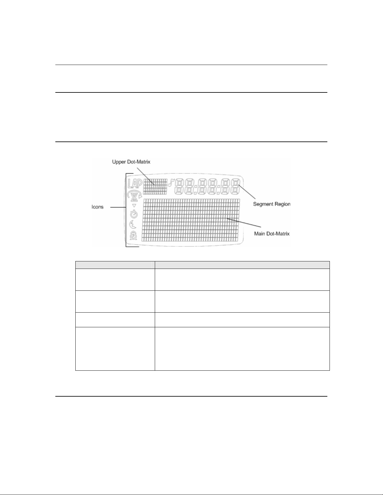
2.2 LCD
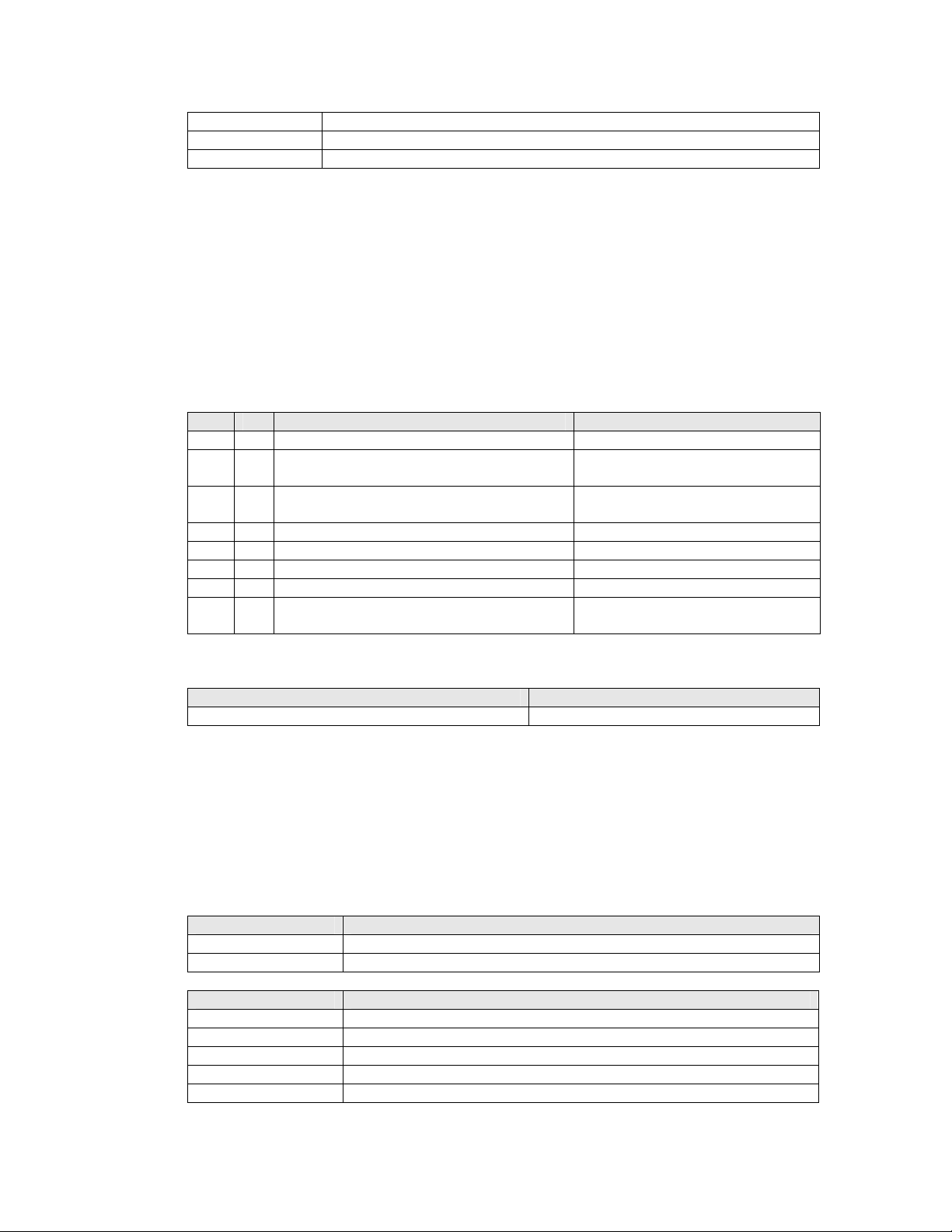
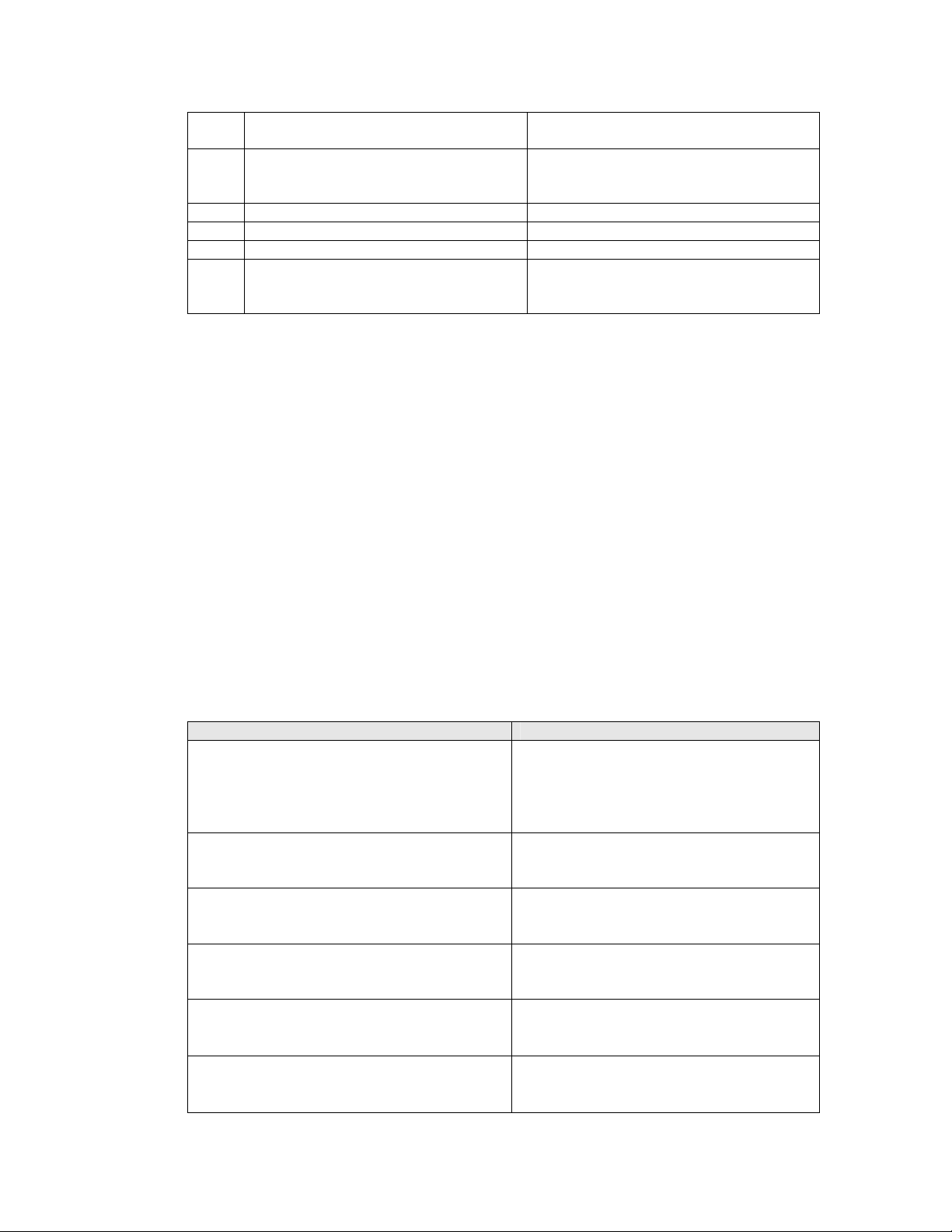
This serves as the information window of the watch. There are four regions in the viewing area:
Regions Description
Icons Unique icons (12) that can be used to shows status of system and
application.
Upper Dot-Matrix An 11 x 5 dot matrix area. Able to display 2 characters in either
fixed or proportional fonts.
Segment Regions Allows for the display of 6-digit segmented digits.
Main Dot Matrix An 42 x 11 dot matrix area. Able to display characters in either
fixed or proportional fonts, large and regular size.
Two lines are available for writing in this area when using the
regular sized fonts.
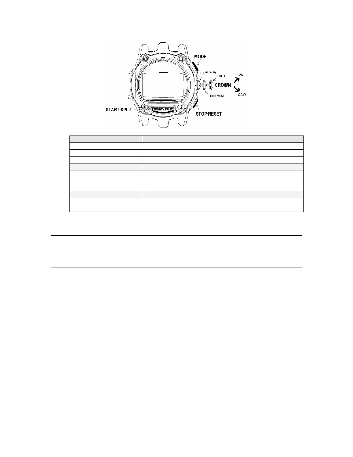
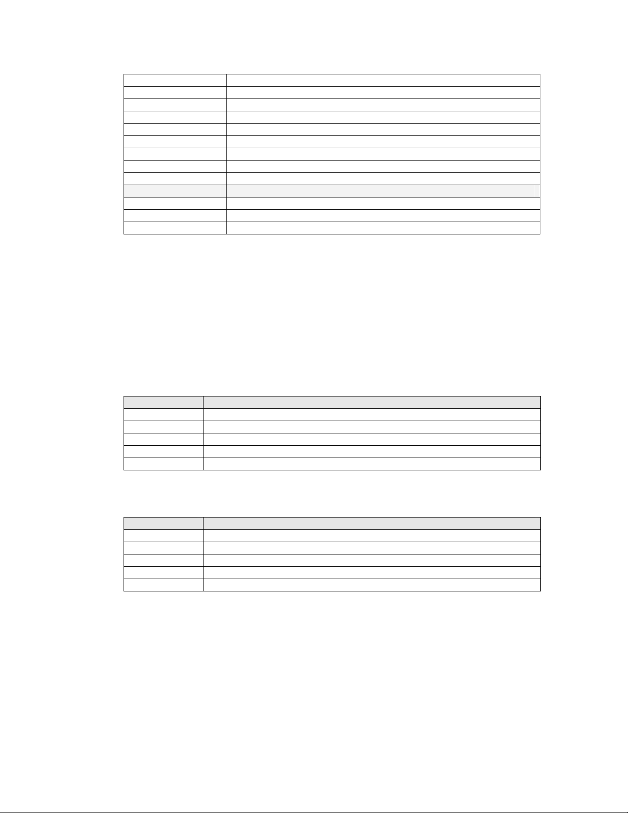
2.3 Switches
The system provides eigth switches whose functionality and use is defined by the user interface. The
kernel sends out switch activity to the foreground application through system events for processing.
Timex Corporation 2
Page 8
M851 WristApp Design Guide Rev 1.2
Switch Name Switch Type
START/SPLIT Momentary Close
STOP/RESET Momentary Close
MODE Momentary Close
EL Momentary Close
HOME Permanent
SET1 Permanent
CW Permanent
CCW Permanent
2.4 Lamp
The display device is illuminated by an Electo-Luminescent (EL) display. The Night-mode feature is
controlled by the kernel.
2.5 Buzzer
This will convert the digital signals generated inside the microcontroller into audible tones. Through a
melody generator provided by the kernel, complex melodies can be generated following a melody structure.
2.6 USB Datalink
This includes the physical components that allows two-way communications between the watch and the
PC. The PC serves as a user interface to the watch. It coordinates and controls the information that will be
transferred to and from the watch. With the PC, the user can do the following:
• Activate or deactivate applications
• Customized mode names
• Select the order of the active applications in the mode list
• Set time and date
• Download EEPROM-based applications
• Download new databases for active applications
• Upload information stored in the watch
• Etc.
An internal application, COMMUNICATION MODE, interprets and processes all the commands being
sent from the PC. This mode is automatically enabled when an active USB cable is plugged to the watch.
Timex Corporation 3
Page 9

M851 WristApp Design Guide Rev 1.2
2.7 EEPROM
Microcontrollers have limited internal memory that can be used to store data and applications. The
EEPROM serves as a high-capacity storage device that can be used to store data or code. The
microcontroller is not capable of directly executing code stored in EEPROM. It must first be copied into
internal memory prior to any processing or execution.
Utilities are provided by the kernel to facilitate accessing data from the EEPROM.
Timex Corporation 4
Page 10

M851 WristApp Design Guide Rev 1.2
3 M851 Platform
This section provides an overview of the M851 Kernel Architecture.
3.1 Overview
The M851 Kernel is a real-time operating system that serves as a platform for executing applications in a
state machine framework. The kernel is composed of the core, hardware, display, audio, timer resource,
EEPROM manager, utilities, and communications.
Core
Hardware Drivers
Display Drivers
Audio Drivers
Timer Resource
Database Utilities
Utilities
Communications
The core module controls the operation of the entire system. It makes sure
that all hardware events are processed in a timely manner and that
applications operate in a predefined manner. The core architecture defines
how applications are structured to work within the system.
The core manages the resources that are made available to applications as
well as manage the application. The core processes hardware events, and if
required, it will pass system events corresponding to the hardware event to the
application for further (and custom) processing.
The Hardware drivers provide a layer abstraction to the actual implementation
on how to operate any hardware. The hardware macros are available for use
by the core and the applications. Some macros are to be used exclusively by
the kernel.
The Display drivers are an extension of the hardware drivers dedicated only to
display services. It is a high level driver to allow the kernel and applications
to display any data in any region on the display hardware. It provides
complex display services such as blinking and scrolling.
The Audio drivers are an extension of the hardware drivers dedicated only to
the melody generation. It is a high level driver that provides services to
generate complex melodies.
The Timer Resources handles all time keeping requirements for an
application. A resource contains both data and code to control the data.
The available resources are Time-of-Day resource, Time Zone Check
resource, Backup resource, Timer resource, Stopwatch resource, and the
Synchro resource.
The resources are executed in the background. It provides macros to
manipulate every aspect of its operation. The resource frees up the
application from having to supply code to do timing specific operations such
as keeping track of time, timer functions, and comparing time data.
Provides utilities to access (read and write) records stored in EEPROM. It
provides a number of database access operations namely: sequential, fixedsized random, variable-size random and double linked list access.
The Utilities modules provides common functions that may be used by any
applications. For example: conversions, formatting, lookup, common banner
display, pseudo-randon number generation, etc.
The Communication module consists of two modules that work together.
Timex Corporation 5
Page 11

M851 WristApp Design Guide Rev 1.2
The first module are the the low level drivers that communicates
with the serial port to receive and pre-process the data packets
received through datalink.
The second module is the communication application. This receives
the valid data packets and processes the command embedded in the
packet.
3.2 Kernel Architecture
The Kernel manages a memory area known as Heap Memory. The Heap Memory serves as a depository
for code or data that an application will use. It also allocates space used for code overlay for swapping in
EEPROM-based applications code and code for periodic tasks.
The Kernel interfaces to the application through the Application Configuration Data (ACD) and the
Application Control Block (ACB). The ACD and ACB provides the kernel with the info on how an
application is configured in the system, the location of the application data, location of the state manager
and the resource handler routines.
With this generic structure, the Kernel can process any application regardless of it being stored in internal
memory or external memory. Adding new applications to the system is facilitated by this architecture
whether the application will be added during the design time or after the microcontroller has been
permanently programmed.
Due to its dependence on heap memory, the Kernel is limited in its ability to spawn a larger number of
application in memory due to limited internal memory of the microcontroller.
Timex Corporation 6
Page 12
M851 WristApp Design Guide Rev 1.2
4 WristApp Design Guide
A WristApp is basically an EEPROM-based application. The kernel will support multiple EEPROM-based
applications that also has a fixed address for its overlay area. Applications of this type can be larger than
the maximum available heap memory. When an EEPROM based application becomes the foreground
application through a mode change, the kernel will load the banner state into the application state handler
overlay area. On the succeeding request for a state change, the kernel will load the new state handler code
into the overlay area for execution.
The overlay memory area is used by all EEPROM-based applications to store both common and state code
and has a fixed location in memory.
The ASD is located in the heap. Each EEPROM based application will have its own dedicated ASD
section in the heap.
The code space is composed of two sections: common code and the application states. The common code
has all the routines that will be called by the kernel and the application states. These routines are the:
resource handler, mode banner message (if defined in application), display routines, and utility routines.
The application states are the state handlers for each state used in the application.
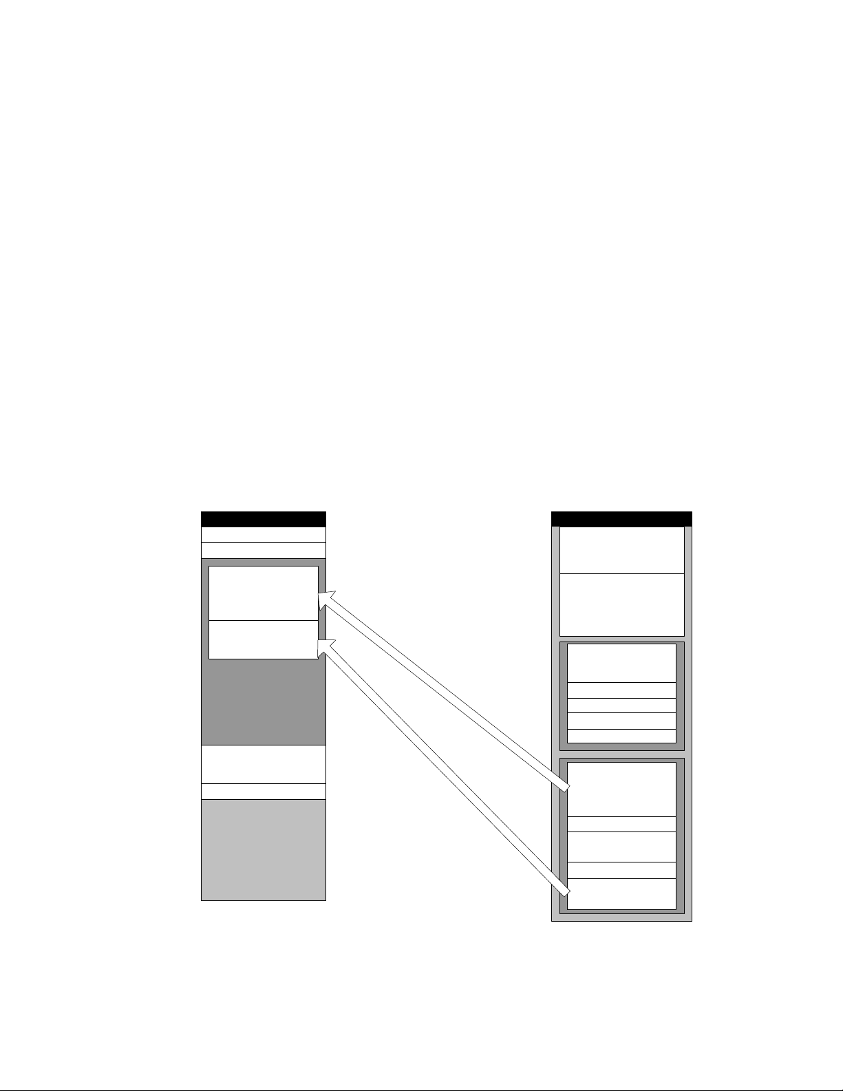
Since only one state can be in the foreground at any given time, the kernel will automatically swap in the
required state handler into the state section. This makes for efficient use of code space and allows for
larger applications to be built even with limited physical memory. The figure below shows the memory
usage of the overlay area.
HEAP
TOD ASD
COMM ASD
EEPROM APP 1
COMMON
EEPROM APP 1 STATE 3
EEPROM OVERLAY AREA
EEPROM APP 1 ASD
EEPROM APP 2 ASD
EEPROM
EEPROM APP 1 ADD
EEPROM APP 2 ADD
EEPROM APP 2
COMMON
EEPROM APP 2 STATE 0
EEPROM APP 2 STATE 1
EEPROM APP 2 STATE 2
EEPROM APP 2 STATE 3
EEPROM APP 1
COMMON
EEPROM APP 1 STATE 0
EEPROM APP 1 STATE 1
EEPROM APP 1 STATE 2
EEPROM APP 1 STATE 3
Timex Corporation 7
Page 13
M851 WristApp Design Guide Rev 1.2
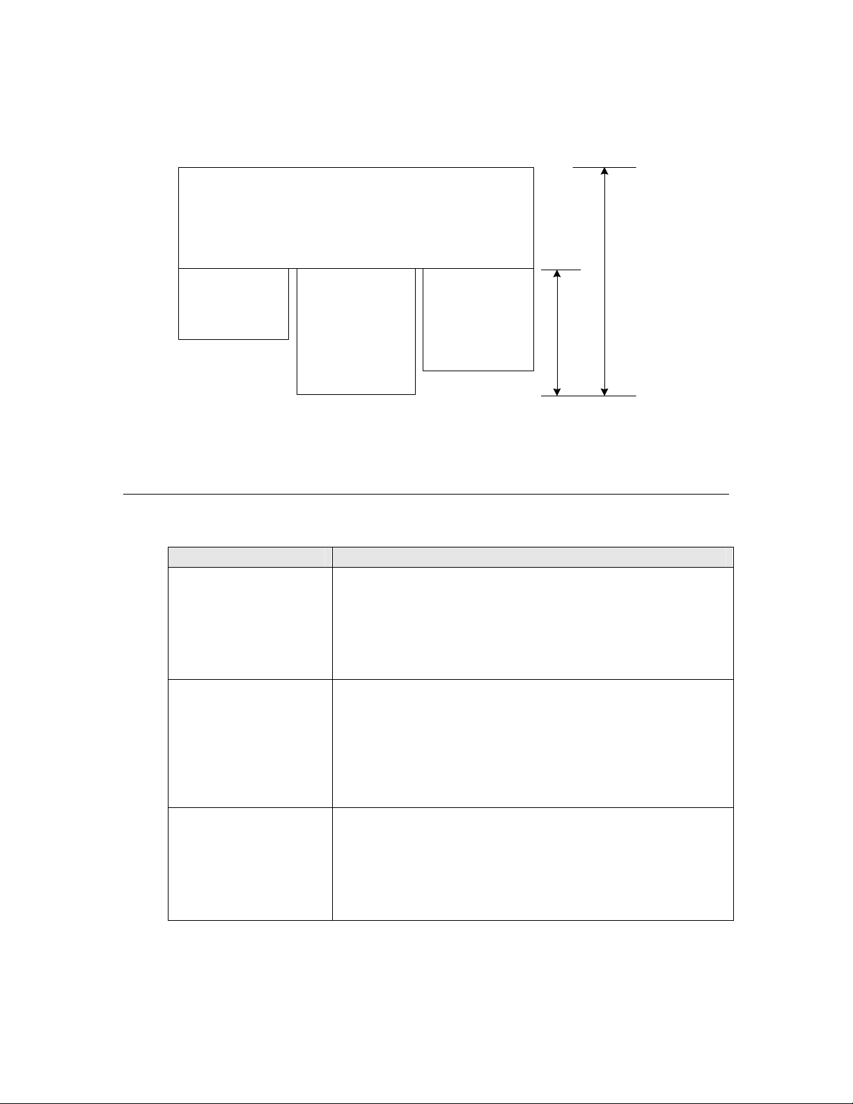
The total size requirement for an EEPROM-based application must not exceed the HEAP memory
specified by the system. The EEPROM-based application overlay usage is computed based on the sizes of
the common code and the largest state handler. The overlay size is 900 bytes.
COMMON CODE
STATE 0
STATE 1
STATE 2
STATE SECTION
APPLICATION MEMORY USAGE
4.1 Naming Conventions
A three character prefix application code will be used to distinguish application owned labels and
subroutines.
Type Usage
Constants
Variables Prefix is in upper case with mixed case for descriptive variable
Bit Variables The letter ‘B’ in lower case with the application prefix code in upper
All upper case characters.
Example:
TODNUMBEROFRESOURCE equ 2
TODSECONDSDATAOFFSET equ 0
name.
Example:
TODSecondData
TODMinuteData
case and mixed case for descriptive bit variable name.
Example:
bTODTrackingHoldToSet equ 00000001B
Timex Corporation 8
Page 14

M851 WristApp Design Guide Rev 1.2
Labels
Subroutines
Filenames MSDOS Filename convention. Eight character filename (maximum)
All in lower case characters and descriptive of its function within the
subroutine or program flow.
Example:
todchecknextevent
Prefix is all in lower case with mix case for descriptive label name.
Example:
todDefaultStateManager
todResourceRefreshHandler
with 3 character extension (maximum). ASM for source code files.
H for header files.
Example:
toddef.asm
tod.h
4.2 Files and Directories
4.2.1 Header Files
Header files are stored under the H directory of an application. They will have the extension *.H.
Generally, applications will have three header files associated with them. Namely:
General header File
Macro File
Variable File
Contains application specific equates used by an application as well
as redefinitions of system equates.
Contains macro definitions that will be used by the application.
Contains the offset definitions for variables as well as definitions for
the application system and application database heap memory
requirements. Bit definitions of application status flags are defined
in this file.
4.2.2 Source Files
Source files are stored under the SRC directory of an application. They will have the extension *.ASM.
Typical source files are for the banner state, default state, set banner state, set state, popup state,
background handler, display routines and utilities.
4.2.3 Build Directory
The build directory is where all outputs of the build scripts will be stored. This will allow the source and
header directory free from the clutter of multiple object and list files. On a successful build of a wristapp,
this directory will contain the parameter and code binary files for download to the watch.
Timex Corporation 9
Page 15
M851 WristApp Design Guide Rev 1.2
4.3 Application Setup Parameters
The kernel will use these parameters to setup an application. The application will not be initialized if the
kernel cannot allocate all the required system resources.
Application setup is done during power up for enabled ROM-based applications. During a communication
session, any application can be initialized under PC control. In both operations, the setup parameters
remain the same.
Most of the parameter settings indicated in this section (after some manipulation) will be stored in the
kernel to the Application Configuration Data and Application Control Block. Each application has its own
dedicated ACD and ACB.
4.3.1 Application Offset Mask
The Application Offset Mask specifies whether data specified in the parameter table needs to be converted
to the absolute address in heap memory. This is because the kernel will allocate available heap memory for
application system data as it is initialized in the system.
The Application Control Block addresses are all absolute memory addresses in internal memory.
This is the structure of the Application Offset Mask
Byte Bit Offset Mask Name
0 0
1
2
3
4
5 Unused
6 Unused
7 Unused
bCOREAppSystemDataOffset
bCOREAppDatabaseDataOffset
bCOREAppStateManagerOffset
bCOREAppResourceHandlerOffset
bCOREAppModeNameOffset
0 = Absolute Address
1 = Relative Address
0 = Absolute Address
1 = Relative Address
0 = Absolute Address
1 = Relative Address
0 = Absolute Address
1 = Relative Address
0 = Absolute Address
1 = Relative Address
4.3.2 Timer Resource Requirements
The application will specify the number of timer resources it would require for its operation. It will retain
ownership of the resource until it is removed from the system. When a resource is reserved, the kernel will
place the index of the resource (in order of allocation) at the start of the application system data area.
Byte Timer Resource Type Maximum
0 Time of Day Resource1 4
1 Backup 2
2 Time Zone Check Resource 5
3 Timer Resource 3
4 Stopwatch Resource 2
5 Synchro Resource 1
1
The TOD application owns three TOD resources. The kernel owns one TOD resource.
Timex Corporation 10
Page 16
M851 WristApp Design Guide Rev 1.2
The resource index always start at 0x00. For example, the TOD Resource index are 0x00, 0x01, 0x02 and
0x03. The Timer Resource index are 0x00, 0x01 and 0x02.
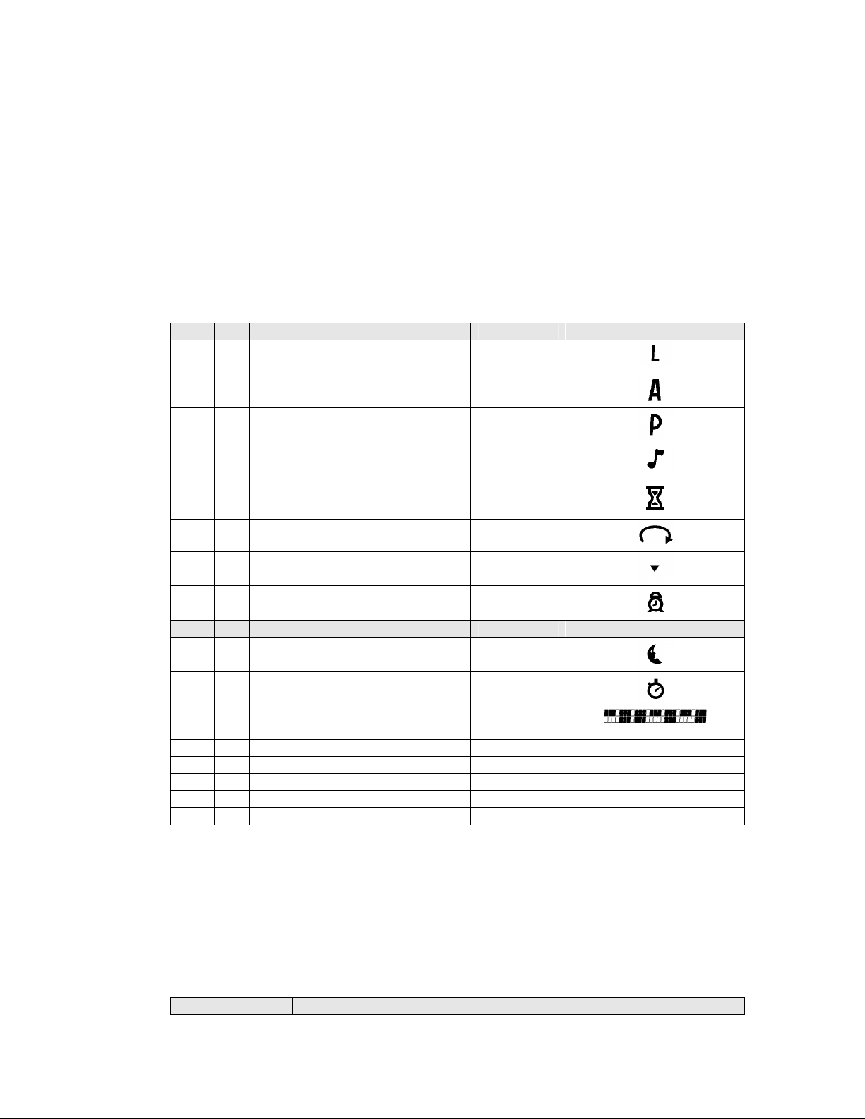
4.3.3 Icon Resource
The application will specify the LCD flags it will use to convey status information when operating in
background mode. These status flags will be visible only when the primary mode (TOD Application) is the
foreground application. For example, a timer application will use the hourglass icon to indicate that it is
running in the background.
A maximum of three applications can own and reserve an LCD icon during initialization. The kernel will
check the usage status from each of the owners to determine how to display the icon. A BLINK condition
has precedence over an ON or OFF status.
Byte Bit Icon Bit Name Icon Graphic
0 0 bCOREAppFlag_L
1 bCOREAppFlag_A
2 bCOREAppFlag_P
3 bCOREAppFlag_NOTE
4 bCOREAppFlag_HOURGLASS
5 bCOREAppFlag_RING
6 bCOREAppFlag_ARROW
7 bCOREAppFlag_ALARM
1 0 bCOREAppFlag_MOON_Flag
1 bCOREAppFlag_STP
2 bCOREAppFlag_TIMELINE_Flag
3 Unused
4 Unused
5 Unused
6 Unused
7 Unused
NOTE: When an application is in foreground mode, it has full use of all the icons and is not restricted to
the display limitations imposed by this parameter. The Timeline Icon should not be used (displayed) by the
application owner when it is currently the foreground application.
L
A
P
Note
Hourglass
Ring
Arrow
Alarm
Moon
Stopwatch
Timeline
4.3.4 Memory Requirements
The application will specify the number of bytes it requires of heap memory space. Heap memory can be
used for both data and code. An application is not initialized if the kernel does not have enough memory to
be allocated.
Word (16-bit) Heap Memory Use
Timex Corporation 11
Page 17
M851 WristApp Design Guide Rev 1.2
0 Application Code Size
1 Application System Data Size
2 Application Database Size
For EEPROM-based applications, the code size and database size define the amount of EEPROM memory
to be allocated. Application System Data size will be the amount of memory from the internal memory
heap allocated for the ASD.
Although the code size for EEPROM-based apps can be larger than the wristapp overlay area size, the
common code section and the state handler code must fit within the overlay area limitations (900 bytes).
4.3.5 Application Configuration Data
The application will specify through the Application Configuration Data how the application is going to
behave in the kernel when initialized or executed. It also provides additional information to the kernel
other system requirements.
Byte Bit Bit Name Description
0 0
1
2
3
4
5
6
7
The table below shows some predefined configuration data definitions for WristApps.
COREACDEEPROMAPP
bCOREACDReserved
bCOREACDCodeLocation
bCOREACDDatabaseDataLocation
bCOREACDCodeInvalid
bCOREACDDatabaseModified
bCOREACDInvalidDatabase
bCOREACDPasswordRequired
bCOREACDUserSpecifiedModeName
Configuration Byte Application
Restricted. Kernel Use Only.
0 = Internal Memory
1 = External Memory
0 = Internal Memory
1 = External Memory
1 = Code is invalid
1 = Database modified by user
1 = Database is invalid/not present
1 = Password required for access
1 = Mode name located in
EEPROM
CODE external. ADD external.
4.3.6 Application ID
This two-byte parameter is a unique identifier of an application. The application type is used during an
application peek operation where the kernel searches for the first matching application for peeking.
The first byte indicates the application type, while the second byte indicates an instance of that application.
By default, all ROM based application have an instance value of 0x00. If another instance of a ROM
based application is initialized, the system will increment the Instance Number by 1.
Byte Description
0 Application Type
1 Application Instance Number
Code Application Type
000H COREAPPTYPESYSTEM
002H COREAPPTYPEOPTION
011H COREAPPTYPEDATE
020H COREAPPTYPECHRONO
021H COREAPPTYPETIMER
Timex Corporation 12
Page 18
M851 WristApp Design Guide Rev 1.2
022H COREAPPTYPESYNCHROTIMER
023H COREAPPTYPECOUNTER
040H COREAPPTYPECONTACT
050H COREAPPTYPETASK
060H COREAPPTYPENOTES
070H COREAPPTYPESCHEDULE
080H COREAPPTYPETIDE
090H COREAPPTYPEDEMO
0A0H COREAPPTYPEGAME
0E0H COREAPPTYPEALARM
0E1H COREAPPTYPEAPPOINTMENT
0E2H COREAPPTYPEOCCASION
Application types above index 0xDF are considered to be applications that is dependent upon the primary
time zone settings. This will allow the background handler of these application to be called with the event
COREEVENT_PRIMARY_TIME_CHANGE whenever the primary time zone data changes.
NOTE: The instance number may be different than the value specified in this parameter table if
downloaded through a PIM.
4.3.7 Address Control Block
The kernel uses these parameters to locate the start address of both data and code used during application
execution. With the data in the Application Offset Mask, the kernel will convert the offset parameters into
absolute memory addresses.
Word (16-bit) Description
0 System Data Address/Offset
1 Database Data Address/Offset
2 State Manager Address/Offset
3 Resource Handler Address/Offset
4 Application Banner Name Address/Offset
The WristApp build script provides equates to plug into offset 2 and 3 of the Address Control Block. So
use the following below:
Word (16-bit) Description
0 System Data Address/Offset
1 Database Data Address/Offset
2
3
4 Application Banner Name Address/Offset
NOTE: The string data array referenced by the Application Banner Name must follow the Application
Banner Message Format.
CODESTATEADDRESS
CODECOMMONADDRESS
4.3.8 Sample Application Parameter Template
The following is a sample application parameter template for a WristApp.
Timex Corporation 13
;============================================================
; ACB offset mask.
;============================================================
Page 19

M851 WristApp Design Guide Rev 1.2
; Application System Data is located in heap.
; Other ACB entries are located either in ROM or EEPROM.
db bCOREAppSystemDataOffset
;============================================================
; Number of resources required.
;============================================================
db 00h ; TOD
db 00h ; Backup
db 00h ; Time Zone Check
db 00h ; Timer Resource
db 00h ; Stopwatch Resource
db 00h ; Synchro Timer Resource
;============================================================
; Flag(s) ownership.
;============================================================
db 0 ; LCD Flags 1
db 0 ; LCD Flags 2
;============================================================
; Heap size requirements.
;============================================================
dw 0280H ; Code
dw CNTSYSTEMDATASIZE ; ASD
dw CNTDATABASEDATASIZE ; ADD
;============================================================
; Application Configuration Data Byte.
;============================================================
db COREACDEEPROMAPP ; Code is external.
;============================================================
; Application Unique ID.
;============================================================
db COREAPPTYPECOUNTER ; Application type
db 01h ; Application instance number
;============================================================
; ACB Parameters.
;============================================================
dw CNTSYSTEMDATASTARTOFFSET ; ASD address offset.
dw CNTDATABASESTARTOFFSET ; ADD address offset.
dw CODESTATEADDRESS ; App state manager address
dw CODECOMMONADDRESS ; App background handler address
dw lcdBannerMsg_COUNTER ; App mode name function address
4.3.9 Application Initialization
A WristApp is initialized for the first time when the current communication session is completed. The
WristApp’s background handler is processed with the system event COREEVENT_INIT. This will allow
the WristApp to setup the required parameters in the ASD section. It could also use this time to update
ASD information from the database header info if available.
Timex Corporation 14
Page 20
M851 WristApp Design Guide Rev 1.2
4.4 Application State Handlers
4.4.1 Application Framework
The application is based on the state machine concept. Only one state is active at one time and processes
all the external events. When a state becomes active, it will first initialize all required data and status prior
to receiving and processing external events.
The M851 Kernel provides the mechanism to implement the state machine architecture. The applications
are basically made up of a number of states, where each state handles a specific function of an application.
For example, there is always a banner state, default state, a set state and a popup state.
The Kernel will only know the address of the Application State Manager located in the Application Control
Block. The State Manager will use the system variable CORECurrentState to determine the actual state
handler to execute.
For EEPROM based application, only one state handler is located in the overlay area in heap. There is no
need to have a state manager. The entry in the Application Control block will be the address of the state
handler.
4.4.2 State Transition Diagram
The State Transition Diagram (STD) facilitates the creation of an application in a state machine framework.
The STD shows in a graphic format the available application states, the events the state will be processing
and the associated action and state transitions resulting from the event being processed. With the STD, the
application can be analyzed at this stage for commonality and optimization. Once the STD is complete and
optimized, it becomes the template in coding the state handlers.
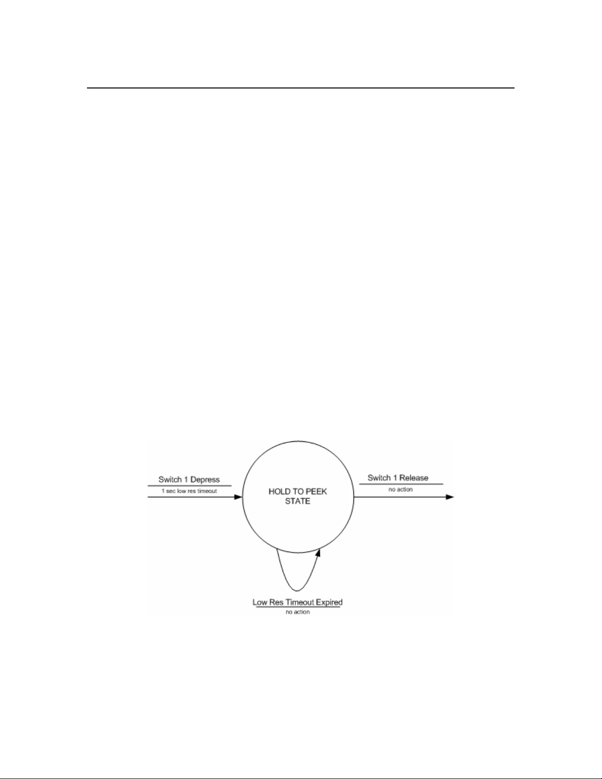
4.4.2.1 A State Transition Diagram
The state is represented as a circle. The name of the state describes the general function of the state. The
lines and arrows indicate the events that have occurred and the action to be taken.
4.4.2.2 Application State Transition Diagram
The diagram below shows the state transition diagram for an entire application. This diagram shows the
relationships and interaction between states.
Timex Corporation 15
Page 21

M851 WristApp Design Guide Rev 1.2
4.4.2.3 Implementing The Application State Transition Diagram
The State Transition Diagram will serve as a guide to develop the application template for all the state
handlers. With the template ready, the actual code to implement the function can be added to the
appropriate sections.
Guidelines in the implementation:
• The arrows pointing from a state indicates the events that occurred while in the state is active.
This will be processed inside a state.
• The arrow pointing into a state from another state will be processed in the new state as a state
entry event.
• The actions are initialized inside the state handler when the event is processed.
The code template below shows the actual code to implement the application state transition diagram
shown in the previous section. The macro code shown below are not the actual macros used in the M851
Kernel, but are used here for purposes of facilitating explanation of the operation of the code. The code
below uses C syntax for discussion purposes only.
// ;;;;;;;;;;;;;;;;;;;;;;;;;;;;;;;;;;;
// ; DEFAULT STATE HANDLER
// ;;;;;;;;;;;;;;;;;;;;;;;;;;;;;;;;;;;
AppDefaultStateManager()
{
switch(CORECurrentEvent)
{
case STATEENTRY:
// ;;;;;;;;;;;;;;;;;;;;;;;;;;;;;;;;;;;
// ; STATE ENTRY PROCESSING
// ;;;;;;;;;;;;;;;;;;;;;;;;;;;;;;;;;;;
//
Timex Corporation 16
Page 22

M851 WristApp Design Guide Rev 1.2
// insert State Entry Processing Here
//
break;
case SET1DEP:
// ;;;;;;;;;;;;;;;;;;;;;;;;;;;;;;;;;;;
// ; SET 1 DEPRESS PROCESSING
// ;;;;;;;;;;;;;;;;;;;;;;;;;;;;;;;;;;;
Breg = SET1BANNERSTATE;
CORE_REQ_STATE_CHANGE;
break;
case MODEDEP:
// ;;;;;;;;;;;;;;;;;;;;;;;;;;;;;;;;;;;
// ; NEXT MODE PROCESSING
// ;;;;;;;;;;;;;;;;;;;;;;;;;;;;;;;;;;;
CORE_REQ_NEXT_MODE_CHANGE;
break;
}
}
// ;;;;;;;;;;;;;;;;;;;;;;;;;;;;;;;;;;;
// ; SET 1 BANNER STATE HANDLER
// ;;;;;;;;;;;;;;;;;;;;;;;;;;;;;;;;;;;
AppSet1BannerStateManager()
{
switch(CORECurrentEvent)
{
case STATEENTRY:
// ;;;;;;;;;;;;;;;;;;;;;;;;;;;;;;;;;;;
// ; STATE ENTRY PROCESSING
// ;;;;;;;;;;;;;;;;;;;;;;;;;;;;;;;;;;;
//
// insert State Entry Processing Here
//
CORE_REQ_TIMEOUT_2SEC;
break;
case HOMEDEP:
// ;;;;;;;;;;;;;;;;;;;;;;;;;;;;;;;;;;;
// ; HOME DEPRESS PROCESSING
// ;;;;;;;;;;;;;;;;;;;;;;;;;;;;;;;;;;;
Breg = DEFAULTSTATE;
CORE_REQ_STATE_CHANGE;
break;
case TIMEOUTDONE:
// ;;;;;;;;;;;;;;;;;;;;;;;;;;;;;;;;;;;
// ; TIMEOUT DONE PROCESSING
// ;;;;;;;;;;;;;;;;;;;;;;;;;;;;;;;;;;;
Breg = SETSTATE;
CORE_REQ_STATE_CHANGE;
break;
}
}
Timex Corporation 17
Page 23
M851 WristApp Design Guide Rev 1.2
// ;;;;;;;;;;;;;;;;;;;;;;;;;;;;;;;;;;;
// ; SET STATE HANDLER
// ;;;;;;;;;;;;;;;;;;;;;;;;;;;;;;;;;;;
AppSetStateManager()
{
switch(CORECurrentEvent)
{
case STATEENTRY:
// ;;;;;;;;;;;;;;;;;;;;;;;;;;;;;;;;;;;
// ; STATE ENTRY PROCESSING
// ;;;;;;;;;;;;;;;;;;;;;;;;;;;;;;;;;;;
//
// insert State Entry Processing Here
//
break;
case HOMEDEP:
// ;;;;;;;;;;;;;;;;;;;;;;;;;;;;;;;;;;;
// ; HOME DEPRESS PROCESSING
// ;;;;;;;;;;;;;;;;;;;;;;;;;;;;;;;;;;;
Breg = DEFAULTSTATE;
CORE_REQ_STATE_CHANGE;
break;
case CWPULSE:
// ;;;;;;;;;;;;;;;;;;;;;;;;;;;;;;;;;;;
// ; CW PULSE PROCESSING
// ;;;;;;;;;;;;;;;;;;;;;;;;;;;;;;;;;;;
//
// Insert CW Pulse Setting Here
//
break;
case CCWPULSE:
// ;;;;;;;;;;;;;;;;;;;;;;;;;;;;;;;;;;;
// ; CCW PULSE PROCESSING
// ;;;;;;;;;;;;;;;;;;;;;;;;;;;;;;;;;;;
//
// Insert CCW Pulse Setting Here
//
break;
}
}
4.4.3 State Index
The application can have a maximum of 256 states. The first six states are predefined for common
operation among applications. The predefined states are shown in the table below.
Index Kernel Definition Description
0x00 COREBANNERSTATE The state to proceed on a mode entry.
0x01 COREDEFAULTSTATE The state to proceed to after a mode banner
state and for any mode change requests that
bypasses the mode banner state.
0x02 CORESET1BANNERSTATE Using the common crown handler, this is
the state that will be active when the crown
is placed in the SET 1 position.
Timex Corporation 18
Page 24
M851 WristApp Design Guide Rev 1.2
0x03 CORESET1STATE Handles the application SET 1 processing.
0x04 COREPOPUPSTATE The state to proceed on an application
popup request through the kernel.
0x05 COREPASSWORDDEFAULTSTATE Password entry default state handler
0x06 COREPASSWORDSETBANNERSTATE Password entry set banner state handler
0x07 COREPASSWORDSETSTATE Password entry set state handler
0x08
0xFF
USER INTERFACE NOTES:
• When in the CORESET1BANNERSTATE, the application must request for a banner timeout
prior to changing state to CORESET1STATE.
APPLICATION NOTE:
• If the application does not support a popup state, the state index COREPOPUPSTATE can be used
as a general purpose state index. Same rule follows for COREPASSWORDDEFAULTSTATE,
COREPASSWORDSETBANNERSTATE and COREPASSWORDSETSTATE. This prevents
skipping of unused state indexes.
• To support password protection, then the following indexes:
COREPASSWORDDEFAULTSTATE, COREPASSWORDSETBANNERSTATE and
COREPASSWORDSETSTATE should be used for common password entry and verification
utility.
General Purpose State Index These states have no kernel restrictions on
…
its usage.
4.4.4 System Events
When the user depresses a switch, or a requested timeout has expired, or a state change was requested, the
kernel will send these events to the foreground state of an application for processing. The following system
events are defined:
System Event Description
COREEVENT_STATEENTRY
COREEVENT_TIMEOUTDONE_LOWRES
COREEVENT_TIMEOUTDONE_HIGHRES
COREEVENT_STICKY_TIMEOUTDONE
COREEVENT_CROWN_EL_DEPRESS
COREEVENT_CROWN_EL_RELEASE
• Used to initialize a state when it becomes
the foreground state.
• Passed always on a mode or state change to
the new state handler.
• When a requested low resolution timeout
expires
• When a requested high resolution timeout
expires
• When a sticky timeout conditions are
completed.
• Passed when the crown is depressed
• Used exclusively for EL control
• Passed when the depressed crown is
released.
• Used exclusively for EL control.
Timex Corporation 19
Page 25

M851 WristApp Design Guide Rev 1.2
COREEVENT_CROWN_HOME
COREEVENT_CROWN_SET1
COREEVENT_CW_PULSES
COREEVENT_CCW_PULSES
COREEVENT_CW_EDGE_TRAILING
COREEVENT_CW_EDGE_LEADING
COREEVENT_CCW_EDGE_TRAILING
COREEVENT_CCW_EDGE_LEADING
COREEVENT_MODEDEPRESS
COREEVENT_STOPRESETDEPRESS
COREEVENT_STARTSPLITDEPRESS
COREEVENT_MODERELEASE
COREEVENT_STOPRESETRELEASE
COREEVENT_STARTSPLITRELEASE
COREEVENT_POPUPCANCEL
• Passed when the crown returns to the
HOME position from any SET position.
• Passed when the crown is placed in the
SET 1 position.
• Sent to the application every 125ms when
a CW transition of the crown is detected
within the 125ms sample window.
• Used when the application places the
system in pulse mode.
• The variable COREEventArgument stores
the number of pulses detected within the
sample window.
• Sent to the application every 125ms when
a CCW transition of the crown is detected
within the 125ms sample window.
• Used only when the application places the
system in pulse mode.
• The variable COREEventArgument stores
the number of pulses detected within the
sample window.
• Sent to the application on a trailing/leading
edge transition of the crown in the
clockwise direction.
• Used only when the system is not in pulse
mode.
• The application must use only the
TRAILING events when in edge mode.
This is where the iControl hardware makes
a cliking sound.
• Sent to the application on a trailing/leading
edge transition of the crown in the counterclockwise direction.
• Used only when the system is not in pulse
mode.
• The application must use only the
TRAILING events when in edge mode.
This is where the iControl hardware makes
a cliking sound.
• Switch depression was detected.
• Switch releases was detected.
• Sent to the application if any switch events
was detected during melody generation
phase of a popup. The event that cancelled
the melody is stored in
Timex Corporation 20
Page 26

M851 WristApp Design Guide Rev 1.2
COREEventArgument.
• The current popup melody is cancelled.
COREEVENT_DISPLAY_UPDATE_TODRES
COREEVENT_DISPLAY_UPDATE_TMRRES
COREEVENT_DISPLAY_UPDATE_STPRES
COREEVENT_DISPLAY_UPDATE_SYNCRES
COREEVENT_MELODY_DONE
COREEVENT_END_OF_SCROLLING_MESS
COREEVENT_ICON_REFRESH
COREEVENT_EVENTGENERATION
• Sent to the application to indicate that a
TOD resource (whose display update
request bit was set) has been updated.
• The event is sent directly by the timer
resource when it updates it data set.
• The application must specifically request
the resource to send the update event.
• Sent to the application to indicate that a
TIMER resource (whose display update
request bit was set) has been updated.
• The event is sent directly by the timer
resource when it updates it data set.
• The application must specifically request
the resource to send the update event.
• Sent to the application to indicate that a
STOPWATCH resource (whose display
update request bit was set) has been
updated.
• The event is sent directly by the timer
resource when it updates it data set.
• The application must specifically request
the resource to send the update event.
• Sent to the application to indicate that a
SYNCHRO resource (whose display
update request bit was set) has been
updated.
• The event is sent directly by the timer
resource when it updates it data set.
• The application must specifically request
the resource to send the update event.
• Sent to the application when the melody
generator completes the requested melody.
• The application must specify that a melody
done event is to sent after completion of
the melody.
• Sent to the application when the scrolling
has reached sentinel character.
• The application must request that the event
be sent after completion of the scroll.
• Scrolling is stopped.
• Sent to the application when any LCD
icons for the primary mode is updated.
• The application must request for these
events.
• Sent to the application when a resource
Timex Corporation 21
Page 27

M851 WristApp Design Guide Rev 1.2
(previously setup for event generation) has
detected a resource specific event
condition.
COREEVENT_COMMDATAPACKETREADY
COREEVENT_COMMFIRSTBYTERECEIVED
COREEVENT_COMMDISCONNECTED
• Sent to the comm application when a
datalink packet has been completely
received by the system
• Sent to the comm application when the
first byte of the datalink packet has been
received by the system.
• Sent to the comm application when the
USB cable has been disconnected.
4.4.5 Requesting System Events
Certain system events are passed to the application for processing only when it is requested by the
application that these events be passed.
4.4.5.1 Switch Depressions
Switch depressions are passed to the applications only when the keymask for the switch has been enabled.
It is advisable to allow only the switches that is used by the current state handler to prevent the switch event
to be passed to the application and thus canceling all blinking, scrolling and timeouts.
The three macros to setup switch depress events are shown below:
CORE_ALLOW_KEYS
CORE_MASK_KEYS
CORE_ALLOW_ALL_KEYMASK
The keymask bits are defined below:
bCOREModeSwitch
bCOREStopResetSwitch
bCOREStartSplitSwitch
bCORECWSwitch
bCORECCWSwitch
bCOREELSwitch
To allow only the mode and the stop/reset switch to be passed to the application, use the following code:
CORE_ALLOW_KEYS (bCOREModeSwitch|bCOREStopResetSwitch);
When using the macro CORE_ALLOW_KEYS, take note to specify the bit mask bCOREModeSwitch in
the default state to allow mode changes.
Using the specified keymask bits, this macro specifies the switches to be
passed as events to the application.
Using the specified keymask bits, this macro specifies which switches
are to be removed from the existing mask.
This allows all switches to be passed to the application.
Timex Corporation 22
Page 28

M851 WristApp Design Guide Rev 1.2
4.4.5.2 Switch Releases
Switch Release events are only passed to the application if a switch depression was done previously. It is
advisable to suspend switch releases if the application does not handle them in the current state handler to
prevent an unused release event to be passed to the application killing any current blinking, scrolling or
active timeouts.
The application can cancel the release event of the current depressed switch by calling the macro:
HW_KBD_CANCEL_CURRENT_SWITCH_RELEASE;
If an application does not want to handle any switch release events in the current handler, then the macro
below should be used.
CORE_SUSPEND_SWITCH_RELEASE;
To re-enable switch releases to be passed as events again, then the macro below should be called.
CORE_ENABLE_SWITCH_RELEASE;
4.4.5.3 Popup Cancel Event
If a popup state handler generates a melody, the UI specifies that any switch depression will cancel the
melody and proceed with processing. The application can define all switch cases to handle killing the
melody.
The application can make use of the macro shown below. This macro will trap the “allowed” switch
depress events and crown events and wrap it all in one core system event COREEVENT_POPUPCANCEL.
The trapped switches are now stored in COREEventArgument. This will also cancel the currently active
melody.
CORE_REQUEST_MELODY_POPUPCANCEL;
The “allowed” switch depress events mentioned above indicates the switch events that matches the key
mask on the foregroundstate handler. By default, EL switch depression are not passed as an event to the
application. The UI might specify that the EL also cancel a popup. It is required that popup state handlers
that requires the EL to cancel the popup must call the macro CORE_ALLOW_ALL_KEYMASK to have the EL
depress events be processed. When the popup has processed the popup cancel event, it can restore or
specify a new keymask.
4.4.5.4 Ring Edges and Pulses
Ring Trailing Edges are ring events passed to the application by default. Ring Leading Edge Events are
suspended by default.
To request ring pulse events to be passed to the application, the macro below should be called:
CORE_ENABLE_PULSE_MODE;
To request ring edge events again, the macro below should be used:
CORE_DISABLE_PULSE_MODE;
To suspend all ring types of ring edge events, the macro below should be used:
CORE_SUSPEND_RING_EVENTS;
Timex Corporation 23
Page 29

M851 WristApp Design Guide Rev 1.2
4.4.5.5 Icon Refresh
Certain application requires that it be called whenever changes are being done to the status of the primary
mode icons. These applications may be the TOD and the Options Mode. The TOD application requires an
icon refresh event whenever the user manually enables/disables NightMode or the system automatically
enables/disables Nightmode so it can update the MOON icon. The Options mode requires the update of the
NightMode or the Chime whenever the system changes the current status so it can display the appropriate
message. In the option mode, the event was used to update the message along with the icon depending on
the UI requirement.
To enable or disable receiving the event COREEVENT_ICON_REFRESH, then the macros below should be
called:
CORE_BACKGROUND_ICON_REFRESH_ENABLE;
CORE_BACKGROUND_ICON_REFRESH_DISABLE;
4.4.5.6 End of Scrolling
The application can request an event everytime a message that is scrolling reaches the end of the message.
The macro is below to send the “end of scrolling” event to the application. This will also stop scrolling the
message once it reaches the end of the message. If the size of the message does not require scrolling, then
the event COREEVENT_END_OF_SCROLLING_MESS is sent after the message is displayed on the LCD.
LCD_SCROLL_RAM_OR_ROM_MSG_MAIN_DM_LINE2 EVENT_ON;
If the application want the message to scroll continuosly, then the macro below is used:
LCD_SCROLL_RAM_OR_ROM_MSG_MAIN_DM_LINE2 EVENT_OFF;
4.4.5.7 Resource Updates
By default, on any state change, resource display updates are disabled by the core. To have resource
display updates event passed to the application, the application must make an API call to the resource to
request for updates. These events can then be used to display the new or updated data.
An application may request different types of resource to send the update events. Each resource type will
send a unique system event. To request (and cancel) a resource update, use the followingAPIs:
KTOD_ENABLE_DISP_UPD_SEC_EVENT
KTOD_DISABLE_DISP_UPD_SEC_EVENT
KSTP_ENABLE_DISP_UPD_EVENT
KSTP_DISABLE_DISP_UPD_EVENT
KTMR_ENABLE_DISP_UPD_EVENT
KTMR_DISABLE_DISP_UPD_EVENT
KSYN_ENABLE_DISP_UPD_EVENT
KSYN_DISABLE_DISP_UPD_EVENT
4.4.5.8 Timeouts
Application must request application timeouts for the system to generate the timeout done events. The
events are passed when the timeout counters decrements to zero.
CORE_REQ_TIMEOUT_HIRES <timeout_count_hires>;
CORE_REQ_TIMEOUT_LORES <timeout_count_lores>;
Timex Corporation 24
Page 30

M851 WristApp Design Guide Rev 1.2
CORE_REQ_TIMEOUT_STICKY <timeout_count_hires >;
The parameter timeout_count_lores is specified in seconds. The following equates are available for
timeout_count_lores:
Equate Description
TIMEOUTLORES_2SEC
TIMEOUTLORES_3SEC
TIMEOUTLORES_4SEC
TIMEOUTLORES_10SEC
TIMEOUTLORES_20SEC
2 seconds
3 seconds
4 seconds
10 seconds
20 seconds
The parameter timeout_count_hires is specified in increments of 0.125 seconds. The following equates are
available for timeout_count_hires:
Equate Description
TIMEOUTHIRES_P250SEC
TIMEOUTHIRES_P5SEC
TIMEOUTHIRES_1SEC
TIMEOUTHIRES_1P5SEC
TIMEOUTHIRES_2SEC
TIMEOUTHIRES_3SEC
TIMEOUTHIRES_4SEC
TIMEOUTHIRES_5SEC
TIMEOUTHIRES_6SEC
0.250 seconds
0.500 seconds
1 second
1.500 seconds
2 seconds
3 seconds
4 seconds
5 seconds
6 seconds
4.4.6 State Manager
There is no need for a state manager for EEPROM based applications. This is because the kernel will only
load the foreground state handler and into the same base address in the overlay area. The State Manager
address specified in the application control block will store the base address for state handler.
4.4.6.1 Display Clearing On State Change
Using the macro CORE_REQ_STATE_CHANGE to request a state change, the lcd display is always cleared.
To prevent the display from being cleared during a state change, then the macro
CORE_REQ_STATE_CHANGE_NO_CLEAR_DISPLAY should be used.
4.4.7 Mode Banner State Handler
The core will always make the mode banner the state to proceed on a mode change.
It is advised that the mode banner state define a popdown state usually the default state. This prevents a
popup from occurring in the middle of the banner timeout from returning to the banner state. To set the
popdown state, the following code is used:
It is advised that the mode banner utilize the following code to display the mode banner message. This will
allow the user through the PC to change the mode banner name.
// set popdown state should a popup occur during mode banner timeout
CORE_SET_POPDOWN_STATE OPTDEFAULTSTATE;
// display the mode banner for the application
AReg = CORECurrentMode;
CORE_CALL_MODE_NAME;
Timex Corporation 25
Page 31

M851 WristApp Design Guide Rev 1.2
By default, mode banner will request for a 1.5 second high resolution timeout before requesting a state
change to the default state. Switch depressions will cancel the mode banner timeout. Crown Set event will
not only cancel the mode banner timeout, but will proceed to the SET Banner State.
If the application supports password protection, then mode banner timeout event should make the password
state handler the foreground state. This will require the user to enter a 2-character password, verified by
the system before making the default state the foreground application.
If a password is currently required, it is advised that the banner state suspend popups. This will prevent a
popup from occurring during mode banner timeout and directly going to default state. Another method is
to make the password state the popdown state if a password is required. So on a popdown, the password
state becomes the foreground state.
Sample banner state handler:
optBannerStateManager()
{
switch( CORECurrentEvent )
{
case COREEVENT_STATEENTRY:
// ;;;;;;;;;;;;;;;;;;;;;;;;;;;;;;;;;;;;;;;;;;;;;;;;;
// ; MODE BANNER ENTRY
// ;;;;;;;;;;;;;;;;;;;;;;;;;;;;;;;;;;;;;;;;;;;;;;;;;
// set popdown state if a popup occurs during timeout
CORE_SET_POPDOWN_STATE OPTDEFAULTSTATE;
// display the mode banner for the application
AReg = CORECurrentMode;
CORE_CALL_MODE_NAME;
// request for a 1.5 second timeout banner
CORE_REQ_TIMEOUT_HIRES TIMEOUTHIRES_1P5SEC;
break;
case OPTEVENT_STOPRESETDEPRESS:
case OPTEVENT_STARTSPLITDEPRESS:
case COREEVENT_CW_EDGE_TRAILING:
case COREEVENT_CCW_EDGE_TRAILING:
case COREEVENT_TIMEOUTDONE_HIGHRES:
// ;;;;;;;;;;;;;;;;;;;;;;;;;;;;;;;;;;;;;;;;;;;;;;;;;
// ; CANCEL MODE BANNER TIMEOUT EVENTS
// ;;;;;;;;;;;;;;;;;;;;;;;;;;;;;;;;;;;;;;;;;;;;;;;;;
// Request for a state change to set state
BReg = OPTDEFAULTSTATE;
CORE_REQ_STATE_CHANGE;
break;
case COREEVENT_CROWN_SET:
// ;;;;;;;;;;;;;;;;;;;;;;;;;;;;;;;;;;;;;;;;;;;;;;;;;
// ; CROWN SET EVENT PROCESSING
// ;;;;;;;;;;;;;;;;;;;;;;;;;;;;;;;;;;;;;;;;;;;;;;;;;
// Request for a state change to set banner state
BReg = OPTSETBANNERSTATE;
CORE_REQ_STATE_CHANGE;
break;
case OPTEVENT_MODEDEPRESS:
// ;;;;;;;;;;;;;;;;;;;;;;;;;;;;;;;;;;;;;;;;;;;;;;;;;
// ; MODE SWITCH DEPRESS PROCESSING
// ;;;;;;;;;;;;;;;;;;;;;;;;;;;;;;;;;;;;;;;;;;;;;;;;;
Timex Corporation 26
Page 32

M851 WristApp Design Guide Rev 1.2
// Request for a mode change to the next mode
// or peek at primary time zone
CORE_REQ_MODE_CHANGE_NEXT;
break;
}
}
The kernel provides two routines that will handle the basic banner state functionality that may be required
by an application.
coreCommonBannerStateHandler
coreCommonBannerStateHandlerWithPassword
Common State Banner Handler
Common Banner State Handler with check
for password.
When the above routines are used, the banner state handler will be coded as follows:
cntwaBannerStateManager: ;**SUBROUTINE cntwaBannerStateManager
car coreCommonBannerStateHandler
ret
;**END SUBROUTINE cntwaBannerStateManager
If password protection is required for the mode, then the banner state handler will be coded as follows:
cntwaBannerStateManager: ;**SUBROUTINE cntwaBannerStateManager
car coreCommonBannerStateHandlerWithPassword
ret
;**END SUBROUTINE cntwaBannerStateManager
If the routine coreCommonBannerStateHandlerWithPassword is used, then state index 5,6, and
7 should be coded as shown below:
For state handler index 5:
cntIndex5StateManager: ;**SUBROUTINE cntIndex5StateManager
car corePasswordDefaultStateHandler
ret
;**END SUBROUTINE cntIndex5StateManager
For state handler index 6:
cntIndex6StateManager: ;**SUBROUTINE cntIndex6StateManager
car corePasswordSetBannerStateHandler
ret
;**END SUBROUTINE cntIndex6StateManager
For state handler index 7:
cntIndex7StateManager: ;**SUBROUTINE cntIndex7StateManager
car corePasswordSetStateHandler
ret
;**END SUBROUTINE cntIndex7StateManager
Timex Corporation 27
Page 33

M851 WristApp Design Guide Rev 1.2
4.4.8 Default State Handler
The default state handler controls the main function specified for an application.
4.4.9 Set Banner State Handler
The core will always make the Set banner the state to proceed when the crown is pulled to the SET
position.
It is advised that the set banner state define a popdown state usually the set state. This prevents a popup
from occurring in the middle of the banner timeout from returning to the set banner state. To set the
popdown state, the following code is used:
Sample Set Banner State Handler:
// set popdown state should a popup occur during mode banner timeout
CORE_SET_POPDOWN_STATE OPTSETSTATE;
optSetBannerStateManager()
{
switch( CORECurrentEvent )
{
case COREEVENT_STATEENTRY:
// ;;;;;;;;;;;;;;;;;;;;;;;;;;;;;;;;;;;;;;;;;;;;;;;;;
// ; SET BANNER ENTRY
// ;;;;;;;;;;;;;;;;;;;;;;;;;;;;;;;;;;;;;;;;;;;;;;;;;
// set popdown state if a popup occurs during
// set banner timeout
CORE_SET_POPDOWN_STATE OPTSETSTATE;
// clear display
LCD_CLEAR_DISPLAY;
//display 'ON/OFF TIME' for both night-mode and chime banner
LCD_DISP_SMALL_DM_MSG_ONOFF_TIME;
// request for a 1.5 second timeout banner
CORE_REQ_TIMEOUT_HIRES TIMEOUTHIRES_1P5SEC;
break;
case OPTEVENT_MODEDEPRESS:
case OPTEVENT_STOPRESETDEPRESS:
case OPTEVENT_STARTSPLITDEPRESS:
case COREEVENT_CW_EDGE_TRAILING:
case COREEVENT_CCW_EDGE_TRAILING:
case COREEVENT_TIMEOUTDONE_HIGHRES:
// ;;;;;;;;;;;;;;;;;;;;;;;;;;;;;;;;;;;;;;;;;;;;;;;;;
// ; CANCEL SET BANNER TIMEOUT EVENTS
// ;;;;;;;;;;;;;;;;;;;;;;;;;;;;;;;;;;;;;;;;;;;;;;;;;
// Request for a state change to set state
BReg = OPTSETSTATE;
CORE_REQ_STATE_CHANGE;
break;
case COREEVENT_CROWN_HOME:
// ;;;;;;;;;;;;;;;;;;;;;;;;;;;;;;;;;;;;;;;;;;;;;;;;;
// ; CROWN HOME EVENT PROCESSING
// ;;;;;;;;;;;;;;;;;;;;;;;;;;;;;;;;;;;;;;;;;;;;;;;;;
// Request for a state change to default state
BReg = OPTDEFAULTSTATE;
CORE_REQ_STATE_CHANGE;
break;
Timex Corporation 28
Page 34

M851 WristApp Design Guide Rev 1.2
}
}
4.4.10 Set State Handler
The Set State Handler defines the setting function of an application. It is advised that the handler disable
popups for the duration of the set state.
Use ring edge events if the data being set only has a few selection. Use ring pulse events to track the
number of pulses detected in a predetermines time frame.
Use the acceleration routines to convert the raw pulses detected by the system to predetermined accelerated
values. This allows for fast setting of data. Below is a sample code fragment the uses acceleration to
update data.
case COREEVENT_CW_PULSES:
// ;;;;;;;;;;;;;;;;;;;;;;;;;;;;;;;;;;;;;;;;;;;;;;;;;
// ; CW PULSE EVENT
// ;;;;;;;;;;;;;;;;;;;;;;;;;;;;;;;;;;;;;;;;;;;;;;;;;
// ;;;;;;;;;;;;;;;;;;;;;;;;;;;;;;;;;;;;;;;;;;;;;;;;;
// ; CHIME SUB-OPTION
// ;;;;;;;;;;;;;;;;;;;;;;;;;;;;;;;;;;;;;;;;;;;;;;;;;
// We will be adjusting only the hour data.
// The minute data remains at zero.
// We use the utility to convert the data in COREEventArgument
// into accelerated data. The accelerated data is stored in
// KRESMinBuffer.
UTLACCELERATION_1MIN;
AReg = KRESMinBuffer;
// point to the current hour data of the current time structure
// being displayed
HLReg = OPTTimeStructurePtr;
++HLReg;
BReg = *HLReg;
// go to decimal math operations since our data is in packed BCD.
UTL_DECIMAL_MATH_MODE;
// add the current hour with the accelerated data.
AReg += BReg;
// check if we are still within hour maximum limits. if over,
// then we should wraparound the data.
if( AReg >= OPT_MAX_HOUR )
{
AReg -= OPT_MAX_HOUR;
}
// restore default math operation mode
UTL_BINARY_MATH_MODE;
// store the new hour data into the structure
*HLReg = AReg;
// display the new data and request blinking
goto optSetDisplayRefreshTimeOnly;
Timex Corporation 29
Page 35

M851 WristApp Design Guide Rev 1.2
4.4.11 Popup State Handler
The popup state handler is executed whenever a resource requests for a popup session. The kernel will call
the interrupted application’s Task Exit handler, stores the data in CORECurrentMode and
CORECurrentState into COREPopupMode and COREPopupState. CORECurrentState is not
saved if the state handler specified a different popdown state.
When a popup is complete, it must be terminated with a popdown request using the macro below. This will
alert the kernel that a popup session is complete. The stored COREPopupMode and COREPopupState
becomes the new foreground application unless the kernel detects that there are pending popups to be
processed.
CORE_REQ_POPDOWN;
4.4.11.1 Special Time Zone Check Popup Processing
Normally, when the popup state handler has processed the record that generated the popup through the
Time Zone Check Popup, the state handler can request a popdown immediately.
There are some cases wherein there are more then one entry that matches the record that was entered into
the Time Zone Check resource for checking. Since there is only one TZC Resource allocated to an
application, there is no way to store the entries in individual TZC resources.
When the popup state handler completes processing (melody generation, melody cancellation or
completion, 4 second timeout after scrolling, etc.), it could check for its database for any other record aside
form the one already displayed. If there are no more entries, then it could then request a popdown. If there
is another entry, then the popup state handler can re-execute the code stored in state entry event processing
section to generate the new melody, etc. and proceed with processing the “new” popup.
It is up to the application on how many entries it wants to popup for the same time. The current UI
specifies only one queued popup when the current one is active.
4.4.12 Password Entry State Handler
Some applications are required to check if a password is required to access the data stored in the database.
If a password is required, it will request a state change to the application’s password entry and verification
state.
• The kernel provides a generic password entry and verfication state handler. The state handler
name is corePasswordDefaultStateHandler(),
corePasswordSetBannerStateHandler() and
corePasswordSetStateHandler().
The application is required to allocate index 5, 6 and 7 in the Application State Manager. When the
password is entered and verified, it will request a state change to the application’s default state.
During execution of password handler states, all popups are suspended.
4.5 Built-in State Handlers
The system provides a number of state handlers that a wristapp can use that are already stored in ROM.
This will speed up loading the code from EEPROM as well as minimize the total EEPROM usage of a
WristApp.
Timex Corporation 30
Page 36

M851 WristApp Design Guide Rev 1.2
These state handlers are designed to function in a predefined manner that are used by the built-in ROM
applications. They should be used as intended.
State Handler Description
coreCommonBannerStateHandler
Handles mode banner state processing.
• Displays either the default mode banner
message or the user defined mode banner
stored in EEPROM;
• Waits for 1.5 seconds prior to requesting
a state change to default state index;
• Process Mode Switch depression to
proceed to the next mode;
• Setup the popup return state to be the
default state index;
• Process the Crown_Set event to proceed
to the Set Banner State index;
• Process the other switches to bypass the
1.5 second timeout and request a state
change to the default state index.
coreCommonBannerStateHandlerWithPassword
Handles mode banner state processing.
• Displays either the default mode banner
message or the user defined mode banner
stored in EEPROM;
• Waits for 1.5 seconds prior to requesting
a state change to default state index;
• Process Mode Switch depression to
proceed to the next mode;
• Setup the popup return state to be the
default state index;
• Checks if the mode is currently setup to
request a password prior to proceeding to
the default state index;
• If Password Not Required:
o Process the Crown_Set event to proceed
to the Set Banner State index;
o Process the other switches to bypass the
1.5 second timeout and request a state
change to the default state index.
• If Password is required:
o Process Crown_set event to proceed to
the Password Set Banner state index;
o Process the other switches to bypass the
1.5 second timeout and request a state
change to the Password Default State
index.
corePasswordDefaultStateHandler
Handles the following:
• Displays the message “PASSWORD
NEEDED”;
• Process the Crown_Set event to request a
state change to the Password Set Banner
state index;
• Process the Mode switch to proceed to the
next mode;
corePasswordSetBannerStateHandler
Handles the following:
Timex Corporation 31
Page 37

M851 WristApp Design Guide Rev 1.2
• Displays the message “ENTER
PASSWORD”;
• Requests a 1.5 second banner timeout;
• On timeout expiration, request a state
change to the Password Set State index;
• Process the Crown_Home event to
request a state change to the Password
Default State index;
• Process switch events to bypass the
timeout and request a state change to the
Password Set State index;
corePasswordSetStateHandler
Handles the following:
• Handles all the events required to request
input from the user for a two character
password;
• Process the Crown_Home event to check
if the password entered is correct;
• If password is correct, request a state
change to the default state index;
• If password is incorrect, then display the
message “PASSWORD INVALID” and
request a state change to the password
default state index after a 2 second
timeout period.
utlYouRockStateManager
If a WristApp does not support a set state, then the
set banner state should use this function. It
handles the following:
• Display the message “YOU ROCK!”;
• Process the Crown_Home event to
request a state change to the default state
index.
The code section below shows how the You Rock State Manager is used in the code:
SetStateManager:
car utlYouRockStateManager
ret
The WristApp developer can choose to customize the operation of the built-in state handlers by preempting
the system event passed by the OS. The code section below shows a way to bypass the message displayed
on state entry to the utlYouRockStateManager with a custom message.
SetStateManager:
; preempt the STATE_ENTRY event for custom processing
ld A, [CORECurrentEvent]
cp A, #COREEVENT_STATEENTRY
; display customized banner message
jr NZ, process_event_in_default_handler
ld IY, #MY_CUSTOM_MESSAGE
LCD_DISP_BANNER_MSG
ret
process_event_in_default_handler:
Timex Corporation 32
Page 38

M851 WristApp Design Guide Rev 1.2
car utlYouRockStateManager
ret
MY_CUSTOM_MESSAGE:
; custom message “MY NAME”
db LCDBANNER_COL4
db DM5_M, DM5_Y
db LCDBANNER_COL2
db DM5_N, DM5_A, DM5_M, DM5_E
db LCD_END_BANNER
4.6 Timer Resource Usage
The Timer Resource allows background operation under kernel control without having the application
provide the code and data to update the required variables.
The application request ownership of specific Timer Resource for its operation only during application
initialization. The kernel will automatically reserve the specified resource and store the resource index at
the top of the application system data area. The reservation is done in this sequence: TOD, BACKUP,
TZC, TIMER, STOPWATCH, and SYNCHRO.
4.6.1 Display Update Events
Any foreground application can request display update events from any resource (except for the Backup
and Time Zone Check Resource). The events are processed by the application to show updated resource
data. The frequency of events being passed to the application is dependent upon the type of resource. Only
active resources will send out display update events to the foreground application.
Resource Type Frequency
Time of Day Resource 1 Hz
Timer Resource 8 Hz
Stopwatch Resource 16 Hz
Synchro Resouce 16 Hz
Display Update Event requests is not restricted to the owner application. Any foreground application can
request this event from a resource. When an event occurs, the kernel will send the event associated with
the resource. The following are the the different update events:
• COREEVENT_DISPLAY_UPDATE_TODRES
• COREEVENT_DISPLAY_UPDATE_TMRRES
• COREEVENT_DISPLAY_UPDATE_STPRES
• COREEVENT_DISPLAY_UPDATE_SYNRES
On a mode or state change, the kernel will cancel all display update event requests of all timer resources.
4.6.2 Popup and Event Generation
Owner applications can request popup or events to be generated to accompany any resource events that
occurred. These events vary from resource to resource. The table below shows a summary of the events.
Resource Type Resource Event
Backup Resource
• Counter that is decremented every minute until it
reaches 0.
Timex Corporation 33
Page 39

M851 WristApp Design Guide Rev 1.2
Time Zone Check Resource
• Exact Match with Reference Time.
Timer Resource
• Countdown reaches 0:00.00.
• Countup reaches specified time of resource.
• Halfway2 Count is reached (countup and
countdown).
Stopwatch Resource
• Countup data reached maximum time.
Synchro
• Countup data reached maximum time.
When an event is requested, the kernel will pass the event COREEVENT_EVENTGENERATION to the
foreground application regardless of resource ownership.
When a popup is requested, the kernel will acknowledge the request and queues the resource popup. When
the kernel completes other higher priority tasks, it will then proceed with the popup check operation. If
multiple popups are queued, the popup priority is based on the following order: TIMER, BACKUP, TIME
ZONE CHECK, TIMER and SYNCHRO.
The application owner of the resource will now become the foreground application. The current state
would be the popup state (COREPOPUPSTATE).
If the application generates a message that can be cancelled by any switch depression, the macro
CORE_REQUEST_MELODY_POPUPCANCEL must be called in the popup state handler. If a switch was
used to cancel the melody, the kernel will convert the switch event into the event
COREEVENT_POPUPCANCEL with the old switch event in COREEventArgument. The popup
application must look at the entry in the COREEventArgument so that it can process the crown set event.
After completing the operation, the application must request a popdown through the macro
CORE_REQ_POPDOWN.
APPLICATION NOTE
• Before an alarm or appointment application popup request for a popdown, it is advise that it checks all
the entries in the database that matches the current time in the popup clock and if available, restart the
popup sequence for the new entry. It is up to the application to determine how many more matching
entries to popup. Take note that the application is not requesting a new popup here from the kernel.
4.6.3 Time Of Day Resource
The Time-of-Day resource keeps track of the time (second, minute, hour, date, month, year, day of week
and week number). The resource provides a number of methods that can be used to manipulate, modify
any data or status bits of a specific resource. Refer to the M851 Application Programming Interface
Document for more details in using the TOD Resource.
TOD Resource Data Structure:
Offset Data Type Description
0 Application Index Index of application owner
1 Resource Flag Specifies status of the resource and how this data
2
Typical use of this event is to track the halfway mark of a timer count. This mark can be any number
between 0:00.00 and the countdown time.
Timex Corporation 34
Page 40

M851 WristApp Design Guide Rev 1.2
structure is displayed on the LCD.
2 Update Flag Indicates the data positions that were recently updated.
3 Second Seconds data in BCD format
4 Minute Minute data in BCD format
5 Hour Hour data in BCD format
6 Date Date data in BCD format
7 Month Month in BCD format
8 Year (Lo Byte) Year data (low byte) in BCD format
9 Year (Hi Byte) Year data (high byte) in BCD format
10 Day of Week Computed Day of Week data
11 Week Number Computed Week Number data in BCD format
Resource flag bit definitions:
Bit Name Description
bKReserved
0
bKActive
1
bKDispUpdRequest
2
bKTODPrimaryTZ
3
bKTODEuroFormat
4
bKTOD24HourFormat
5
bKTODWeekNumberDisplay
6
bKTODYMDFormat
7
Update flag bit definitions:
Bit Name Description
unused
0
bKTODMinuteUpd
1
bKTODHourUpd
2
bKTODDateUpd
3
bKTODMonthUpd
4
bKTODYearUpd
5
bKTODWeekUpd
6
Unused
7
Resource is owned
Resource is active
Display Update Event is requested
Resource is the primary time zone
Display date in Euro format
Display hour in 24-format
Display week number
Display in YMD format
Minute data is updated
Hour data is updated
Date data is updated
Month data is updated
Year data is updated
Week data is updated
4.6.4 Backup Resource
The Backup Resource provides an application the ability to track the number of minutes since the last
resource setup and activation.
This is used to track a backup alarm for an alarm application rather than wasting a Time Zone Check
Resource which is much more complex to setup.
BACKUP Resource Data Structure:
Offset Data Type Description
0 Application Index Index of application owner
1 Resource Flag Specifies status of the resource
2 Counter Specifies the number of minutes of countdown.
Resource flag bit definitions:
Bit Name Description
Timex Corporation 35
Page 41

M851 WristApp Design Guide Rev 1.2
bKReserved
0
bKActive
1
Unused
2
Unused
3
Unused
4
Unused
5
bKGeneratePopup
6
bKGenerateEvent
7
Resource is owned
Resource is active
Generate a popup when counter reaches zero.
Generate an event when counter reaches zero.
4.6.5 Time Zone Check Resource
The Time Zone Check Resource is used to check data stored in the resource against a reference time zone.
This is primarily used for applications such as the alarm and appointment types. The application is
responsible for determining the time data to store in the resource for checking.
The reference time zone discussed here is usually the primary time zone. But, if the time zone checking
has been suspended for a long period of time (set mode, multiple popups, etc.), the kernel will grab a copy
of the current primary time zone data and stores it into a popup clock resource. The popup clock resource
will now become the new reference time zone. When the watch is in a position to initiate a time zone
check, it will compare it against the reference time zone. The reference time zone is updated a minute
every second until it catches up with the primary time zone. Any matching entry will be popped up. Once
it exceeds the primary time zone data, the kernel disables the popup clock and makes the primary time zone
as the reference time zone.
The resource will generally check for an exact match between hour and minute data. The user can also
specify that the resource check for matching month, date, year or a combination of these entries.
The application must provide code in its Resource Handler to process the event COREEVENT_REFRESH to
put in the best entry in the time zone check resource. The application must use the reference timezone data.
By convention, any application that changes data in the TOD resource must request the Kernel to execute
all resource handlers with the event COREEVENT_REFRESH.
TZC Resource Data Structure:
Offset Data Type Description
0 Application Index Index of application owner
1 Resource Flag Specifies status of the resource
2 Update Flag Specifies if month, date and year data are required for
an exact match
3 Minute Minute data in BCD format
4 Hour Hour data in BCD format
5 Date Date data in BCD format
6 Month Month in BCD format
7 Year (Lo Byte) Year data (low byte) in BCD format
8 Year (Hi Byte) Year data (high byte) in BCD format
Resource flag bit definitions:
Bit Name Description
bKReserved
0
bKActive
1
Unused
2
Unused
3
Unused
4
Resource is owned
Resource is active
Timex Corporation 36
Page 42

M851 WristApp Design Guide Rev 1.2
Unused
5
bKGeneratePopup
6
bKGenerateEvent
7
Update flag bit definitions:
Bit Name Description
Unused
0
Unused
1
Unused
2
BKTZCDateUpd
3
BKTZCMonthUpd
4
bKTZCYearUpd
5
Unused
6
Unused
7
APPLICATION NOTES:
• If an application has multiple entries with the same popup time, only one entry is placed in the
resource. Once the popup occurs, the application is responsible (if required) to display all the
matching entries (like if a popup occurred) before requesting a popdown.
• Database is stored in EEPROM. Reading a number of records from EEPROM may take a long
time and a watchdog reset might occur in the middle of the operation. It is recommended that the
macro HWRESETWATCHDOG be inserted in the loop.
NOTE: Having only one entry per application makes for efficient use of processor time (and battery life)
since the application will search for the best record to put into the resource and will await until a popup
occurs to check for the next entry. So every minute, even if an application has 50 active records, the kernel
will check only one resource against the reference time zone.
Generate a popup when counter reaches zero.
Generate an event when counter reaches zero.
Date data is significant in checking for exact match
Month data is significant in checking for exact match
Year data is significant in checking for exact match
4.6.6 Timer Resource
The Timer Resource provides general timer functions to an application. This is used mainly by Timer
applications. With this resource, an application can start, stop, and reset the timer. The timer can handle
both count-down and count-up functions. With the user set data, the timer can do an automatic reload of
the user set data and start counting. With the pre-warning data, the timer can invoke a popup to indicate the
count has reach a specified time. The timer resource can be linked to start either a stopwatch resource or
another timer resource when the timer has expired.
The following tables show the data structure of the timer resource.
TIMER Resource Data Structure:
Offset Data Type Description
0 Application Index Index of application owner
1 Resource Flag Specifies status of the resource
2 Update Flag Specifies if month, date and year data are required for
an exact match
3 Previous Counter Sample
4 Work Hundredth data Running hundredths data in BCD format
5 Work Second data Running seconds data in BCD format
6 Work Minute data Running minute data in BCD format
7 Work Hour data Running hours data in BCD format
8 Linked TMR ID Index Link to TMR Resource
For resource use only
Timex Corporation 37
Page 43

M851 WristApp Design Guide Rev 1.2
9 Linked STP ID Index Link to STP Resource
10 User Second data User set seconds data in BCD format
11 User Minute data User set minute data in BCD format
12 User Hour data User set hours data in BCD format
13 Pre-warning Second data Pre-warning seconds data in BCD format
14 Pre-warning Minute data Pre- warning minute data in BCD format
15 Pre-warning Hour data Pre- warning hours data in BCD format
16 Running repeat counter data Running repeat counter
17 Preset repeat counter data Preset repeat counter
Resource flag bit definitions:
Bit Name Description
bKReserved
0
bKActive
1
bKDispUpdRequest
2
bKTMRLink
3
bKSTPLink
4
bKNotReset
5
bKGeneratePopup
6
bKGenerateEvent
7
Update flag bit definitions:
Bit Name Description
bKTMRSecondUpd
0
bKTMRMinuteUpd
1
bKTMRHourUpd
2
BKTMRPreWarningPopup
3
BKTMRPreWarningDone
4
BKTMRRepeat
5
bKTMRPreWarning
6
bKTMRDirection
7
APPLICATION NOTES:
• POPUPS AND BACKGROUND HANDLERS
Popup requests are generated when a timer countdown/up expires. Along with the popup request,
the resource will execute the application’s background handler. In due time, the kernel will
execute the application popup. This allows an application to keep on updating the timer resource
with new countdown data even if popups are currently suspended by the system. For example: a
timer application having multiple countdown data that is started in sequence. When the first
countdown data expires, the application resource handler will load the new countdown data and
starts the timer resource.
• PRE-WARNING POPUP
Resource is owned
Resource is active
Display update request
Link to a timer resource
Link to a stopwatch resource
Indicates resource is not in reset state
Popup Request for resource events
Event Request for resource events
Seconds data has been updated
Minute data has been updated
Hour data has been updated
Current popup is a pre-warning popup
Pre-warning popup has already occurred
Automatically reload user data and begin countdown
0 = no repeat
1 = repeat countdown/countup
Request for a pre-warning popup
0 = no pre-warning popup
1 = Request for a Pre-warning popup
Count direction:
0 = count down
1 = count up
Timex Corporation 38
Page 44

M851 WristApp Design Guide Rev 1.2
A pre-warning popup can be setup to indicate that the countdown has reach a predefined time. For
example, a timer application can set up a half-way alert indicator when the countdown data
reaches the half-time of the countdown. If an application is specified to generate only a beep
when it reaches a halfway mark, the kernel by default will still clear the display. The display will
flicker as the kernel switches to the popup state then back to the interrupted application. It is
advisable to generate the beep inside the resource handler rather than in the popup to prevent the
flicker.
• INVOKING A STOPWATCH RESOURCE
When a timer resource countdown data expires, it can automatically start a stopwatch resource by
using the STP Link. For example, a timer application can start a chronograph application upon
expiration. This is commonly referred to as the CDC (Count Down Chrono) operation. The
application must check for the existence of an application before setting up the links to a
stopwatch resource.
• INVOKING A TIMER RESOURCE
When a timer resource countdown data expires, it can invoke another timer resource to begin
counting by using the TMR Link. For example: a timer application can have multiple countdown
times used for an exercise routine. On expiration of the timer, it can automatically start another
timer resource that has the next set of countdown data. The application must check for the
existence of an application before setting up the links to a stopwatch resource.
• INVOKING A SYNCHRO RESOURCE
A synchro resource is automatically started if a timer resource is started from reset. The
application will not do anything to make this happen. The synchro resource now keeps track of
the application that started it. When the timer resource is stopped, the synchro stoppage timer will
automatically started. If started again, the synchro stoppage timer will stop.
If an application is using two timer resource to implement a interval timer application, the timer
application must take into consideration its effect on the synchro resource. The first timer must
have its reset status flag set, while the second timer resource will have its reset status flag cleared.
In that way, the start of the first interval time will start the synchro resource but the start of the
second interval timer resource will not restart the synchro resource.
4.6.7 Stopwatch Resource
The Stopwatch Resource provides general chronograph functions to an application. This is used mainly by
chrono applications. With this resource, an application can start, stop, and reset the chronograph. The
stopwatch resource can be linked to start either a timer resource or another stopwatch resource when the
stopwatch resource expires.
The following tables show the data structure of the stopwatch resource.
STOPWATCH Resource Data Structure:
Offset Data Type Description
0 Application Index Index of application owner
1 Resource Flag Specifies status of the resource
2 Update Flag Specifies if month, date and year data are required for
an exact match
3 Previous Counter Sample
4 Hundredth data Running hundredths data in BCD format
Timex Corporation 39
For resource use only
Page 45

M851 WristApp Design Guide Rev 1.2
5 Second data Running seconds data in BCD format
6 Minute data Running minute data in BCD format
7 Hour data Running hours data in BCD format
8 Linked TMR ID Index Link to TMR Resource
9 Linked STP ID Index Link to STP Resource
Resource flag bit definitions:
Bit Name Description
bKReserved
0
bKActive
1
bKDispUpdRequest
2
bKTMRLink
3
bKSTPLink
4
bKNotReset
5
bKGeneratePopup
6
bKGenerateEvent
7
Update flag bit definitions:
Bit Name Description
bKSTPSecondUpd
0
bKSTPMinuteUpd
1
bKSTPHourUpd
2
Unused
3
Unused
4
Unused
5
Unused
6
BKSTPRunout
7
• INVOKING A SYNCHRO RESOURCE
A synchro resource is automatically started if a stopwatch resource is started from reset. The
application will not do anything to make this happen. The synchro resource now keeps track of
the application that started it. When the stopwatch resource is stopped, the synchro stoppage timer
will automatically started. If started again, the synchro stoppage timer will stop.
Resource is owned
Resource is active
Display update request
Link to a timer resource
Link to a stopwatch resource
Indicates resource is not in reset state
Popup Request for resource events
Event Request for resource events
Seconds data has been updated
Minute data has been updated
Hour data has been updated
Indicates if stopwatch resource has run out
0 = not reached maximum time
1 = reached maximum time (100 Hours)
4.6.8 Synchro Resource
The Synchro resource is a special type of stopwatch resource that is always linked to start when a timer or
stopwatch resource is started from reset. The resource will activate its stoppage counters when the timer or
stopwatch resource that started it is stopped by the user.
The synchro resource can only be reset under application control.
If a synchro resource is currently active and a stopwatch or timer resource is started from reset, the synchro
resource is reset and started from 0:00.00.
The following tables show the data structure of the synchro resource.
SYNCHRO Resource Data Structure:
Offset Data Type Description
Timex Corporation 40
Page 46

M851 WristApp Design Guide Rev 1.2
0 Application Index Index of application owner
1 Resource Flag Specifies status of the resource
2 Update Flag Specifies if month, date and year data are required for
an exact match
3 Previous Counter Sample
4 Hundredth data Running hundredths data in BCD format
5 Second data Running seconds data in BCD format
6 Minute data Running minute data in BCD format
7 Hour data Running hours data in BCD format
8 Linked TMR ID Index Link to TMR Resource
9 Linked STP ID Index Link to STP Resource
Resource flag bit definitions:
Bit Name Description
bKReserved
0
bKActive
1
bKDispUpdRequest
2
bKTMRLink
3
bKSTPLink
4
bKNotReset
5
bKGeneratePopup
6
bKGenerateEvent
7
Update flag bit definitions:
Bit Name Description
bKSYNSecondUpd
0
bKSYNMinuteUpd
1
bKSYNHourUpd
2
Unused
3
Unused
4
Unused
5
Unused
6
bKSYNRunout
7
For resource use only
Resource is owned
Resource is active
Display update request
Link to a timer resource
Link to a stopwatch resource
Indicates resource is not in reset state
Popup Request for resource events
Event Request for resource events
Seconds data has been updated
Minute data has been updated
Hour data has been updated
Indicates if synchro resource has run out
0 = not reached maximum time
1 = reached maximum time (100 Hours)
4.7 Application System Data
Application specific variables are stored in the Application System Data (ASD). These variables are often
used in the overall operation of the application.
IMPORTANT: For applications that use any timer resource, the kernel will store the resource index at the
top of the ASD. The application is responsible for allocating the required number of bytes in the ASD for
the resource index.
Since the ASD is stored in heap memory, applications can have its ASD stored anywhere in the heap. For
this reason, access to the ASD variables is done through relative addressing. The kernel variable,
CORECurrentASDAddress, stores the start address of the ASD of the foreground application. For the
Background Handler, the start address of the ASD is stored in COREBackgroundASDAddress during
execution.
The following code show how to access a variable in the ASD during foreground execution:
Timex Corporation 41
Page 47

M851 WristApp Design Guide Rev 1.2
; load into A the byte value stored at offset VARIABLE_OFFSET
ld IX, [CORECurrentASDAddress]
ld A, [IX + VARIABLE_OFFSET]
The following code show how to access a variable in the ASD during background execution:
; load into A the byte value stored at offset VARIABLE_OFFSET
ld IX, [COREbackgroundASDAddress]
ld A, [IX + VARIABLE_OFFSET]
APPLICATION NOTES:
• Since this area take up valuable heap space, care must be taken to allocate variables here the will
be used throughout the lifetime of the application. For temporary variables (variables that will be
used only during a state execution, consider storing them under foreground common variables
provided by the kernel.
• During application initialization, the application is responsible for clearing the variables in the
ASD to a known value (usually 0). Care must be taken not to overwrite any variables where the
kernel has stored all the resource indexes.
4.8 Application Database Data
Database data is stored in the Application Database Data (ADD). ADD can be located in either internal or
external memory. If the data stored in the ADD is small and fixed in size, it should be located in internal
memory. ADD should be external if it is large and may require changes in its allocation size.
NOTE: By convention, ADD should be stored in external memory.
This section is updated with new information from the PC during a communications download.
The system variable CORECurrentADDAddress is available to the foreground application to access its
database. If the ADD is internal, CORECurrentADDAddress specifies the starting address of the ADD
memory block. If the ADD is external, CORECurrentADDAddress specifies the absolute address in
EEPROM of the start of the database.
Background handlers will use the system variable COREBackgroundADDAddress to access database
data.
If the ADD is stored in external memory, application must allocate in the ASD a buffer to store data
retrieved from external memory. This will allow the application to provide utilities to process the data
located in a fixed offset in the ASD. For messages to be scrolled, the kernel provides a 101 byte scroll
buffer which the background scroll routines can directly manipulate. The scroll buffer is reference using
the label COREWorkBuffer.
APPLICATION NOTES:
• The application can use the database utilities provided by the kernel. This allows accessing
database records using random access or linked list methods.
4.9 System Variables
The kernel provides a number of global system variables that are accessible by all application and system
modules. The system variables is used for the following purposes:
Timex Corporation 42
Page 48

M851 WristApp Design Guide Rev 1.2
• Provides a way of communicating application specific variables to be used by other applications
that requires the information to process its data.
• Provides a mechanism for the kernel to pass parameters to an application with the use of direct
addressing.
Variables/Flags Description
CORECurrentASDAddress
CORECurrentADDAddress
COREPTZIndex
COREReferenceTZIndex
COREPTZFormat
CORENightModeStatus
CORENightModeTimeOnMinute
CORENightModeTimeOnHour
CORENightModeTimeOffMinute
The base address in internal memory where the Application
System Data block resides.
Specifies the address in internal or external memory where the
Application Database block resides.
Updated by the TOD application (or communication mode) to
indicate the TOD resource index of the primary time zone.
Modified only by the kernel.
This is used by the TimeZoneCheck resource to determine which
TOD resource index to compare its time entries with.
This is also used by the alarm or appointment type application to
determine which timezone resource index to compare when
filling out a TimeZoneCheck resource.
When a popup occurs, the Kernel will copy primary time zone
time into the popup clock resource. This allows the system to
popup all queued alarms even though popups has been suspended
for a long time. When popup clock time matches primary time
zone time, COREReferenceTZIndex will be equal to
COREPTZIndex.
Modified by the TOD application (or communication mode) to
indicate the timer and date format of the primary time zone.
This is used for any application that depends on the formatting of
the primary time zone to display its own data.
Modified by the NightMode Option application (or
communication mode).
This indicates the current status of NightMode.
Modified by the NightMode Option application (or
communication mode).
This indicates the auto nightmode on time – minute.
Modified by the NightMode Option application (or
communication mode).
This indicates the auto nightmode on time – hour.
Modified by the NightMode Option application (or
communication mode).
Timex Corporation 43
Page 49

M851 WristApp Design Guide Rev 1.2
This indicates the auto nightmode off time – minute.
CORENightModeTimeOffHour
COREChimeStatus
COREChimeTimeOnMinute
COREChimeTimeOnHour
COREChimeTimeOffMinute
COREChimeTimeOffHour
CORENightModeDuration
CORESwitchBeepStatus
HWSTPDataBuffer
Modified by the NightMode Option application (or
communication mode).
This indicates the auto nightmode off time – hour.
Modified by the Chime Option application (or communication
mode).
This indicates the current status of chime.
Modified by the Chime Option application (or communication
mode).
This indicates the auto chime on time – minute.
Modified by the Chime Option application (or communication
mode).
This indicates the auto chime on time – hour.
Modified by the Chime Option application (or communication
mode).
This indicates the auto chime off time – minute.
Modified by the Chime Option application (or communication
mode).
This indicates the auto chime off time – hour.
Modified by the kernel and NightMode Option application.
This specifies the amount of time to enable nightmode.
Indicates if a switch beep is generated for all switch depression.
On all switch depressions, the kernel will grab a copy of the
100hz free running counter data and store it in this variable.
This can then be used by the foreground state handler to be pass
as parameters to activate or deactivate any kernel timer resources.
4.10 Common Variables
When an application uses a variable that will be used only for the duration of the execution of the state
handler, it is best to store them in common variables. The advantages are two-fold. First, it reserves the
heap memory for important variables allowing for more applications to be active at any given time.
Second, the common variables are located in fixed memory, so direct addressing which uses less ROM can
be used instead of the index relative addressing mode required for ASD.
The kernel allocates two types of common variables. The foreground and background common variables.
Timex Corporation 44
Page 50

M851 WristApp Design Guide Rev 1.2
4.10.1 Foreground Use
The kernel allocates 24 bytes for foreground use. These variables are guaranteed to store application
specific variables only when the application is the foreground application. Mode changes and popups may
change these variables. Applications must initialize these variables during state entry events.
The common foreground variables is referenced using the label COREForegroundCommonBuffer. If
the application does not use the 101 byte scroll buffer, it can make use of that space as a common
foreground buffer.
4.10.2 Background Handler Use
These variables are to be used during the execution of the application’s background handler. Upon
completion of the background handler execution, the variables are not guaranteed to retain their values. A
foreground application may use these variables only during processing a one foreground task like a system
event processing. After processing the event, the data is no longer valid.
The common background variables is referenced using the label COREBackgroundCommonBuffer.
4.11 Background Handler
The Background Handler is a background task handler for an application. The application need not be the
foreground application for the background handler to be called and executed. The table below shows the
events being processed in the Background Handler. The events are stored in the variable
COREBackgroundEvent.
Kernel System Event When Used:
COREEVENT_PORINIT
COREEVENT_INIT
COREEVENT_TASKEXIT
COREEVENT_PEEK
• Used only for ROM-based application to
setup/initialize the variables (or files)
required by the application.
• Used/passed only during system powerup.
• Used to setup/initialize the variables (or
files) required by the application.
• Used/Passed only when a communication
session has ended.
• The backgournd handler is executed by the
kernel with this event prior to any mode
change including popups.
• Passed by the kernel to inform the
application to display data on the screen for
peek operation. This must be supported by
an appointment and occasion application
types.
• It is advised that applications check first the
existence of the application before
requesting a peek at the application.
• The PEEK event handler should clear the
display prior to displaying any data.
• It should not use any of the foreground
common variables when displaying the
data.
Timex Corporation 45
Page 51

M851 WristApp Design Guide Rev 1.2
• It can request scrolling if required to display
long messages.
COREEVENT_UPDATEDATABASEHEADER
COREEVENT_APP_SHUTDOWN_FOR_COMM
COREEVENT_TIMERFINISHED
COREEVENT_TIMERHALFWAYACHIEVED
COREEVENT_STP_FORCIBLY_STARTED
COREEVENT_STP_RUNOUT
COREEVENT_TZC_EXPIRED_NOPOPUP
COREEVENT_TZC_EXPIRED_POPUP
COREEVENT_PRIMARY_TIME_CHANGE
• Prior to a start of a communication session,
this event is passed to the application
background handler to handle cleanup of
active resources (if required). It will also be
used by the application to update the
application specific header information
stored in the database. This will provide the
PC with info on how to interpret the
database stored in EEPROM without
uploading the application’s ASD block.
• Used only by applications that uses the
Timer resource.
• The resource handler is called with this
event when an event occurs in the timer
resource.
• This allows the application control over the
resource with regards to updating the timer
resource data as used in a interval timer
application where a update inside a popup
state handler is not practical.
• A timer resource countdown/countup
operation has reached its halfway mark.
• A stopwatch resource was started internally
by a timer resource due to a countdown
action chrono operation.
• Stopwatch resource data has reached
100hrs.
• Time zone check resource has expired. No
popup requested in the resource.
• Time zone check resource has expired. A
popup is requested by the resource.
• Request by a TOD application to indicate
Timex Corporation 46
Page 52

M851 WristApp Design Guide Rev 1.2
COREEVENT_HOUR_UPDATE
that the primary time has been modified by
the user. This will call all the applications
whose type is greater than 0xDF to allow it
to update any variables or time zone check
resource iti s currently using.
COREEVENT_REFRESH_START
COREEVENT_REFRESH_CONTINUE
COREEVENT_PEEK_SEARCH_START
COREEVENT_PEEK_SEARCH_CONTINUE
COREEVENT_DAY_UPDATE
COREEVENT_DAY_UPDATE_START
COREEVENT_DAY_UPDATE_CONTINUE
• Requests the application to update its
data/resource due to change in system
conditions (e.g. user update TOD primary
time. This will be the initial event passed to
start off a background task process.
• Requests the application to update its
data/resource due to change in system
conditions eg user update TOD primary
time This will be used to continue the
processing initiated previously by the
background handler.
• Request the application to setup the
variables required for an application peek
operation. This will be the initial event
passed to start off a background task
process.
• Used only by the rom based appointment
application.
• Request the application to setup the
variables required for for an application
peek operation This will be used to continue
the processing initiated; previously by the
background handler.
• Used only by the rom based appointment
application.
• Request the appointment and occasion type
applications to update system variables or
flags due to a day update condition. This
will be the initial event passed to start off a
background task process.
• Request the appointment and occasion type
applications to update system variables or
flags due to a day update condition. This
will be the initial event passed to start off a
background task process.
• Request the appointment and occasion type
applications to update system variables or
flags due to a day update condition. This
will be used to continue the processing
initiated previously by the background
handler.
• Request the appointment and alarm type
Timex Corporation 47
Page 53

M851 WristApp Design Guide Rev 1.2
COREEVENT_HOUR_UPDATE_CONTINUE
applications to update system variables or
flags due to an hour update condition. This
will be the initial event passed to start off a
background task process.
COREEVENT_HOUR_UPDATE_START
APPLICATION NOTES:
• All application must have a background handler (even if it is just a return instruction).
• For EEPROM-based applications, the resource handler must be located at the start of the common
section.
• Request the appointment and alarm type
applications to update system variables or
flags due to an hour update condition. This
will be the initial event passed to start off a
background task process.
• Request the appointment and alarm type
applications to update system variables or
flags due to an hour update condition. This
will be used to continue the processing
initiated previously by the background
handler.
4.11.1 Kernel Variables
Since the resource handler is executed mainly as a background task, the kernel provides system variables to
be used exclusively by this handler. Prior to calling an application’s resource handler, the kernel will setup
the variables indicated in the table below.
Kernel System Variable Description
COREBackgroundAppIndex
COREBackgroundASDAddress
COREBackgroundADDAddress
COREBackgroundEvent
Application Index of application to process.
Application System Data address of application to
process.
Application Database Data address of application to
process.
Event passed to the background handler to be processed.
4.12 Display Services
The kernel provides macros to format and display numbers, letters, punctuations and flags on any region of
the display. There are 4 display regions on the M851 display:
Regions Description
Icons Unique icons (12) that can be used to shows status of system and
application.
Upper Dot-Matrix An 11 x 5 dot matrix area. Able to display 2 characters in either fixed or
proportional fonts.
Segment Allows for the display of 6-digit segmented digits.
Main Dot Matrix An 40 x 11 dot matrix area. Able to display characters in either fixed or
Timex Corporation 48
Page 54

M851 WristApp Design Guide Rev 1.2
proportional fonts, large-sized fonts and regular-sized fonts.
Two lines are available for writing in this area when using the regular
sized fonts.
4.12.1 Character Sets
The kernel supports four character sets that can be used only to a specific display region. The index for
numbers (0 – 9) remains constant on all the character set definitions. This allows numbers to be displayed
on all regions without special handling.
The table below is the character set for the segment region:
Character Code Index Value Character Displayed
SEG_0 0 0
SEG_1 1 1
SEG_2 2 2
SEG_3 3 3
SEG_4 4 4
SEG_5 5 5
SEG_6 6 6
SEG_7 7 7
SEG_8 8 8
SEG_9 9 9
SEG_A 10 A
Timex Corporation 49
Page 55

M851 WristApp Design Guide Rev 1.2
SEG_B 11 B
SEG_C 12 C
SEG_D 13 D
SEG_E 14 E
SEG_F 15 F
SEG_G 16 G
SEG_H 17 H
SEG_I 18 I
SEG_J 19 J
SEG_K 20 K
SEG_L 21 L
SEG_M 22 M
SEG_N 23 N
SEG_O SEG_0 O
SEG_P 24 P
SEG_Q 25 Q
SEG_R 26 R
SEG_S SEG_5 S
SEG_T 27 T
SEG_U 28 U
SEG_V 29 V
SEG_W 30 W
SEG_Y 31 Y
SEG_Z SEG_2 Z
SEG_SPACE 32
SEG_MINUS 33 SEG_DASH SEG_MINUS SEG_PLUS 34 +
SEG_COLON SEG_I :
SEG_OPENPAR SEG_C (
SEG_CLOSEPAR 35 )
SEG_DOLLAR 36 $
The table below is the character set for regular size dot-matrix characters.
Timex Corporation 50
Page 56

M851 WristApp Design Guide Rev 1.2
Character Code Index Character Displayed
DM5_0 0 0
DM5_1 1 1
DM5_2 2 2
DM5_3 3 3
DM5_4 4 4
DM5_5 5 5
DM5_6 6 6
DM5_7 7 7
DM5_8 8 8
DM5_9 9 9
DM5_BLANK 10
DM5_A 11 A
DM5_B 12 B
DM5_C 13 C
DM5_D 14 D
DM5_E 15 E
DM5_F 16 F
DM5_G 17 G
DM5_H 18 H
DM5_I 19 I
DM5_J 20 J
DM5_K 21 K
DM5_L 22 L
DM5_M 23 M
DM5_N 24 N
DM5_O 25 O
DM5_P 26 P
DM5_Q 27 Q
DM5_R 28 R
DM5_S 29 S
DM5_T 30 T
DM5_U 31 U
Timex Corporation 51
Page 57

M851 WristApp Design Guide Rev 1.2
DM5_V 32 V
DM5_W 33 W
DM5_X 34 X
DM5_Y 35 Y
DM5_Z 36 Z
DM5_EXCLAMATION 37 !
DM5_DBLQUOTE 38 "
DM5_NUMBER 39 #
DM5_DOLLAR 40 $
DM5_PERCENT 41 %
DM5_AMPERSAND 42 &
DM5_SGLQUOTE 43 '
DM5_OPENPAR 44 (
DM5_CLOSEPAR 45 )
DM5_ASTERISK 46 *
DM5_PLUS 47 +
DM5_COMMA 48 ,
DM5_DASH 49 DM5_MINUS DM5_DASH DM5_PERIOD 50 .
DM5_SLASH 51 /
DM5_COLON 52 :
DM5_SEMICOLON 53 ;
DM5_LESSTHAN 54 <
DM5_EQUAL 55 =
DM5_GREATERTHAN 56 >
DM5_QUESTION 57 ?
DM5_ATREVERSED 58 n/a
DM5_OPENSQBRACKET 59 [
DM5_BACKSLASH 60 \
DM5_CLOSESQBRACKET 61 ]
DM5_CIRCUMFLEX 62 ^
DM5_UNDERSCORE 63 _
DM5_BACKAPOSTROPHE 64 `
DM5_OPENBRACE 65 {
DM5_VERTBAR 66 |
DM5_CLOSEBRACE 67 }
DM5_TILDE 68 ~
DM5_SECTION 69 n/a
DM5_EURO 70 n/a
DM5_POUND 71 €
DM5_YEN 72 ¥
DM5_AUMLAUT 73 n/a
DM5_ARING 74 n/a
DM5_AELIGATURE 75 n/a
DM5_CCEDILLA 76 n/a
DM5_NTILDE 77 n/a
Timex Corporation 52
Page 58

M851 WristApp Design Guide Rev 1.2
DM5_OUMLAUT 78 n/a
DM5_OSLASH 79 n/a
DM5_UUMLAUT 80 n/a
DM5_SZLIGATURE 81 n/a
DM5_INVEXCLAMATION 82 n/a
DM5_INVQUESTION 83 n/a
DM5_FEMORDINAL 84 n/a
DM5_DEGREE 85 n/a
DM5_MACRON 86 n/a
DM5_SPADE 87 n/a
DM5_CLUB 88 n/a
DM5_HEART 89 n/a
DM5_DIAMOND 90 n/a
DM5_TEN 91 n/a
DM5_NEWMOON 92 n/a
DM5_FIRSTQUARTER 93 n/a
DM5_LASTQUARTER 94 n/a
DM5_DOWNARROW 95 n/a
DM5_UPARROW 96 n/a
DM5_AM 97 "A" (AM time)
DM5_PM 98 "P" (PM time)
DM5_MFORAMPM 99 n/a
DM5_COMPRESS_1 100 |
DM5_LEFTARROW 101 n/a
DM5_RIGHTARROW 102 n/a
DM5_CURSOR 103 n/a
DM5_SENTINEL 104 n/a
DM5_BLANK 105
The table below is the large-font character set for the main dot matrix region.
Timex Corporation 53
Page 59

M851 WristApp Design Guide Rev 1.2
Character Code Index Character Displayed
DM8_0 0
DM8_1 1
DM8_2 2
DM8_3 3
DM8_4 4
DM8_5 5
DM8_6 6
DM8_7 7
DM8_8 8
DM8_9 9
DM8_SPACE 10
DM8_A 11
DM8_L 12
DM8_P 13
DM8_S 14
DM8_T 15
DM8_I 16
DM8_PERIOD 17
DM8_DOT 17
DM8_COLON 18
DM8_DASH 19
Pixel Operations. A pixel is referenced as Pixel (x,y) where x is the column number and y is the row
number.
0
1
2
3
4
5
6
7
8
9
A
L
P
S
T
I
.
.
:
-
Timex Corporation 54
Page 60

M851 WristApp Design Guide Rev 1.2
4.12.2 Displaying Numbers
The kernel provides macros to display numerical data that is stored in BCD-format. It is recommended that
applications use BCD-formatted data for its numerical variables that will be displayed. The macros can
display the BCD data in various formats such as:
• 1, 2 or 3 digits
• fixed and proportional fonts
• regular or large-sized fonts
• zero or no-zero suppression
• zero suppression in MSD position only
Displaying Numbers in the Segment Region
LCD_DISP_2DIG_SEG_DATA_WITH_ZERO_SUP
LCD_DISP_3DIG_SEG_DATA_WITH_ZERO_SUP
LCD_DISP_2DIG_SEG_DATA_SUP_ZERO_MSD
LCD_DISP_3DIG_SEG_DATA_NO_LSD_SUP
LCD_DISP_2DIG_SEG_DATA_NO_ZERO_SUP
LCD_DISP_3DIG_SEG_DATA_NO_ZERO_SUP
Displaying Numbers in Dot Matrix Regions – Zero Suppression
LCD_DISP_SMALL_PROP_WIDTH_2DIG_DM_DATA_SUP_ZERO
LCD_DISP_SMALL_FIXED_WIDTH_2DIG_DM_DATA_SUP_ZERO
LCD_DISP_SMALL_PROP_WIDTH_3DIG_DM_DATA_SUP_ZERO
LCD_DISP_SMALL_FIXED_WIDTH_3DIG_DM_DATA_SUP_ZERO
Displaying Numbers in Dot Matrix Regions – Zero Suppression on leading digits
LCD_DISP_SMALL_PROP_WIDTH_2DIG_DM_DATA_SUP_ZERO_MSD
LCD_DISP_SMALL_FIXED_WIDTH_2DIG_DM_DATA_SUP_ZERO_MSD
LCD_DISP_SMALL_PROP_WIDTH_3DIG_DM_DATA_NO_LSD_SUP
LCD_DISP_SMALL_FIXED_WIDTH_3DIG_DM_DATA_NO_LSD_SUP
Displaying Numbers in Dot Matrix Regions – No Zero Suppression
LCD_DISP_SMALL_PROP_WIDTH_2DIG_DM_DATA_NO_ZERO_SUP
LCD_DISP_SMALL_FIXED_WIDTH_2DIG_DM_DATA_NO_ZERO_SUP
LCD_DISP_SMALL_PROP_WIDTH_3DIG_DM_DATA_NO_ZERO_SUP
LCD_DISP_SMALL_FIXED_WIDTH_3DIG_DM_DATA_NO_ZERO_SUP
Displaying Large-Fonts on Main Dot-Matrix Region
Timex Corporation 55
Page 61

M851 WristApp Design Guide Rev 1.2
LCD_DISP_BIG_2DIGIT_DM_DATA_SUP_ZERO
LCD_DISP_BIG_3DIGIT_DM_DATA_SUP_ZERO
LCD_DISP_BIG_2DIGIT_DM_DATA_SUP_ZERO_MSD
LCD_DISP_BIG_3DIGIT_DM_DATA_NO_LSD_SUP
LCD_DISP_BIG_2DIGIT_DM_DATA_NO_ZERO_SUP
LCD_DISP_BIG_3DIGIT_DM_DATA_NO_ZERO_SUP
Clearing 2-digit/3-digit in Dot Matrix Regions
LCD_CLR_SMALL_PROP_WIDTH_2DIG_DM_DATA
LCD_CLR_SMALL_FIXED_WIDTH_2DIG_DM_DATA
LCD_CLR_SMALL_PROP_WIDTH_3DIG_DM_DATA
LCD_CLR_SMALL_FIXED_WIDTH_3DIG_DM_DATA
4.12.3 Displaying Alphanumeric Characters
The kernel provides macros to display a character to any display region.
Displaying an alphanumeric character
LCD_DISP_SEG_CHAR
LCD_DISP_SMALL_PROP_WIDTH_DM_CHAR
LCD_DISP_SMALL_FIXED_WIDTH_DM_CHAR
LCD_DISP_BIG_DM_CHAR
Clearing character/digit position
LCD_CLR_2DIGIT_SEG
LCD_CLR_3DIGIT_SEG
LCD_CLR_BIG_2DIGIT_DM_DATA
LCD_CLR_BIG_3DIGIT_DM_DATA
4.12.4 Displaying Messages
Each display message macro requires a specific format in the definition of the message.
Sample Segment Message Display Usage:
Sample Regular Dot-Matrix Font Message Display Usage:
IYReg = lcdSegMsg_WEEKLY;
LCD_DISP_SEG_LINE_MSG;
lcdSegMsg_WEEKLY:
db SEG_W, SEG_E, SEG_E, SEG_K, SEG_L, SEG_Y
// formatted message display
IYReg = lcdFormattedSPLITMessage;
LCD_DISP_FORMATTED_SMALL_FIXED_WIDTH_DM_MSG;
lcdFormattedSPLITMessage:
LCDMAINDMLINE2COL4, 5, DM5_S, DM5_P, DM5_L, DM5_I, DM5_T
// unformatted message display
IYReg = lcdUnformattedSPLITMessage; // address of message
IXReg = LCDMAINDMLINE2COL4; // display address
BReg = 5; // characters displayed
LCD_DISP_UNFORMATTED_SMALL_PROP_WIDTH_DM_MSG;
lcdUnformattedSPLITMessage:
Timex Corporation 56
Page 62

M851 WristApp Design Guide Rev 1.2
DM5_S, DM5_P, DM5_L, DM5_I, DM5_T
Sample Large Dot-Matrix Font Message Display Usage:
// formatted message display
IYReg = lcdFormattedSPLITMessage;
LCD_DISP_FORMATTED_BIG_FONT_DM_MSG;
lcdFormattedSPLITMessage:
LCDMAINDMLINE2COL4, 5, DM8_S, DM8_P, DM8_L, DM8_I, DM8_T
// unformatted message display
IYReg = lcdUnformattedSPLITMessage; // address of message
IXReg = LCDMAINDMLINE2COL4; // display address
BReg = 5 // characters displayed
LCD_DISP_UNFORMATTED_BIG_FONT_DM_MSG;
lcdUnformattedSPLITMessage:
DM8_S, DM8_P, DM8_L, DM8_I, DM8_T
For more information, refer to the Application Programming Interface Document on how to use the
message display macros.
Displaying messages
LCD_DISP_SEG_LINE_MSG
LCD_DISP_FORMATTED_SMALL_PROP_WIDTH_DM_MSG
LCD_DISP_FORMATTED_SMALL_FIXED_WIDTH_DM_MSG
LCD_DISP_UNFORMATTED_SMALL_PROP_WIDTH_DM_MSG
LCD_DISP_UNFORMATTED_SMALL_FIXED_WIDTH_DM_MSG
LCD_DISP_FORMATTED_BIG_FONT_DM_MSG
LCD_DISP_UNFORMATTED_BIG_FONT_DM_MSG
LCD_DISP_BANNER_MSG
4.12.5 Clearing Display Regions
The table below shows the macros to clear specific display regions.
Clearing display regions
LCD_FILL_DISPLAY
LCD_CLR_DISPLAY
LCD_CLR_ALL_FLAGS
LCD_CLR_SEG_LINE
LCD_CLEAR_UPPER_DM
LCD_CLEAR_MAIN_DM
LCD_CLR_MAIN_DM_LINE1
LCD_CLR_MAIN_DM_LINE2
Timex Corporation 57
Page 63

M851 WristApp Design Guide Rev 1.2
LCD_END_BANNER
4.13 Mode Banner
4.13.1 Handling
The application is responsible for displaying the application mode banner during mode selection. The
application will provide the start address to a banner message during application initialization as well as the
banner message itself. The kernel stores the mode name address information in the Application Control
Block.
An application can specify that mode banner message to be displayed be taken from the Mode Banner
Database in EEPROM. The banner message in EEPROM must be stored prior to any access.
The following macros provides the application with this choice.
• CORE_USE_DEFAULT_MODE_BANNER
• CORE_USE_USER_SUPPLIED_MODE_BANNER
The core macro CORE_CALL_MODE_NAME will display the mode banner either indicated in the
Application Control Block or from EEPROM.
The kernel provides mode banner messages for built in ROM applications. These are:
Banner Messages Available in ROM
lcdBannerMsg_TIME_OF_DAY
lcdBannerMsg_CHRONO
lcdBannerMsg_INTERVAL_TIMER
lcdBannerMsg_TIMER
lcdBannerMsg_APPT
lcdBannerMsg_DATE
lcdBannerMsg_NOTE
lcdBannerMsg_OPTION
lcdBannerMsg_SYNCHRO_TIMER
lcdBannerMsg_COMM
lcdBannerMsg_CONTACT
4.13.2 Banner Message Format
The banner message has control codes embedded in the message that either indicates the column position
and the end of the message. The table below shows the control codes:
Sample code for a two-line mode banner message:
Timex Corporation 58
Control Code Description
LCDBANNER_COLn
Signals the starting column to display the message where n indicates
the column position. This is always the first byte in the message. If
the control code is present in the middle of the message array, this
will signify the starting column in the second line.
Signals the end of the banner message.
lcdBannerMsg_TIME_OF_DAY:
db LCDBANNER_COL12
db DM5_T, DM5_I, DM5_M, DM5_E
db LCDBANNER_COL6
db DM5_O, DM5_F, DM5_SPACE, DM5_D, DM5_A, DM5_Y
db LCD_END_BANNER
Page 64

M851 WristApp Design Guide Rev 1.2
Sample code for a one-line mode banner message:
lcdBannerMsg_CHRONO:
db LCDBANNER_COL5
db DM5_C, DM5_H, DM5_R, DM5_O, DM5_N, DM5_O
db LCD_END_BANNER
Sample code for a one-line mode banner message in the second line:
lcdBannerMsg_CHRONO:
db LCDBANNER_COL1
db LCDBANNER_COL5
db DM5_C, DM5_H, DM5_R, DM5_O, DM5_N, DM5_O
db LCD_END_BANNER
4.14 Mode Change
The kernel provides a number of macros to provide an application control in changing the foreground
application. During a mode change, including popups, the core will execute the following operations prior
to giving control to the new foreground state handler:
1. Execute Resource Handler previous application with the COREEVENT_TASKEXIT.
2. Clear all display update request flags on all kernel resources.
3. Clear entire display.
4. Cancel all switch depressions.
5. Cancel all timeouts.
6. Blinking is cancelled.
7. Scrolling is cancelled.
8. CORECurrentState is set to COREDEFAULTSTATE.
9. CORECurrentEvent is set to COREEVENT_STATEENTRY
10. CORECurrentASDAddress is set to the foreground application ASD address.
11. CORECurrentADDAddress is set to the foreground application ADD address
12. Copy Common Code from EEPROM to overlay area located after ASD.
13. Copy State 0 from EEPROM to overlay area located after common code.
USER INTERFACE NOTES:
• The application will use the macro CORE_REQ_MODE_CHANGE_NEXT to change to the next
mode. The kernel will make the determination if it should proceed to the next mode or go back to
TOD mode. The kernel will keep track if the user intended to go back to primary mode or just
peeking into the primary mode.
• The application can use the macro CORE_REQ_MODE_CHANGE_NEXT_NO_PEEK to change to
the next mode or the primary mode without the peek at primary mode option.
• For a timer application in a CDC operation, it will request a special mode change macro that will
bypass displaying the application banner and directly execute the default state.
4.15 State Change
During a state change, the core will execute the following operations prior to giving control to the state
handler:
1. If the state change request macro used is CORE_REQ_STATE_CHANGE then the entire
display is cleared. If the macro used is
CORE_REQ_STATE_CHANGE_NO_CLEAR_DISPLAY, then the display is not cleared.
Timex Corporation 59
Page 65

M851 WristApp Design Guide Rev 1.2
2. Clear all display update request flags on all kernel resources.
3. Blinking is cancelled.
4. Scrolling is cancelled.
5. CORECurrentEvent is set to COREEVENT_STATEENTRY
6. Copy the new state from EEPROM to overlay area location after common code.
4.16 Icons
The icons are used to indicate application status to the user that may otherwise be inappropriate to represent
using messages. The icons available in the system are shown in the table below:
Icon Common Use
L
A
P
LAP
AP
NOTE
ALARM
CLOCK
RING or
TAIL
ARROW
HOURGLASS
STOPWATCH
MOON
TIMELINE
The icons are used in two different modes – foreground mode and application resource mode. Different
macros are provided to control the icons in the two modes.
When an application is in the foreground mode, it has full control of all icons. Macros are provided to clear
and display the icons.
Macros for Icon Control in Foreground Mode
LCD_UPD_L_FLAG ON/OFF
LCD_UPD_A_FLAG ON/OFF
LCD_UPD_P_FLAG ON/OFF
LCD_UPD_LAP_FLAG ON/OFF
LCD_UPD_NOTE_FLAG ON/OFF
LCD_UPD_ACLK_FLAG ON/OFF
LCD_UPD_TAIL_FLAG ON/OFF
LCD_UPD_ARROW_FLAG ON/OFF
LCD_UPD_TMR_FLAG ON/OFF
LCD_UPD_CHR_FLAG ON/OFF
LCD_UPD_MOON_FLAG ON/OFF
LCD_UPD_AP_FLAG ON/OFF
LCD_UPD_TIMELINE_FLAG ON/OFF
When the primary mode becomes the foreground application, the icons behave as application display icon
resource. As resources, they are reserved during application initialization through the application
• Used in conjunction with A and P to display LAP
• Used in conjunction with L and P to display LAP
• Indicate AM
• Used in conjunction with L and A to display LAP
• Indicate PM
• Display LAP
• Appointment is within a specified number of days from the primary time
• Indicate hourly chime is active
• Indicate that an alarm is active
• Used in conjunction with the Hourglass icon and arrow to indicate timer
app is in repeat mode
• Used in conjunction with the hourglass or Stopwatch icon to indicate the
mode of operation for a timer type application
• Indicate that a timer type application is running
• Indicate that a chronograph type application is running
• Indicate that nightmode is active
• Specifies upcoming appointment/occasions/both on the next 7 days.
Timex Corporation 60
Page 66

M851 WristApp Design Guide Rev 1.2
parameter file. The TOD application (being the primary mode) is designed not to use the icons in
foreground mode. Typical use of the icons is to indicate application status. For example, the Hourglass
icon is used to indicate that a timer type application is running in the background. With this setup, the
primary mode does not need to know what applications are active in the background and how to update the
application’s status icons. The applications are responsible for the state of its own icon status through the
use of the macro indicated below:
LCD_UPDATE_TOD_FLAG_RESOURCE_STATE <IconName>, <IconStatus>
IconName indicates the icon resource to modify. The table below shows the icon resource names
Icon Resource Names
MOON_RSRC_FLAG
NOTE_RSRC_FLAG
ACLK_RSRC_FLAG
ARROW_RSRC_FLAG
TAIL_RSRC_FLAG
TMR_RSRC_FLAG
CHR_RSRC_FLAG
P_RSRC_FLAG
A_RSRC_FLAG
L_RSRC_FLAG
AP_RSRC_FLAG
TIMELINE_RSRC_FLAG
IconStatus indicates how the icon resource is displayed in the primary mode. The table below
shows the available icon status.
Status for Icon Resource
FLAG_ON
FLAG_OFF
BLINK_ON
BLINKOFF_FLAGOFF
BLINKOFF_FLAGON
Status for Timeline Resource
FLAG_ON | TIMELINE_DATA
FLAG_OFF
The timeline resource provides additional information when FLAG_ON is set. TIMELINE_DATA
is a 7-bit data where each data bit represents a day from current date where an active
appointment/occasion/both is scheduled to occur.
APPLICATION NOTES:
• The macro LCD_UPDATE_TOD_FLAG_RESOURCE_STATE can be used in conjunction with
the foreground macros without affecting the icon display state in the foreground mode. The
changes are visible only when the primary mode becomes the foreground application.
• Only three applications can be allocated to specify in the application parameter file that it wants to
use a specific display icon resource.
Timex Corporation 61
Page 67

M851 WristApp Design Guide Rev 1.2
4.17 Generic Blink Services
The kernel generic blink services allows for greater flexibility in blinking any aspect of the display under
application control. The application provides the start address of the display routine and the start address of
the clear routine. When the generic blink engine is activated, it will use the two addresses specified to
alternate showing and clearing a message, character, icon or any combination.
The generic blink manager provides a 4Hz blink rate. The generic blink macros are shown in the tables
below.
Blink Macros (4Hz)
LCD_WRITE_4HZ_GEN_BLINK_DISP_ROUTINE_ADDR <addr>
LCD_WRITE_4HZ_GEN_BLINK_CLR_ROUTINE_ADDR <addr>
LCD_WRITE_4HZ_GEN_BLINK_POSITION <addr>
LCD_WRITE_4HZ_GEN_BLINK_DISP_ROUTINE_PRELOADED*
LCD_WRITE_4HZ_GEN_BLINK_CLR_ROUTINE_PRELOADED*
LCD_WRITE_4HZ_GEN_BLINK_POSITION_PRELOADED*
*The macros with the suffix PRELOADED indicate that the argument for the macro is already
loaded in the BAReg register pair.
Typical usage of the generic blink service.
APPLICATION NOTES:
BAReg = &todDisplayCityCode0;
LCD_WRITE_4HZ_GEN_BLINK_DISP_ROUTINE_PRELOADED;
LCD_WRITE_4HZ_GEN_BLINK_CLR_ROUTINE_ADDR todSetClearDisplayCityCode;
CORE_REQ_BLINK_4HZ;
• Although the general definition for a blink operation is the display and clearing of data, it does not
necessarily mean a blank display. Since the blink engine requires only a start address of two
routines, it can be pointed to any routine for a different ‘effect’. For example, it can be used to
alternatively display the messages “INTRUDER” and “ALERT”.
4.18 Scroll Services
To bypass the limited number of characters that can be displayed on a line in the main dot matrix area, the
Kernel provide scrolling services that allows strings as long as 101 bytes to be scrolled automatically at
fixed scroll speed. Macros are also provided to allow manual scrolling in both directions. The message
pattern must be terminated with the DM5_SENTINEL character.
The following macros are used to control the scrolling:
Control Macro Description
LCD_GENERATE_SCROLL_EVENT
LCD_PAUSE_SCROLLING
LCD_RESUME_8HZ_SCROLLING
LCD_UPD_PIXEL_SCROLL_RATE
LCD_SCROLL_MSG_LEFT
LCD_SCROLL_MSG_RIGHT
The scroll display macros shown in the table below can be used to display message string (formatted for
scrolling). The macros will check if the message is scrollable. If the entire message fits in the line, no
scrolling is done otherwise, the Kernel will automatically invoke scrolling the message at a predefined
Timex Corporation 62
enable/disable event generation during scrolling
pause automatic scrolling
resume automatic scrolling
update pixel scroll rate
scroll data by x number of pixel columns to the left
scroll data by x number of pixel columns to the right
Page 68

M851 WristApp Design Guide Rev 1.2
scroll rate. All messages intended for scrolling should have the DM5_SENTINEL character as the last
character in the message.
Display Macro Description
LCD_SCROLL_RAM_OR_ROM_MSG_M
AIN_DM_LINE1
LCD_SCROLL_RAM_OR_ROM_MSG_M
AIN_DM_LINE2
Sample code to scroll a message in application system data area:
IYReg = *CORECurrentASDAddress + ALMEDBMESSAGEOFFSET;
LCD_SCROLL_RAM_OR_ROM_MSG_MAIN_DM_LINE2 EVENT_OFF;
APPLICATION NOTE:
• An application can specify that an event be passed back to the state handler whenever the entire
message has been displayed. This is useful for popup state handlers where it will initiate a
popdown operation only when the entire message has been displayed.
scroll data from ROM or RAM in line 1 of the main
DM area
scroll data from ROM or RAM in line 2 of the main
DM area
4.19 Password Protection
The Application Control Block will have a flag that will indicate that a password is required for the
application prior to going into the default state.
The application will provide for a password state available in the state manager framework. The
application banner state will make the decision (based on the ACB password flag) to proceed directly to
default state or go to the password state.
The kernel will provide a utility that will be used to handle the application peek state for password entry
and verification. If the password is entered correctly, it will proceed to the default state. If not, it will
remain in the password state. The utility will also handle MODE change requests.
The password state handlers are:
• corePasswordDefaultStateHandler()
• corePasswordSetBannerStateHandler()
• corePasswordSetStateHandler()
Timex Corporation 63
Page 69

M851 WristApp Design Guide Rev 1.2
4.20 Setting
The kernel provides macros that will change the events generated by the CW and CCW switches. During
power-up, the reset handler will read the bond options to determine the type of setting mechanism that the
watch will use. These are the crown-set and ring-set mechanism.
Mechanical Overview:
An upward movement of the crown will trigger the CW pin and a downward movement will
trigger the CCW pin. In the ring mechanism, a rightward movement will trigger the CW pin and a
leftward movement will trigger the CCW pin.
To simplify the conventions used for directions, only two directions are used: Clockwise and
Counter-Clockwise. So for a crown mechanism, a forward movement will be clockwise direction.
For the ring mechanism, a leftward movement will be the clockwise direction.
The hardware drivers then provide a software abstraction layer that simplifies the applications
interaction with the CW and CCW switches by consistently dealing with CW and CCW direction.
The kernel provides two general types of events triggered by the CW and CCW switches – Edges and
Pulses. Edge events are generated with each transition of the signals. The pulse events are generated from
the number of pulses (a high-low-high transition) detected within a sample window of 125ms. No pulse
events are passed if no pulses are detected. By default, the switches will generate edge type events.
4.20.1 CW/CCW Event Swapping
The kernel provides a macro to swap the CW and CCW events and to restore to default settings. This
allows the application to reverse the signals in the hardware driver level while still dealing with clockwise
and counterclockwise directions.
The swap operation is intended to have the application work with clockwise and counterclockwise
directions when selecting data.
Timex Corporation 64
Page 70

M851 WristApp Design Guide Rev 1.2
For a ring-set mechanism selecting a mode, a clockwise move will select the next mode. In setting data, a
clockwise movement will increment the data. The swap operation will have no effect for a ring-set
mechanism.
For a crown-set mechanism, a clockwise movement will select the previous mode. In setting data, a
clockwise movement will increment the data. The swap operation was meant to handle this reverse
operation to be transparent to the application.
Swap Macro Description
CORE_RESET_LOGIC_CW_AND_CCW_TO
_BOND_OPTIONS
CORE_REVERSE_LOGIC_CW_AND_CCW
Send the default CW and CCW events as dictated
by the bond option setting.
Invert the current status of sending CW and CCW
events to the application.
4.20.2 Ring/Crown Acceleration
In set operation, a typical application might use the edge events to toggle or select between a few
selections. To select from a range of numbers, the application might elect to receive pulses so it can make
use of data acceleration.
To enable pulses to be sent to the application, the kernel provides two macros to enable and disable the
pulse feature.
Request Description
CORE_ENABLE_PULSE_MODE
CORE_DISABLE_PULSE_MODE
Acceleration converts the number of pulses generated within a window into predetermined values to allow
faster setting of the data variables when the user turns the crown or ring fast. The predetermined values are
defined such that if the ring or crown is turned slowly, it will only increment in single steps. Below is the
predefined table of values for acceleration.
Used for most application setting that increments by 1:
Table Name:
utlAccelerationTable
utlAccelerationTable1Sec
utlAccelerationTable1Min
Number of Pulses Accelerated Value
1 0x01
2 0x02
3 0x18
4 0x28
Used for application setting that increments by 5:
Table Name:
utlAccelerationTable5Min
Number of Pulses Accelerated Value
Sets the PulseMode flag. This will send out
CW/CCW pulse events.
Clears the PulseMode flag. This will send out
CW/CCW edge events.
Timex Corporation 65
Page 71

M851 WristApp Design Guide Rev 1.2
1 0x05
2 0x10
3 0x55
4 0x55
Sample code to use acceleration:
// Get the number of pulses detected during sample window
LReg = COREEventArgument;
// lookup the corresponding accelerated data from table
IXReg = &utlAccelerationTable - 1;
BReg = *(IXReg + Lreg);
4.21 Timeout Services
The kernel provides two resolutions for timeout services available for the applications. These are the lowresolution timeouts that has a 1second resolution, and the other is the high-resolution timeout that has a
resolution of 125ms.
The kernel provides two macros to request timeouts.
Timeout Macros
CORE_REQ_TIMEOUT_LORES <Number_Of_Second_Interval>
CORE_REQ_TIMEOUT_HIRES <Number_Of_125msec_Interval>
When the timeout expires, the kernel will send an event (depending on the requested timeout resolution) to
the application. The two events are: COREEVENT_TIMEOUTDONE_LOWRES and
COREEVENT_TIMEOUTDONE_HIGHRES.
A special timeout macro is provided that works with the release of a switch during a specified timeout.
This timeout is invoked using the macro CORE_REQ_TIMEOUT_STICKY. When the swich that requested
this special timeout is release prior to the required duration, the system will send the event
COREEVENT_STICKY_TIMEOUTDONE when the timeout expires. If the switch remains depressed pass
the specified timeout duration and is released, then the switch release event will be passed to the
foreground application. The state handler must be able to handle both of these events.
4.22 Popups
Only timer resources can generate popup requests for processing by the application. This allows any
critical events generated by the resource to be acknowledged and processed by the owner application.
Popup priority is based according to the resource type: TIMER, STOPWATCH, SYNCHRO, BACKUP
and TIMEZONECHECK.
Applications not using the time zone check resource, timer resource, stopwatch resource and synchro
resource do not require a popup state.
Prior to giving control to the application popup state, the kernel will clean up the current active application
by calling the resource handler of the current application with the event COREEVENT_TASKEXIT. Then
it saves the current mode and state to return to after the application popup state completes its processing. In
most cases, the popup will return to the interrupted state of the application. In some cases, this poses a UI
problem and is recommended that the state handler specify the application state to popdown. This is done
through the macro CORE_SET_POPDOWN_STATE where its takes the application state index to return to
as its argument.
Timex Corporation 66
Page 72

M851 WristApp Design Guide Rev 1.2
Once the popup state handler completes its task, it must execute the macro CORE_REQ_POPDOWN to
restore the watch to the interrupted foreground application.
USER INTERFACE NOTES:
• Popups must suspended whenever the crown is in the SET1 state.
• Popups are suspended when the Communication becomes the foreground application.
• All queued popup entries are removed when communication module receives the first byte
transmitted.
APPLICATION NOTES:
• When popups are suspended, the kernel will activate the popup clock (if it isn’t already active) and
grabs a copy of the primary time zone time. When popups are again enabled by the system, the
popup clock will serve as the reference time zone for the time zone check resource and is
incremented by one minute for every second that elapsed. This will provide a method in which
entries in the time zone check resource (and the application using the resource) will provide the
user with a popup for all the entries that was ‘missed out’ during the popup suspension).
• Timing critical applications like the timer must not use the popup mechanism to load new values
into the timer resource when it expires due to the fact that popups may be suspended. This will
lead to inaccurate readings. For the timer resource, the resource is tasked to automatically execute
the owner applications resource handler to handle the reload.
4.23 Application Peek Services
Appointment and Occasion type applications are required to provide a peek service through the Resource
Handler. When an application requests for a peek service for a particular application or application type,
the kernel will look in the control block for a similar application. When found, it will execute the ‘peeked
at’ application’s background handler with an event COREEVENT_PEEK. The background handler is only
responsible for displaying the application’s information. Since the current application remains the same,
the resource handler must not use any common foreground variables used for displaying data.
It is advisable for the application to check for the existence of an appliation prior to calling a peek
operation.
Typical usage of a peek macro:
BReg = COREAPPTYPEAPPOINTMENT;
CORE_REQ_PEEK_APP_TYPE;
4.24 Background Tasks
When a state handler or a background handler code is processed, the core will give control to the handler
until it has completed all processing. If this processing takes a very long time, it would be perceived by the
user that the watch has hanged based on unresponsiveness to switch depressions or the regular display
updates are not being seen.
An example of this condition is when an alarm or appointment is searching for the next upcoming
appointment. For a database of 800 records, this search would take about 10 seconds to complete. One of
the conditions to start the alarm or appointment search is when the primary time zone data was changed by
the user. Since the search is initiated through the background handler and taking 10 seconds to complete,
the user will perceive the watch freezing its display for 10 seconds before the tod seconds begins ticking
again. To prevent such delayed perception, the appointment and alarm applications are designed to make
use of the background task execution capability of the M851. The operation involves processing 10 records
Timex Corporation 67
Page 73

M851 WristApp Design Guide Rev 1.2
at a time, saving the current results of the partial search and requesting the system to call back the
background handler when the system is not busy with other higher priority task. When the system is not
busy, it will continue processing the background task reloading the previous results and starts processing
the next 10 records. If not yet complete, it will continue requesting a background task.
To request for a background task, the following macros are used:
Background Task Macros
CORE_REQ_BACKGROUND_TASK
CORE_REQ_BACKGROUND_TASK_WITH_PRIORITYCHECK
CORE_REQ_BACKGROUND_TASK_FOR_APPTYPE
CORE_REQ_BACKGROUND_TASK_FOR_APPTYPE_WITH_PRIORITYCHECK
CORE_REQ_BACKGROUND_TASK_FOR_PTZBASEDAPPS
CORE_CLEAR_BACKGROUND_APPLICATION_TASK
CORE_CLEAR_ALL_BACKGROUND_APPLICATION_TASK
The following are the events that can be used to request a background task:
Events Used for the Background Task Macros
COREEVENT_REFRESH_START
COREEVENT_REFRESH_CONTINUE
COREEVENT_PEEK_SEARCH_START
COREEVENT_PEEK_SEARCH_CONTINUE
COREEVENT_DAY_UPDATE
COREEVENT_DAY_UPDATE_START
COREEVENT_DAY_UPDATE_CONTINUE
COREEVENT_HOUR_UPDATE
COREEVENT_HOUR_UPDATE_START
COREEVENT_HOUR_UPDATE_CONTINUE
4.25 Application Requests
During state handler processing, an application can send out a system request to the kernel. These requests
will be acknowledged and processed by the kernel in either two places: during state processing or after state
processing. The table below shows the system requests available to the application.
State Transition:
Request Description
CORE_REQ_MODE_CHANGE
CORE_REQ_MODE_CHANGE_NEXT
Requests a mode change to a specific mode.
Requests a mode change to the next mode
defined in the mode list with wraparound.
If application is active for more than 4
seconds, it will go to the Primary Mode.
If the mode change to the Primary mode was
done through a MODE switch depress, then
if the user holds the MODE for more than 1
second, the kernel will treat it as a Peek to
Primary Mode. On release of the MODE
switch, the system will go back to the old
mode.
Timex Corporation 68
Page 74

M851 WristApp Design Guide Rev 1.2
CORE_REQ_MODE_CHANGE_NEXT_NO_PEEK
CORE_REQ_STATE_CHANGE
CORE_REQ_STATE_CHANGE_NO_CLEAR_DI
SPLAY
Timeouts:
Request Description
CORE_REQ_TIMEOUT_HIRES
CORE_REQ_TIMEOUT_LORES
CORE_REQ_TIMEOUT_STICKY
CORE_CANCEL_TIMEOUTS
Popup and Peek Operation:
Request Description
CORE_REQ_POPDOWN
CORE_REQ_PEEK_APP_TYPE
CORE_ENABLE_POPUPS
CORE_CANCEL_ANY_PTZ_POPUPS
CORE_SUSPEND_POPUPS
CORE_CANCEL_ALL_POPUPS
Blink and Scroll Services:
Request Description
CORE_ENABLE_2HZ_BLINKING
CORE_REQ_BLINK_2HZ
CORE_CANCEL_BLINK_2HZ
CORE_REQ_BLINK_4HZ
CORE_CANCEL_BLINK_4HZ
CORE_REQ_SCROLLING
CORE_CANCEL_SCROLLING
NightMode and Hourly Chime:
Request Description
Requests a mode change to the next mode
defined in the mode list with wraparound.
If application is active for more than 4
seconds, it will go to the Primary Mode.
No Primary Mode Peek is enabled.
Request for a state change. This will clear
the entire display.
Request for a state change without clearing
the entire display.
Request for a high resolution timeout
Request for a Low resolution timeout.
Request for a Sticky timeout
Cancel ALL Timeouts
Request a popdown
Request a peek to the first application in the
Application Configuration Data List (ACD)
giving its App type.
Enable Popups in the current state.
Cancel any Primary Time Zone Check (TZC) and
Backup (BCK) resource popup
Suspend any Popup during the current state
processing.
Cancel all popups queued in the system
Enables the 2Hz Blinking (used in the lcd module
only
Request Blinking at 2Hz
Cancel Blinking at 2Hz for one or more flags
Request Blinking at 4Hz
Cancel Blinking at 4Hz
Request Scrolling
Cancel 8hz scrolling
Timex Corporation 69
Page 75

M851 WristApp Design Guide Rev 1.2
CORE_SET_NIGHT_MODE_AUTO
CORE_NIGHT_MODE_ON
CORE_NIGHT_MODE_OFF
CORE_SET_CHIME_MODE_AUTO
CORE_CHIME_MODE_ON
CORE_CHIME_MODE_OFF
Switches and Crown:
Request Description
CORE_RESET_LOGIC_CW_AND_CCW_TO
_BOND_OPTIONS
CORE_REVERSE_LOGIC_CW_AND_CCW
CORE_ENABLE_PULSE_MODE
CORE_DISABLE_PULSE_MODE
CORE_SUSPEND_RING_EVENTS
CORE_SUSPEND_RING_LEADING_EDGE
_EVENTS
CORE_SUSPEND_SWITCH_RELEASE
CORE_ENABLE_SWITCH_RELEASE
Communications:
Request Description
CORE_SET_COMM_MODE_STATUS
Miscellaneous:
Request Description
CORE_LAMP_OFF
Enables Automatic Processing of NightMode.
NightMode is enabled and disabled following the
ON and OFF time setting.
Enables NightMode and disables automatic
NightMode processing. Nightmode is
deactivated after a specified time.
Disable NightMode and disable the automatic
night mode processing.
Enables Automatic Processing of Hourly Chime.
Chime is enabled and disabled following the ON
and OFF time setting.
Enables Hourly Chime and disables automatic
Chime processing.
Disable Hourly Chime and disable the automatic
hourly chime processing.
Send the default CW and CCW events as dictated
by the bond option setting.
Invert the current status of sending CW and CCW
events to the application.
Sets the PulseMode flag. This will send out
CW/CCW pulse events.
Clears the PulseMode flag. This will send out
CW/CCW edge events.
Suspends any ring events to be passed to the
application.
Suspends any ring events matching High-Low
transition to be passed to the application
Suspends any switch releases to be passed to the
application.
Enables any switch releases to be passed to the
application.
Indicate to the system that is currently in
Communictions mode.
Turn the Lamp OFF and clear the lamp request
bit.
Timex Corporation 70
Page 76

M851 WristApp Design Guide Rev 1.2
4.26 Using Database Files Located in EEPROM
The kernel provides utilities to access records in databases stored in EEPROM. This is intended to
minimize the application code size by providing utilities to access records in the database.
The application is responsible for setting aside memory in the Application System Data to serve as a buffer
to hold a record from the database.
4.26.1 Database Structures and Access
The database provides utilities to handle 4 type of database structures. The database structure to use is
dependent on the requirements of the application.
4.26.1.1 Sequential Database Structure
Sequential Access Database
Allocation Size (2-byte)
Database Size (2-byte)
App Specific Header Size (1-byte)
App Specific Header
(variable size up to 255 bytes)
Records
Allocated Unused Space
The following section details how the fields in the database structures are computed. The diagram below
shows an example of a sequential access database.
Timex Corporation 71
Page 77

M851 WristApp Design Guide Rev 1.2
Section Description
Allocation Size
Database Size
A 16-bit quantity indicating the EEPROM usage of the database. This
value is always in multiples of 64. This optimizes the download speed
during communications. The allocation size is defined by the A and I
pointers.
AllocationSize = (((DatabaseSize-1)/64)+1)*64
A 16-bit quantity indicating the actual size of the database. This is
computed by:
DatabaseSize = Offset(H) – Offset(A)
4.26.1.2 Fixed-Sized Random Database Structure
Timex Corporation 72
Page 78

M851 WristApp Design Guide Rev 1.2
Random Access Database with Fixed-Size
Record Structure
Allocation Size (2-byte)
Database Size (2-byte)
App Specific Header Size (1-byte)
Number of Records (2-byte)
Record Size (1-byte)
Remaining App Specific Header
(variable size up to 252 bytes)
Record Data #0
Record Data #1
Record Data #2
Record Data #3
Record Data #4
Record Data #5
...
Record Data #n
The following section details how the fields in the database structures are computed. The diagram below
shows an example of a fixed-sized random access database with 4 records.
Section Description
Allocation Size
A 16-bit quantity indicating the EEPROM usage of the database. This
Timex Corporation 73
Page 79

M851 WristApp Design Guide Rev 1.2
value is always in multiples of 64. This optimizes the download speed
during communications. The allocation size is defined by the A and I
pointers.
AllocationSize = (((DatabaseSize-1)/64)+1)*64
Database Size
A 16-bit quantity indicating the actual size of the database. This is
computed by:
DatabaseSize = Offset(H) – Offset(A)
App Specific Header Size
An 8-bit quantity that indicates the number of bytes allocated for
application specific information. This section can also store information
about the database itself. It might be used after an upload of the database to
recreate the database in the PC.
AppSpecificHeaderSize = Offset(D) – Offset(C)
The required minimum value for this section is 0x03 (2 bytes for number of
records and 1 byte for record size).
Number Of Records
A 16-bit quantity that specifies the number of records in the database.
4.26.1.3 Variable-Sized Random Database Structure
Random Access Database with
Variable-Sized Record Structure
Allocation Size (2-byte)
Database Size (2-byte)
App Specific Header Size (1-byte)
Number of Records (2-byte)
Remaining App Specific Header
(variable size up to 253 bytes)
Record #0 Offset 2-byte
Record #1 Offset 2-byte
Record #2 Offset 2-byte
...
Record #n Offset 2-byte
Record 0
Record 1
Record 2
Record 3
Record 4
...
Record n
Timex Corporation 74
Page 80

M851 WristApp Design Guide Rev 1.2
The following section details how the fields in the database structures are computed. The diagram below
shows an example of a variable size random access database with 4 records.
Section Description
Allocation Size
Database Size
App Specific Header Size
A 16-bit quantity indicating the EEPROM usage of the database. This
value is always in multiples of 64. This optimizes the download speed
during communications. The allocation size is defined by the A and I
pointers.
AllocationSize = (((DatabaseSize-1)/64)+1)*64
A 16-bit quantity indicating the actual size of the database. This is
computed by:
DatabaseSize = Offset(I) – Offset(A)
An 8-bit quantity that indicates the number of bytes allocated for
application specific information. This section can also store information
about the database itself. It might be used after an upload of the database to
recreate the database in the PC.
AppSpecificHeaderSize = Offset(D) – Offset(C)
The required minimum size of this section is 0x02 (2 bytes for the number
of records.)
Timex Corporation 75
Page 81

M851 WristApp Design Guide Rev 1.2
Number Of Records
A 16-bit quantity that specifies the number of records in the database. The
number of records will also indicate the number of offset pointers.
Offset of Record #0
A 16-bit quantity that points to the base offset of Record #0.
OffsetOfRecord_0 = Offset(E) – Offset(D)
Offset of Record #1
A 16-bit quantity that points to the base offset of Record #1.
OffsetOfRecord_1 = Offset(F) – Offset(D)
Offset of Record #2
A 16-bit quantity that points to the base offset of Record #2.
OffsetOfRecord_2 = Offset(G) – Offset(D)
Offset of Record #3
A 16-bit quantity that points to the base offset of Record #3.
OffsetOfRecord_3 = Offset(H) – Offset(D)
4.26.1.4 Link-List Database Structure
Double Linked-List Database Structure
Allocation Size (2-byte)
Database Size (2-byte)
App Specific Header Size (1-byte)
Remaining App Specific Header
(variabale size up to 251 bytes)
Next
Record
Offset
2-byte
Next
Record
Offset
2-byte
Next
Record
Offset
2-byte
Next
Record
Offset
2-byte
Previous
Record
Offset
2-byte
Previous
Record
Offset
2-byte
Previous
Record
Offset
2-byte
Previous
Record
Offset
2-byte
Record Data
Record Data
Record Data
Record Data
The following section details how the fields in the database structures are computed. The diagram below
shows an example of a link-list access database with 3 records.
Timex Corporation 76
Page 82

M851 WristApp Design Guide Rev 1.2
Section Description
Allocation Size
Database Size
App Specific Header Size
Number Of Records
Previous Pointer #0
A 16-bit quantity indicating the EEPROM usage of the database. This
value is always in multiples of 64. This optimizes the download speed
during communications. The allocation size is defined by the A and I
pointers.
AllocationSize = (((DatabaseSize-1)/64)+1)*64
A 16-bit quantity indicating the actual size of the database. This is
computed by:
DatabaseSize = Offset(H) – Offset(A)
An 8-bit quantity that indicates the number of bytes allocated for
application specific information. This section can also store information
about the database itself. It might be used after an upload of the database to
recreate the database in the PC.
AppSpecificHeaderSize = Offset(D) – Offset(C)
The required minimum size of this section is 0x02 (2 bytes for the number
of records.)
A 16-bit quantity that specifies the number of records in the database. The
number of records will also indicate the number of offset pointers.
A 16-bit quantity that points to the base offset of the previous record. Since
this this the first record in the list (there is no previous record), its value is
0x0000.
PrevPointer_1 = 0x0000
Timex Corporation 77
Page 83

M851 WristApp Design Guide Rev 1.2
Next Pointer #0
Previous Pointer #1
Next Pointer #1
Previous Pointer #2
Next Pointer #2
A 16-bit quantity that points to the base offset of the next record (Record
#1).
NextPointer_0 = Offset(E) – Offset(A)
A 16-bit quantity that points to the base offset of the previous record
(Record #0).
PrevPointer_1 = Offset(D) – Offset(A)
A 16-bit quantity that points to the base offset of the next record (Record
#2).
NextPointer_1 = Offset(F) – Offset(A)
A 16-bit quantity that points to the base offset of the previous record
(Record #1).
PrevPointer_1 = Offset(E) – Offset(A)
A 16-bit quantity that points to the base offset of the next record (Record
#2). Since this is the last record in the list, its value is 0x0000.
NextPointer_1 = 0x0000
4.26.2 Database Usage Macros
For opening and closing a database file:
DB_OPEN_FILE
DB_OPEN_FILE_LINK_LIST
DB_CLOSE_FILE
For writing to a sequential access or to a link list database record:
DB_WRITE_RECORD
DB_WRITE_RECORD_WITHOFFSET
DB_READ_RECORD
DB_READ_RECORD_WITHOFFSET
For writing to a fixed-sized random access database record:
DB_WRITE_RECORD_RANDOMFIX
DB_WRITE_RECORD_WITHOFFSET_RANDOMFIX
DB_READ_RECORD_RANDOMFIX
DB_READ_RECORD_WITHOFFSET_RANDOMFIX
For writing to a variable-sized random access database record:
DB_WRITE_RECORD_RANDOMVAR
DB_WRITE_RECORD_WITHOFFSET_RANDOMVAR
DB_READ_RECORD_RANDOMVAR
Timex Corporation 78
Page 84

M851 WristApp Design Guide Rev 1.2
DB_READ_RECORD_WITHOFFSET_RANDOMVAR
For double linked list record manipulation:
DB_LOCATE_INSERTION_BYSIZE_LINKLIST
DB_REMOVE_RECORD_LINKLIST
DB_INSERT_RECORD_LINKLIST
To determine the absolute address in EEPROM where a record is located:
DB_GET_ABSOLUTE_ADDRESS_OF_RECORD_RANDOMVAR
DB_GET_ABSOLUTE_ADDRESS_OF_RECORD_RANDOMFIX
4.26.3 Opening and Closing a Database
Executing the macro DB_OPEN_FILE opens a database file for read or write access. It also powers up
the EEPROM. The macro also sets up database specific variables so it can properly execute the macros
provided to access the different type of database structures.
It is required that when the database access has been completed during state execution, it should call the
macro DB_CLOSE_FILE to power down the EEPROM.
4.26.4 Upload and Download of Database
When a database is downloaded by the PC to the watch, the database is contains all the information
required by an application using the database in the Application Specific Header Block.
When a download is complete, the kernel will execute the applications Resource Handler with the event
COREEVENT_INIT. This gives the application the opportunity to check the database being downloaded.
Since the information in the Application Specific Header Block is the information that the application
requires in the ASD, it can copy the information from the database into the ASD through the macro:
DB_READ_APPLICATION_INFOHEADER
The application will use the data now present in the ASD for database manipulation and access.
When a database upload is required by the PC, the kernel will execute the Resource Handler of the database
owner with the event COREEVENT_UPDATEDATABASEHEADER. This will copy ASD data specific to
the database. This allows the PC to interpret the database. The application can use the macro to upload
ASD data to the database header.
DB_WRITE_APPLICATION_INFOHEADER
4.26.5 PC Synchronization of Watch Data
The PC software requires status flags of the database and the record for synchronization purposes.
The kernel provides a status flag is stored in the Application Configuration Data to indicate that a database
record has been modified. Only database that has been marked modified will be uploaded to the PC. When
the application modifies an entry in the record, it should call the macro below to mark the database as
modified.
CORE_DATABASE_MODIFIED_BY_USER
Timex Corporation 79
Page 85

M851 WristApp Design Guide Rev 1.2
The application is also responsible to make it a part of the record two status flags required by the PC. This
is the Record Modified and Record Deleted Flag.
APPLICATION NOTES:
• It is required to close a database file after using it. Opening a file for access will also power the
EEPROM. Closing a file will deactivate power to the EEPROM.
4.27 Melody Services
The kernel provides ten system melodies for use by the application. Nine are predefined as system
melodies. One is defined for a custom melody. The kernel also provides macros to activate and deactivate
any melody. The user can change the melodies by downloading the new melody pattern from the PC.
The following are the macros used for manipulating the melodies.
Audio Macros
AUDSTART_SYSTEM_MELODY
AUDSTOP_MELODY
The available system melody indexes are:
Index Melody Name Typical Use
AUDSWBEEPMELODY
0
AUDHOURCHIMEMELODY
1
AUDALARMMELODY
2
AUDAPPOINTMENTMELODY
3
AUDTIMERMELODY
4
AUDINTERVALTIMERMELODY
5
AUDHALFTIMERMELODY
6
AUDCOMMERRORMELODY
7
AUDCUSTOMMELODY
8
These system melodies are activated by using the macro AUDSTART_SYSTEM_MELODY. The application
can specify whether a COREEVENT_MELODY_DONE is sent to the foreground application when the
melody is completed.
The melody done action parameters are:
Action Parameter Description
AUDSENDMELODYDONEEVENT
AUDNOMELODYDONEEVENT
Below is a sample code to activate a system melody.
// begin alarm system melody and generate melody done event
AUDSTART_SYSTEM_MELODY AUDALARMMELODY,AUDSENDMELODYDONEEVENT
An application can define a melody table located in its own code space. The table must conform with the
Melody Table Structure discussed in the next section. To activate the user melody table, use the macro
The event COREEVENT_MELODY_DONE is send to
the foreground application when the melody is
done.
No action is required when the melody is done.
Switch beep
Hour chime
Alarm popup melody
Appointment popup melody
Timer melody
Interval timer melody
Halfway Mark of Timer melody
Communications error tone
User define melody
Timex Corporation 80
Page 86

M851 WristApp Design Guide Rev 1.2
(
)
321+
AUDSTART_SYSTEM_MELODY with the AUDCUSTOMEMELODY as the argument. To define the base
address of the custom melody pattern, use the macro AUDSETUP_MELODYADDRESS.
4.27.1 Melody Table Structure
A melody table consists of one or more melody patterns. A melody pattern contains a repetition count,
frequency and duration codes, and a control code. The control code is used to indicate the end of a melody
pattern. For a melody pattern that is repeated more than once, the control code signals the audio driver to
repeat the melody pattern. When the repetition count of the melody pattern is complete, the control code
indicates whether it is the end of the melody table or that another melody pattern exists. The maximum
size for each pattern is 255 bytes.
REP COUNT Indicates number of repetitions for current pattern. Maximum value is
255.
FREQ & DURATION A byte value indicating the frequency and duration. The frequency
data is stored in the upper nibble. The duration data is stored in the
lower nibble.
The available frequency codes are:
AUD1KHZ
AUD1p3KHZ
AUD1p6KHZ
AUD2KHZ
AUD2p3KHZ
AUD2p7KHZ
AUD3p2KHZ
AUD4KHZ
AUDNULL
The Duration is a value from 0 to 15. The actual time duration is
computed using the formula:
Duration
Maximum Time: 0.5 seconds
Minimum Time: 21.35 milliseconds
CONTROL CODE Indicates an end of a current melody pattern. Depending on the
control code being used, it signifies that another melody pattern exists
or this is the last pattern.
The available control codes are:
Timex Corporation 81
Page 87

M851 WristApp Design Guide Rev 1.2
AUDCONTINUEPATTERN
AUDENDMELODYPATTERN
A sample melody pattern used to generate the Timex Step Tone.
;;;;;;;;;;;;;;;;;;;;;;;;;;;;;;;;;;;;;;
; ALARM MELODY TABLE
;;;;;;;;;;;;;;;;;;;;;;;;;;;;;;;;;;;;;;
audSysAlarm:
db 10 ; number of repetitions
db (AUD2KHZ)|3 ; frequency and duration
db (AUDNULL)|3 ; frequency and duration
db (AUD2KHZ)|3 ; frequency and duration
db (AUDNULL)|15 ; frequency and duration
db (AUDNULL)|3 ; frequency and duration
db AUDCONTINUEPATTERN ; continue to next pattern
db 40 ; number of repetitions
db (AUD2KHZ)|3 ; frequency and duration
db (AUDNULL)|3 ; frequency and duration
db AUDENDMELODYPATTERN ; end of melody pattern
Timex Corporation 82
Page 88

M851 WristApp Design Guide Rev 1.2
5 COUNTER WristApp: Putting it all together.
This section will go through the process of building a wristapp – the Counter WristApp – from design,
compile and downloading the application to the watch. This application is simple and does not require any
database access.
WARNING: There is no debugging capability once the WristApp is downloaded
into the watch. You will either have a fully operational wristapp or the watch
resets during WristApp execution.
5.1 Specification
The diagram below shows how the counter wristapp operates and how it interacts with the user inputs.
Timex Corporation 83
Page 89

M851 WristApp Design Guide Rev 1.2
Timex Corporation 84
Page 90

M851 WristApp Design Guide Rev 1.2
5.2 States
5.2.1 State Transition Diagram
The specification can be broken down into its basic components. The counter application can be grouped
into 4 distinct operations: banner, default, set banner and set operations.
The Banner State Handler. This involves mainly
displaying the name of the mode. We need to
design this handler to allow the M851 PIM to
display the user specified mode banner. Notice the
required 1.5 second timeout prior to going into
default mode.
The Default State Handler. This is the main
interface of the application.
NOTE: The hold-to-reset operation may be put into
a different state handler to simplify the number of
events the default state handler will process. Since
this is a small application, putting the reset operation
inside the default state handler is easily facilitated.
The diagram shown below shows the operations involved to implement the wristapp. Most applications
with a setting operation would usually use the basic four states: banner, default, set banner and set state.
This allows the wristapp to conform with conventions used in the m851.
The Set State Banner Handler. By convention,
this is a required state prior to going to the actual
setting state. Notice the required 1.5 second timeout
prior to going into the set state handler.
The Set State Handler. This will handle all aspects
of setting for the application. The dotted rectangle
shows blinking. Each display line represents the
fields for setting. This first line shows setting of the
counter initial value. The second line shows setting
of the count direction.
Timex Corporation 85
Page 91

M851 WristApp Design Guide Rev 1.2
The diagram shows the inputs that should be handled by each state handler. This can also serve as a
checklist to confirm that all system events are handled.
• Arrows pointing to a state is handled as a State Entry event in the pointed (destination) state.
• Arrows pointing away from a state indicates the event that is processed by the state handler. If it
points back to the same state, it means that no state change is required. Lines and arrows pointing
to another state indicates that the event should also request for a state change.
• Dotted lines indicate a watch activity that is not controlled by the application such as a popup
operation. When a popup is complete through a popdown, the dotted line away from the popup
state indicates where it should go back. States with no dotted lines indicates that popups are not
allowed to occur. By convention, popups are suspended when the foreground state is either the set
banner state or set state.
• Lines going to the state NEXT MODE is handled through a mode change.
5.2.2 Banner State
The banner state should handle the
following cases:
• Handle the system event STATEENTRY
and do the following:
• Allow popups to occur. But
popdown should directly proceed
to the default state.
• Request for a 1.5 second hi-res
timeout
• Handle the MODESWITCHDEPRESS to
go to the next mode.
• Handle STARTSPLITDEPRESS to go to
the default state.
• Handle STOPRESETDEPRESS to go to
the default state.
• When hi-res timeout expires, proceed to
the default state.
Timex Corporation 86
Page 92

M851 WristApp Design Guide Rev 1.2
5.2.3 Default State
The default state should handle the following
cases:
• Handle the system event STATEENTRY and do
the following:
• Display counter data
• Handle the MODESWITCHDEPRESS to go to
the next mode.
• Handle STARTSPLITDEPRESS. This will
either increment or decrement the counter. Stop
when boundary conditions are reaced.
• Handle STOPRESETDEPRESS to go into a reset
operation:
• Display HOLD TO RESET
• Allow switch releases to be passed as
events
• Request 2 second hi-res timeout
• Handle STOPRESETRELEASE:
• Clear display
• Display counter data
• Handle the event TIMEOUTDONE_HIGHRES:
• Clear current counter to 0.
• Display counter data.
• Handle CROWN_SET and request a state change
to the set banner state index.
5.2.4 Set Banner State
5.2.5 Set State
The set banner state should handle the following
cases:
• Handle the system event STATEENTRY and do
the following:
• Do not allow popups to occur.
• Request for a 1.5 second hi-res timeout
• Handle the MODESWITCHDEPRESS to go to the
set state.
• Handle STARTSPLITDEPRESS to go to the set
state.
• Handle STOPRESETDEPRESS to go to the set
state.
• When hi-res timeout expires, proceed to the set
state.
• Handle CROWN_HOME and request a state
change to the default state index.
Timex Corporation 87
Page 93

M851 WristApp Design Guide Rev 1.2
The set state should handle the following cases:
• Handle the system event STATEENTRY and do the
following:
• Initialize the first setting field position
• Display current data to be set
• Setup and request for 4hz blinking
• Set the system into pulse mode to generate the
PULSE events.
• Handle the MODESWITCHDEPRESS to go to the
next field setting with wraparound.
• Handle the STOPRESETDEPRESS to go to the next
field setting with wraparound.
• Handle the CW_PULSES. Increment counter data
(using acceleration) or toggle count direction.
• Handle the CCW_PULSES. Decrement counter data
(using acceleration) or toggle count direction.
• Handle CROWN_HOME and request a state change
to the default state index (after some data validation).
5.3 State Index
The table below shows the index assigned to each state handler.
Index State
0
1
2
3
Banner state index
Default state index
Set banner state index
Set state index
5.4 Using the WristApp Wizard to Create Templates
The WristApp Wizard will facilitate in the creation of the required files for a project. The files generated
are complete and can be assembled and linked and downloaded into the watch. The files will serve as a
template to be modified to implement the WristApp.
5.4.1 Step 1 of 3
Section Description
WristApp Name
Location
Abbreviation
Description
Specify the name of the wristapp folder. This is limited to 8 characters due
to the limitations imposed on the assembler and linker utilities.
Specify the path of the application. By default, the application is stored
under the directory C:\m851\app.
The abbreviation code is used to uniquely name the filename, variables,
macros, procedures and labels used in the wristapp.
Specify the WristApp function.
Timex Corporation 88
Page 94

M851 WristApp Design Guide Rev 1.2
5.4.2 Step 2 of 3
Section Description
Mode Banner
Include Set State
Set Banner
Specify the text that will be displayed when the WrsitApp becomes the
foreground application. The column number is used to center the banner
name without resorting to space characters for padding.
Check this box if a set state is used in the WristApp. By convention, if a
set state is used, there must be a set banner state that describes the setting
function.
Specify the test that will be displayed when the WristApp enters a setting
operation. The column number is used to center the banner name without
resorting to space characters for padding.
Timex Corporation 89
Page 95

M851 WristApp Design Guide Rev 1.2
5.4.3 Step 3 of 3
Section Description
Resource to Own
Application Type
Primary Mode Icon
Resource
Specify the resource type and number required for the WristApp. If a
resource is checked, the wizard will automatically create the variable
placeholder for the resource index during allocation. This can be found in
the XXXvars.h
Note: The counter wristapp does not use any of the resources provided by
the system.
Select the application type of the WristApp. By default, you can use the
COREAPPTYPEGENERIC.
Certain application types will provide the WristApp will additional benefit
specific to an application type. For example, the appointment type
wristapp will be passed an event during hour and day rollovers. Alarm
type application are called during hour rollovers. Another example is
when the primary time zone is modified by the user, the following
application types are informed of the change: appointment, occasion and
alarm.
Check the primary mode icons used by the WristApp. These icons are
used as status information of a wristapp when it is currently active in the
Timex Corporation 90
Page 96

M851 WristApp Design Guide Rev 1.2
background or to display WristApp specific information..
For example, the Stopwatch icon is can be used by a chrono wristapp to
indicate the state of the chrono: ON if chrono is running, OFF is chrono is
stopped.
Another example could be that an alarm wristapp can use the Alarm Clock
icon to indicate that an alarm is active and will popup within 12 hours. It
could also be blinked to indicate that a backup alarm is pending.
Note: The counter application does not use any primary mode icons.
5.4.4 File Template Generation
The following screen shows the files being generated by the WristApp wizard ready for modification. This
wizrd will also generate the appname.SCR that can be opened by the M851 WristApp Builder utility.
Timex Corporation 91
Page 97

M851 WristApp Design Guide Rev 1.2
5.5 State Files
The state handlers are to be coded in different files. This will allow the build scripts to properly place the
correct state handler code to be loaded from eeprom during execution. In this example, we have the
following files:
File Description
cntban.asm
cntdef.asm
cntsetbn.asm
cntset.asm
Banner state source file.
Default state source file.
Set banner state source file.
Set state source file.
5.6 Background Handler
All WristApps are required to handle these system events. In the counter application, most of these
required system events are coded with just RET (RETurn from Subroutine) instructions. The background
handler will be located at the start of the common section.
Event Description
COREEVENT_INIT
COREEVENT_TASKEXIT
Sent by the system to initialize the application data
after a communication session.
Sent by the system whenever a voluntary or
involuntary (i.e. popup) mode change. This allows
Timex Corporation 92
Page 98

M851 WristApp Design Guide Rev 1.2
the application to clean up prior to making another
application the new foreground application.
COREEVENT_PEEK
Sent by the system whenever another application
requests the mode to display its current data set.
For example, the TOD requires an an appointment
and occasion type application to support this
request.
COREEVENT_APP_SHUTDOWN_FOR_COMM
Sent by the system when the watch begins
communications with the PC. This allows the
application to clean up its data and perhaps update
the database header for upload.
The background handler code will be coded into a separate file. This will allow the build scripts to locate
the background handler code to be loaded into the overlay area.
File Description
cntBckHd.asm
Background handler source file.
5.7 Parameter File
The M851 requires information about the wristapp so it can be incorporated into the system. Below is the
parameter file for the counter application:
;============================================================
; ACB offset mask.
;============================================================
; Application System Data is located in heap.
; Other ACB entries are located either in ROM or EEPROM.
db bCOREAppSystemDataOffset
;============================================================
; Number of resources required.
;============================================================
db 00h ; TOD
db 00h ; Backup
db 00h ; Time Zone Check
db 00h ; Timer Resource
db 00h ; Stopwatch Resource
db 00h ; Synchro Timer Resource
;============================================================
; Flag ownership.
;============================================================
db 0 ; LCD Flags 1
db 0 ; LCD Flags 2
;============================================================
; Heap size requirements.
;============================================================
dw 0000H ; Code
dw CNTSYSTEMDATASIZE ; ASD
dw CNTDATABASEDATASIZE ; ADD
;============================================================
; Application Configuration Data Byte.
;============================================================
Timex Corporation 93
Page 99

M851 WristApp Design Guide Rev 1.2
db COREACDEEPROMAPP ; Code is external.
;============================================================
; Application Unique ID.
;============================================================
db COREAPPTYPECOUNTER ; Application type
db 00h ; Application instance number
;============================================================
; ACB Parameters.
;============================================================
dw 0000h ; ASD address offset
dw 0000h ; ADD address offset (no database)
dw CODESTATEADDRESS ; App state manager address
dw CODECOMMONADDRESS ; App background handler address
dw lcdBannerMsg_COUNTER ; App mode name function address
Notes:
Code heap size requirement is 0000h.
The utility that will build the wristapp will compute this
number automatically. If not using the scripts, this must be
the allocation size of the wristapp code in eeprom.
Database heap size requirement.
This value specifies the size of the database being
downloaded with the wristapp. The PIM automatically
updates this section prior to sending the parameter file to
the watch.
The counter wristapp does not have any database stored in
external memory. So this value is set at 0x0000.
ASD address offset is 0000h.
All WristApps have offsets of 0000H for its ASD.
ADD address offset is 0000h.
All WristApps uses the EEPROM for database storage.
This will always be 0x0000.
The counter does not have database nor store any data in
the ADD section whether in internal or external memory.
Use of a label located in ROM:
lcdBannerMsg_COUNTER
The banner message “COUNTER” is already predefined in
the M851 OS. This shows that a WristApp is able to execute
functions and reference labels embedded in the firmware.
This could well have been a label located in either the
common code or in the banner state handler.
The parameter code will be coded into a separate file. This will allow the build scripts to locate the
background handler to be used during application download to the watch.
File Description
cntpor.asm
Parameter source file.
5.8 Miscellaneous Files
There are application specific routines that may be used by two or more state handlers. Examples of which
are the display routines. Though it can be coded inside the state handler code that uses it, it would be
appropriate that it be located in the common section in the WristApp overlay area.
Timex Corporation 94
Page 100

M851 WristApp Design Guide Rev 1.2
The Counter WristApp requires the following files to be stored in the common section.
File Description
cntdisp.asm
cntutil.asm
Display routines for the counter wristapp.
Utility routines for the counter wristapp.
5.9 Directory Structure
The build scripts requires a specific directory structure to facilitate location of required files. Create the
required directories for the application prior to using the build utilities.
• All source files are to be stored under the C:\M851\APP\appname\SRC directory.
• All header files are to be stored under the C:\M851\APP\appname\H directory.
• All build scripts will be created under the C:\M851\APP\appname\BUILD directory.
• Output files during wristapp creation will be in the C:\M851\APP\appname\BUILD
directory.
• All executable files will be located in the C:\M851\BIN directory.
• All the M851 header and macro files will be in the C:\M851\INCLUDE directory.
• The assembler, linker and locator executable will be located in the C:\C88 directory.
The figure below shows a snapshot of the counter wristapp directory structure:
The figure below shows the file list for the counter wristapp header files:
Timex Corporation 95
 Loading...