


Navigator
Operating Manual
21 March 2014
1

Operating Manual – Timewave Navigator
Revision A – 12/15/2006
Revision B - 1/20/2007
Revision C – 7/30/2007
Revision D – 2/26/2008
Revision E – 4/22/2009 Revision F – 12/16/2013
Copyright © 2006, 2007, 2008, 2009, 2013 Timewave Technology Inc. All Rights Reserved
Product Sales and Servic e
Timewave Technology Inc.
23 Empire Drive
St. Paul, MN 55103 USA
www.timewave.com
sales@timewave.com
Tech Support (651) 489-5080
Mon-Fri 0800 – 1700 Central time (UTC-6) Closed Saturday, Sunday & most US Federal holidays
2

Table of Contents
Section Subject Page
1 Introduction 4
2 Architecture 5
2.1 Description 5
2.1.1 USB Serial Numbers 6
2.1.2 Multiple Interfaces on One Computer 6
2.2 USB Hub 7
2.3 Audio Functions 7
2.3.1 USB Audio Codec 7
2.3.2 Interface – 2 Channel Audio Input 7
2.3.3 Interface – 2 Channel Audi o Output 7
2.3.4 Audio Monitor 8
2.4 Digital Interface Functions 8
2.4.1 CAT and Rig Co ntrol 8
2.4.2 CAT Interface Combinations Supported 8
2.4.3 Rig Interface Control Signals 9
2.5 Operating Modes 9
2.5.1 Audio Codec Generated Modes 9
2.5.2 CW Mode 10
2.5.3 FSK 10
2.5.4 General Purpose RS232 Interface 11
3 Front Panel Controls and Displays 12
3.1 Potentiometers 12
3.2 LED 12
4 Rear Panel Connectors 13
5 Navigator Option Control 14
3

5.1 NavOptions Software Installatio n 14
5.2 NavOptions Fu nc tions 15
6 Installation 18
6.1 Installation Planning 18
6.1.1 Do’s and Don’ts of Operating with USB 20
6.1.2 COM Port Restriction of Popular Ham Software 21
6.1.3 Recommended COM Port Assignments 23
6.2 Driver Installation 23
6.3 Uninstall 24
6.4 Application Software Installation 24
6.5 Rig Hookup 25
Appendix A – I/O Specifications 27
Appendix B – Installation FAQ 30
Appendix C – CD-ROM C ont e nts 34
4

1 Introduction
Thank you for pur chasing the N avigato r Sound Card Modem. The Navigator is a full featured, multi-mode digital interface between
your PC and your a mateur radio transceiver.
In this manual, you will find information about the features of Navigator, the design architecture, hardware and software installation
and the technical specifications of the device.
The append ix of this do cument contains technical specifications of I/O signals, Frequently Asked Questions (FAQ) about installation
& operation, and the Navigator Software Distribution CD-ROM
The Naviga tor CD-ROM provided contains a section “Docs” which has detailed proced ures for installing Na vigator wit h your USB
enabled PC.
5

2 Architecture
2.1 The Navigator is a general purpose, sound card modem & rig controller with precise CW and FSK operation that connects an
Amateur Radio Transceiver to a Personal Computer. Connection to the PC is by a single USB cable. The Navigator provides all
audio and control functions required for sound card modes with precise FSK, CW and rig control. A block diagram of the Navigator
is shown below.
All USB devices are controll ed through an internal 4 channel USB Hub contro ller. Full two channel audio is provided by a USB
audio codec. Three dual USB UART devices provide 6 USB COM ports. These COM ports are assigned to interface functions to
provide compatibility with existing software applications. The assignments are detailed in the table on the following pag e.
6

Navigator Hub Assignments
Hub channel 1
USB Audio Codec
Hub channel 2
COM port A - Rig CAT Control
Hub channel 3
COM port A - WinKeyer V22 CW Controller
Hub channel 4
COM port A - Auxiliary RS232 DCE port
COM port B - PTT/CW control & DCD input
COM port B – RTTY/ FSK Controller
COM port B - Navigator Options Controller
Interface Options are software selectable – no jumpers are used on the interface board.
An audio monitor is provided within the interface so that you can hear the side tone of all audio generated modes such as PSK. Side
tone monitor of the WinKeyer CW controller and the FSK Controller are also provided.
Navigator is designed for use with Personal Computers using the Microsoft XP and Vista operating systems.
Navigator is an FCC class B certified USB computer peripheral device. It is also RoHS, European CE and Industry Canada
compliant.
2.1.1 USB Device Serial Numbers
Each Navigator is assigned the same serial number set for the COM ports attached to the Hub. This allows easy installation of
Navigators if replaced under warranty, or if several Navigators are purchased for a collection of different computer systems.
2.1.2 Multiple Interfaces o n One Computer
7

If multiple Navigators are installed on a single computer, Windows uses the USB channel as part of the address to identify each
Navigator uniquely. This allows multiple copies of the operating software to be running simultaneously, each talking to it’s own
Navigator. This requires that each software instance “belongs” to its own directory/folder within the computer .
Each instance can be operating the same type, or different types of transceivers. If you plan on multiple Navigators operating o n one
computer, ask us to change the USB serial numbers of the additional interfaces.
Note that if a dual receiver transceiver such as the Icom 7800 or the Yaesu 1000D is connected, only one instance of the operating
software is required, since the interface has two input channels, one for each receiver.
2.2 USB Hub
- Bus Powered
- Total current for Hub and all Interface devices is less than 160 ma.
- Current draw during Hub enumeration less than 30 ma.
- Soft power control of VBUS for downstream devices
- Removes VB US when in s uspend
- Power LED activated after Hub is enumerated and VBUS is applied
- CW and PTT controls are disabled for 10 seconds during device startup.
Power LED shows Orange during setup and Green after setup.
2.3 Audio Functions
2.3.1 USB Audio Codec
- Standard Microsoft Audio Device AC ’97 compatible
- 2 channel Output DAC 16 bit
- 2 channel Input ADC 16 bit
- Codec operates at sampling rates up to 48,000 Hz
- Normal application operating rate 12,000 Hz
8

2.3.2 Interface - 2 Channel Analog Input Channels
- Two input channels
- Transformer Isolated, analog ground isolated from digital gro und
- 10,000 ohm audio transformer each channel
- Level controlled by front panel p otentiometer, each channel
- Software settable input attenuation 0 dB and 15 dB each channel
- Dual receiver transceivers are supported, each receiver with its own input channel
2.3.3 Interface - Analog interface – Output
- Left channel used internally for audio monitor
- Right channel used for audio drive to the transceiver.
- Transformer isolated, analog ground isolated from digital grounds
- 10,000 ohm audio transformer
- 1 uF Blocki ng capacitor on output
- Level of aud i o which dri ves the RF Out put is controlled by front
panel potentiometer “RF OUT”
- Software settable output attenuation: 0 dB and 20 dB.
9

2.3.4 Audio Monitor
- Monitor sound level controlled by front panel potentiometer
- Internal speaker 800 Hz to 2500 Hz
- Monitors: All modes generated via the Audio Codec such as P S K,
MFSK, Olivia, MT63, T hr ob , AFSK RTTY, SSTV etc.
- CW side tone from WinKeyer controller. Software contro lle d
enable / disable from WinKeyer WK2MGR Setup Manager
-FSK side tone generated by FSK controller gives audio
representation of signal sent to digital FSK. Software controlled
disable of FSK Side Tone
2.4 Digital Interface Functions
2.4.1 CAT and Rig Control
Serial COM channel dedicated to CAT functions. Data rate settable up to 115,200 baud.
2.4.2 CAT Interface combinations supported are:
Half duple x TTL level hig h true – two wire, open collector transistor drive. TTL receive. Icom C -IV compatible. A 3. 5 mm (1/8
inch) connector is provided at the rear of the Navigator as an auxiliary output for C-IV applications. The C-IV signal provided for the
transceiver under control of the Navigator is provided on the DB25S connector. The AUX CI-V co nnector is used for other ICOM
devices which may be under control of the software operating the Navigator.
Full duplex TTL level high true – three wire, open collector transistor output drive, TTL receive.
Full duplex TTL level high true – three wire, TTL output drive, TTL receive.
Full duplex TTL level low true – three wire, inverted TTL output and inp ut.
Full duplex RS232 level– three wire, RS232 bipolar levels for input and output.
10

2.4.3 Rig Interface Control Signals
1
2
14
15
3
16417
5186
19720
8
21
9
13
25
12
24
11
23
10
22
FSK oc-
FSK pu
CWPTTRet
nc
CIV in
CAT In ttl
Rx Aud Ch2ncSQUELCH
PTT oc-
CW oc-
PTT ttl
DGND
CAT In ttl-
CAT Out ttl-
CAT In 232-
CAT Out 232-
CIV pu
CIV out
nc
DGND
Rx Aud Ch1
Tx Aud
AGND
Transceiver DB25S
CWPTT-
All rig interface signals are available on a DB25S connector on the back of the interface.
Output control signals include PT T, CW, and FSK. These are all ope n collector transistor outputs.
Input signa ls includ e the SQUELCH input to the P TT/CW UA RT, which is connected to the DCD, DSR and CTS pins for use with
applications such as that ne ed to know when t he r ig Sq ue lc h ha s b ee n a ct i vat ed . Di fferent pro grams e xpect th is sig nal o n o ne of these
input pins.
RFI Filtering – all input signals and bi-directional input/o utput signals to the interface are filtered with capacitors, mounted at the
interface connector to reduce stray RF from entering the unit.
No power from the transceiver is needed to power the interface.
The pin assignments for the rig interface are shown in the drawing below. See Appendix A for full specs of the interface
Note: CWPTT- and CWPT TRet are supplied with Navigators shipped after May 1, 2007. Prior versions were NC on these
two pins. CWPPT- & CWPTT Ret are Opto -Isolated from digital ground. These signals are intended for use with external
RF amplifier control in CW mode.
2.5 Operating Modes
2.5.1 Audio codec generated modes:
Operating modes are dependent upon the software used with the interface. The unit is designed to accommodate sound card
generated modes with audio frequencies within a 400 Hz to 5 kHz bandwidth, although t ypical amateur transceivers will limit the
useful bandwidth to about 400 to 2700 Hz. Any modulation method that is contained within this bandwidth can be used with the
interface.
Typical modes using this technique are BPSK31, BPSK63, QPSK31, FSK31, RTTY (AFSK), SSTV, Packet, AMTOR, MFSK16,
THROB, MT63, Helleschreiber, Olivia, WSJT, CW (audio generated) and other new modes using the sound card architecture.
11

2.5.2 CW mode
CW using direct keying of the rig is provided in two ways. Direct CW using the DTR line of a COM port; or by using t he built in
WinKeyer V22 keyer by K1EL.
Software which generates the key closures using a COM port DTR line is supported by the PTT/CW COM Port. This mode does not
allow use of the paddle, CW output i s only generated from the keyboard and an application program.
A more robust CW control, which supports both paddle and keyboard input, is provided by the control chip from the popular
WinKeyer by K1EL. The Navigator Interface uses version 23 of the WinKeyer. T his version eliminates the key bounce issue seen
with some key paddles of earlier versions. Setup and test of the WinKeyer is done via WK2MGR software provided by K1EL. A
COM port is dedicated to operation of the keyer. You can plug your paddle into the Navigator, and provide keyed output either from
the keyboard or from the paddle. Side tone generated by the WinKeyer is played via t he aud io monito r fea ture of t he N aviga to r. The
output of the Navigato r plugs into the rig Key connector, and mimics a “straight key” to the rig.
A special training mode is also featured with the when using WinKeyer. A small amount of the sidetone is fed back to the audio
codec input, so that operating software that has CW copy functionality can decode the keying done by padd le. This is an excellent
training tool to help improve readability of your “fist”.
CW Options are set by the WK2MGR software. In addition, the Navigator Option software provides control over PTT (On or Off)
during CW.
2.5.3 FSK
Direct FSK keying of tr ansceivers is provided b y the Navi gator. One of the shortco mings of USB connected U ART devices is that
they do not support the baud rate, word length and stop bit configurations required by Amateur RTTY modes. For this reason, an on board FSK Controller is provided which effectively acts as a UART for this mode. The FSK Com Port of the Navigator is configured
with a FIFO (first in first out) buffer and data is passed to the FSK Controller to generate the serial data stream required fo r Ham
RTTY. Baud rate, stop bits, and FSK polarity are software configurable using the Navigator Option software provided.
Another fea ture of the FSK controller is that an audio FSK side tone is created and is routed to the Audio Monitor so that you can hear
a representation of the FSK sent to the transceiver. If your transceiver has a side tone function for RTTY, you can disable the local
monitor with the Naviga tor Option software to listen to RTTY from your rig.
The output from the audio codec is suppressed when FSK is generated by the FSK controller. This is done to improve the quality of
the side tone monitor, since some software feeds the digital FSK signal into the audio channel.
FSK Options can be using Navigator Options to set:
Baud rate: 45.45, 75, 100
Stop bits: 1, 1.5, 2
Polarity: Normal or Inverted
PTT: On or Off
2.5.4 General Purpose RS232 Interface
12

A general purpose RS232 Interface is provided on one COM channel of the Navigator. This is implemented as a DCE device (just
like the one on the back of a computer). Signal levels are bipolar RS232, generated by MAX232 integrated circuits. Signals
supported are:
Output: Input:
TxData RxData
RTS CTS
DTR DSR
DCD
Note: RI – Ring Indicator is no t supported.
Connector – a DB9P (male pin) connector is provide at the rear of the Navigator. See Appendix A for wiring details.
All input signals are filtered at the connector to reduce any RF signals from entering the board.
13

Front Panel Controls and Displays
3
There are five potentiometer controls and five LED on the fr ont panel.
3.1 Potentiometers:
CH1 IN & CH2 IN
Controls the signal level of a udio inp ut for each o f two receive channels from the transceiver. T hese controls are used to set the level
seen on the operating software waterfall. A two level attenuation control is also provided on the Navigator Option program for use
with this control.
RF OUT
Controls the audio drive level of signals sent to the transceiver. It directly controls the RF output level of the transceiver when
operating in LSB or USB modes. A two level attenuation control is also provided with the Na vigator Op tion pro gram for us e with
audio output.
MONITOR LEVEL
Controls the sound level of the Navigator audio monitor. Additional controls for the Monitor are provided with the Navigator Option
program.
CW WPM
Controls the speed of the WinKeyer keyer. Display of the speed is provided by the application software.
3.2 LED Displays
PTT – Red LE D ON whenever the rig PT T control is activated .
CAT – Yellow LED ON whenever control data is transferred to/from the transceiver. The LED can be set to either blink when polling
is done, or remain steady when CAT is active. The control of this option is done via the Navigator Option software.
FSK – Yellow LED, ON whenever FSK data is being sent to the transceiver from the Navigator.
CW – Yellow LED, ON wheneve r CW is bein g s ent to the transceiver from the Navigator.
PWR – Two Color LED to indicate the state of interface power. When power is first applied to the Navigator, the HUB is
enumerated. The P W R LE D will be o ff. Then, a fter Hub E numeration is done, power is applied to the rest of the board. For the first
10 seconds, the PWR LED is se t to O range (Gre en p l us Re d ) . W hile the LED is Orange, po wer is ap plied to the re st o f the bo ard , but
output from the PTT and CW lines are disabled, to allow the serial ports of the board time to be set up. When this time out is
complete, the color changes to Green, and the PTT and CW lines are ready for use.
LED Brightness control – the brightness le vel of the LED can be controlled to adapt to the lighting environment of the ham shack.
The control is done by the Navigator Option program.
14

4 Rear Panel Con nector
Navigator Rear Panel
The rear panel layout is shown above. See Appendix A for full description of the signals on these connectors.
General Purpose RS232
DB9P mates with DB9S on the cable.
Transceiver
DB25S, mates with DB25P on the cable. Signals on this connector connect to the transceiver.
CI-V Aux
3.5 mm (1/8”) stereo jack. Signal connection is made to “Tip” and “Shield” only, so eit her mono or stereo cables can be used. The
Transceiver connector contains the CAT signal for CI-V compatible transceivers. It is a two wire half-duple x contro l, which can b e
daisy chained to other compatible rigs. This connector is used to c onnect to other CI-V devices.
Paddle
6.3mm (1 / 4”) stereo jack. Your CW paddle or straight key connects here.
15

Recommended wiring for your paddle for use with Navigator is shown belo w. If your paddle is already wired, and DIT and DAH are
Tip ShieldRing
1/4" Stereo Plug
R
T
S
DAH
DIT
GND
Dit is left paddle
Dah is right paddle
For straight key, wire key
to Ring, Ground to Shield
Shielded Cable
reversed, you can correct for polarity with the SWAP option in the WK2MGR program.
Note: The output of the Navigator connects to the key input of the transceiver. The Navigator mimics a “straight key”, so the rig should be set to acce pt this type of input.
USB connector
Meets USB 1.1 and 2.0 specifications. This connects to the USB hub built int o your computer.
5 Navigator Option Control
Interface options are software settable – there are no jumpers on the board. A control program, Navigator Options, is provided to
manage the options.
5.1 NavOptions Software Installation
See Docs/NavIns2 NavOptions on the CD-ROM for detailed installation procedures. The installation program is found on
NavOptions/Setup on the CD-ROM.
16

5.2 NavOptions Functions
A screen shot of the Navigator Option control program is shown below. Settings shown are the “as delivered” defaults.
The items s hown can be se lected and se t by a mouse cl ic k on the item button. Ea c h t i me t he o pt io n set i s c hanged, a new copy is sent
to Navigator and the setting is immediately used. If you don’t like the changes you have made, click the “Restore Default button” and
it will be put back the way i t was. If you like the settings , click “Save to Default” and the new copy will be saved in non -volatile
memory in the NavOption Controller of Navigato r .
When Navigator is powered on, the last option set saved to the non-volatile memory is reloaded ready for use.
17

Another feature of the Navigator Option software is the ability to scan connected ports to find a valid Configuration port. If there are
two or more Navigators installed, port numbers of both interfaces are displayed so that you can select the one you want.
The Navigator Option software can be left running while the application software is operating, or it can be clicked off. Options are always saved within Navi gator.
See the table Navigator Options Settings on the next page for descriptions of settings for each option.
18

Navigator Options Settings
15 dB 15 dB attenuation
transceiver.
100
brightness
2
Polling LED Blinks with
CH1 Atten Attenuation on CH1
Input
Normal No attenuation
15 dB 15 dB attenuation
CH2 Atten Attenuation on CH2
Input
Normal No attenuation
RF Atten Attenuation of Audio
Output
Normal No attenuation
20 dB 20 dB attenuation
FSK Polarity
Normal Low true FSK
Rev High true FSK
FSK Side Tone
On Interface ST On
Off Interface ST Off
FSK PTT generated by FSK
controller
On On
Off Off
o Out to the rig. The
level controls the RF output by the
WinKeyer PTT
On PTT from WinKeyer On
Off PTT from WinKeyer Off
LED
Normal Full LED brightness
Dim Reduced LED
CAT LED
FSK Baud
45.45 Normal baud for HAM use
75
FSK Stop FSK Stop Bits
1
1.5
If you change an option, and want to keep it, click
19

polling
“Save to Default”
Steady LED on Steady
This will now be your ne w default settings,
which are stored in EEPROM in Navigator.
20

6 Installation
File Name
Procedure
NavInst1_Intro
Introduction and Planning your config.
Do’s and Don’ts of USB Connected Devices
Software COM Port Restrictions
Recommended Port Assignments
NavInst2_Driver
Driver Installation
Installing the driver s
Checking COM A ssi gn me nts
Re-assigni ng COM Ports if required
NavInst3_NavOpts
Navigator Options Installation
Installing NavOpts
Detailed installation procedures are found on the Navigator Distribution CD, in the DOCS folder. This section covers a summary of Installation Planning, Driver I nstallation, Application Software Installation and Setup, and Rig Hook up .
6.1 Installation Planning
The table below shows the parts of the installation procedure, and the recommended sequence of installation.
Installation instructions are illustrated with screen shots taken from a PC during installati on. It is recommended that you follow the
sequence of this procedure since some steps must be performed before others can be done. The procedures are in .pdf format under
the names shown belo w. Follow this sequence wh en settin g up your Nav igator.
Inventor y of Configura t ion
Uninstalling Drivers
Using NavOpts
21

NavInst4_M i xW Inst MixW Installation
Installing MixW
Loading Olivia DLL
Installing WinKeyer Config file in MixW DIR
NavInst5_MixWSetup Setup of MixW
CAT port setup and test
Sound Setti ngs
BPSK Test
NavInst6_WinKeyerTest WinKeyer Setup and Test
Using WKMGR to configure WinKeyer
NavInst8_DM780 Setup Setup screens for DM780 and HRD
RTTY Setup and Test
Using WinKeyer with MixW
NavInst7_MMTTYSetup MMTTY Setup for Navigator
While these procedures may look daunting, these steps are exactly what experienced users do as second nature. Detailed procedures
are provided for hams who have not been through setup of an interface system on USB interfaced devices. Experienced hams will
find the details they need to complete setup of not only MixW, and MMTTY, but other programs as well.
Most of these items require only a few minutes for configuration. These detailed procedures are provided in individual files so that
you can keep them on your screen while performing the procedure. They can also be printed out on your printer if you need hard
copy.
22

6.1.1 DO’s and DON’T s of Operating with USB Connected
Interfaces.
Computers of the 21
st
century pr ovide few if any serial ports built in to the co mputer. At the same time, most ham radio software for
rig control, sound card driven modes, RTTY and CW modes is dependent upon the use of serial ports to interface to radio transceivers.
Use of “off the shelf” USB / Serial converter devices for use with transceiver interfaces has met with mixed success – some
converters work fine, others don’t – especially in the area of FSK interfacing for RTTY operations.
The need for a stable solution to these conflicts between hardware and software, has led to the architecture and design of the Navigator
Interface. This device provides a built in 4 channel USB hub, a USB Audio Codec, Serial Port converters, and microCPU controllers
for FSK and CW. These are integrated i nto a single desig n to maintain compatibili ty with both the modern PC a nd e xist ing so ftwar e,
while providing a stable hardware/firmware platform.
The use of USB connected devices does require some management on the part of the user. USB connections and device assignments
are handled by the op erating s ystem by ass igning vir tual COM port numbers to the serial devices, and drivers for the audio codecs.
There are a few things to ke ep in mind when configuring your system that will make your life much easier! T hese apply to all
interface devices using USB as well as Navigator. Here they are:
DO - Know the assignments of devices in your computer, before you start installation
DO - Know the COM port assignment limitations of the software that you want to use. Some have limitations built in re gardin g
the maximum port number that can be used.
DO - Re-assign COM port addresses for Navigator if necessary to maintain compatibility with your software
23

DON’T – Assign more than one device to a COM port. DO - Check that the operating system has not tried to do this to you.
The operating system wil l a c tually allow you to do this. In particular it will assign the same com port number to “real” COM ports and
USB com ports. Knowing what your configuration is helps keep this from happening.
DON’T – Move the USB c able around to differ ent physical ports on your computer, once you have co nfigured the system. The
operating system may try to move your port assignments when you do. The physical bus location is part of the internal COM port
assignment maintained your computer’s registry.
DON’T UNPLUG your USB cabl e while applic ation so ftware is runni ng! Mo st so ftware d oes not ha ndle t his ver y well , and the
system will run very slowly u ntil you stop the operating program. Often requires a reboot or turning off of power. (Spoken from
practical experience)
DON’T Assign USB ports to COM3 – for some reason, COM3 can be grabbed by other programs, and even though it looks like it is
free, when you go to u s e it, it will show up as “in use by another progra m” or is otherwise una vailable. If the operating system assigns
this port, move it to another channel.
6.1.2 COM Port Restrictions of Popular Ham Software
Many of the software programs used by hams for sound card, RTTY and CW modes have a built in limitatio n for the maximu m COM
port number which can be used. A partial list of control programs is found in the tab le b elo w. In general, if you use COM port 8 and
less, you can cover most if not all of the available programs. To do this, you must assign 4 of the 6 COM ports needed for Navigator
to COM8 or less to cover all of these programs. The other two ports, the general purpose RS232 port, and the Configuration port can
be above COM8, although Rotor controllers and TNC controllers connected to the RS232 port usually require COM numbers at 8 or
below.
See the table on the next page for an analysis of popular ham transceiver control and operating mode software.
24

Com Port Restrictions of Popular Software
Program
COM ma x
Comments
Digipan
COM9
Set PTT to BOTH RTS and DTR
DX4WIN
COM8
Ham Radio De luxe
COM255
CAT control for use with DM780 and PSK Deluxe
DM780
COM255
Multi mode software companion to HRD
Log Windows
COM24
MixW
COM19
CAT max COM255, other ports max COM19
MMTTY
COM8
MMTTY engine is used in many programs for RTTY
MMVARI
COM8
MultiPSK
COM16
N1MM Logger
COM8
PSK Deluxe
COM8
Part of Ham Radio Deluxe
WinWarbler
COM8
WinPSKse
COM8
COM4-8 available
Recommend moving the s e to COM5-8
NavOptions
COM255
Navigator Configuration Software
Navigator RS232
COM255
Navigator general purpose RS232 port
WriteLog COM8 4 ports required. Default is COM1 -4, these can be reassigned
using writelog.ini to change to other port numbers.
WK2MGR COM12 WinKeyer2 Manage r program,
assign same COM port number as used by main program.
If your favorite software isn’t listed above, check the PORT assignments in the SETUP section of your program to determine the
COM ports required.
25

6.1.3 Recommended COM Port Assignments
Navigator Function
COM
Comments
PTT, CW, Squelch
COM5
PTT control, CW if done by software, Squelch input
WinKeyer Controller
COM6
CW Using the WinKeyer Controller
FSK Controller
COM7
RTTY using native FSK instead of AFSK
CAT Control
COM8
Rig Control
generally in first 8 COM ports
with above assignment s
While the COM ports of Navigator can be assigned a COM port up to 255, software restrictions often dicta te tha t the y sho uld st ay in
the first 8 ports. Stay away from using COM1 through 3, since they may be taken up by “real” ports instead of USB assigned o nes.
The table below shows the assignments to cover as many ham control programs as possible.
Recommended COM Port Assignments
Gen Purpose RS232 Port COM4 Rotor control and TNC
NavOptions COM12 OK to move elsewhere that doesn’t conflict
See NavInst1_Intro on the CD-ROM for full procedures for setup, and change of COM port assignments.
6.2 Driver Installation
See NavInst2 Drive r on the CD-R OM for USB driver installation procedures for your PC.
Also, see the Quick Star t Guides on t he CD-ROM for both XP and Vista.
26

6.3 Uninstalling Drivers
Go to the Windows Control Panel, and click on the Add or Remove Programs Icon. Scroll down to:
“Windows Driver Package – US Interface CDM Driver Package”.
You will find two entries. Highlight the first, and click Change/Remove. You will see a message “ All devices using this
driver will be removed. Do you wish to co ntinue?” Click Yes. This removes ½ of the driver package. Highlight the second
entry as above and repeat the process. The driver package is completely removed.
6.4 Application Software Installation
See NavInst3 MixW and NavInst4 MixW Setup for procedures to install and setup the MixW program with Navigator. These
procedures serve as an example of application software setup for use with the Navigator.
These procedures deal with configuration issues involving the:
CAT control COM port
PTT / CW and Squelch COM port
WinKeyer COM port
FSK COM port
USB Audio Codec setup
27
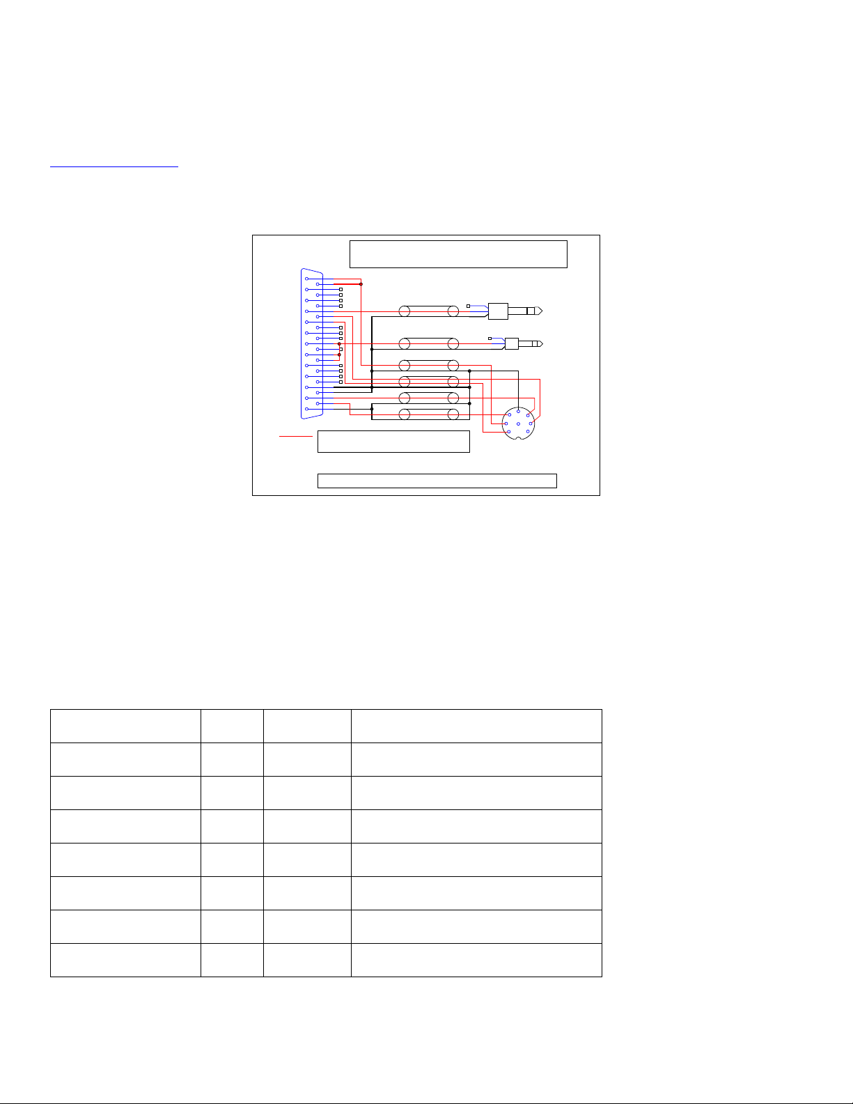
6.5 Rig Hookup
1
2
14
15
3
16
4
17
5
18
6
19
7
20
8
21
9
13
25
12
24
11
23
10
22
FSK ocFSK pu
CWPTTRet
nc
CIV in
CAT In ttl
Rx Aud Ch2
nc
SQUELCH
PTT oc-
CW oc-
PTT ttl
DGND
CAT In ttl-
CAT Out ttl-
CAT In 232-
CAT Out 232-
CIV pu
CIV out
nc
DGND
Rx Aud Ch1
Tx Aud
AGND
Mates with
Navigator J4
DB25P
CWPTT-
S TR
T
R
S
6.3mm (1/4")
KEY
CI-V
S TR
T
R
S
3.5mm (1/8")
DIN8
1
2
4 5
3
6 7
8
ACC(1)
-----------------1 NC/RTTY
2 GND
3 SEND
4 MOD
5 AF
6 SQLS
7 13.8v
8 ALC
ACC1
IC-275, IC-725, IC-726, IC-732, IC-735, IC-736, IC-737, IC-738,
IC-761 IC-765, IC-775, IC-781, IC-756 (ALL), IC-970, IC-7800
Also IC-718 with ACC conversion cable
RTTY function for IC-718, IC-756, IC-761
IC-765, IC-775, IC-781, IC-7800
Note: All Connectors Shown Viewed from Solder Side of Connector
Navigator
Pin
Icom
ACC Pin
FSK & FSKpu
1,14
RTTY 1 DGND
11,24
GND 2 PTToc-
17
SEND 3 TxAud
25
MOD 4 RxAudCH1
12
AF 5 Squelch
5
SQLS 6 AGND
13
GND
2
Connection to your rig involves installing a cable between the Navigator “Transceiver” connector and your rig. See the
www.USInterface.com
website for a full list of cable dr awings for use with the Na vigator. An example belo w shows the connec tion
of the Navigator to an Icom 756 transceiver.
In this example, CAT is done by using CI-V half duplex protocol, so DB25 pins 7, 8, and 21 are tied together. Pin 28 provides pullup
to +5V for the signal line. These connect to a mono or stereo 1/8” plug.
The CWoc- pin 4, is connected to a 6.35 mm 1 / 4” stereo jack to plug into the rig KEY jack. Note: C W output mimics a stra i ght
key in this application.
The ACC jack provides the remaining signals to be controlled. Shielded cables are used for all signals. Overall length is 3 feet.
Navigator to Icom IC756 (and others)
28

Appendix A Navigator I/O Specifications
1
2
14
15
3
16
4
17
5
18
6
19
7
20
8
21
9
13
25
12
24
11
23
10
22
FSK oc-
FSK pu
CWPTTRet
nc
CIV in
CAT In ttl
Rx Aud Ch2
nc
SQUELCH
PTT oc-
CW oc-
PTT ttl
DGND
CAT In ttl-
CAT Out ttl-
CAT In 232-
CAT Out 232-
CIV pu
CIV out
nc
DGND
Rx Aud Ch1
Tx Aud
AGND
Transceiver DB25S
CWPTT-
Navigator Transceiver Connector – DB25S
Pin
Name
I/O
Description
Type
Polarity
1
FSK OC-
Out
FSK Out
Open collector
Low true
2
CWPTT-
Out
CW PTT
Opto Isolated
Low True
3
NC No Connection
4
CW OC-
Out
CW Out
Open collector
Low true
5
SQUELCH
In
SQUELCH, ties to DCD
TTL
6
RXAUD CH2
In
Receive Audio Channel 2
Audio
7
CI-V IN
In
CAT, CI-V In
TTL
8
CI-V OUT
Out
CAT, CI-V Out
Open collector
9
Out
CAT Out RS232
RS232
Low true
10
Out
CAT Out TTL
TTL
Low true
11
DGND
Digital Ground
12
In
Receive Audio Channel 1
Audio
13
AGND
Analog Ground
Audio
The Navigator transceiver interface connector is a DB25S (female). The mating connector for the cable is a DB25P (male).
A layout of the c onnector is shown be low. The pin arrange ment is the same as sho wn in the diagram. T his is the view
looking at the conne ctor on the back panel. The descriptions of these signals i s shown in the table follo wing, “Navigator
Transceiver Connector – DB25S”
29

14
FSK PU
Out
4.7k ohm resistor to +5v
Pull up
15
CWPTTRet
CW PTT Return
Opto Isolated
16
PTT TTL
Out
PTT TTL
TTL
17
PTT OC-
Out
PTT Open Collector
Open collector
Low true
18
NC
No connection
19
CATIN TTL
In
CAT In TTL
TTL
20
NC
No connection
21
CI-V PU
Out
4.7k ohm resistor to +5v
Pull Up
22
CATIN 232-
In
CAT IN RS232
RS232
Low true
23
CATIN TTL-
In
CAT IN TTL
TTL
Low true
24
DGND
Digital ground
Digital Ground
25
TX AUD
Out
TX Audio
Audio
Navigator General Purpose RS232 Connector – DB9P
Navigator RS232 Serial COM Port
Pin
Name
I/O
Description
Type
1
DCD
In
Carrier Detect
RS232
2
RXD
In
Receive Data
RS232
3
TXD
Out
Transmit Data
RS232
4
DTR
Out
Data Terminal Ready
RS232
5
GND Ground
6
DSR
In
Data Set Ready
RS232
7
RTS
Out
Request To Send
RS232
8
CTS
In
Clear To Send
RS232
9 No connection
30

31

I/O Signal Level Specifications
TTL – specs per 74AC series
Input level: Max ± 30V
500 mv rms (20 dB atten)
RS232 – specs per MAX232 device
Outputs
High: 4.5 V min,
source 24 ma.
Low: 0.45 V max,
sink 24 ma.
Inputs
High: 3.15 V Min
Low: 1.35 V Max
Open Collector Drivers MM3904
Outputs
Low: Max 0.3V @ 20
Outputs
High: 5V min, 7 typ
Low: -5V ma x, -7V
typ
Input switc hing point
Pos going: Typ
1.7V, Max 2.4.V
Neg going: Typ. 1.2V,
Min 0.8V
Audio:
Output into 4.7 kOhm load
410 mv rms (Norm atten)
ma.
Sink: 20 ma.
Input: Signal level to produce full level signal into Audio Codec
24 mv rms (20 dB atten)
60 mv rms (Norm atten)
32

Appendix B – Frequently Asked Questions
FAQ about FSK operation with Navigator
Q. I followed the proc edure for setup wi th MixW and FSK w orked fine. Then I sw itched to MMTTY a nd now when I send a
long FSK message, the screen says I am through, but some characters are still being sent at the end. A. The problem is that
the default MMTTY setup puts the stop bits at 1 .5. MixW likes it set to 2. If you did not change the stop bit setting in NavOptions,
then MMTTY sent it’s data faster to Navigator than the output rate. There is a FIFO buffer in the FSK Controller, so that all of the
data was received by Navigator, but it was still sending when MMTTY thought it was through. Fortunately, the FSK controller
provides it’s own PTT, which is synchronized with the output data , so all of the data got sent. Y ou co uld al so have cha nged t he stop
bit rate in MMTTY to 2 bits if you prefer. Also, see NavInst7 MMTTY Setup on you CD-ROM Docs for more information about
setup with MMTTY.
Q. I have a Kenwood transceiver, so I set the FSK polarity in NavOptions to Reverse. I set the invert bit in MixW as well.
The output data seems fine, but reading RTTY signals is ga rbage. A. The polarity of the FSK signal does require reverse with a
Kenwood, but that has nothi ng to do with read ing RTTY signal s. RTTY is usually set to a Lower Side Band mode (LSB) so the
“Normal” settings are set for that. If your transceiver operates in Upper Side Band (USB) then you should use the invert control in
MixW. In your case, uncheck the in vert control in MixW an d you will be fine.
Q. When operating in FSK the RF OUT control on Navigator has no effect on rig output power. A. FSK RTTY is not a sou nd
device mode (unless you are using AFSK). The power level is determined only by the rig RF output power control.
Q. I set my sound device settings to Full Duplex, so I could see wha t the audio input looks li ke while transmitting. In both CW
and RTTY modes, I see very large signals, with appreciable harmonics. Is this going out over the air? A. No, these strong
signals are not go i ng out over the air. Wha t yo u are seei ng i s the squar e wave si de t one s i gnal fr o m the Na vi gato r Mo nit or b eing fe d
back to the a ud io i nput c ha nn e l. In t he c a se of b o th CW a nd RT T Y , o nl y the d i gi ta l co nt r o l si gna ls fo r CW and FS K a r e b e ing se nt to
the rig.
FAQ about WinKeyer operation with Nav i gat or
Q. When I send data from the macros, or when I type on the keyboard, the characters echoed in the Rx window have ##
between the characters, like C##Q### C##Q###. How do I fix this? A. You need to replace the standard WinKeyer co nfi g fi le in
the MixW directory wit h the one on the Navigator Distribution disk. MixW was written to support WinKeyer1, the WinKeyer2
requires that the keyer be closed, then opened again. The new WinKeyer co nfig file fi xes this. See NavInst4 MixW Install on your
CD-ROM for details.
Q. The upper and lower limits of the WinKeyer speed control see m to be fixed at 5 wp m to 35 wpm. How can I chang e this?
A. The lower limit and range are set in the MixW WinKeyer config file. The section is at the end of the file. It looks like this:
[Setup Speed Pot]
33

MINWPM=5
WPMRANGE=30
POTRANGE=255
Change MINWPM and WPMRANGE to meet your needs. Leave POTRANGE at 255. You can use the Windows Notepad editor to
change this. Save the file, quit MixW and restart it again and the new values will take effect.
Q. I want to change some of the weighting parameters for WinKeyer. Is this done in t he WinKeyer config file? A. Y ou c ould
do it in the WinKeyer config file, but the eas iest way is to use the WK2MGR utility progra m supplied on the CD ROM. See section
NavInst6 on t he CD-ROM Do cs for information about this utilit y program.
Q. I need to reverse the paddles on my iambic keyer. Do I need to change my cable to do this? Q. No need to re-wire your
keyer. Check the “Swap” box in WK2MGR and save the settings to reverse paddles.
Q. My WinKeyer was working, and I made so me changes using WK2MGR. Now it doesn’t key the rig, although I do get
sidetone from Navigator. A. Check the WK2MGR setting of Output Config. It should be set to “Port1, ST On”. You probably set
it to Port2. Navigator i s wired to the Por t1 output for CW control. Also check that the WinKeyer config file is loaded into MixW
directory.
Q. My rig has a sidetone of 800 Hz, but MixW shows the offset to be 600 Hz on the waterfall. I set the sidetone in WKMGR to
800, but the water fall doesn’t cha nge. A. In M ixW, t he setti ng for CW offset is in the Confi gure / TRC VR CAT /PTT menu. Se t
CW Pitch to match your rig. The waterfall will no w show an offset matching the sidetone. Also, che ck that the CW is LSB is
checked, if your rig has LSB CW.
FAQ About Power Levels
Q. I had my sy stem al l set up for TX Lev el, the n ran some other progra ms. When I brought t he syste m up aga in, the pow er
levels were way down. What happened? A. Most likely, the PC audio level sliders on the output volume control panel were
changed by another application. Use a free program like QuickMix (http://www.ptpart.co.uk/quickmix/
power levels when you start yo ur a pplication program
Q. I notice that when I move my cursor to 3000 Hz offset, the power level really drops off. A. Your rig is an SSB r ig, wit h an
audio band pass cor ner fre que ncy of ar ound 230 0 Hz. When you mo ve t he cur sor on t he wat erfa ll abo ve t he cor ner fr eque ncy of the
rig output fil ter, mo st of t he aud io dri ve has b een c ut off. Same thing happens on the lower end of the filter. A good rule of thumb is
to keep the cursor from about 500 Hz to 2200 Hz offset. If the signal you want to contact is outside of that, move the base frequency
on your rig.
Q. Even if I stay within the trans mit pass band, I see a difference in output power with different settings. A. The transmit audio
band pass filter on many rigs is any thing but flat topped. Some rigs have a measured variation of 3dB across the pass band. The
advantage o f having a physica l control on the Navigator is that the power level is easily adjusted as opposed to using software level
controls.
Q. When I change bands, the power output changes for the same cursor offset. A. This is typical of SSB transmitters.
Normally, the ALC takes care of these differences, since for voice t he levels are boo sted to attain a full so und anyway. W ith digital
modes, you are operating in the linear range, below the ALC level. Use the RF OUT control on Navigator to bring the level to where
you want it.
Q. What about other modes than PSK? A. Sound device generated modes such as MFSK16, Olivia, MT63 and AFSK are
frequency shifting modes, running at about 100% duty cycle. The settings you use for PSK should be maintained for these modes as
well, mainly to protect your rig from overheating as well as d isto rtion.
) to automatically set your
34

Q. What about FSK RTT Y and CW? How do I adjust the pow er level with those modes? A. These modes do not use the
Audio Codec to generate the signal. The power levels are determined within your rig. Use the rig power level to control output
power.
Q. I want to run my rig at higher than 50% level – how do I ensure that my signal is clean? A. If you do this, you sho uld use an
external monitoring device such as the PSK meter (www.ssiserver.com/info/pskmeter/) or an IMD meter ( www.USInterface.com
Set your rig o utput level to whatever level you want as max, and then monitor your quality using one of these meters. Again, be
careful of the heat level of your r ig if yo u follow this method.
).
35

Appendix C CD-ROM Contents
Note: The Navigator_Install portion of the CD is copied to the Shared Document or Public Documents section of your hard drive. For
XP and Vista:
XP: C:\Documents and Settings\All Users\Documents\Navigator_Install
Vista: C:\Users\Public\Public Documents\Navigator_Install
Nav_Contents\Navigator_Install\Docs
Navigator Manual Users Manual
NavInst 1 Intro Installation Manual Introduction
NavInst 2 Driver Installatio n Manual Driver Install
NavInst 3 NavOpts Installation Manual NavOpts Install
NavInst 4 MixW Install Installation Manual MixW Install
NavInst 5 MixW Setup Installation Manual MixW Se tup
NavInst 6 WinKeyer Test Installation Manual WinKeyer Setup
NavInst 7 MMTTY Setup I nstallation Manual MMTTY Setup
NavInst 8 DM780 Setup Installation Manual HRD / DM780 setup
Nav_Contents\Navigator_Install\Docs\HRD
HRD Ham Radio Deluxe (HRD) and
DM780 Installation
Nav_Contents\Navigator_Install\Docs\WinKeyer Docs
WinKeyer USB Ma nual WinKeyerer2 Manual
WK2_SW_Guide WinKeyerer2 Software Guide
Nav_Contents\Navigator_Install\Olivia\MixW
ModeOlivia.dll Olivia mode .dll
Olivia_readme.txt Olivia mode read me file
Nav_Contents\Navigator_Install\Utilities
FTClean
FTClean FT D I Clea n util ity
36

FTDIUNIN FTDI Uninstaller
USBView
USBView Microsoft USB Viewer
Nav_Contents\Navigator_Install\WinKeyer\MixW\
WinKeyer Correction for WinKeyer V2.1
37

Appendix C: CD ROM Contents, continued
Nav_Contents\Navigator_Install\Docs\HRD
Ham Radio Deluxe (HRD) and
DM780 Installation
NavPrograms\Digipan\ Digipan 20 a pplication
NavPrograms\MixW\ MixW installation programs
NavPrograms\MixW Modes\ Config file for WinKeyer V2.1
NavPrograms\NavDrivers\
WinXP2000\ 32 bit drivers for 2000, XP & Vista
Vista 32 bit drivers for 2000, XP & Vista
Win 7 32 bit drivers for 2000, XP & Vista
Win 8 32 bit drivers for 2000, XP & Vista
NavPrograms\NavOptions\ Installation files for Nav Options SW
NavPrograms\WinKeyer\WinKeyer Apps\
Readme Readme file for apps programs
WinKeyerer2_Setup Setup program for WinKeyerer2 SW
WK2MGR_Setup Setup program for WK2MGR
WKTest_Setup Setup program for WKTest
WinKeyer Apps
WinXP2000 32 bit drivers for 2000, XP & Vista
For manual loading of drivers
Notes
38

39
 Loading...