

Page 1
TT
imewaveimewave
T
imewave
TT
imewaveimewave
NoiseNoise
Noise
NoiseNoise
DSPDSP
DSP
DSPDSP
-599zx-599zx
-599zx
-599zx-599zx
DSP Noise & QRM Filter,
RTTY Modem
Radio/Sound Card Interface
Timewave Digital Signal Processing (DSP) tech-Timewave Digital Signal Processing (DSP) tech-
Timewave Digital Signal Processing (DSP) tech-
Timewave Digital Signal Processing (DSP) tech-Timewave Digital Signal Processing (DSP) technology provides superior pernology provides superior per
nology provides superior per
nology provides superior pernology provides superior per
ing QRM and QRN. No other technology can doing QRM and QRN. No other technology can do
ing QRM and QRN. No other technology can do
ing QRM and QRN. No other technology can doing QRM and QRN. No other technology can do
what DSP can!what DSP can!
what DSP can!
what DSP can!what DSP can!
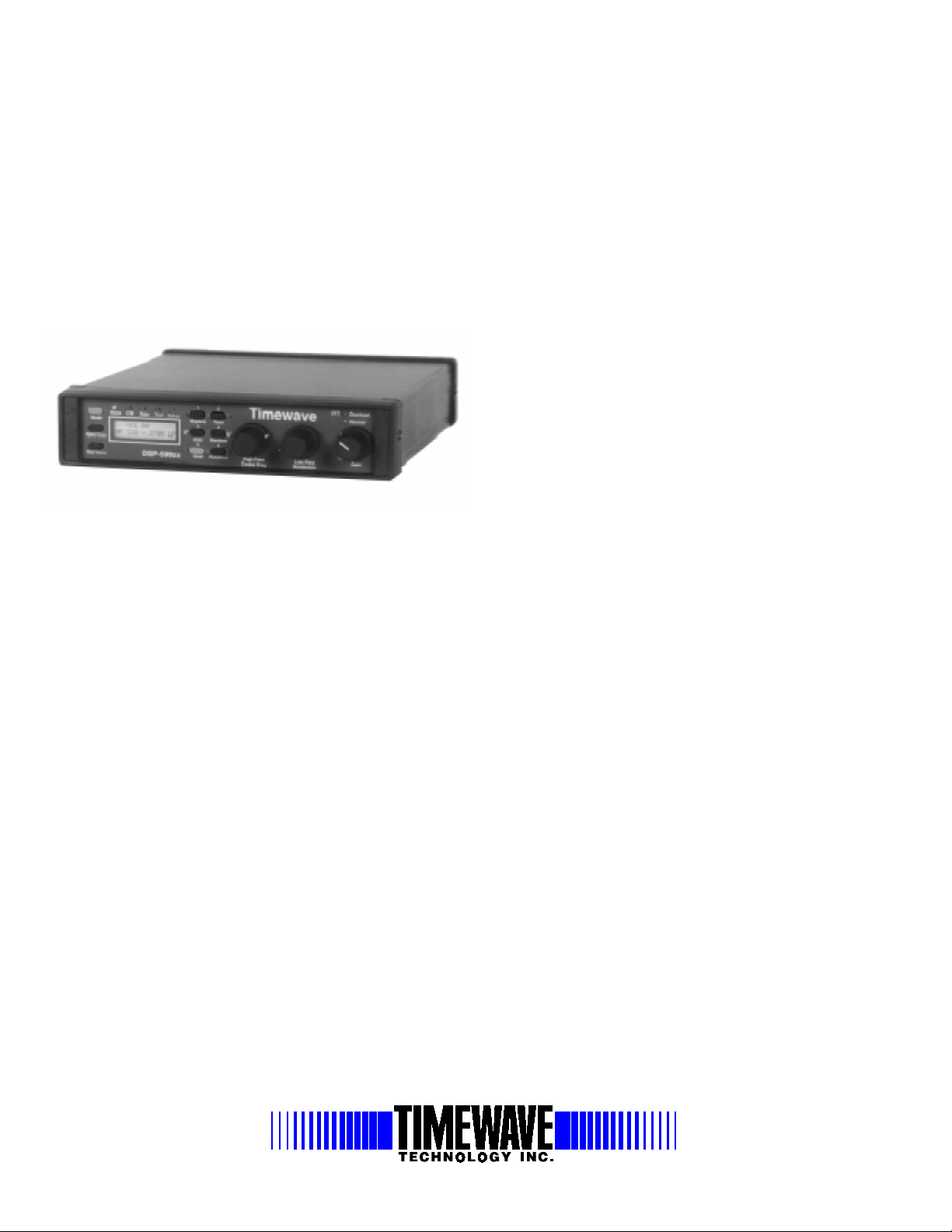
The Timewave DSP-599zx is the latest generation DSP filter incorporating the newest high speed CPU. The extra power gives the user unparalleled features and field upgradeable for the future. The new LCD
display, push buttons, and Visible Memory™ let you see the exact
settings of the filter. The optical encoders give the operator continuous
tuning of filters.
NOISE REDUCTION
The noise reduction functions of the DSP-599zx operate by examining a
characteristic of signals and noise called correlation, and dynamically filtering out the undesired noise. The degree of correlation is relative. Random noise such as white noise or static is uncorrelated. Speech is moderately correlated. Pure tones such as heterodynes are highly correlated. The
DSP-599zx measures correlation and automatically filters out noise that is
outside its correlation threshold-holds.
DATA and BANDPASS FILTERS
Narrow band signals like CW an R TTY require bandpass f ilters with steep
skirts and linear phase response. Linear phase response maximizes the
unusable signaling rate for a given bandwidth and minimizes ringing often
heard on other types of extremely sharp filters. Filter skirts are so steep
that a signal literally falls off the edge of the passband as you tune through
a signal. Bandwidths range from 10 Hz to 600 Hz, and center frequencies
from 200 to 2150 Hz. Narrow filters are useful for trying to dig out ex-
formance in reduc-formance in reduc-
formance in reduc-
formance in reduc-formance in reduc-
Killer!Killer!
Killer!
Killer!Killer!
••
NEW! Binaural CWNEW! Binaural CW
•
NEW! Binaural CW
••
NEW! Binaural CWNEW! Binaural CW
mode for sound card Interfacemode for sound card Interface
mode for sound card Interface
mode for sound card Interfacemode for sound card Interface
••
Hyperspeed DSP Processor 36.8 MIPS with 80 KBHyperspeed DSP Processor 36.8 MIPS with 80 KB
•
Hyperspeed DSP Processor 36.8 MIPS with 80 KB
••
Hyperspeed DSP Processor 36.8 MIPS with 80 KBHyperspeed DSP Processor 36.8 MIPS with 80 KB
RamRam
Ram
RamRam
••
Field upgradeable design keeps you up to dateField upgradeable design keeps you up to date
•
Field upgradeable design keeps you up to date
••
Field upgradeable design keeps you up to dateField upgradeable design keeps you up to date
••
LCD display for Visible Memory™ andLCD display for Visible Memory™ and
•
LCD display for Visible Memory™ and
••
LCD display for Visible Memory™ andLCD display for Visible Memory™ and
Calibrated Filters™Calibrated Filters™
Calibrated Filters™
Calibrated Filters™Calibrated Filters™
••
Wideband filter for AM and FM (VHF & UHF)Wideband filter for AM and FM (VHF & UHF)
•
Wideband filter for AM and FM (VHF & UHF)
••
Wideband filter for AM and FM (VHF & UHF)Wideband filter for AM and FM (VHF & UHF)
••
Continuous filter tuning up to 5 kHz usingContinuous filter tuning up to 5 kHz using
•
Continuous filter tuning up to 5 kHz using
••
Continuous filter tuning up to 5 kHz usingContinuous filter tuning up to 5 kHz using
optical encodersoptical encoders
optical encoders
optical encodersoptical encoders
••
VV
oice Lowpass, Highpass from 100 - 5.0 kHzoice Lowpass, Highpass from 100 - 5.0 kHz
•
V
oice Lowpass, Highpass from 100 - 5.0 kHz
••
VV
oice Lowpass, Highpass from 100 - 5.0 kHzoice Lowpass, Highpass from 100 - 5.0 kHz
••
CW and Data 10 Hz to 600 Hz wideCW and Data 10 Hz to 600 Hz wide
•
CW and Data 10 Hz to 600 Hz wide
••
CW and Data 10 Hz to 600 Hz wideCW and Data 10 Hz to 600 Hz wide
••
NEW! PSK31 and SNEW! PSK31 and S
•
NEW! PSK31 and S
••
NEW! PSK31 and SNEW! PSK31 and S
••
Manual notch Heterodyne Eliminator™Manual notch Heterodyne Eliminator™
•
Manual notch Heterodyne Eliminator™
••
Manual notch Heterodyne Eliminator™Manual notch Heterodyne Eliminator™
tremely weak signals from noise and QRM. The wider filters allow easy
tuning and listening to multiple CW signals simultaneously. Data filters
supported in this filter are RTTY, AMTOR, PacTOR, G-TOR™, HF
Packet, SSTV, WeFAX, SITOR and CLO VER. RTTY has two methods
of being used in addition to regular filtering. You have a complete data
modem designed for RTTY. You can use the remodulator mode that detects and regenerates the mark and space to the modem.
VERSION 5.01 ENHANCEMENTS
Timewa ve’ s DSP-599zx latest enhancements ha ve something for every
operator; CW Spotlight, Binaural CW , new noise processing techniques
for the phone operator and SWL community. T he PC/Radio mode allows
you to explore the new sound card based implementations effortlessly .
TEST INSTRUMENTS
An added benefit of the powerful DSP processor and LCD display in the
DSP-599zx is a Test Instrument mode. This mode is designed to provide
the audio test instruments necessary for normal maintenance and setup of
audio circuits in radio equipment installations. A low distortion audio sine
wave generator and an audio millivoltmeter cover the frequency range
from 20 Hz to 10 kHz. The millivoltmeter measures true rms and peak, as
low as 1 mV, and the sine wave generator output is calibrated in the same
units. The sine wave generator and the milli voltmeter operate simultaneously
for gain and frequency response measurements.
, CW Spotlight and RADIO/PC, CW Spotlight and RADIO/PC
, CW Spotlight and RADIO/PC
, CW Spotlight and RADIO/PC, CW Spotlight and RADIO/PC
STV filtersSTV filters
STV filters
STV filtersSTV filters
FIRST to simultaneously reduce noise, kill heterodynes and QRM!27 Empire Dr
27 Empire Drive, Suite 110 St. Paul, MN 55103 USA
651-489-5080 Voice 651-489-5066 F ax http://www.timewave.com E-mail: [email protected]
Page 2

DSPDSP
DSP
DSPDSP
-599zx Specifications-599zx Specifications
-599zx Specifications
-599zx Specifications-599zx Specifications
AUDIO INPUT
Impedance input 20 K ohms or 22 ohms, jumper selectable
signal range for full output 10 mV to 1.0 volt, front panel programmable
___________________________________________________________________________________________________________________________________________________________________________________________________________________________________________________
AUDIO OUTPUT
Speaker output power 1 watt into 8 ohms at 13.8 VDC, both channels A&B oper ating
Line output 0 dB, referenced to input level, into 10K ohms. Not controlled by gain control
___________________________________________________________________________________________________________________________________________________________________________________________________________________________________________________
Headphone jack 1/4” two circuit jack, use stereo headphones to use all functions, mono headphones for most functions.
3 watts into 4 ohms at 13.8 VDC, output channels A&B bridged
NOISE REDUCTION FILTERS
Random Noise Reduction entire freq. range of selected Up to 20 dB, varies with Adaptive 5 msec max
Heterodyne Reduction entire freq. range of Up to 50 dB, varies with Adaptive 5 msec max
(multiple automatic notch) selected bandpass filter noise characteristics
(manual notch)
Note: The random noise reduction and bandpass filters can operate simultaneously.
___________________________________________________________________________________________________________________________________________________________________________________________________________________________________________________
The random noise reduction, tone notch and highpass/lowpass filters can operate simultaneously.
Frequency range Attenuation Type Delay
bandpass filter noise characteristics.
Noise reduction aggressiveness
front panel adjustable.
BANDPASS FILTERS
CW Filters Bandwidth = 10 Hz to 600 Hz, 10 Hz steps FIR Linear BW less than 20 Hz
CW Marker Tone Sine wave at center freq. of selected CW filter. BW greater 20 Hz
___________________________________________________________________________________________________________________________________________________________________________________________________________________________________________________
Center freq. = 300 to 1600 Hz., 5 Hz steps phase 64 msec max
40 msec max
DATA FILTERS
RTTY, AMTOR, 12 steps. outside the passband phase
PacTOR, G-TOR, Center freq. = 2210 Hz. plus option
HF Packet of 1700(default), 1360, 1300, 1530 or
SSTV 1100-1300 Hz & 1500-2300 Hz 50 dB at 75 Hz outside the Composite 21 msec max
WeFAX 1500-2300 Hz 55 dB at 75 Hz outside FIR Linear 21 msec max
CLOVER 2000-2500 Hz 55 dB at 75 Hz outside FIR Linear21 msec max
___________________________________________________________________________________________________________________________________________________________________________________________________________________________________________________
Bandwidth = 100 Hz to 600 Hz, 40 dB at 60 Hz FIR Linear 38 msec max
2125 Hz.
passband FIR Linear
phase
the passband phase
the passband phase
VOICE FILTERS
Highpass Corner freq. = 20 to 1000 Hz., 60 dB at 180 Hz. FIR Linear 24 msec max
Lowpass Corner Freq. = 1000 to 5000 Hz., 60 dB. at 180 Hz. FIR Linear of highpass &
___________________________________________________________________________________________________________________________________________________________________________________________________________________________________________________
10 Hz. steps. outside the passband phase for any combination
10 Hz. steps outside the passband phase lowpass Filters
SIGNAL PROCESSING
A-D/D-A Converter 16 bit linear, sigma-delta conversion, dual channel
___________________________________________________________________________________________________________________________________________________________________________________________________________________________________________________
Signal Processor 16 bit, 27 ns Analog Devices ADSP-2181 with 80 kb of memory on board
TEST INSTRUMENT
Audio Generator Sine wave tunable from 20 Hz to 15 kHz.
Audio millivoltmeter True RMS from 10 uV. to 2 V., 20-20 kHz calibr ated in volts, dBm @ 600 ohms, relative dB
Sine wave distortion less than 1%
___________________________________________________________________________________________________________________________________________________________________________________________________________________________________________________
MEMORY
Six Memories All configuration setups can be stored and recalled (except volume control setting)
___________________________________________________________________________________________________________________________________________________________________________________________________________________________________________________
DISPLAY 2x16 alphanumeric characters, dot-matrix, yellow-green backlit LCD.
___________________________________________________________________________________________________________________________________________________________________________________________________________________________________________________
DIMENSIONS
Size 7.6 in. wide x 8.5 in. deep x 1.9 in. high (193 mm wide x 216 mm deep x 48 mm high)
___________________________________________________________________________________________________________________________________________________________________________________________________________________________________________________
Weight 2.0 lb. (0.9 Kg.)
POWER 12-16 VDC @ 1A, Fuse 1.5 A 5 mm x 20 mm
___________________________________________________________________________________________________________________________________________________________________________________________________________________________________________________
Note: RTTY, AMTOR, PacTOR, G-TOR and HF Packet data filter bandwidths are specified at -3 dB points to comply with traditional data filter specification
methods. All other filter bandwidths are specified to comply with conventional DSP FIR filter parametric descriptions.
 Loading...