

Page 1

DSP-599zx
Audio Noise
Reduction Filter
Features
Revision 1.1
TECHNOLOGY INC.
Page 2

Congratulations
Copyright
You are reading about the most advanced digital signal processor
available. Timewave Technology Inc. occasionally offers performance
enhancing up dat es to its pr oduct s. Upda tes a nd cor r ections to infor mat ion
and s pecifications will b e ma de t o this F eatu res M anual when needed.
1994, 1995, 1996 by Timewave Technology Inc. All rights reserved.
Printed in USA
Under the copyright laws, this manual can’t be reproduced in any form
withou t prior writ ten per mis sion from Timewave Technology Inc.
Timewave Technology Inc. strives to deliver the best product to our
cus tomers. As par t of this goal, we a re cons tantly trying t o improve ou r
pr oduc t s. Timewave Technology Inc., t her efor e, r es erves t he r ight to ma ke
changes to produc t sp ecif ic at ions or doc umentation withou t prior notice.
This Features manual may contain errors, omissions or “typos.” Please
send your comments, suggestions a nd c orr ec tions:
Timewave Technology Inc.
2401 Pilot Knob Road
St. Paul, MN 55120 USA
[email protected] E-mail
http://www.timewave.com FAQ and Informa tion
(612)452-5939 Voice
(612)452-4571 Fax
Page 3
Controls
Spkr/Chan
Rcl/Store
Mode
CW
Data
Voice
DSP-599zx
Front Panel
Test
Setup
Timewave DSP-599zx Audio Noise Reduction Fi lter
PTT
1
Bypass
3
AGC
5
Shift
2
Tone
4
Random
6
Function
Timewave
High Pass
Center Freq
Low Pass
Bandwidth
Overload
Normal
Off
Gain
599-002
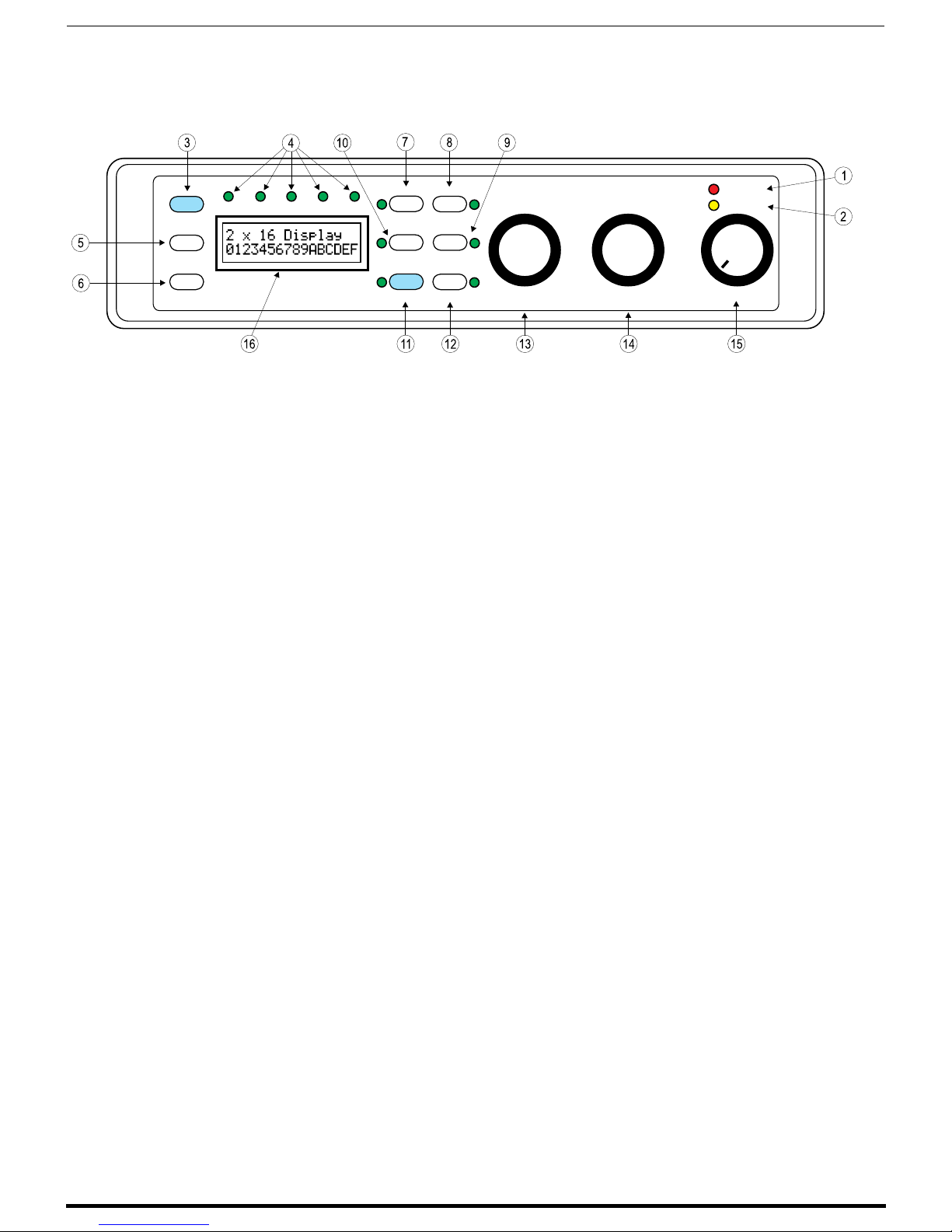
1. PTT/Overload LED
Red LED indicates a too high signal level into
DSP-599zx from receiver. When PTT line from
transceiver is connected, red LED on indicates
PTT is activated.
2. Normal
Yellow LED indicates normal signal level into
DSP-599zx.
3. Mode sw itch
Press to change mode (Voice, CW, Data). Press
[Shift+Mode]
to switch to Setup and Test modes.
4. Voice, CW, Data, Test, and Setup LEDs.
Indicate the selected mode of the DSP-599zx.
5. S pkr/Chan swi tch
Press to toggle speaker on and off. Press
Mode]
to switch from Channel A input to
Channel B input.
[Shift+
6. Rcl/Store switch
To recall memory, press this key and then one of
the switches labeled 1 to 6. To store current
settings in a memory, press
[Shift+Rcl/Store]
then one of the switches labeled 1 to 6.
7. Bypass Switch
Press to Bypass DSP filtering.
8. Tone Switch
Heterodyne elimination for Voice.
Marker Tone for CW and Data. Press
Tone]
to activate manually tuned notch filter.
[Shift+
9. Random switch
Used to turn on random noise reduction. Press
[Shift+Random]
to activate variable noise
reduction.
10. AGC switch
AGC on.
11. Shift switch
This blue switch shifts the function of the next
switch pressed to its function labeled in blue.
12. Function switch
This switch is used to enter into menus and other
specialized functions.
13. High Pass/Center Freq Control
Tunes the high pass filter in the Voice mode.
Tunes the bandpass filter center frequency in CW
and Data mode. In most menu modes, this knob is
rotated to see menu choices. Pressing the knob to
selects the choice.
14. Low Pass/Bandwidth Control
Tunes the low pass filter in the Voice mode.
,
Tunes the bandpass filter bandwidth for CW and
Data mode. Pressing knob will turn off temporary
settings.
15. Gain/Power On/Off
Turns power on and off, and volume control for
speaker output.
16. LCD Display
Backlit 2x16 alphanumeric display of mode,
control, and test settings and data.
Features Version 1.1 3
Page 4
Connectors
Timewave Technology Inc.
St. Paul, Minnesota USA.
Timewave DSP-599zx Audio Noise Reduction Fi lter
A
B
Power
12-16 Vdc
RS-232
Radio A
Back Panel
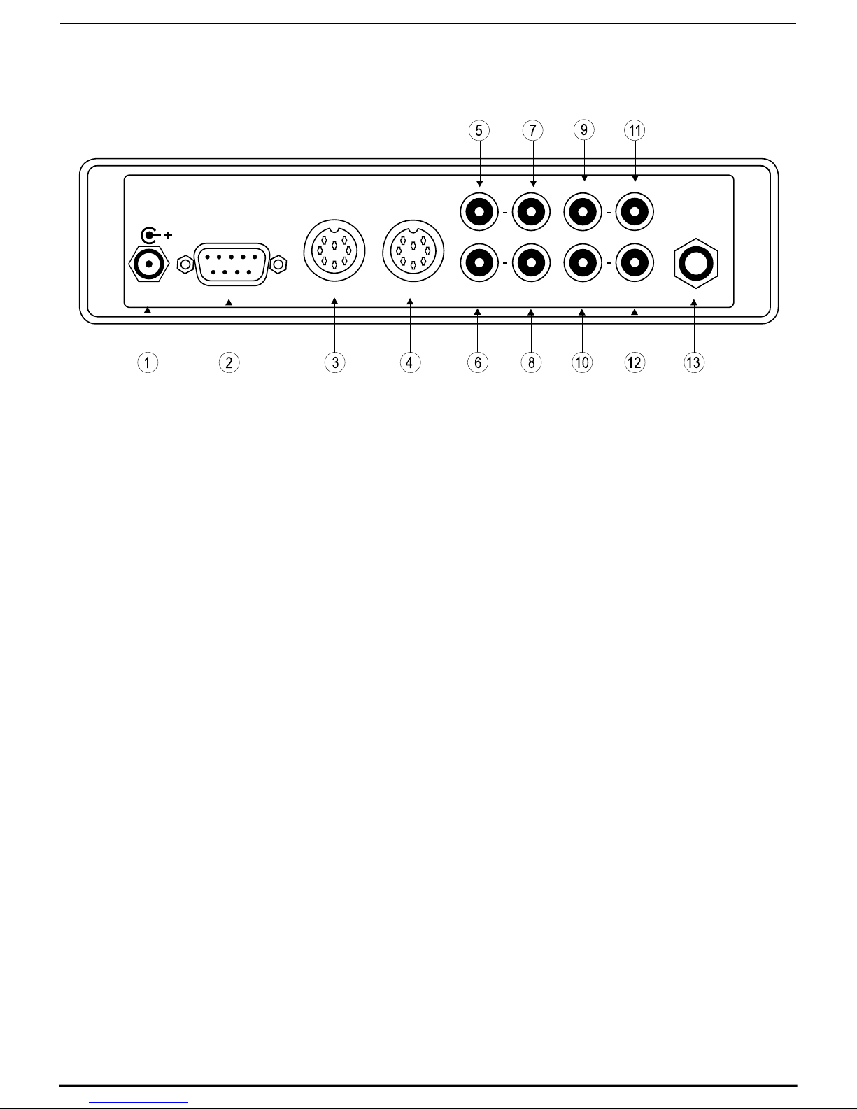
1. Power In
12-16 Volts DC Use 5.5 mm/2.1 mm matching
plug, center positive.
2. RS-232
RS-232 compatible RTTY modem serial output
for computer interface. DB-9F connector. Refer to
chapter 2 for pin configuration.
3. Radio A
Alternative single 8 pin DIN connection for line
out, audio in, PTT out, PTT in, aux. digital in.
Also contains connections reserved for future
options.
4. Radio B
Alternative single 8 pin DIN connection for line
out, audio in, PTT out, PTT in, aux. digital in.
Also contains connections reserved for future
options.
5. PTT Input A
PTT line from transceiver A PTT output. RCA
Phono connector.
6. PTT Input B
PTT line from transceiver B PTT output. RCA
Phono connector.
Radio B
PTT
Input
Audio
Input
Line
Ouput
Speaker
Ouput
Headphones
7. Audio Input A
Audio input from radio speaker output - channel
A. RCA Phono connector.
8. Audio Input B
Audio input from radio speaker output - channel
B. RCA Phono connector.
9. L i ne Output A
Line level output to multimode data controller channel A. Gain control doesn’t vary this output.
RCA Phono connector.
10. Line Output B
Line level output to multimode data controller channel B. Gain control doesn’t vary this output.
RCA Phono connector.
11. S peaker Output A
4-8 ohm speaker output - channel A. RCA Phono
connector.
12. S peaker Output B
4-8 ohm speaker output - channel B. RCA Phono
connector.
13. Headphone Jack
Stereo headphone jack for 1/4” stereo plug.
599-005
Features Version 1.1 4
Page 5
Timewave DSP-599zx Audio Noise Reduction Fi lter
Typical
Transceiver
ANT
See your Operator Manual
for specific information
about PTT output connections
PTT Out
Ext Sp
Timewave Technology Inc.
St. Paul, Minnesota USA.
Power
12-16 Vdc
Center Cond +12Vdc
RS-232
12-16 Vdc 1A
Power
Supply
DSP-599zx
Radio A
Multimode Controller
Radio B
(PK232, KAM +, or other)
connector information
A
B
PTT
Audio
Input
Input
See your Operator
Manual for specific
Line
Ouput
Speaker
Headphones
Ouput
Rx Audio Input
To Stereo/Mono
Headphones
Speaker
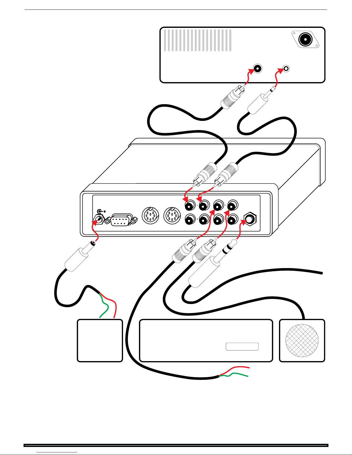
Consult the installation section of this manual for more information on
cables a nd c onnec tions.
Features Version 1.1 5
599-010
Page 6
Voice Mode
CW Mode
Timewave DSP-599zx Audio Noise Reduction Fi lter
1
Mode
Spkr/Chan
Rcl/Store
Voice
CW
DSP-599zx
TestData
Setup
Bypass
AGC
Shift
2
Tone
3
4
Random
5
6
Function
Time
High Pass
Center Freq
599-006
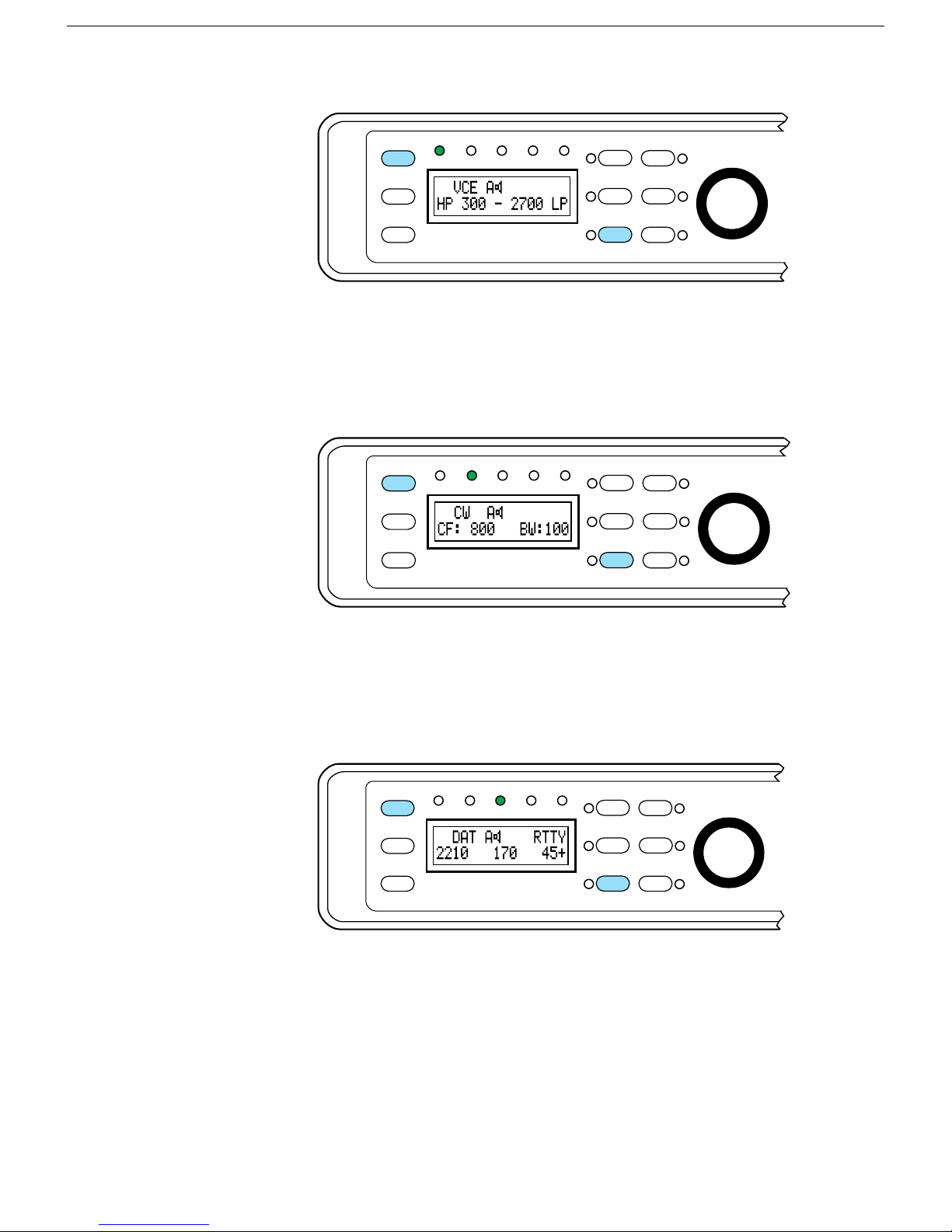
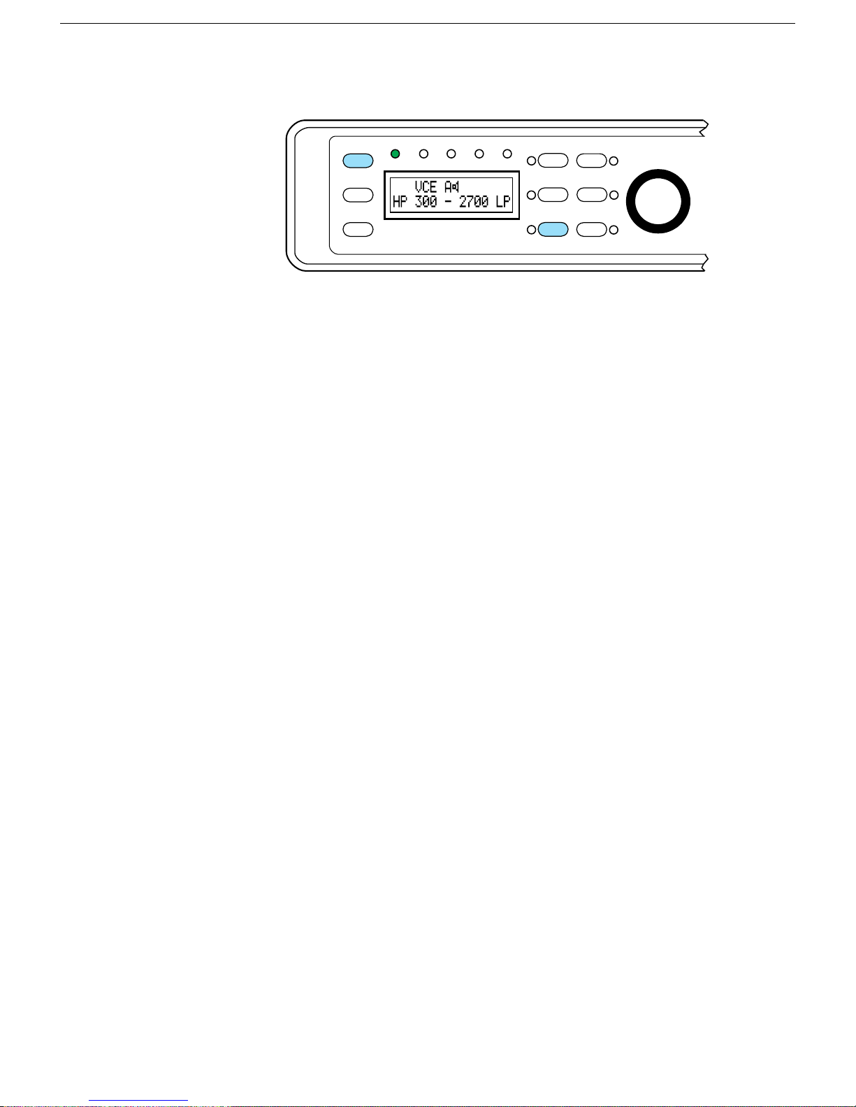
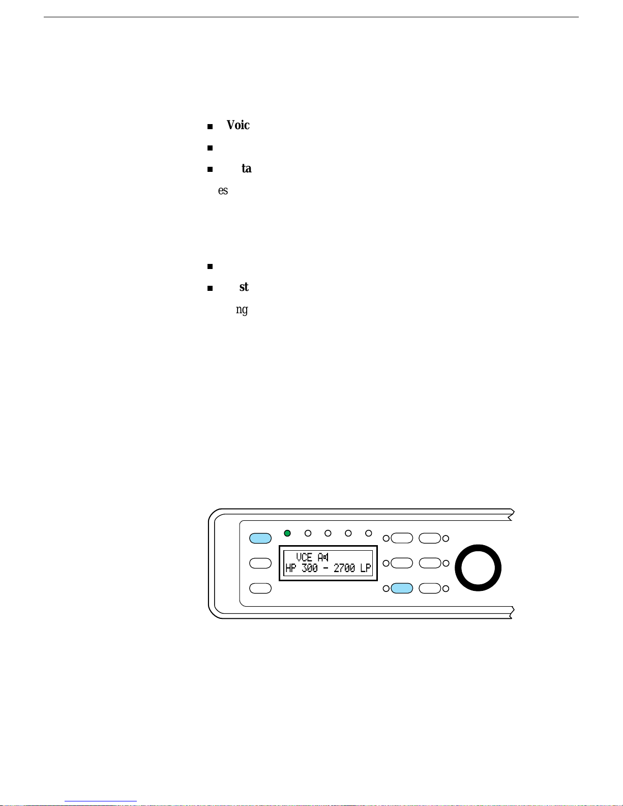
Typical display for Voice mode, 300 Hz to 2700 Hz filter, A channel active
and s peaker on.
Data Mode
1
Mode
Spkr/Chan
Rcl/Store
Voice
Data
CW
DSP-599zx
Test
Setup
Bypass
3
AGC
5
Shift
2
Tone
4
Random
6
Function
Time
High Pass
Center Freq
599-007
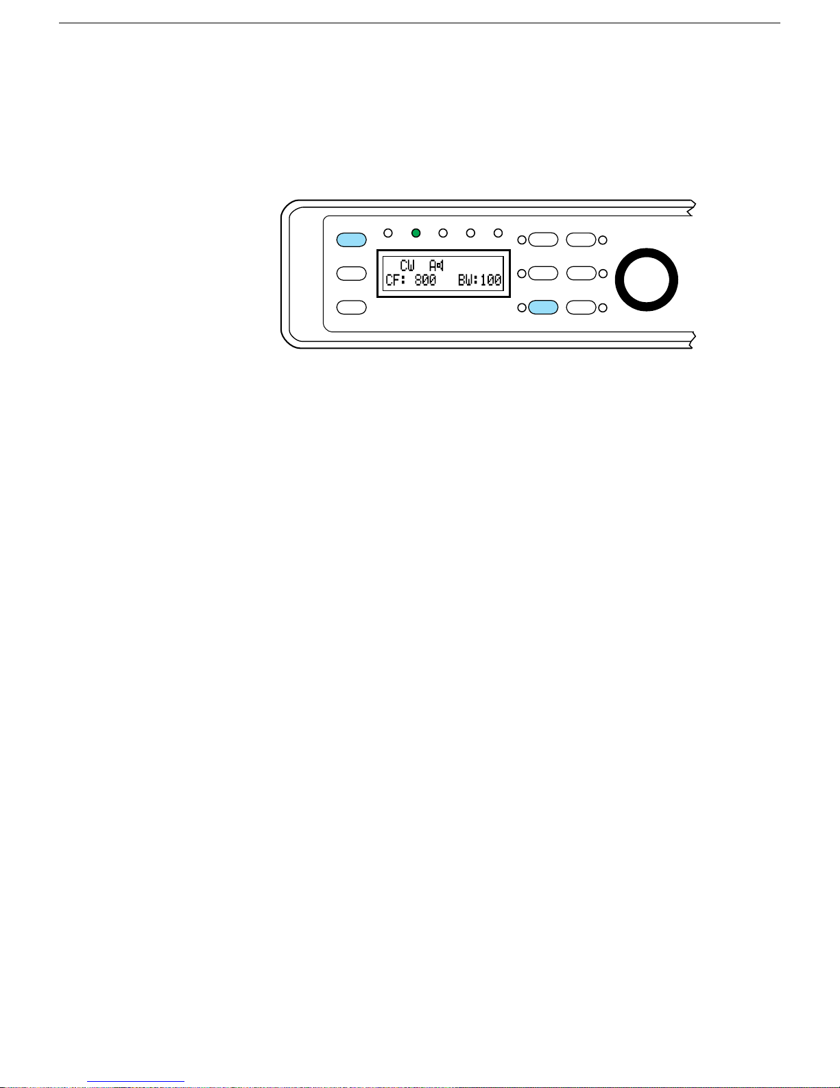
Typical display for CW mode, Center Frequency at 800 Hz and Bandwidth
set to 100 Hz filter, A channel active and speaker on.
1
Mode
Spkr/Chan
Rcl/Store
Voice
Data
CW
DSP-599zx
Test
Setup
Bypass
3
AGC
5
Shift
2
Tone
4
Random
6
Function
Time
High Pass
Center Freq
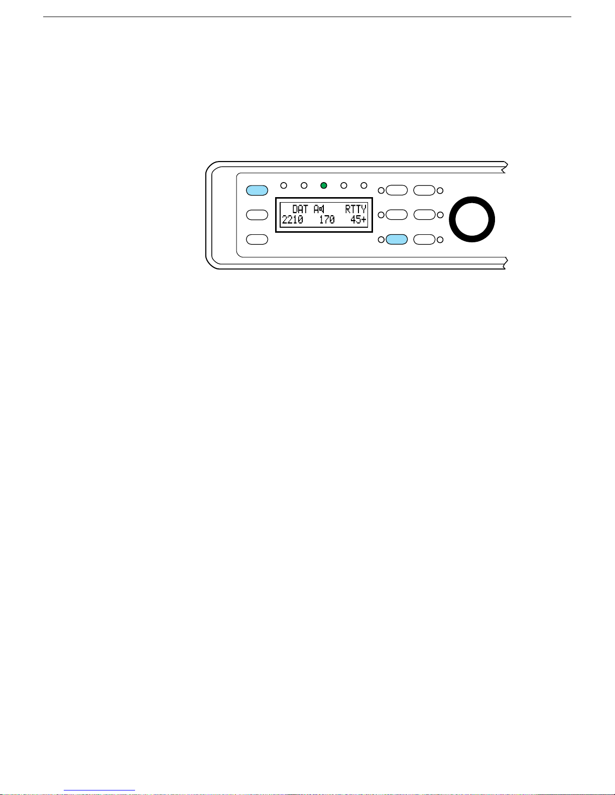
Typical display for RT TY Data mode. Center frequency at 2210 Hz, offset
at 170 Hz and baud rate of 45. A channel active and speaker on.
Features Version 1.1 6
599-029
Page 7

Timewave DSP-599zx Audio Noise Reduction Fi lter
DSP-599zx Introduction
The previous section includes a short summary of both the front panel
controls and the rear panel connectors. Please see
Specifications
cap abilities of the DSP - 599zx.
Digital Signal Processing
D
igital Signal Processing (DSP) is a powerful and complex method of
ana lyzing and modifying ana log signals . Audio s ignals like speech or r adio
data are analog signals. The speech and data signals have fairly well
known and predictable characteristics; however, these characteristics are
quite complex. By converting the analog signal to a digital signal, a
powerful digital signal processor with a special program can analyze the
characteristics of the analog signal. T he digital signal processor can then
modify the digital signal to enhance desired characteristics and to remove
undesir ab le char a cter ist ics s uch a s nois e. T he pr ocessed s ignal is convert ed
back to an analog signal and sent on to a speaker, headphone, or data
contr oller. The resu lt is a signa l with less noise a nd/or fewer da ta err or s. I n
amateur radio terms, DSP is capable of reducing or eliminating QRN
(noise) and QR M (int erferenc e).
at the rear of this document for detailed informat ion on the
DSP-599zx
For a more deta iled dis cu ss ion of digit a l s igna l process ing, cons u lt t he most
recent
ARRL Handbook
.
Features Version 1.1 7
Page 8
DSP-599zx Overview
The DSP-559zx is an extraordinarily versatile digital signal processor
designed for amateur a nd shortwave radio voice, data and CW operation.
The DSP-599zx uses advanced digital signal processing technology to
implement algorithms t hat p erform five basic a u dio funct i ons:
The DSP-599zx combines these five basic functions to reduce noise and
interference and improve radio communication. The DSP-599zx hardware
and softwar e architecture allow easy field upgrade with new features and
algorithms. The same hardware and software architecture also allow
ergonomic mode oriented operation of the DSP-599zx. The LCD alphanumeric dis pla y pr ovides a clear view of op era ting set tings when s witching
between operating modes. The quick-select push buttons and optical
encoders for filter tuning allow ins ta nt mode change wit h tota l r ecall of las t
setting and memories. Front-panel selectable and adjustable inputs allow
you to quickly setup and adjust your DSP-599zx to wipe out noise and
QRM like never before!
Timewave DSP-599zx Audio Noise Reduction Fi lter
Ra ndom nois e reduct ion
Adap tive multi-tone and manu al notch filtering (Tone noise reduction)
Bandpass/Highpass/Lowpass filtering
Signal generation inclu ding FSK RTTY modula tion
Signal detection and measurement inclu ding RTTY demodulation
Here ar e a few more highlight s a mong the many ot her oper a ting fea tu r es of
the DSP-599zx:
Selectable Automa tic Ga in Control
Configurable bypass control
Two selectable inp u t channels
Two configurable output channels
Six memories f or instant recall of user - defined conf igurations
Test inst rument mode for ana lyz ing signals and ot her equipment
Features Version 1.1 8
Page 9
Signal Flow
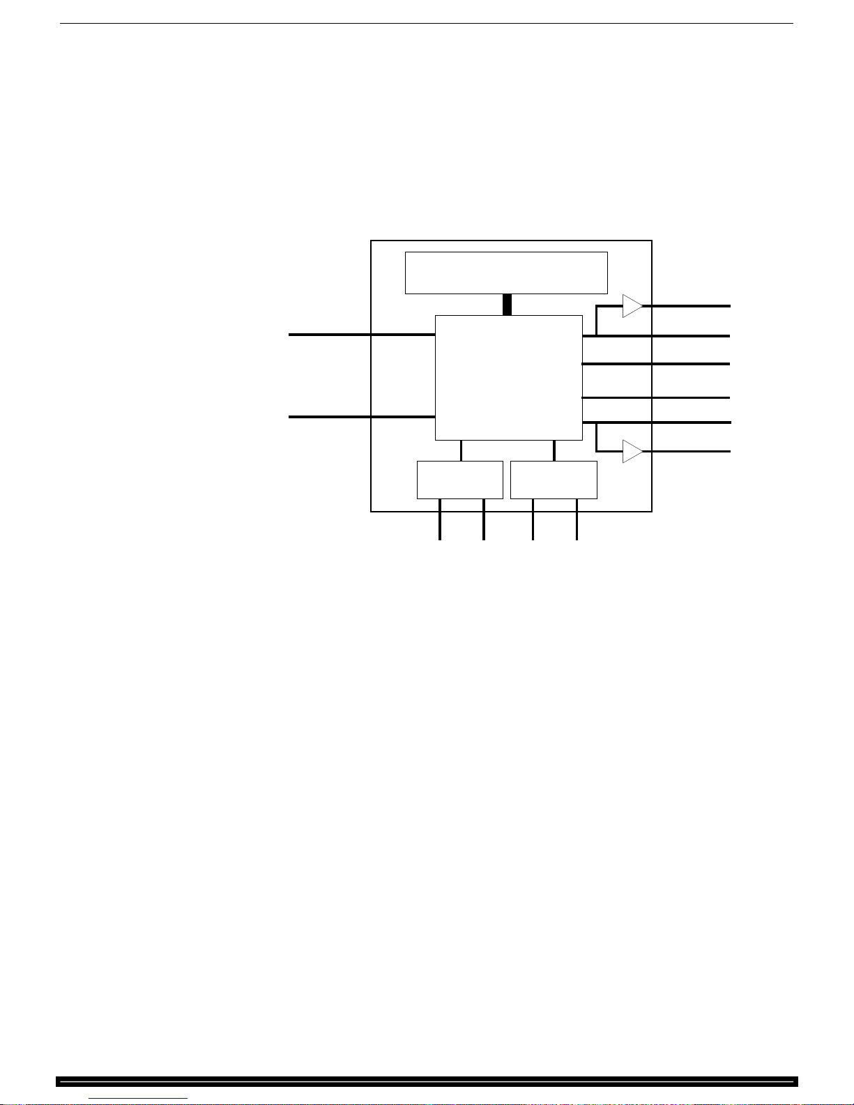
The DSP-599zx converts a nalog s igna ls into digit al s igna ls b efore it r out es
and processes them. The digital signal processor also controls the front
panel switches, encoders , LEDs, LCD display, and ba ck panel inp uts a nd
outputs. This figure is a greatly simplified block diagram of the DSP599zx.
Channel A
Input
Channel B
Input
Timewave DSP-599zx Audio Noise Reduction Fi lter
Timewave DSP 599zx
Front Panel Controls
and Display
Speaker
Chan
}
Chan
}
DSP
Circut
Headphones
Line Out
Line Out
Headphones
Speaker
A
B
PTT
I/O
Data
I/O
DB-9
Connector
599-013
Features Version 1.1 9
Page 10
Timewave DSP-599zx Audio Noise Reduction Fi lter
Features Common to All Modes
Voice
Mode
Spkr/Chan
Rcl/Store
Random/Tone Noise Reduction
The noise reduction functions of the DSP-599zx operate by examining a
characteristic of signals and noise called
filtering out the undesired signals and noise. The degree of correlation is
rela tive. R a ndom noise su ch a s whit e noise or st a t ic is u ncor r ela t ed. S p eech
is moderately correlated. Repetitive or continuous noise such as a
heterodyne is highly corr elat ed. The DS P-599zx measures correlation and
filter s out si gnals and nois e that a re outs ide its corr elation t hresholds. The
amount of noise r educ tion var ies a c cor ding t o the c or r elat ion c ha r a ct er is tic s
of the noise. Typica l nois e r educ tion ra nges fr om 5 dB t o 20 dB for r a ndom
noise and up t o 50 dB for heterodynes.
CW
TestData
Setup
DSP-599zx
1
Bypass
3
AGC
5
Shift
2
Tone
4
Random
6
Function
High Pass
Center Freq
correlation,
Time
599-006
and dynamically
Adaptive Multi-tone and Manual Notch Filtering
(Tone noise reduction)
The DSP-599zx has both an automatic notch filter and a manually tuned
filter. The automatic notch filter is an adaptive multi-tone filter that can
remove multiple tones simultaneously. The automatic multi-tone filter
removes multiple heterodynes almost completely. The
encoder on the front panel t unes the ma nual not ch filter. T he manua l notch
filter is selectable and has a wide bandwidth filter for data signals and a
narrow b andwidth f ilter for CW signals and het erodynes.
Dual Channel Operation
The DSP-599zx is a dual channel device with two sets of inputs and
outputs. The DSP circuit completely processes the selected channel, while
signals on the other channel pass through the DSP circuit without
pr ocessing. Set tings for each channel a re ret ained when switching bet ween
channels.
The two input cha nnels a llow you to c onnect eit her t wo sep a r a te r a dios or a
dual channel radio with two outputs to the DSP-599zx. You may configure
each channel to completely differ ent opera ting modes. Selecting the opposite
channel returns the DSP-599zx to the previous settings on that channel.
[Center Freq]
Features Version 1.1 10
Page 11
Timewave DSP-599zx Audio Noise Reduction Fi lter
This is very handy for t wo rig opera tions when setting one rig to monitor
CW and the other to monitor voice.
1
Mode
Spkr/Chan
Rcl/Store
Voice
CW
DSP-599zx
TestData
Setup
Bypass
AGC
Shift
2
Tone
3
4
Random
5
6
Function
Time
High Pass
Center Freq
599-032
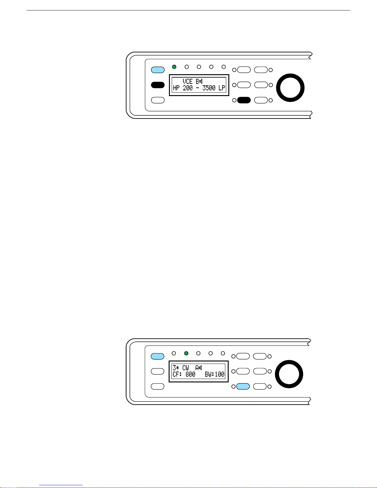
Pressing
[Shift+Chan]
599zx audio gain control simultaneously controls volume level of both
channels.
Setup
channel with respect to the B channel.
Setup
mode also allows you to configure the two output channels
independently. It is possible to configure the Line Out for each channel
differently from the external speaker and headphone outputs. This can be
very convenient when working in one of the D at a modes. T he Line Ou t ca n
then be connect ed t o a multi-mode cont roller.
The DSP-599zx requires external speakers and/or headphones to hear the
audio signal. The DSP-599zx will accept either s t ereo or mono head- phones
with a 1/ 4” plug. Ster eo headphones a re the p referr ed over monau ra l headphones so that you monitor both output channels simultaneously.
Visible Memories
The DSP-599zx has six memories to store complete settings and
configur at ions. P ress ing
and setup configuration except the audio gain control position. Pressing
[Rcl+{#}]
stored in a memory a nd displays them on the L CD.
instantly recalls the complete settings and setup configuration
toggles between channels A and B. The DSP-
mode allows adjustment of the relative volume of the
[Shift+Store+{# }]
(# = 1-6 ) st ores every s ettin g
A
Features Version 1.1 11
Mode
Spkr/Chan
Rcl/Store
Voice
Data
CW
DSP-599zx
Test
Setup
1
Bypass
3
AGC
5
Shift
2
Tone
4
Random
6
Function
Time
High Pass
Center Freq
599-016
Page 12
Timewave DSP-599zx Audio Noise Reduction Fi lter
Automatic Gain Control
The DSP-599zx has switch-selectable automatic gain control to optimize
the signal levels for best filter performance and to enhance listening by
minimizing audib le s ignal level var i ation.
Bypass Control
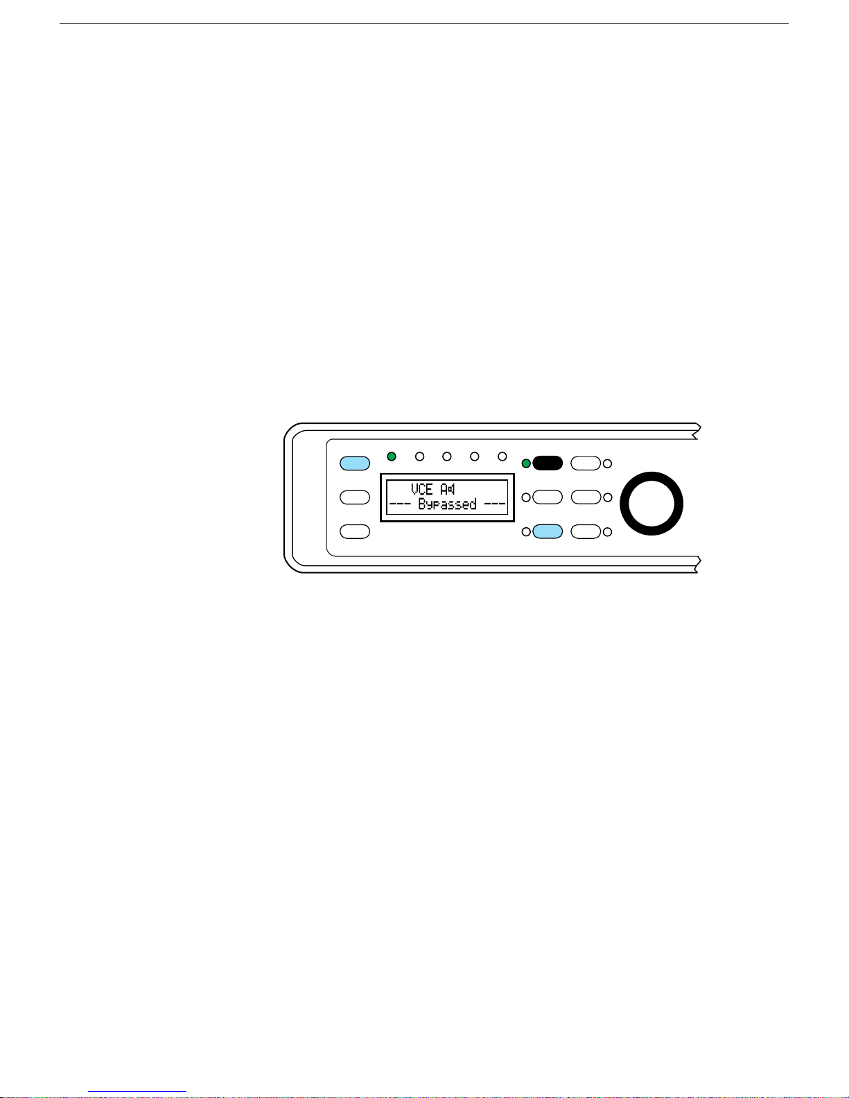
The DSP-599zx has bypass features that vary with the mode of operation.
In voice and C W modes, t he bypas s set ting rou tes t he signal throu gh rela y
contacts to completely bypass the electronic circuitry of the DSP-599zx.
Turning the power off to DSP-599zx uses the same relay bypass method. In
dat a mode, the bypass route is t hrough the D SP pr ocessor. T he amount of
signal delay through the bypass route is equal to the delay through the
processed signal route. The purpose of this delay equalization is to allow
switching between signal processing and bypass without breaking the
hands haking link of modes like PacTO R and G -TOR.
1
Mode
Spkr/Chan
Rcl/Store
Voice
Data
CW
DSP-599zx
Test
Setup
Bypass
3
AGC
5
Shift
2
Tone
4
Random
6
Function
Time
High Pass
Center Freq
599-061
Bypas s resp ects the sta tus of t he spea ker swit ch. I f the sp eaker is t urned
off, b ypass leaves it off . The s peaker will a lways, however, come on when
power is turned off on the DSP-599zx.
Features Version 1.1 12
Page 13
Operating Modes
Timewave DSP-599zx Audio Noise Reduction Fi lter
The DSP-599zx has three normal operating modes that operators will most
often u se:
Voice
CW
Data
Pressing
Voice mod e i n a ci rc ular q ueue.
There are two more modes that operators will normally use during initial
configuration, insta llation, a nd trou bleshooting,
Set-up
Test
Pressing
[Shift+Mode]
pla ces t he unit b a ck in one of t he nor mal op er a t ing modes a ga in. When in a
menu or t est inst ru ment mode, pres sing the
one level. Think of the
button.
Voice Mode
The Voice Mode digita lly processes all a nalog voice signals for all modes
including SSB, AM, FM, and PM. Independently selectable processing
techniques include noise reduction, heterodyne elimination, tunable highpa ss/lowpas s filtering and aut omatic gain cont rol.
[Mode]
[Shift+Mode]
step s fr om Voice mode to CW mode to D ata mode bac k to
once places the DSP-599zx in Test mode. Pressing
again steps to Setup mode. Pressing
middle button
[Mode]
middle knob
at any time
will back you u p
in most cases as a cancel/clear
Features Version 1.1 13
Mode
Spkr/Chan
Rcl/Store
Voice
CW
DSP-599zx
1
TestData
Setup
Bypass
AGC
Shift
2
Tone
3
4
Random
5
6
Function
Time
High Pass
Center Freq
599-006
Page 14
Timewave DSP-599zx Audio Noise Reduction Fi lter
Highpass/Lowpass Filters
The DSP-599zx has highpass and lowpass filters that are independently
tunable with front panel controls. The LCD display shows the corner
frequencies of the filters as they are tuned. There are many uses for the
variable combinations of highpass and lowpass filters that the DSP-599zx
offers. In a typical example of a voice mode application, highpass and
lowpa ss filter s can impr ove a signa l with a poor signal- to-noise ra tio. T he
independent highpass and lowpass filters remove the low and high audio
frequency components that do not contribute significantly to the speech
intelligibility, thus improving signal quality. Another common voice mode
example is the improvement of a S SB s ignal cor r upt ed by a djacent cha nnel
interference (QRM). The steep skirts of the highpass and lowpass filters
allow the operator to eliminate high side and low side interference
independently with minimal impact on the desir ed s ignal.
The DSP-599zx highpass filter adjustment range is from 100 to 1000 Hz
and the lowpass range is from 1000 to 5000 Hz. Although the DSP-599zx
has bandpass filters for CW and the most common data modes, the
selectable highpass and lowpass filter combinations also allow precise
filter ing f or modes su c h as wideshif t RTTY.
Random Noise Reduction
The DSP-599zx random noise reduction has pr oven t o be u sefu l in r edu cing
a wide variety of noise types, including white noise, line noise and static
crashes. The amount of noise reduction varies according to the
char a cter ist ics of the noise. Typical nois e reduct ion r anges f rom 5 dB to 20
dB. It is possible to change the level of aggressiveness within a regular
operating mode withou t going into s et up mode.
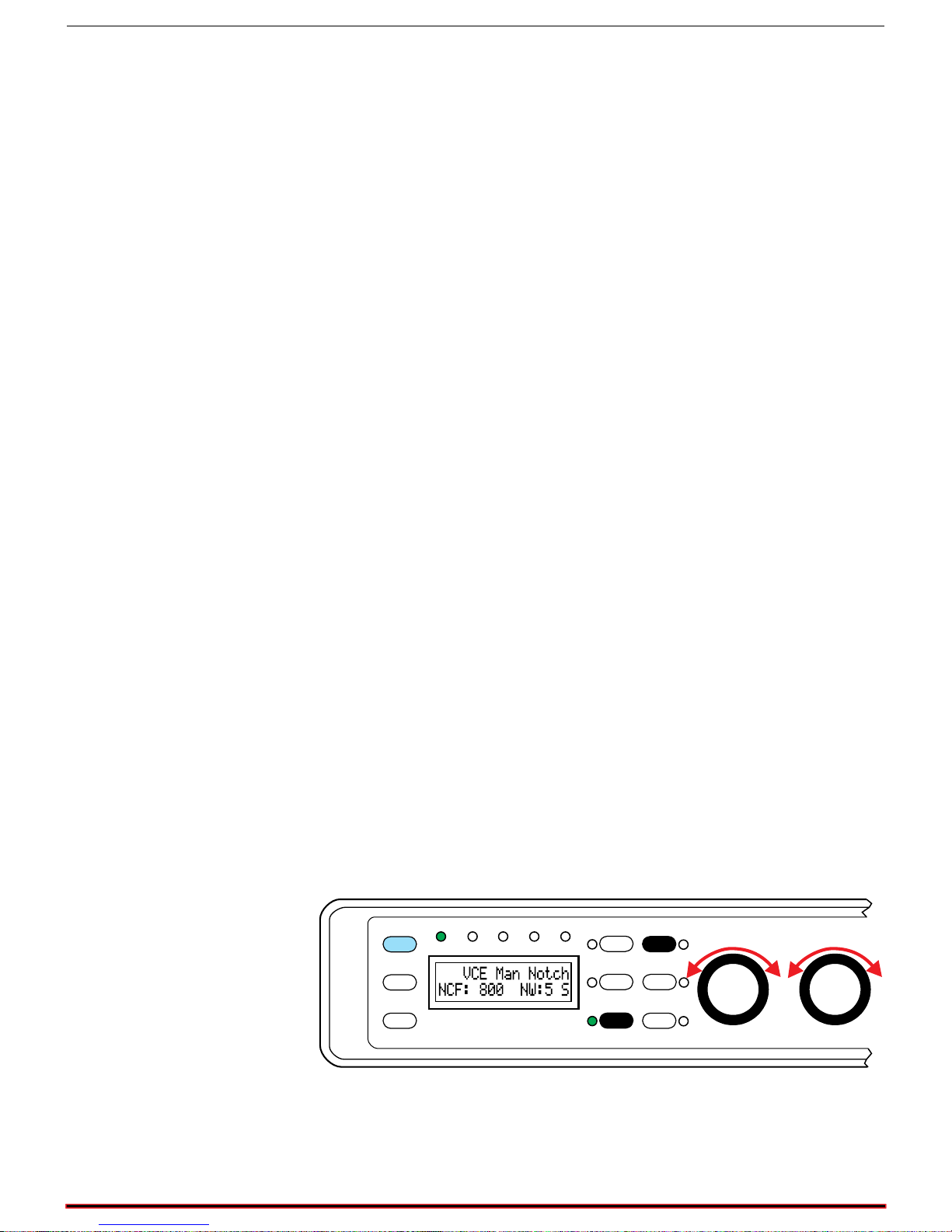
Adaptive Multi-tone and Manual Notch Filtering
(Tone noise reduction)
The DSP-599zx has both an automatic notch filter and a manually tuned
filter. T he automat ic multi-tone filter removes multiple heterodynes a lmost
completely.
1
Mode
Spkr/Chan
Rcl/Store
Voice
Data
CW
DSP-599zx
Test
Setup
Bypass
3
AGC
5
Shift
2
Tone
4
Random
6
Function
Timewave
High Pass
Center Freq
Bandwidth
Low Pass
The manual notch filter is selectable for either a wide ba ndwidth for data
signals and a narrow bandwidth for CW signals and heterodynes. The
center freq uency o f the filter i s ea sily set.
Features Version 1.1 14
599-027
Page 15
CW Mode
The CW Mode digita lly processes ana log CW (Cont inuous Wave) s ignals
for Morse code reception. Independently selectable processing techniques
include noise reduction, tunable bandpass filtering and automatic gain
control.
Bandpass Filters
Mode
Spkr/Chan
Rcl/Store
Timewave DSP-599zx Audio Noise Reduction Fi lter
1
Voice
Data
CW
DSP-599zx
Test
Setup
Bypass
3
AGC
5
Shift
2
Tone
4
Random
6
Function
Time
High Pass
Center Freq
599-007
The DSP-599zx has a fully tunable bandpass filter for use in the CW mode.
The LC D displa y shows the cent er fr equency a nd ba ndwidth of the filt er a s
the oper ator tunes with fr ont pa nel contr ols. Na rr ow ba nd signals like CW
and RTTY require a bandpass filter with steep skirts and linear phase
resp onse. Linea r pha se respons e max imizes the usa ble signa ling ra te for a
given bandwidth and minimizes ringing often heard on other extremely
sharp crystal and au dio f ilters .
The DSP-599zx CW filter has skirts so steep that a signal literally falls off
the edge of the pa ss ba nd as you t une thr ou gh a C W si gnal. Ba ndwidths f or
the bandpass filter range from 10 Hz to 600 Hz, and center frequencies
range from 200 to 1000 Hz. The narrow filter bandwidths are useful for
trying to dig out extremely weak signals from the noise and QRM. The
wider filter bandwidth allows easy tuning and listening to multiple CW
signa ls simultaneously.
Random Noise Reduction
The DSP-599zx random noise reduction has pr oven t o be u sefu l in r edu cing
a wide variety of noise types, including white noise, line noise and static
crashes. The amount of noise reduction varies according to the
char a cter ist ics of the noise. Typical nois e reduct ion r anges f rom 5 dB to 20
dB. In t he CW mode, ra ndom noise r educt ion is genera lly most effect ive in
the wider C W bandwidths (400-600 Hz).
Features Version 1.1 15
Page 16
Timewave DSP-599zx Audio Noise Reduction Fi lter
Manual Notch Filtering
The DSP-599zx has a manually tuned notch filter. The
Center Freq]
[
encoder on the front panel t unes the ma nual not ch filter. T he manua l notch
filter has both a wide bandwidth choice for data signals and a narrow
bandwidth choice for CW signals and heterodynes. Usually a narrow
bandwidth filter is most effective for the greatest improvement of a CW
signal, but some operating conditions (i.e., a contest) dictate a wide CW
filter bandwidth. The manual notch can remove a single strong annoying
signal.
Marker Tone
Pressing
[Tone]
while in the
or spott ing tone at the cent er frequency of the b andpas s filter. Tuning the
bandpass filter center frequency changes marker tone center frequency.
Matching the marker tone frequency with the received signal allows
switc hing in a nar row filter without los ing the signal outside t he pas sband
of the narrow filter. The level of marker tone is adjustable relative to the
pr oc es sed receive signal.
CW
opera ting mode inser ts an a udio marker
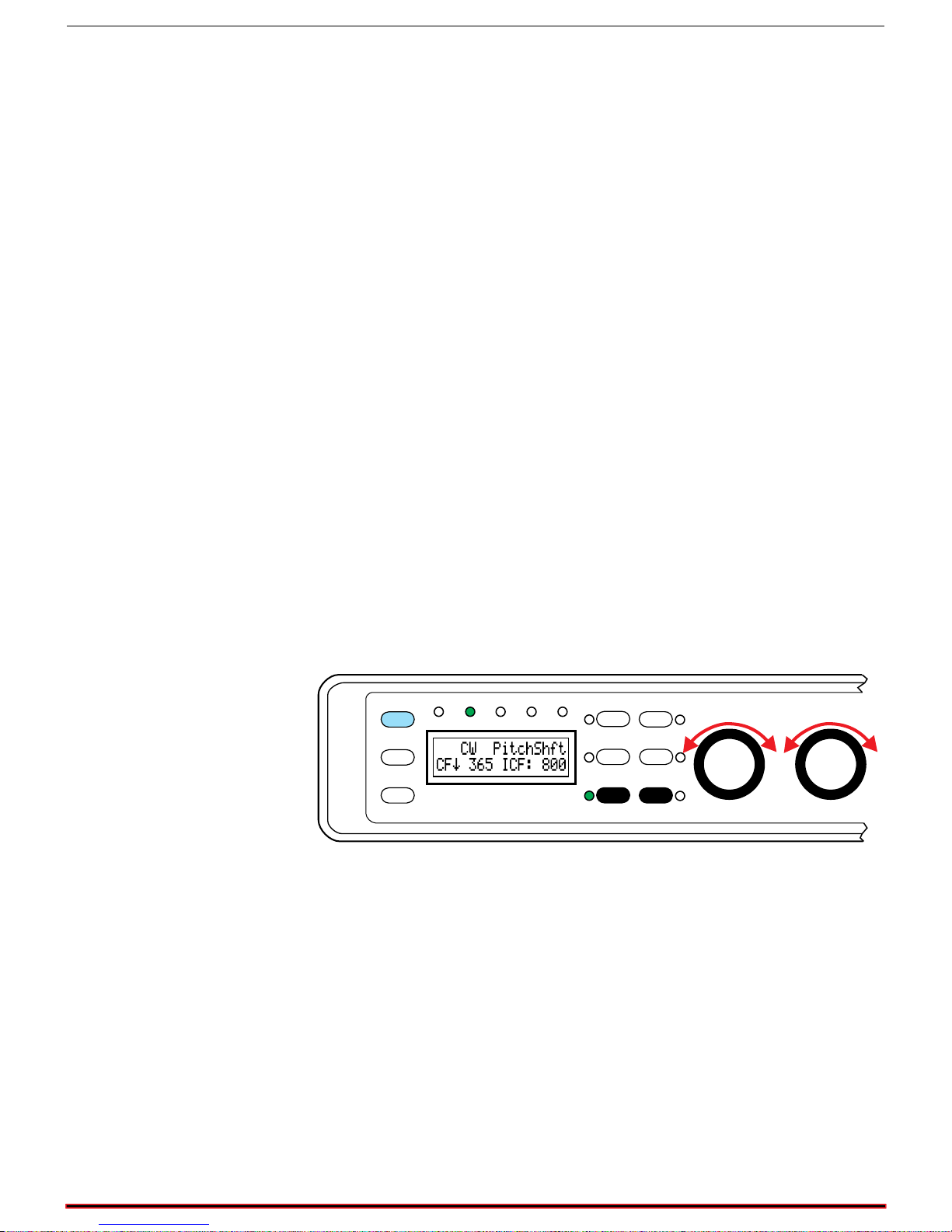
CW Tone Pitch Shift
A feature unique to the DSP-599zx is the ability to ea sily s hift t he CW t one
pitc h t o a nother f r equency. This fea t ure works well wit h r ec eivers t ha t ha ve
non-adjustable, relatively high pitch CW tone, since most hams prefer to
listen to 400 - 600 Hz CW tones.
1
Mode
Spkr/Chan
Rcl/Store
Voice
Data
CW
DSP-599zx
Test
Setup
Bypass
3
AGC
5
Shift
2
Tone
4
Random
6
Function
Timewave
High Pass
Center Freq
Low Pass
Bandwidth
599-014
Features Version 1.1 16
Page 17
Data Mode
The Da ta Mode digit ally p roc esses dat a s ignals inclu ding RTTY, AM TOR ,
PacTOR, G-TOR, CLOVER HF packet, SSTV and WeFAX. I ndep endent ly
selecta ble pr ocessing techniques include noise reduction, tunable bandpass
filter ing and automatic gain c ontrol, and a sp ecial RTT Y modem and RTTY
remodula tor.
Mode
Spkr/Chan
Rcl/Store
Timewave DSP-599zx Audio Noise Reduction Fi lter
1
Voice
Data
CW
DSP-599zx
Test
Setup
Bypass
3
AGC
5
Shift
2
Tone
4
Random
6
Function
Time
High Pass
Center Freq
599-029
Bandpass Filters
The DSP-599zx has both fixed and tunable bandpass filters for the data
mode. Nar row b and F SK si gnals like RTT Y requir e a b andpa ss filter with
steep s kir t s, linea r p ha se r esp ons e, a nd mat ched a mplitu de r es pons e. L inear
phas e respons e max imizes the usa ble signaling rat e for a given ba ndwidth
and minimizes r inging often hear d on extr emely shar p f ilters . T he mat ched
amplitude response tailors the filter to match the selected modulation type
and b aud rat e to minimize noise and interfering signals.
The DSP-599zx also has fixed frequency matched ba ndpass filters centered
at 2210 Hz as well as lower frequencies for European standards and 16001800 Hz HF packet. The selectable bandwidths of the bandpass filters
provide optimum filtering for 170 Hz and 200 Hz frequency shift data
signa ls of va rious baud rates.
The DSP-599zx has individual linear phase fixed bandpass filters with
steep skirts for SSTV, WeFAX and CLOVER. Since the bandwidths for
these modes are fixed, the filters are primarily QRM filters for adjacent
channel signals rather than noise reduction filters for eliminating random
noise. T he S S T V f ilter is a dual pa s s ba nd filt er with one p a s sb a nd cent ered
on the SSTV sync pulse at 1200 Hz, and the other passband around the
varying FM picture tones from 1500-2300 Hz. WeFAX is similar to SST V
but has no separate sync pulse so the filter bandpass covers 1500-2300 Hz.
The CLOVER filter has a 500 Hz bandwidth with a center frequency of
2250 Hz.
Features Version 1.1 17
Page 18
Timewave DSP-599zx Audio Noise Reduction Fi lter
Data Tuning Function
Mode
Spkr/Chan
Rcl/Store
Voice
Data
CW
DSP-599zx
Test
Setup
1
Bypass
3
AGC
5
Shift
2
Tone
4
Random
6
Function
Timewave
High Pass
Center Freq
Low Pass
Bandwidth
599-057
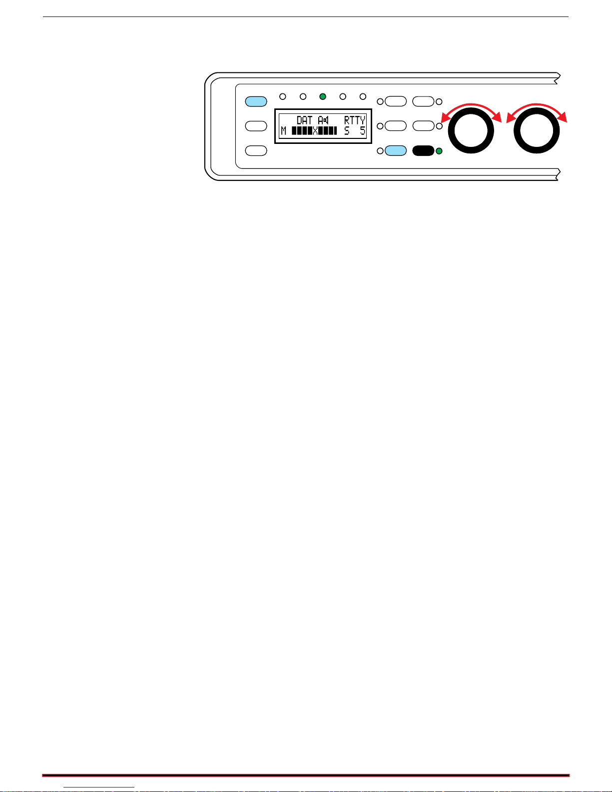
Pressing
[Shift+Function]
turns the tuning display on. This display
pr ovides inf ormation gra phically to allow p recise tuning of the receiver. The
display also shows the strength of the incoming data signal.
Random Noise Reduction
The DSP-599zx random noise reduction function is not specifically
designed for dat a signals, but has been field pr oven to be useful for nois e
reduc tion under s ome conditions. I t is u sua lly most effective for 45. 5 b aud
RTTY signals.
RTTY Modem
The DB-9F connector provides an RS-232 compatible connection for the
RTTY modem outp ut t o a compu t er. T he out pu t is demodula t ed F S K in t he
same code format (Baudot, ASCII, etc.) as the received signal. It is not
decoded or changed in any way except for demodulation. The AFSK
modulat ed ou tpu t for the tr ansmitter appears on the line output c onnector of
the selected channel. The channel is selectable within setup. The PTT
outp ut signa l needed to put your tr a nsceiver in tr ans mit mode is pa r t of t he
DIN c onnector f or the appropriate channel.
The AFSK output is a modulated AFSK signal in the same code format
(Baudot, ASCII, etc.) as the keying signa l from the computer. The DSP599zx does not encode or change the signal in any way except for AFSK
modulation. A software terminal program that can decode and encode
Bau dot a nd ASC II c ode needs to b e insta lled on t he compu ter connect ed t o
the DSP-599zx. Timewave does not provide the terminal program. This
modem is for RTTY operation only with signa ling ra tes a t 75 B aud or less.
This modem featu re is designed for RTTY oper ation. It is not des igned to
be used as a TNC.
Features Version 1.1 18
Page 19

Timewave DSP-599zx Audio Noise Reduction Fi lter
RTTY Remodulator
The DSP-599zx has another special data function for RTTY only. After
passing through the optimized RTTY bandpass filter, a precision DSPbased FSK detector in the DSP-599zx demodulates the noisy incoming
RTTY t ones and us es the recovered digit al dat a to dr ive a pr ecision DS Pbased AFSK generator. This remodulation process takes place entirely in
the DSP-599zx. The precise clean tones from the RT TY AFSK remodulator
can feed any analog multimode controller or TU via the DSP-599zx line
au dio ou tpu t.
Many analog RTTY demodulators have difficulty with noisy signals of
var ying amplitu de, but virt ually a ll of them can a dequat ely demodulate the
precise DSP AFSK generator output. The
[Function]
push-button selects
either the remodulator with RTTY filters or the RTTY filters only. This
remodula tor is opti mized for non-b u rst data at 7 5 Bau d or less .
RTTY FSK Test Signals
Press
[Tone]
while in the non burst Data mode a t 75 bau d or les s activates
a sync nul (diddle) test tone. If the baud rate is 100 baud or higher, pressing
[Tone ]
Pressing
activates a space mar k reference calibration tone.
[Shift+Tone]
while in the
Data
RTTY mode at 75 baud or less
insert s a n a udio FS K t est signa l into t he receive cha nnel. T he “ RYRY” t est
signal is centered a t 2210 Hz with a frequency shift of +/- 85 Hz. The ba ud
rate is determined by the RTTY parameter settings. The level of marker
tone is a djus t a b le rela t ive to t he pr oces sed r eceive signa l. If the baud rate is
100 baud or higher, nothing happens when
[Shift+Tone]
is pressed
.
Features Version 1.1 19
Page 20
Timewave DSP-599zx Audio Noise Reduction Fi lter
Test Instrument Mode
The Test I nstr ument func tion helps a nalyze s ignals a nd other equipment. I t
includes an audio millivoltmeter, an audio signal generator, and an audio
tone decoder.
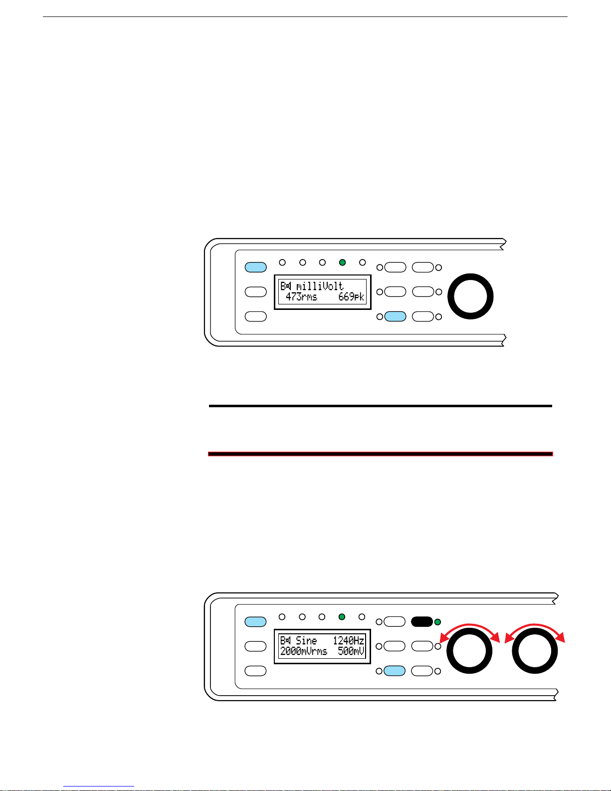
Audio Millivoltmeter
This mode measures audio voltage levels from other equipment including
microphones, TNCs, multimode controllers, and receivers. Measurements
ar e bot h p eak a nd t r u e RM S millivolts . F r equency r esp ons e r a nges f r om 2 0
Hz to 10 kHz. In EME work, the audio millivoltmeter mode is useful in
ant enna evalu ation when comparing sun nois e and cold sky nois e.
Voice
Mode
CW
1
TestData
Setup
Bypass
2
Tone
3
4
Time
! !
Maximum input level is 2000 millivolts rms.
Do not attempt to measure any voltage above 2000 millivolts,
especially 115 Vac or 220 Vac power line voltage! You will
damage the DSP-599zx! ALL WARRANTIES WILL BE VOID!
Audio Signal Generator
This mode produ ces tunable low-dist ortion, p recision fr equency sine wave
test signals fr om 20 H z to 10 kHz in 10 Hz steps. A two-tone test signal
may be selected for SSB testing. The operator may use the precision test
signa ls for ca libra tion and/ or tr ouble shooting of other equipment t he user
may own. The display shows the frequency and amplitude of the output
signa l f rom the line output.
Spkr/Chan
Rcl/Store
DSP-599zx
AGC
Shift
Random
5
6
Function
High Pass
Center Freq
599-081
Features Version 1.1 20
Mode
Spkr/Chan
Rcl/Store
Voice
Data
CW
DSP-599zx
Test
Setup
1
Bypass
3
AGC
5
Shift
2
Tone
4
Random
6
Function
Timewave
High Pass
Center Freq
Low Pass
Bandwidth
599-046
Page 21
Timewave DSP-599zx Audio Noise Reduction Fi lter
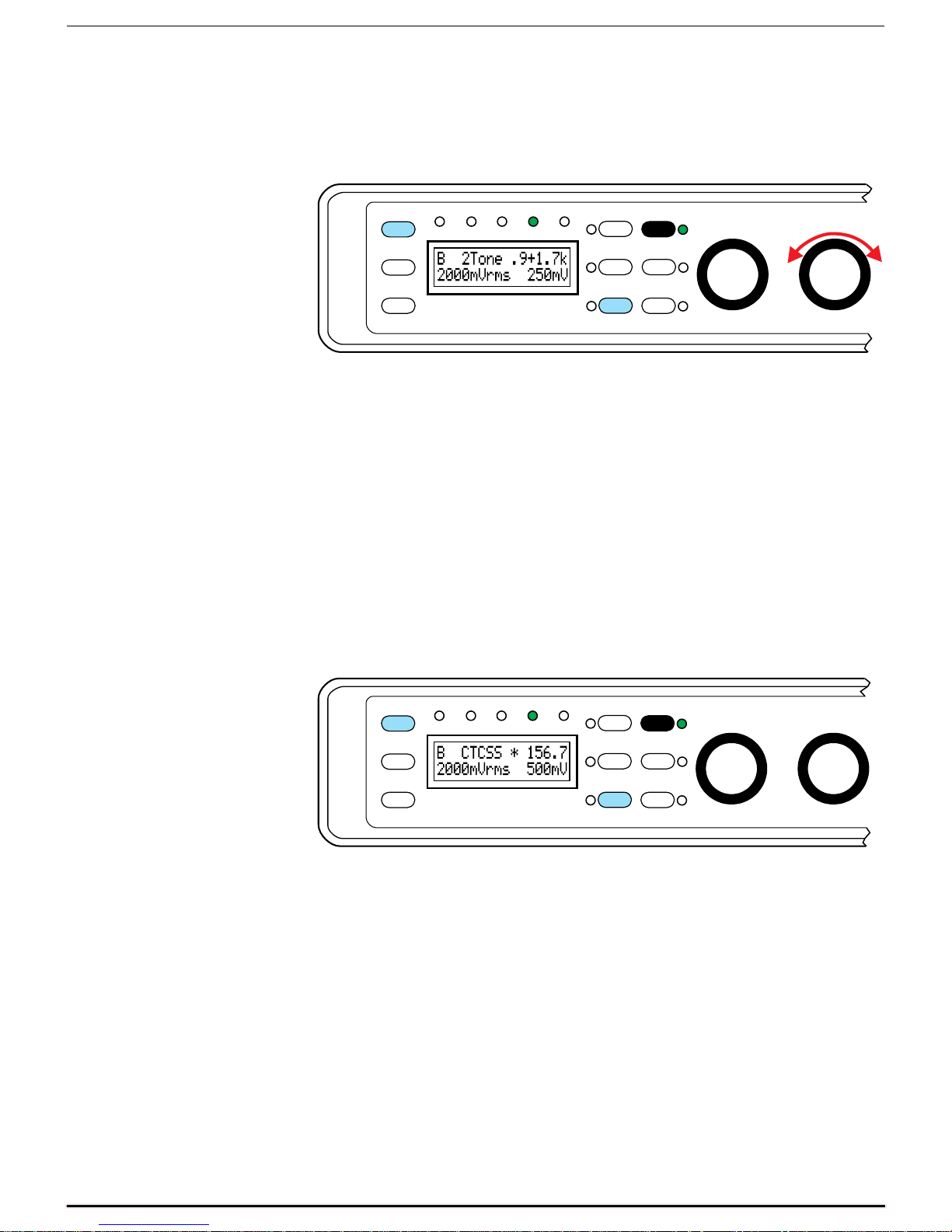
Two-Tone Generator
Pr oduces a two-t one signa l that ca n be used for S SB linear ity test ing. The
DSP-599zx produces a very pure tone set. This provides for very accurate
test ing.
1
Mode
Spkr/Chan
Rcl/Store
Voice
Data
CW
DSP-599zx
Test
Setup
Bypass
3
AGC
5
Shift
2
Tone
4
Random
6
Function
Timewave
High Pass
Center Freq
Low Pass
Bandwidth
599-047
CTCSS Tone Decoder
This mode decodes CTCSS tones. The CTCSS function shows the tone
frequency and amplitude on the LCD display. There are two modes of
operation. The fi rst is the aut odet ect mode which displays the frequency and
amplitude of any valid CTCSS tone received. The second is the tone
squelch mode which detects a select ed CTCS S tone a nd activa tes a s witch
output on the DSP-599zx as well as generates a tone on the selected
CTCSS frequency. The audio millivoltmeter function displays the peak
amplitude of the selected incoming CTCSS tone. This allows relative
measurement of peak deviation of CTCSS tones and voice for UHF and
VHF FM/PM transmitters.
Mode
Spkr/Chan
Rcl/Store
Voice
Data
CW
DSP-599zx
Test
Setup
1
Bypass
3
AGC
5
Shift
2
Tone
4
Random
6
Function
Timewave
High Pass
Center Freq
Low Pass
Bandwidth
599-054
Features Version 1.1 21
Page 22

Timewave DSP-599zx Audio Noise Reduction Fi lter
DSP-599zx Specifications
AUDIO INPUT A & B
Impedance 20 K ohms or 25 ohms, jumper selectable
input signal range for full
output
AUDIO OUTPUT A & B
Speaker output power 1.0 watts into 8 ohms at 13.8 VDC, both output channels A & B operating,
Line Output -3 dBV to -24 dBV referenced to input level. Adjustable within setup.
Headphone Jack 1/4” two-circuit jack, use stereo headphones to use all functions, mono headphones for most functions
Harmonic Distortion less than 1% at rated output
NOISE REDUCTION FILTERS
Random Noise Reduction entire freq. range of selected
Heterodyne Eliminator
(multiple automatic notch)
Heterodyne Eliminator
(manual notch)
Note: The random noise reduction and bandpass filters can operate simultaneously.
10 mV to 1.0 volt, front panel programmable
1.5 watts into 4 ohms at 13.8 VDC, both output channels A & B operating,
Frequency Range Attenuation Type Delay
Up to 20 dB, varies with noise characteristics.
filter
entire freq. range of selected
bandpass filter
entire freq. range of selected
bandpass filter
The random noise reduction, tone notch and highpass/lowpass filters can operate simultaneously.
Noise reduction aggressiveness front panel
adjustable
Up to 50 dB, varies with noise characteristics Adaptive 5 msec max
Up to 50 dB, varies with noise characteristics manual
Adaptive 5 msec max
CW FILTERS
CW filters Bandwidth = 5 Hz to 600 Hz, 10
CW Marker Tone Sine wave at center freq. of selected CW filter.
DATA FILTERS
,
RTTY
PACTOR,
G-TOR,
HF Packet
Note: RTTY and AMTOR filters have a notch at the center frequency .
CLOVER 2000-2500 Hz 55 dB at 75 Hz outside the passband FIR Linear
SSTV 1100-1300 Hz & 1500-2300
WeFAX 1500-2300 Hz 55 dB at 75 Hz outside the passband FIR Linear
FSK Marker
Tones
AMTOR,
Hz steps.
Center freq. = 200 to 2150 Hz,
5 Hz steps,
Mark/Space bandwidth 60 Hz
to 100 Hz, Center Freq.= 2210
Hz plus options of 1700, 1360,
1300, 1530 or 2125 Hz
Hz
RY string
1)
matches selected RTTY data mode.
Sync-Nul Character (Diddle)
2)
- Alternating sine waves at mark-space freq. of selected data filter (170 or 200 Hz shift). Baud rate
55 dB at 60 Hz outside the passband FIR Linear
phase
40 dB at 60 Hz outside the passband FIR Linear
phase
phase
50 dB at 75 Hz outside the passband Composite
FIR Linear
phase
phase
- Baud rate matches selected data filter.
BW less
than 20
Hz=64
msec max
BW greater
20 Hz=40
msec max
38 msec
max
21 msec
max
21 msec
max
21 msec
max
Features Version 1.1 22
Page 23

RTTY MODEM
Shifts 170, 200, 425, 850 Hz
Data Rates 45, 50, 57, 75 Baud
Input Audio from receiver.
Output Open collector FSK and variable level AFSK
Transmit Data
Polarity
I/O Receive data, Transmit data, PTT (RS-232 compatible)
VOICE FILTERS
Highpass Corner freq. = 100 to 1000 Hz,
Lowpass Corner Freq. = 1000 to 5000 Hz,
AGC
Voice mode 36 dB
CW and Data Modes 18 dB
Timewave DSP-599zx Audio Noise Reduction Fi lter
Normal or Reverse
Frequency Range Attenuation Type Delay
10 Hz steps.
10 Hz steps.
60 dB at 180 Hz
outside the passband
60 dB. at 180 Hz
outside the passband
FIR Linear phase 24 msec max for any
combination of
FIR Linear phase highpass & lowpass
SIGNAL PROCESSING
A-D/D-A Converter 16 bit linear, sigma-delta conversion, dual channel
Signal Processor 16 bit, 27 ns Analog Devices ADSP-2181 with 80 KB of memory
TEST INSTRUMENT MODE
Audio
Generator
Audio millivoltmeter
CTCSS
encoder decoder
CTCSS
squelch
Single or two-tone. single Sine wave tunable from 20 Hz to 10 kHz.
Two-tone fixed 700 Hz and 1900 Hz.
Sine wave distortion less than 1%.
True RMS from 4 mV to 2000 mV., 20 Hz to 10 kHz
Generates and decodes and displays CTCSS “PL” tones from 67.0 Hz to 254.1 Hz.
Open collector output pulls low when selected CTCSS tone is present. (connection on back panel DIN connector)
MEMORY
Six Memories All configuration setups can be stored and recalled (except volume control setting).
DISPLAY
2x16 alphanumeric characters, dot-matrix, yellow-green backlit LCD.
DIMENSIONS
Size 7.6 in. wide x 8.5 in. deep x 1.9 in. high (193 mm wide x 216 mm deep x 48 mm high)
Weight 2.53 lb. (1.15 Kg.)
POWER
Requirements 12-16 VDC @ 1A
Fuse 1.6A 5 mm x 20 mm
Note:
dB points to comply with traditional da ta filter specification methods. All other filter bandwidths are
specified to comply with conventional DSP FIR filter parametric descriptions.
Features Version 1.1 23
RTTY, AMTO R, PacTOR, G-TO R and HF Packet data filter bandwidths are specified at -3
 Loading...