

Page 1

Timewave Technology Inc.
1025 Selby Ave, suite 101
St. Paul, MN 55104, USA
(651) 489-5080
http://www.tmewave.com
DSP-232
Multi-Mode
Operating Manual
Page 2

DSP-232 Multi-Mode Operating Manual
Welcome
Thank you for purchasing a Timewave product! Before you go any further, please fill out and return the enclosed
Warranty Registration Card. Only a portion of all warranty cards are return, which makes it hard to keep
customers up to date. From time to time,
updates if we have your warranty card on file, so send it in if you haven’t already done so. Returning your warranty
card also places you on
FCC Regulations
This device complies with Part 15 of the FCC rules. These rules are designed to provide reasonable protection
against harmful interference in a residential installation. This device generates, uses, and can radiate radio frequency
energy and, if not installed and used in accordance with the instructions, may cause harmful interference to radio
communications. However, these is no guarantee that interference will not occur in particular installation. If this
device does cause harmful interference to radio or television reception, which can be determined by turning the
device on and off, the user is encouraged to try to correct the interference by one or more of the following measures:
• Reorient or relocate the receiving antenna.
• Increase the separation between the device and receiver.
• Connect the device into an outlet on a circuit different from that to which the receiver is connected.
• Consult the dealer or an experienced radio/TV technician for help.
Changes or modifications not expressly approved b y th e manufacturer will void the user’s authority to operate the
device.
You must use shielded cables for all device connections, then tie all grounding wires/shields to a single point,
normally the radio. You need an effective station ground or you’ll have problems when RFI infiltrates your
equipment and causes all kinds of unexpected problems.
Disclaimer
As part of its continuing program of product improvement, AEA reserves the right to make changes in this
product’s specifications or documentation. AEA also reserves the right to incorporate and issue any information
thus supplied in whatever manner it deems suitable, without incurring any obligation whatsoever.
Copyright
© 1995, 2005 by Timewave Technology Inc. All rights reserved.
Under copyright laws, this manual can not be reproduced in any form without prior written permission from Timewave Technology
Inc. No patent liability is assumed, however, with respect to the use of the
information contained herein.
This manual may contain errors, omissions or “typos.” Please send your comments, suggestions, and corrections to: Timewave
Technology Inc., 1025 Selby Ave, Suite 101, St. Paul, MN 55104
Timewave’s catalog mailing list.
Timewave
Timewave offers updates to its products--we can only tell you about these
Table of Contents
ii September, 05
Page 3

DSP-232 Multi-Mode Operating Manual
FCC Regulations ................................................................................................................................ii
Chapter 1 - DSP-232
Capabilities .....................................................................................................................................1-1
What did & didn’t come in the box ..................................................................................................1-2
A Tour of the DSP-232....................................................................................................................1-3
The Front ................................................................................................................................1-3
Mode Indicators ......................................................................................................................1-3
Status Indicators.....................................................................................................................1-5
Other Indicators ......................................................................................................................1-6
The Back.................................................................................................................................1-7
Chapter 2 - Power Supply and Computer Installation
Connecting Power...........................................................................................................................2-1
Turning it On ...................................................................................................................................2-1
Re-Initialization ...............................................................................................................................2-2
Connecting Your Computer to the DSP..........................................................................................2-2
The Cable ...............................................................................................................................2-2
Peripherals and IRQ Conflicts ................................................................................................2-4
The Control Program..............................................................................................................2-4
System Start-up and Loop-back Tests ...........................................................................................2-6
Radio Port 1 Test....................................................................................................................2-6
Radio Port 2 Test....................................................................................................................2-8
Chapter 3 - Radio Installation
Radio Connection Requirements....................................................................................................3-1
Connections for Specific Transceiver Models ................................................................................3-2
Basic Connections and Adjustments..............................................................................................3-2
Connections for Direct FSK on RTTY.....................................................................................3-4
Transceiver Adjustments ................................................................................................................3-4
FM Transceiver Adjustments..................................................................................................3-5
SSB Transceiver Adjustments................................................................................................3-7
Chapter 4 - Terminal Commands
Command Mode .............................................................................................................................4-1
Converse Mode...............................................................................................................................4-1
Transparent Mode...........................................................................................................................4-2
Host Mode.......................................................................................................................................4-2
Kiss Mode .......................................................................................................................................4-2
Parameters and Arguments............................................................................................................4-2
List of General and Terminal Related Commands .........................................................................4-3
Complete DSP-232 Command List.................................................................................................4-29
Chapter 5 - Packet Operation
Switching Between Radio Ports......................................................................................................5-1
Tuning in Packet Stations VHF/UHF ..............................................................................................5-2
What it Means.........................................................................................................................5-5
Who’s Out There?...................................................................................................................5-6
Talking to Yourself..........................................................................................................................5-7
Connecting..............................................................................................................................5-7
CTEXT....................................................................................................................................5-8
Setting Up for Transmitting.............................................................................................................5-8
Calling CQ.......................................................................................................................................5-8
September, 05 iii
Page 4

DSP-232 Multi-Mode Operating Manual
Going on the Air......................................................................................................................5-9
I’m having Trouble Connecting...............................................................................................5-9
More Packet Features.....................................................................................................................5-10
Nodes and Node Operation....................................................................................................5-10
Your DSP acts as a Node!..............................................................................................................5-10
Operating Your Node..............................................................................................................5-11
Digipeating..............................................................................................................................5-13
Are Your a Digipeater?...........................................................................................................5-13
Identifying as a Digipeater......................................................................................................5-14
Time-stamping Packet Messages ..........................................................................................5-14
Multiple Connection Operation .......................................................................................................5-14
Setting Up...............................................................................................................................5-14
The Channel Switching Character..........................................................................................5-14
CHCALL..................................................................................................................................5-15
HF Packet Operation ......................................................................................................................5-15
Where to Operate...................................................................................................................5-15
Settings...................................................................................................................................5-16
Tuning in HF Packet Stations.................................................................................................5-16
Transmitter Adjustments.........................................................................................................5-16
Going on the air ......................................................................................................................5-16
Packet Meteor Scatter Extension ...................................................................................................5-17
Immediate and Advanced Packet Commands ...............................................................................5-18
Packeting Through Voice Repeaters..............................................................................................5-19
Packet Formatting and Editing........................................................................................................5-19
Packet Protocol Basics...................................................................................................................5-20
Packet Mail......................................................................................................................................5-23
Packet Commands..........................................................................................................................5-23
Chapter 6 - Global Positioning System Applications
Why do GPS in the DSP-232?........................................................................................................6-1
What is APRS? ...............................................................................................................................6-1
Hardware Configurations................................................................................................................6-2
Setting Up the DSP-232 for GPS Operation...................................................................................6-3
Stand Alone Tracking Device Set Up.....................................................................................6-4
Connecting the GPS Receiver to the DSP-232..............................................................6-5
Hardware Single Port Mode....................................................................................................6-5
Dual Port Mode Set Up...........................................................................................................6-6
Building your own APRS cable.......................................................................................................6-6
Schematic Diagram for the APRS Adapter Cable..................................................................6-7
DSP-232/ULTIMETER II Stand Alone Weather Set Up .................................................................6-7
GPS Specific Commands ...............................................................................................................6-8
Chapter 7 - MailDrop Operation
MailDrop Memory............................................................................................................................7-1
Expanding Your MailDrop...............................................................................................................7-2
Setting Up Your MailDrop...............................................................................................................7-2
Accessing and Commanding Your MailDrop..................................................................................7-2
Monitoring Your MailDrop...............................................................................................................7-3
Packet MailDrop Prompts and Operation.......................................................................................7-3
Packet MailDrop command summary.....................................................................................7-3
Sending Mail ...................................................................................................................................7-5
Sending Other Types of Messages........................................................................................7-6
Message Numbers..................................................................................................................7-9
Forwarding and Reverse-Forwarding.....................................................................................7-9
Settings for Auto-forwarding...................................................................................................7-9
Entering a Message for Reverse Forwarding.........................................................................7-9
AMTOR MailDrop............................................................................................................................7-10
iv September, 05
Page 5

DSP-232 Multi-Mode Operating Manual
Command Definitions for AMTOR..........................................................................................7-11
PACTOR MailDrop..........................................................................................................................7-12
Command Definitions for PACTOR........................................................................................7-12
MailDrop Commands......................................................................................................................7-13
Chapter 8 - ASCII and BAUDOT Operation
Setting Up for ASCII........................................................................................................................8-1
Setting Up for BAUSDOT................................................................................................................8-2
Receiving ASCII & BAUDOT ..........................................................................................................8-2
Going on the Air..............................................................................................................................8-3
Calling CQ.......................................................................................................................................8-3
Answering a CQ..............................................................................................................................8-4
The QSO ........................................................................................................................................8-4
Roundtable QSOs and Nets...........................................................................................................8-4
Operating Tips and Options............................................................................................................8-5
BAUDOT and ASCII Commands....................................................................................................8-7
Chapter 9 - AMTOR Operation
Setting Up .......................................................................................................................................9-2
Receiving AMTOR..........................................................................................................................9-2
Going on the Air..............................................................................................................................9-3
Calling CQ...............................................................................................................................9-4
Answering Another Station’s CQ............................................................................................9-4
Beginning a QSO....................................................................................................................9-4
Ending a QSO.........................................................................................................................9-4
Seizing the Link ......................................................................................................................9-5
Killing the Link.........................................................................................................................9-5
Roundtable QSOs...........................................................................................................................9-5
“Hidden” QSOs ...............................................................................................................................9-5
Operating Tips and Options............................................................................................................9-6
MailDrop Operation.........................................................................................................................9-7
LED Status and Mode Indicators....................................................................................................9-8
AMTOR Commands........................................................................................................................9-10
Chapter 10 - Morse Operation
Special Morse Characters ..............................................................................................................10-1
Setting Up .......................................................................................................................................10-1
Tuning in Morse Stations................................................................................................................10-2
Going on the Air..............................................................................................................................10-2
Calling CQ...............................................................................................................................10-2
Operating Tips ................................................................................................................................10-3
Type Ahead Buffer..................................................................................................................10-3
Operating QSK........................................................................................................................10-3
Morse Commands...........................................................................................................................10-4
Chapter 11 - SIAM and NAVTEX Operation
Setting Up for SIAM........................................................................................................................11-1
Reception........................................................................................................................................11-2
Copying Encoded RTTY Transmissions.........................................................................................11-2
About NAVTEX ...............................................................................................................................11-3
Setting Up for NAVTEX...................................................................................................................11-3
Receiving NAVTEX Signals............................................................................................................11-3
SIAM and NAVTEX Commands .....................................................................................................11-4
Chapter 12 - PACTOR Operation
Setting Up .......................................................................................................................................12-2
September, 05 v
Page 6

DSP-232 Multi-Mode Operating Manual
Receiving PACTOR........................................................................................................................12-2
Going on the Air..............................................................................................................................12-3
Roundtable QSOs...........................................................................................................................12-4
Calling CQ...............................................................................................................................12-4
Answering Another Station’s CQ............................................................................................12-4
Beginning a QSO....................................................................................................................12-4
Ending a QSO.........................................................................................................................12-5
Killing the Link.........................................................................................................................12-5
Seizing the Link ......................................................................................................................12-5
File Transfers..................................................................................................................................12-5
MailDrop Operation.........................................................................................................................12-5
Operating Tips and Options............................................................................................................12-6
Status and Mode Indicators............................................................................................................12-7
PACTOR Commands ....................................................................................................................12-8
Chapter 13 - Troubleshooting
A Troubleshooting Primer...............................................................................................................13-1
Power Supply..........................................................................................................................13-2
Power Supply Cable...............................................................................................................13-2
The DSP-232..........................................................................................................................13-2
Cable from the DSP-232 to Computer....................................................................................13-2
Computer/Software.................................................................................................................13-2
Cable from DSP-232 to Radio................................................................................................13-2
Radio.......................................................................................................................................13-3
General Error Messages.................................................................................................................13-4
Packet Error Messages ..................................................................................................................13-5
MailDrop Error Messages...............................................................................................................13-7
DSP-232 Status and Error Messages.............................................................................................13-7
Out of the Box Problems.................................................................................................................13-9
Computer to DSP-232 Problems....................................................................................................13-9
Radio to DSP-232 Problems...........................................................................................................13-10
Morse Problems..............................................................................................................................13-10
ASCII/BAUDOT Problems ..............................................................................................................13-11
SIAM Problems...............................................................................................................................13-12
MailDrop Problems .........................................................................................................................13-13
Packet Problems.............................................................................................................................13-14
AMTOR & PACTOR Problems .......................................................................................................13-17
DSP-232 Problems.........................................................................................................................13-19
Index
Appendix A - Specific Radio Connections
Radio Connection Notes.................................................................................................................A-1
Radio List A-2
Radio Connection Figures..............................................................................................................A-6
Appendix B - Specifications
Appendix C - Limited Warranty
Appendix D - 256K RAM upgrade
Appendix E - Schematics and Pictorial
vi September, 05
Page 7

Chapter 1 The DSP-232
Chapter 1
The DSP-232
Overview
The DSP-232 was designed by Timewave Technology Inc. to be the ultimate digital operating platform
when coupled to your computer or “dumb” terminal. The DSP couples your HF, VHF, UHF transceiver(s) or shortwave receiver to your computer so you can “talk” to other Amateurs or listen in to their—or a utility station’s—
digital and Morse communications. This unit is state-of-the-art and has been designed with an eye toward the future.
The architecture and parts used in the DSP-232 allow room for future technological enhancements.
232MBX left a decade long legacy of dependability and high-performance digital communication, the DSP-232 will
carry you through the next decade, and well into the next century.
Capabilities
With the DSP you can transmit and receive all the popular amateur digital modes. You can receive other modes
such as NAVTEX and bit-inverted Baudot RTTY. These capabilities, along with SIAM (Signal Identification and
Acquisition Mode), make the DSP ideal for the digital signal short-wave listeners (SWL) as well as the active
digital communication users. New modes will become popular and you can be assured this unit will be able to
handle them.
The DSP will transceive in the following modes:
♦ AX.25 packet on HF (300 bps), VHF and UHF (9600 bps and 1200 bps)
♦ Baudot and ASCII RTTY
♦ AMTOR/SITOR CCIR Rec. 476 and 625
♦ Morse Code
♦ PACTOR
In addition, the DSP receives the following modes:
♦ NAVTEX marine broadcasts and AMTEX amateur bulletins
♦ Bit-inverted Baudot RTTY
The DSP also has the following special features:
♦ Gateway firmware which allows the DSP-232 to operate as a node and identify TCP/IP, TheNet, and
NET/ROM stations. There are two heard lists with Gateway, one for nodes heard and one for stations heard.
♦ Memory ARQ for better HF throughput in marginal conditions.
DSP-232 features continued. . .
Timewaves’s PK-
September, 05 1-1
Page 8

Chapter 1 The DSP-232
♦ Numerous external adjustments, ports, and connectors.
♦ The ultimate in digital filtering with the high-power, high-speed Digital Signal Processor.
♦ The unique LED display wh ich keeps you informed of system activity. This display allows for future modes
and features as no other display can. After all, we designed this unit for growth.
♦ Packet/AMTOR/PACTOR MailDrop message handling.
♦ A Mailbox that can expanded to 242K (256K RAM).
♦ KISS mode for TCP/IP packet applications.
♦ Host mode for popular Host application programs.
What Did—and Didn’t—Come In the Box
Besides this manual, the following items are enclosed:
♦ two 5-pin DIN radio cable
♦ one 8-pin DIN connector
♦ two RX audio cables
♦ one 2.1mm power cable
♦ one wire loop-back jumper
♦ an RS-232 serial cable with DB-9 connectors (pins 1-3 and 5-8 connected)
Here’s what isn’t enclosed:
♦ DOS, MacIntosh, or other computer platform software to operate your DSP
♦ microphone connectors for your radio(s)
♦ a power supply
♦ a computer and a radio!
The DSP will work with practically any telephone modem or terminal emulation program that your computer can run
as long as it uses the full ASCII character set. However, PK-Term for Windows is powerful
programs offered by CSS that istailor-made for its controller products. These programs offer many operating and
utility features—and conveniences—that simply aren’t found in typical modem and 3rd party controller programs.
But, if you do run Windows, PK-Term for Windows is the best amateur radio
has to offer in Windows control software. Visit http;//www.cssincorp.com
for more details about PK-Term programs.
We also didn’t enclose any mike connectors because we don’t know which brand or model of radio you plan to use
with your DSP.
Finally, we didn’t include a power supply since many owners simply connect their DSP to the same 12 VDC supply
that powers their radio and station accessories. If you want to operate your DSP from a “power cube” that plugs into
your wall outlet, you can purchase one locally or you can purchase the AC-5 power supply from Timewave
or through your favorite electronic equipment dealer.
Your Radio...
We presume that you have an operating radio transceiver or short-wave receiver that you’ll use with your DSP. In
the Amateur bands, most of the VHF packet activity occurs on the 2-meter FM band while most of the HF digital
activity occurs on the 20-meter band. By convention, an HF receiver or transceiver must be capable of SSB
operation in order to communicate digitally to other stations. While no specific brand of transceiver is required, we
recommend that a modern transceiver (built in the last 20 years) be used. Specific transceiver connections are
described in Appendix A of this manual.
1-2 September, 05
Page 9
Chapter 1 The DSP-232
Most modern radio transceivers are capable of excellent performance in Morse, Baudot and ASCII RTTY,
AMTOR, PACTOR, and packet radio. Although AMTOR Mode A (ARQ) and PACTOR operation imposes more
demanding switching speed requirements than the other operating modes, most radios will operate in both AMTOR
and PACTOR modes without any modifications. (See the AMTOR operating section for further details on timing
requirements.) The DSP has software-controlled timing variations that permits operation with nearly all the HF,
VHF and UHF radios in general use today.
...and Computer
You’ll need a computer or “dumb” terminal that has an RS-232 serial communications port in order to have it
communicate with your DSP. The most popular computers are IBM™-PC compatibles, PC laptops, and Apple
Macintosh™ (and Powerbooks™).
For the sake of brevity in this manual, instead of using both the phrases “dumb terminal” and “computer”
interchangeably we’ll just use the word, computer.
A Tour of the DSP-232
Before you leap ahead into the next chapter to see how to hook up your DSP, you should read this section to find
out what all those LEDs, adjustment levels and connectors are on the unit and what they do. If their functions or
terms sound cryptic to you now, don’t worry about it—they’ll be explained fully in later chapters.
Carefully remove the DSP from its box and plastic bag and inspect the it for signs of damage that may have
occurred during shipment. If there’s visible damage, please contact the dealer or shipper. Don’t install or use a
damaged controller.
The Front
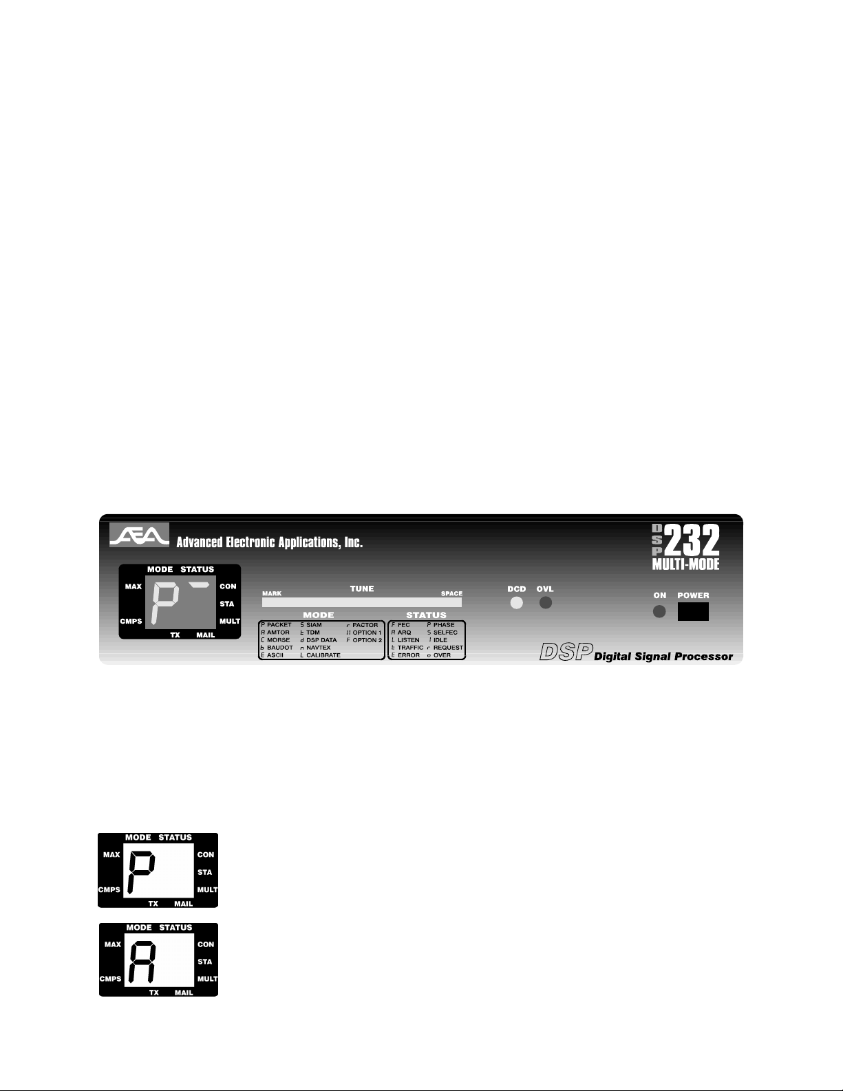
Front view of the DSP-232
Now, set it on the table or hold it in your hands and take a few minutes here to take a guided tour of your controller,
starting with the blacked-out display on the left-hand side of the front of the DSP labeled Mode and Status. Under
this black display are two, seven-segment LED indicators. These lights tell you which mode you’re using and
what’s going on while you’re in that mode. Let’s start with the ones in the MODE box.
Mode Indicators
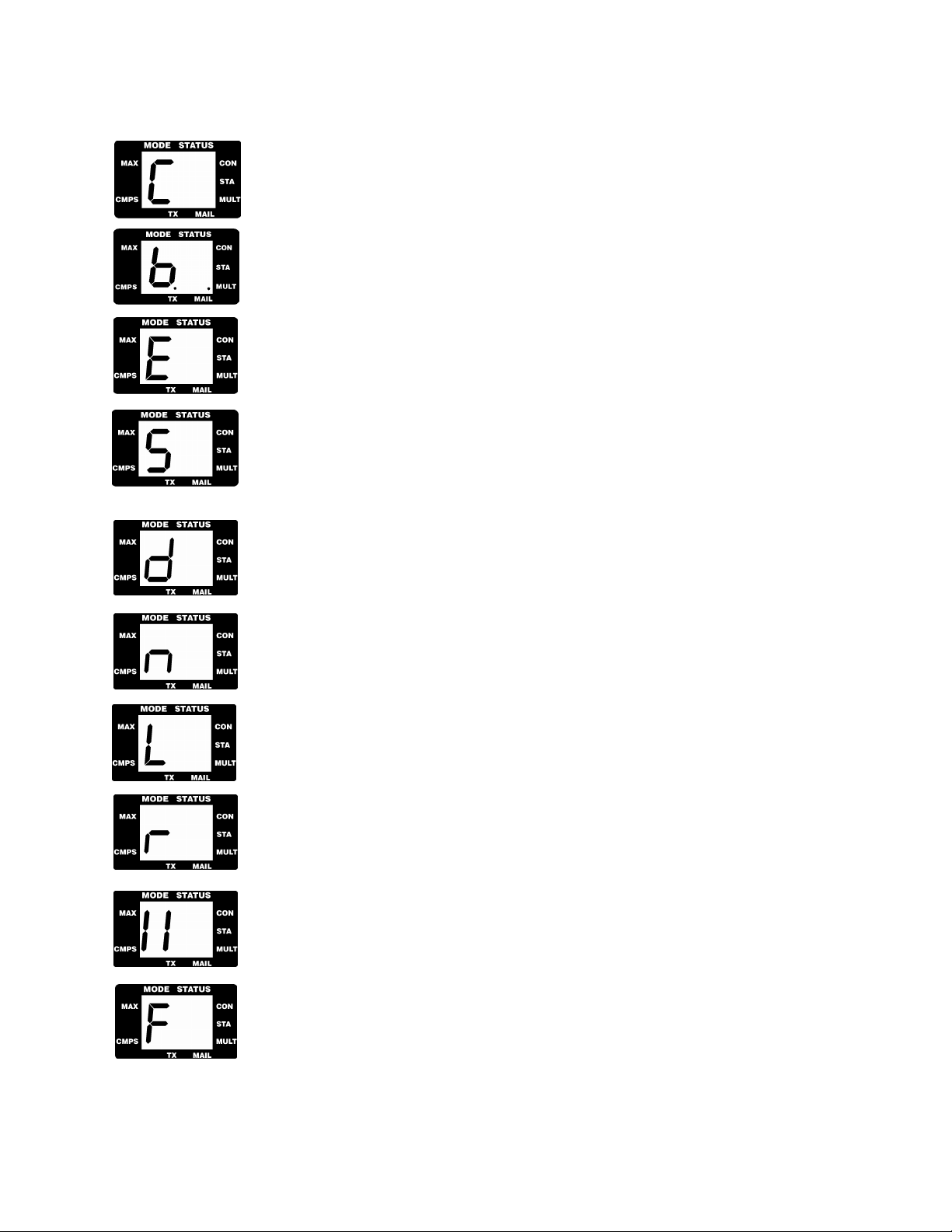
In the Mode area, there are twelve possible symbols that can appear. Below is a rundown of these symbols. You will
find a legend on the front of the DSP-232 which tells you what symbols stand for what mode.
‘P’ will light when you’re using VHF/UHF or HF Packet at 9600, 1200, or 300 bps.
‘A’ will light when you’re in the AMTOR mode.
September, 05 1-3
Page 10
Chapter 1 The DSP-232
‘C’ will light when you’re using the DSP to decode Morse code signals.
‘b’ will light when you’re in the Baudot mode.
‘E’ will light when you’re in the ASCII mode.
‘S’ will light when you’re using Signal Identification and Acquisition mode (SIAM™) to
identify signals.
‘d’ doesn’t stand for an actual mode, but will light during special telemetry and data
conversion applications.
‘n’ will light when you’re copying NAVTEX data.
‘L’ will light when calibrating the DSP.
‘r’ will light when you’re working PACTOR.
‘II’ is an optional symbol which will be used for future applications.
‘F’ is an optional symbol which will be used for future applications.
Status Indicators
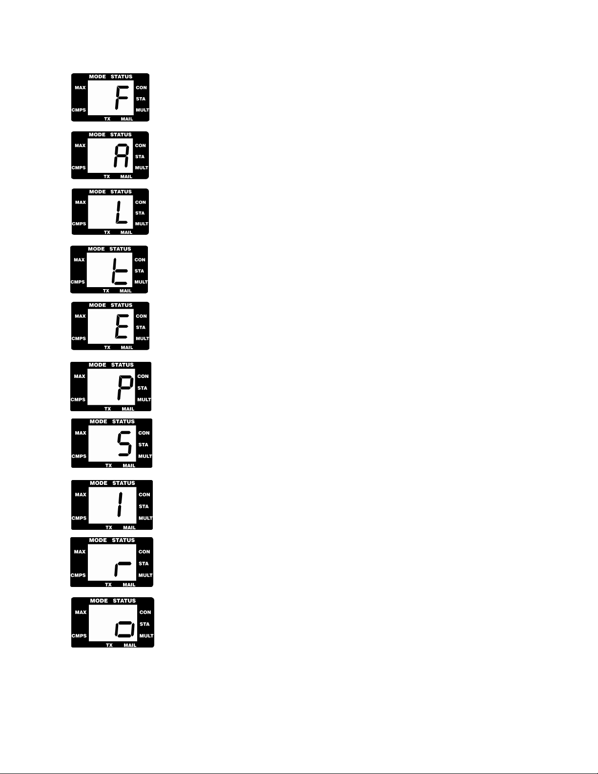
Now, let’s move on to the Status Indicators. There are ten symbols which may appear in the Status area. Below is
an explanation of these symbols. The legend on the front of the DSP-232 tells you what the symbols mean as well.
1-4 September, 05
Page 11
Other Indicators
Chapter 1 The DSP-232
‘F’ lights when you’re in FEC mode in AMTOR or PACTOR.
‘A’ comes on when you’re in ARQ mode in AMTOR.
‘L’ comes on when you’re in Listen mode in AMTOR or PACTOR
‘t’ comes on when sending “traffic” in AMTOR.
‘E’ This stands for ERROR. When not in packet, it’ll glow when it has trouble receiving—
or when it has received—a bad “block” of data while in PACTOR or AMTOR .
‘P’ Stands for PHASE and indicates that while in AMTOR or PACTOR, your transmitter is
trying to lock onto and synchronize with another station’s signal.
‘S’ Stands for SELFEC and will glow when you’re operating SELFEC AMTOR.
‘I’ IDLE is next. When on—while in AMTOR or PACTOR—it indicates that although
you’re connected to another station, no traffic is being transmitted or received.
‘r’ comes on when an error has occurred and the DSP ‘Requests’ a re-transmission.
‘o’ Stands for OVER and lights up when the DSP goes from transmit to receive while in
AMTOR or PACTOR.
September, 05 1-5
Page 12
Chapter 1 The DSP-232
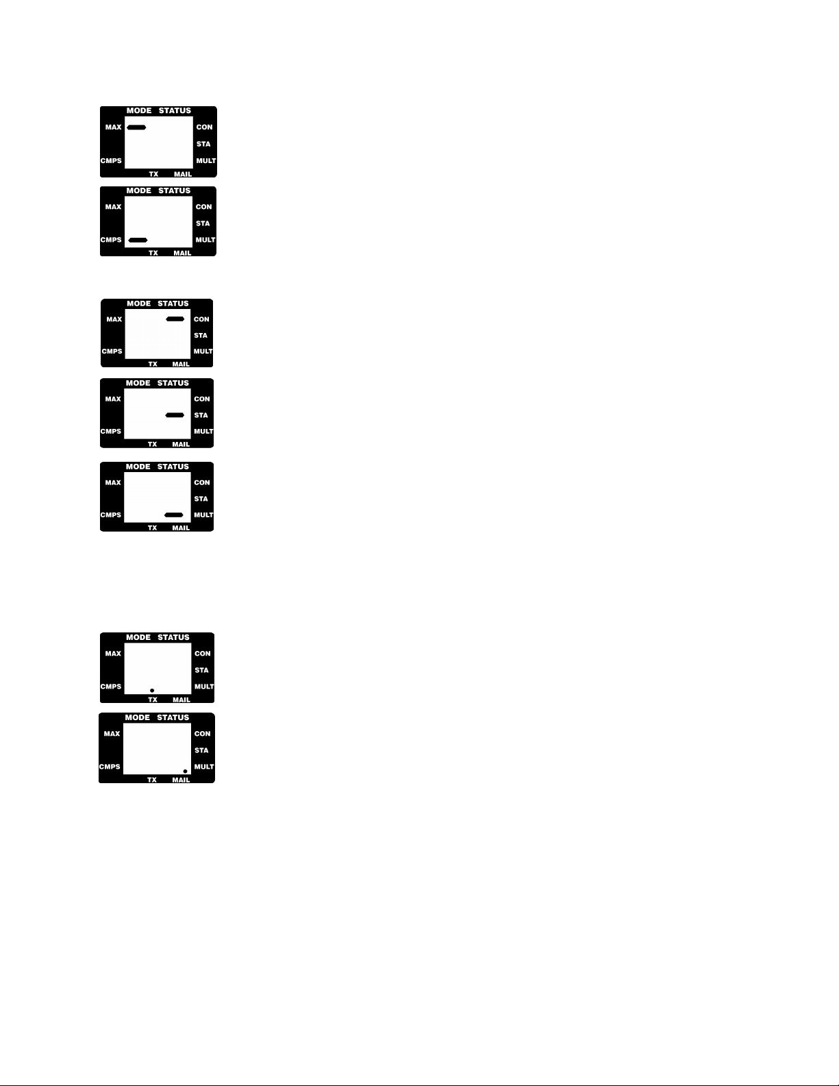
To the left of the Mode LCD display is ‘MAX’. This is the abbreviation for Maximum
Throughput. This will light when PACTOR data is being throughput as fast as the mode
allows. When in PACTOR, with the ‘P’ showing in the Mode area, you will be able to
distinguish the top line of the ‘P’ from this slash because the ‘MAX’ slash will blink.
Also on the left is ‘CMPS.’ This is the abbreviation for Compression. This will light when
data is compressed in PACTOR.
There are three abbreviations to the left of the STATUS portion of the window: CON, STA, and MULT.
CON is the abbreviation for CONnected, and glows while you’re connected to another
station while in packet.
STA is the abbreviation for STAtus, and glows while in packet when you’ve sent a packet
that hasn’t been acknowledged (acked) by another station, yet.
MULT is the abbreviation for MULTiple. It glows constantly while you’re chatting
(connected) with more than one station at a given time while in packet. When the MULT
light blinks, it means that the DSP’s memory (32K standard, expandable to 256K) buffer is
full.
Note: the buffer can be filled with or without the computer connected to the controller since the DSP’s buffer
stores whatever it hears from the radio—not just the computer.
At the bottom of seven-segment LCD displays are two dots labeled: TX and MAIL.
TX stands for Transmit. This LCD dot will glow when you are transmitting data in any
mode.
Mail stands for Mailbox. This LCD dot will blink when you have mail waiting for you in
your mailbox.
Moving to the right is the tuning indicator. When you tune a signal, the LEDs behind the tune window will light a
certain way to tell you whether you’re tuned above or below the frequency of the signal you’re trying to receive.
The ‘Mark’ and ‘Space’ above the TUNE window denotes which way the Mark and Space tones are. With the
LEDs glowing, you’ll refer to the Mark and Space to see if the tones are above or below frequency.
Next is DCD, which means Data Carrier Detect. In HF, whenever your DSP hears anything—be it noise or someone
else’s signal—the LED will glow providing that the threshold is adjusted correctly. If it d oesn’t glow, then it means
that the DSP can’t ‘hear’ any signals. In 1200 and 9600bps VHF packet, the light only glows if a valid packet signal
is heard.
1-6 September, 05
Page 13
Chapter 1 The DSP-232
Just to the right is OVL, which means Overload. When the DSP’s threshold is too high, the Ov erload LED will
glow. Too much volume will allow an excessive amount of noise into the DSP. If this occurs, turn the volume on
the receiver down.
The last LED on the right is the ON indicator. When this LED is glowing, your DSP is being supplied with power.
To the right is the ON/OFF power switch. With it in, the DSP powers up; out, it’s off.
The Back
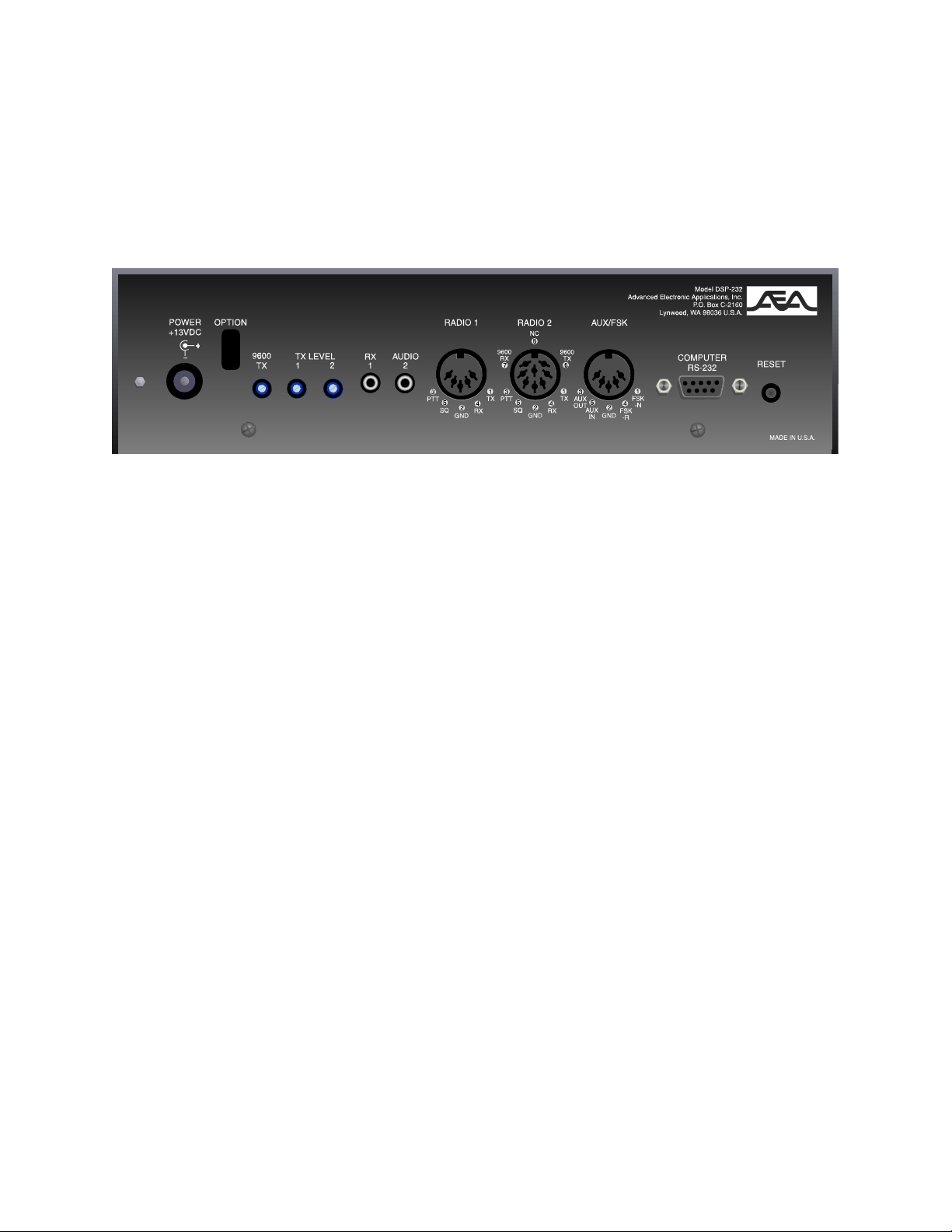
Rear view of the DSP-232
Turn the DSP around so you can see the back. AEA feels that the back of the unit is just as important as the front.
The attention to the back of the unit makes the DSP compatible with the equ ipment you have now, the equipment
you will buy in the future, offers convenient adjusting, and provides upgradability for future applications.
Starting from the left again and moving to the right is the station ground stud. This convenient stud provides a
ground for the equipment in your station.
Next is the 12 VDC POWER receptacle. The center pin is (+) and the ring, or outside, is (−).
Moving to the right are three transmit level adjustments. One for 9600 bps on radio port two, one for radio port one,
and one for radio port two.
RX AUDIO 1 is where the audio output from your receiver or transceiver will go if you don’t (or can’t) use Pin 1 of
the RADIO 1 connector. Use this jack if you have a short-wave receiver or just want to listen with your transceiver.
RX AUDIO 2 has the same function as RX AUDIO 1, but for RADIO 2 port.
The RADIO 1 connector is where you’ll plug in the radio transceiver you plan to designate as Radio 1. (Pins 1 and
5’s locations in that jack are marked under the connector.)
The RADIO 2 connector is where you’ll plug in the radio transceiver you plan to designate as Radio 2. (This is an
eight Pin DIN, equipped to accommodate 9600 bps applications.)
AUX/FSK is used when you want to hook up auxiliary equipment to the controller or want to use FSK (Frequency
Shift Keying) with your HF radio’s accessory port—if it has one.
The RS-232 I/O receptacle is where you’ll plug in the cable that connects to your computer.
Finally, the there is the RESET button which allows you to perform a hard reset on the DSP-232.
This ends your tour of the DSP. Let’s move on to the next chapter to hook up your computer and radio.
September, 05 1-7
Page 14

Chapter 2 Power Supply and Computer Installation
Chapter 2
Power Supply and
Computer Installation
Overview
In this chapter, you’ll power up the DSP and connect it to the RS-232 serial port of your computer. After the
connection has been made, you’ll perform a quick check of the DSP’s internal firmware. You’ll also check the
DSP’s internal modem by performing the all-important “loop-back” test. When you’ve completed this chapter,
you’ll be ready to connect the DSP to your receiver or transceiver and begin using it on the air.
Connecting Power
Before you hook up to your computer, you need to connect power to your DSP. To prevent any potential accidents,
make sure your power supply is off and unplugged before connecting the DSP to a live power source.
(If you have a ready-made power supply, like AEA’s AC-4, insert the coaxial connector into the DSP’s POWER
receptacle, plug the “power cube” into the wall, skip this rest of the section and go to the Turning it On section
below. DO NOT CONNECT YOUR COMPUTER YET.)
Locate the power cable in the accessory bag—the one that’s black but has a white strip running down the length of
one of its conductors—and strip off just enough insulation from the ends of both conductors to connect it to your
12-14 VDC regulated power supply.
! VERY IMPORTANT: your power supply must provide at least 12 VDC @ 1A under load to the DSP for it to
operate correctly.
Fasten the positive (+) lead—the one which has the white stripe running down its length—to the (+) terminal of
your power supply. Connect the other conductor to the negative (−) terminal of your power supply. Insert the
coaxial power plug into the POWER receptacle on the left rear of the DSP. DO NOT CONNECT YOUR
COMPUTER YET.
Turning it On
With the power connections made, turn on your power supply (or plug in the power cube into the wall outlet) then
depress the POWER switch on the front of the DSP. WATCH CLOSELY FOR THE FOLLOWING: the power
LED to glow, the ‘AU’ (AU stands for Autobaud) to light in the 7-segment Mode and Status windows, and the tune
bar LEDs to become active. If this occurs, then switch off the DSP and move on to the section, Connecting Your
Computer to the DSP. If the above doesn’t happen, then go to Chapter 13 - Troubleshooting.
Note: If something other than ‘AU’ glows, the controller probably has been previously initialized and
should be reinitialized as described below.
Re-Initialization
September, 05 2-1
Page 15

Chapter 2 Power Supply and Computer Installation
If the DSP has been previously initialized, it’s ready to communicate with a computer or terminal at a specific baud
rate (probably 300, 1200, 2400, 4800, 9600 or 19,200bits/sec) or was shut off in the last mode it was operating in,
like packet or Morse. Reinitializing the controller will make it “forget” all of its user-defined parameters and
will return it to its factory default settings. However, by reinitializing it now you’ll have an easier time getting it
up and running later.
To re-initialize the DSP:
1. Turn power off (power button out.)
2. Press and hold the RESET button on the back panel of the DSP.
3. Continue holding the RESET button and turn the DSP on (power button in.)
4. Continue holding the reset button in for five seconds to insure that the controller’s memory has forgotten
all of its previously set parameters.
5. Release the reset button and the unit has been re-initialized.
If the above procedure didn’t restore the proper start-up operation of the DSP’s front panel LEDs, then refer to
Chapter 13 - Troubleshooting.
Connecting Your Computer to the DSP
Make sure that the DSP and computer are turned off before proceeding.
The Cable
For communication to take place between your computer and the DSP, you need a properly wired, shielded cable
that’ll connect the computer’s serial port to the RS-232 I/O port on the back of the DSP. (The cable that
accompanies your DSP is pinned correctly and is ready to use.)
The style of connector you have on your computer is probably a DB-25F (25-pin), a DB-9 (9-pin), or a mini Din-8
for Apple computers (8-pin).
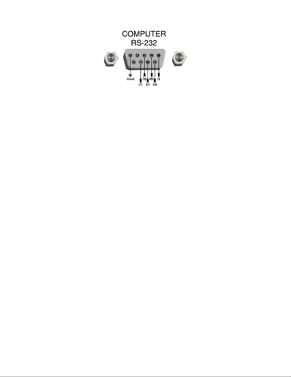
Here’s a table of pin assignments to wire the DSP’s RS-232 I/O port to a typical computer’s serial port see diagram
on next page:
from Apple
DSP-232 to... miniRS-232 I/O DB-25F DB-9 DIN-8P Function
1 8 1 2 (DCD)
2 3 2 5 (RxD)
3 2 3 3 (TxD)
5 7 5 4+8 (GROUND)
6 6 6 (DSR)
7 4 7 (RTS)
8 5 8 (CTS)
2-2 September, 05
Page 16
Chapter 2 Power Supply and Computer Installation
Don’t use a “null modem” cable. This type of cable flips pins 2 & 3 so that pin 2 on one end of the cable is
connected to pin 3 on the other end (and vice versa.) Use a cable that has “straight through” connections like the
ones used to connect computers to a telephone modem since as far as your computer’s concerned, the DSP is a
modem.
Once you’ve tested the cable to make sure it’s pinned correctly, plug one end into your computer’s serial port and
the other end to the RS-232 I/O port on the back of the DSP, then proceed to the System Start-up and Loopback Test
later in this chapter.
Note: The enclosed computer cable was designed to connect directly to a 9-pin, IBM-PC/XT/AT
compatible computer’s RS-232 port. Some less-common machines are listed below.
Apple Computers
If you own an Apple Macintosh or Powerbook-type computer, simply purchase a standard mini-DIN8 to DB-9
modem cable.
Dumb Terminals
If you have an RS-232 “dumb” computer terminal, you may need to change the gender of the cable provided with
your DSP. This can be done with an inexpensive double-male RS-232 gender changing adapter available from
Radio Shack (part number 26-1388, Radio Shack Port Adapter) as well as other computer dealers.
The Computer
If the type of computer you plan to use with the DSP wasn’t mentioned earlier in this chapter, you may find
specific connection information below. You’ll also need a communications program to use with your computer. See
The Control Program section below for information regarding communication programs for many of the above
machines.
Many computers require a serial port adapter card that incorporates the necessary RS-232-C interface circuitry; The
IBM-PC is a good example of this. Computers that don’t have a serial port or permit use of a suitable adapter or
level converter can’t be used with the DSP.
Other Computers with RS-232 Ports
If your computer has an RS-232 port, consult your computer manuals to see which pins are used for TxD, RxD and
signal ground. Read the manufacturer’s recommendations for connecting the serial port to a telephone-type modem
and connect your DSP the same way.
The DSP-232 is configured as Data Communications Equipment (DCE)—it transmits data on pin-2. Most
computers and terminals are configured as Data Terminal Equipment (DTE) transmitting data on pin-3.
If your computer is configured as Data Terminal Equipment (DTE), use the supplied RS-232 cable with a gender
changing adapter, if necessary. These are available from Radio Shack (part number 26-1388) and other computer
stores.
September, 05 2-3
Page 17

Chapter 2 Power Supply and Computer Installation
Other Computers with Non-Standard Serial Ports
Computers with non-standard serial ports must meet the following conditions:
♦ The signal levels must be compatible with RS-232-C. The DSP requires the voltage levels from the computer
be greater than +3 volts in the “asserted” state and 0 volts or less in the “non-asserted” state.
♦ The signal polarity must conform to the RS-232-C standard. The 0 or negative-voltage state must correspond
to logical “1” and the positive-voltage state to logical “0 .”
♦ The computer must be able to correctly receive a signal that meets asynchronous RS-232-C specifications.
The DSP supplies signals that meet this specification.
Make or buy a cable that provides the following connections:
♦ The computer’s serial port signal ground or common pin must be connected to the DSP’s serial port
connector, pin 5.
♦ The pin on which the computer SENDS data (TxD) must be connected to the DSP’s RS-232 connector, pin 3.
♦ The pin on which the computer RECEIVES data (RxD) must be connected to the DSP’s RS-232 connector,
pin 2.
If your computer requires any other signals, you must arrange to provide them. The DSP has the standard hardware
handshake lines available. As a default, the DSP provides XON/XOFF software flow control to the computer or
terminal. The command, XFLOW, can be turned off, disabling software flow control and enabling hardware
handshake if your computer requires it. Hardware flow control is achieved with RTS/CTS (pins 7 and 8) of the DB9 RS-232 I/O connector. The documentation provided with your computer or serial card should clarify any special
requirements.
Peripherals and IRQ Conflicts in IBM-PC Compatibles
On a different note, you need to survey your computer system to see what peripherals are connected to it, both
internally and externally. This is important since you can’t connect the DSP to a COM port that’s shared or
occupied by another device like a modem, fax, or mouse card. For example, you may not be able to connect your
DSP to COM 1 if COM 3 is occupied by another device; the same holds true with COM 2 and COM 4. COM ports
are usually paired, meaning COM 1 “sees” what’s connected to COM 3, and COM 2 sees what’s connected to COM
4.
The reason why you have to be careful with COM port pairs is due to something called an Interrupt ReQuest (IRQ)
conflict—devices and peripherals send a distinct set of signals back to the CPU to interrupt its operation when the
device needs “attention.” When two devices have the same IRQ codes, their signals fight for the CPU’s attention
and cause all kinds of trouble. Therefore, if COM 1 or COM 3 are occupied, connect the DSP-232 to COM 2 or
COM 4 if you can. If you can’t, you’ll have to change the hardware (and software) to another IRQ so the shared
devices can “live together” on the paired port. Changing the device’s IRQ from 3 to 5 usually works. (Refer to the
device’s manual for changing its IRQ setting.)
Along the same lines as conflicts, sometimes a TSR (Terminate and Stay Resident) program can cause a
communication problem between the DSP and your computer. Therefore, when setting up your controller for the
first time, disable all of your TSRs to eliminate any potential start-up problems. An easy way to do this is to create a
system disk on “floppy” (in DOS, type
FORMAT A: /S to create a system disk), start-up your computer from that,
then access the communications program you plan to use with your controller.
To prevent programs from automatically booting in your Macintosh or Powerbook, simply hold down the (SHIFT)
key on power-up until you see the Welcome to Macintosh , Extensions Off message.
The Control Program
If you are going to use the PC PakRatt for Windows program supplied with your DSP-232, you will follow the
instructions in the PC PakRatt for Windows manual to install the software on your computer. If you’ll be using your
DSP with a dumb terminal, you won’t need any software and can skip to the next section, System Start-up and
Loop-back Test.
2-4 September, 05
Page 18

Chapter 2 Power Supply and Computer Installation
The DSP operates in much the same manner as a telephone modem so most telephone modem terminal programs
will work with your DSP. Some of these programs are in “Public Domain” which means they’re free. Other terminal
programs are “shareware” which means you may get them from a friend and try them before you buy them.
Follow the installation directions that come with the terminal program you plan to use. On ce installed on your
computer, you should start the program and set its parameters to:
♦ Data Rate = 1200 bits per second (Baud)
♦ Data bits/word length = 7
♦ Parity = EVEN
♦ Stop bits = 1
♦ Duplex = FULL
♦ Handshake = XON/OFF
Note: Early version of PC PakRatt for Windows 2.0 do not list the DSP-232 in the TNC menu. To operate
your DSP-232, you will select the DSP-1232 from the TNC menu. To PC PakRatt for Windows, your
DSP-232 ‘looks’ just like a DSP-1232. Later versions of PC PakRatt for Windows have the DSP-232 listed
in the TNC menu. THIS IS THE ONLY DIFFERENCE BETWEEN EARLY AND LATE RELEASES
OF PC PAKRATT FOR WINDOWS version 2.0.
Note: as a default, the DSP provides XON/XOFF software flow-control to the computer or terminal. The
DSP command, XFLOW, can be turned OFF to disable software flow control and enable hardware
handshake if your computer requires it. Hardware flow control is achieved with RTS/CTS (pins 7 and 8)
of the DB-9 RS-232 I/O connector.
IBM PCs and Compatibles
Although you can use almost any terminal program with your IBM-PC or compatible computer, AEA currently sells
PC-Pakratt-II for DOS and PC-Pakratt for Windows; programs which provide many features not available in
telephone modem programs. (Call AEA’s 24-hour Literature Request line at 800-432-8873 and leave a message.)
Of course, you already own PC PakRatt for Windows.
If you already have one of AEA’s PakRatt programs, follow the instructions in the program’s manual to install the
software on your computer. For initial checkout of the DSP, use the programs’ Dumb Terminal mode.
A partial list of PC programs tested with the DSP includes: PROCOMM Plus, LANLINK, PC PakRatt for Windows
2.0 and 1.0, PC PakRatt II for DOS, YAPP, and the terminal program included with Microsoft Windows 3.1.
Apple Macintosh and Powerbooks
Although you can use almost any Macintosh-based terminal program with your Macintosh or Powerbook, AEA
presently sells the MacRATT program which provides many features not available in telephone modem-type
programs. Again, call or write AEA for more information.
If you already have MacRATT, follow the program’s manual to install the software on your computer. For initial
checkout of the DSP, use MacRATT’s Dumb Terminal mode.
As we mentioned above, an AEA program is not required to use the DSP with your Macintosh or Powerbook. A
partial list of Macintosh programs tested with the DSP includes: MAC TERMINAL, RED RYDER,
MICROPHONE II, SMARTCOMM II and MOCK TERMINAL.
System Start-up and Loop-back Tests
Make sure that you’ve connected your DSP to an adequate power supply and to the RS-232 port of your computer
or terminal.
Radio Port 1 Test
September, 05 2-5
Page 19

Chapter 2 Power Supply and Computer Installation
1. Don’t connect any cables to your radio yet!
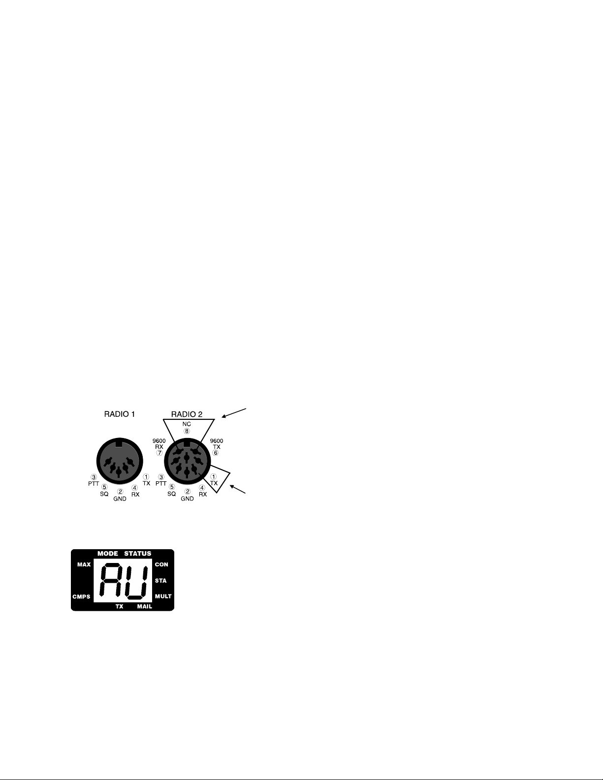
2. If a loop-back jumper is included with your shipment of the DSP-232, plug one end into the 1 hole (TX)
and the other end into the 4 hole (RX) of Radio 1 port on the back of the DSP-232, and go to step 7. If you
did not receive a loop-back jumper, continue following the steps.
Insert Loop-back jumper in holes 1 and 4
3. Remove one of the 5-wire, shielded radio cables from the DSP accessory bag. If you have a single 10-Ft.
cable with 5-pin connectors on each end, cut the cable to the length you need to reach your primary radio.
4. With your pocket knife or wire strippers, remove about an inch (2.5 cm) of cable jacket exposing the five
colored wires and the shield-wire, being careful not to accidentally nick the wires’ insulation.
5. Strip about 1/4 inch (7 mm) of insulation from the green and white wires and short them together by
twisting gently twisting their ends together.
6. Plug the cable into the 5-pin RADIO-1 socket on the DSP’s rear panel. Make sure that the cable at the
connector end faces downward as it leads away from the controller.
7. Set the RADIO 1 AFSK LEVEL pot on the rear of the DSP to 50% rotation (straight up and down) using a
small screwdriver.
8. Turn on your computer. Load and run your communications program. (Choose the TTY option, if
available.)
If you’re using an AEA program, follow its manual’s instructions to enter the packet mode, then skip to Step 11.
Note: Early version of PC PakRatt for Windows 2.0 do not list the DSP-232 in the TNC menu. To operate
your DSP-232, you will select the DSP-1232 from the TNC menu. To PC PakRatt for Windows, your
DSP-232 ‘looks’ just like a DSP-1232. Later versions of PC PakRatt for Windows have the DSP-232 listed
in the TNC menu. THIS IS THE ONLY DIFFERENCE BETWEEN EARLY AND LATE RELEASES
OF PC PAKRATT FOR WINDOWS version 2.0.
Note: You may use a wide range of terminal baud rates with the DSP, but we recommend 1200 baud now
to keep this procedure easy and consistent.
9. Press the DSP’s power switch to the ON position.
The seven segment LCD symbols ‘AU’ (AU stands for Auto Buad) will light. (If the
above doesn’t happen, then refer to Chapter 13 - Troubleshooting.
If your serial port is operating at 1200 baud (this is the terminal baud rate), 7-bit even parity as recommended, you’ll
see the following message:
Please type a star (*) for autobaud routine.
If your serial port is operating at 2400, 4800, 9600, or 19,200 baud (this is terminal baud), you may see some
“garbage” characters. This is normal and you should proceed with Step 10.
2-6 September, 05
Page 20

Chapter 2 Power Supply and Computer Installation
10. Type an asterisk (*). When the DSP has recognized your computer’s data rate, its ‘AU’ lights will glow as
in the picture above. Your screen will then display the following sign-on message:
AEA DSP-232 Data Controller
Copyright (C) 1995 by
Advanced Electronic Applications, Inc.
Release DD.MMM.YY
cmd:
”cmd:” is the DSP’s system prompt. When you enter (or have entered) a command, you’ll see this prompt.
Important: When you enter a parameter or command, type it after the prompt, press the (SPACE) bar once, enter
the command’s “argument” (the variable or text you’re changing) if appropriate, then press (RETURN).
At this point the DSP-232 is in its default mode: 1200 bps VHF Packet.
11. Set the DSP to RADIO PORT 1by typing RADIO 1 (or RAD 1) at the cmd:like this:
RAD 1
11. Enter the following text after the cmd: prompt to set your test callsign to AAA:
MYCALL AAA
After you’ve entered this, the DSP will print the following on the screen:
MYcall was DSP232
MYcall now AAA
12. Enter the following command to “connect” to AAA: (the DSP-232 recognizes the letter C to mean “connect
to...”)
C AAA
After a few moments, your monitor should display:
*** CONNECTED to AAA
13. Type Hi, there!, then press (RETURN). Your monitor should echo the same message.
If you’ve gotten this far, then the DSP and its VHF packet modem is working properly. If you’re having difficulties,
see Chapter 13 - Troubleshooting.
14. You’ll now check the DSP’s HF modem. Enter a (CTRL-C) so you’ll return to the Command mode. After
the cmd: prompt, enter:
DISCONNECT
The command HBAUD (or HB for short) controls the data rate of the DSP-232. Currently, the DSP-232 is in 1200
bps (HBAUD 1200) VHF Packet. You want to be in 300 bps HF Packet. After the cmd: prompt, enter:
HB 300
Your monitor should respond with:
HBAUD was 1200
HBAUD now 300
cmd:
15. Enter the following command to “connect” to AAA:
C AAA
16. Type Hi, there!, then press ENTER or RETURN. Your monitor should echo the same message.
September, 05 2-7
Page 21
Chapter 2 Power Supply and Computer Installation
17. Now you’ll exit out of the packet mode. The following command will force the DSP to “disconnect” from
a station and exit the packet mode:
(CTRL-C)
cmd:D
The DSP-232 recognizes the letter D to mean “disconnect from...”
Your monitor should respond with:
cmd:***DISCONNECTED: AAA
AAA*>AAA (UA)
If all of the above steps were successful, you’ve completed the system check-out for Radio Port 1. Press (CTRL C) and the cmd: prompt will display on your screen. At the cmd:, type RESET.
If you experienced problems with the above procedure, go back to Step 1 after checking all the cables and
connectors for proper wiring, continuity, and connection. Read each step again carefully. The most common errors
made during this procedure are: trying to connect to a callsign different from AAA; not having the green-and-white
wires connected; or not setting the AFSK level to 50% rotation.
Radio Port 2 Test
Now you need to perform the Loop-back test for Radio Port 2. You will do the VHF and HF Packet tests just as you
did before, plus you will test the 9600 bps VHF Packet modem on Radio Port 2.
1. Take the Loop-back jumper that came with your DSP-232, or the jumper you crafted for the previous test
an plug one end into 1 hole (TX) and the other end into the 4 hole (RX) of the 8-pin RADIO-2 socket on
the DSP’s rear panel. This is the 1200 bps VHF & 300 HF Loop-back jumper placement shown below.
You will use the 9600 bps placement later in this section.
9600 bps Loop-back jumper placement.
1200 bps VHF & 300 HF Loop-back jumper placement.
2. Set the RADIO 2 AFSK LEVEL pot on the rear of the DSP to 50% rotation (straight up and down) using a
small screwdriver.
The seven segment LCD symbols ‘AU’ will light. If the above doesn’t happen,
then refer to Chapter 13 - Troubleshooting.
If your serial port is operating at 1200 baud (this is the terminal baud rate), 7-bit even parity as recommended, you’ll
see the following message:
Please type a star (*) for autobaud routine.
If your serial port is operating at 2400, 4800, 9600, or 19,200 baud (this is terminal baud), you may see some
“garbage” characters. This is normal and you should proceed with Step 10.
2-8 September, 05
Page 22

Chapter 2 Power Supply and Computer Installation
3. Type an asterisk (*). When the DSP has recognized your computer’s data rate, its ‘AU’ lights will glow as
in the picture above. Your screen will then display the following sign-on message:
AEA DSP-232 Data Controller
Copyright (C) 1995 by
Advanced Electronic Applications, Inc.
Release DD.MMM.YY
cmd:
At this point the DSP-232 is in its default mode: Radio Port 1, 1200 bps VHF Packet.
4. Enter the following text after the cmd: prompt to switch to Radio Port 2
RAD 2
5. Enter the following text after the cmd: prompt to set your test callsign to AAA:
MYCALL AAA
After you’ve entered this, the DSP will print the following on the screen:
MYcall was DSP232
MYcall now AAA
6. Enter the following command to “connect” to AAA: (the DSP-232 recognizes the letter C to mean “connect
to...”)
C AAA
After a few moments, your monitor should display:
*** CONNECTED to AAA
7. Type Hi, there!, then press (RETURN). Your monitor should echo the same message.
If you’ve gotten this far, then the DSP and its Radio Port 2 VHF packet modem is working properly. If you’re
having difficulties, see Chapter 13 - Troubleshooting.
8. You’ll now check the DSP’s Radio 2 HF modem. Enter a (CTRL-C) so you’ll return to the Command
mode. After the cmd: prompt, enter:
DISCONNECT
After the cmd: prompt, enter:
HB 300
Your monitor should respond with:
HBAUD was 1200
HBAUD now 300
cmd:
9. Enter the following command to “connect” to AAA:
C AAA
10. Type Hi, there!, then press
11. Now you’ll exit out of the packet mode. The following command will force the DSP to “disconnect” from
a station and exit the packet mode:
(CTRL-C)
cmd:D
ENTER or RETURN. Your monitor should echo the same message.
September, 05 2-9
Page 23

Chapter 2 Power Supply and Computer Installation
The DSP-232 recognizes the letter D to mean “disconnect from...”
Your monitor should respond with:
cmd:***DISCONNECTED: AAA
AAA*>AAA (UA)
Now you need to to the Loop-back test for 9600 bps on Radio Port 2. You need to take your wire Loop-back jumper
and plug one end into the 7 hole (9600 RX) and the other end into the 6 hole (9600 TX) of Radio Port 2. For those
using the cable method (described previously), unplug the cable and take a paper clip, straighten it out, bend it in
half, and insert it into RADIO PORT 2 as described above.
12. Set the 9600 TX AFSK LEVEL pot on the rear of the DSP to 50% rotation (straight up and down) using a
small screwdriver.
13. Press (CTRL - C). When the cmd: displays on your monitor, type: RESET.
The seven segment LCD symbols ‘AU’ will light. (If the above doesn’t happen,
then refer to Chapter 13 - Troubleshooting.
If your serial port is operating at 1200 baud (this is the terminal baud rate), 7-bit even parity as recommended, you’ll
see the following message:
Please type a star (*) for autobaud routine.
If your serial port is operating at 2400, 4800, 9600, or 19,200 baud (this is terminal baud), you may see some
“garbage” characters. This is normal and you should proceed with Step 10.
14. Type an asterisk (*). When the DSP has recognized your computer’s data rate, its ‘AU’ lights will glow as
in the picture above. Your screen will then display the following sign-on message:
AEA DSP-232 Data Controller
Copyright (C) 1995 by
Advanced Electronic Applications, Inc.
Release DD.MMM.YY
cmd:
At this point the DSP-232 is in its default mode: Radio Port 1, 1200 bps VHF Packet.
15. Enter the following text after the cmd: prompt to switch to Radio Port 2
RAD 2
16. At the command prmopt type:
MODEM 16
This is an alternate means of selecting a modem. We use HBAUD in previous examples, and you could at
this point too. But, in an effort to get you familiar with the DSP-232’s commands, we had you use the
MODEM command. (After you are done with this entire Loop-back test type DIRECT at the cmd: to see
the whole list of modems available for the DSP-232.)
17. Now to make the Loop-back test work, at the cmd:, type:
HBAUD 9600
2-10 September, 05
Page 24

Chapter 2 Power Supply and Computer Installation
18. Now, at the cmd:, type:
EXPERT ON
Press (RETURN) and then type:
UBIT 0 OFF
19. Enter the following text after the cmd: prompt to set your test callsign to AAA:
MYCALL AAA
After you’ve entered this, the DSP will print the following on the screen:
MYcall was DSP232
MYcall now AAA
20. Enter the following command to “connect” to AAA: (the DSP-232 recognizes the letter C to mean “connect
to...”)
C AAA
After a few moments, your monitor should display:
*** CONNECTED to AAA
21. Type Hi, there!, then press (RETURN). Your monitor should echo the same message.
22. Now you’ll exit out of the packet mode. The following command will force the DSP to “disconnect” from
a station and exit the packet mode:
(CTRL-C)
cmd:D
If you’ve gotten this far, then the DSP and its Radio Port 2 9600 bps VHF packet modem is working properly.
If you still have problems after consulting Chapter 13 - Troubleshooting, leave your DSP on and call AEA’s
Technical Support department at (206) 775-7373. If all tests went well, your DSP’s modems and Radio Ports are
functioning properly. Any problems that arise from this point on will most likely stem from cabling or radio
problems. Now, move on to Chapter 3 Radio Installation.
September, 05 2-11
Page 25
Chapter 3 Radio Installation
Chapter 3
Radio Installation
Overview
This chapter describes how to connect the DSP-232 to your radio receiver or transceiver.
If You Just Want to Listen
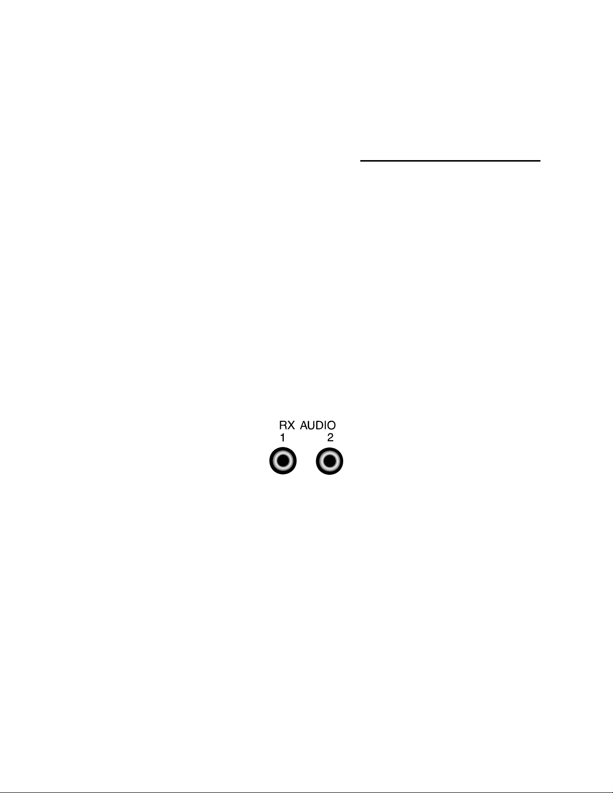
If you’re a short-wave listener or are only interested in receiving and not transmitting signals, the audio connection
to the DSP is simple—just plug one end of the supplied audio cables into either the RX AUDIO 1 or AUDIO 2
jacks on the rear of the DSP (as shown in Figure 3-1 below) and the other end of the cable is into the external
speaker/earphone jack of your radio.
Note: some short-wave receivers come with low-level outputs designed for use with a tape recorder. These
outputs typically don’t have enough power to drive the DSP circuitry—the DSP needs at least 200 mV
for it to operate correctly.
Figure 3-1 Receive audio connections to the DSP.
If You Want to Transmit. . .
. . . you’ll need to make the proper connections to your radio’s speaker, microphone and the Push-To-Talk (PTT)
circuits.
The best way to connect the DSP to your transceiver is through its rear panel accessory port, if it has one—it’ll free
up the mike jack so you don’t have to swap connectors with your mike and the DSP when you want to use either
device. If your radio doesn’t have an accessory port, use its microphone connector for hook-up.
p-p
Note: if your controller is connected to your radio’s Accessory port and you leave your mike plugged in, if
you accidentally key the mike it’ll cause your radio to transmit whatever it hears from the DSP.
Radio Connection Requirements
! Very Important: MAKE SURE THAT YOU REMOVE POWER FROM YOUR DSP AND RADIO
BEFORE MAKING ANY OF THE FOLLOWING CONNECTIONS.
You’ll need the following items to make a radio cable to connect the DSP to you r transceiver:
September, 05 3-1
Page 26

Chapter 3 Radio Installation
• the AEA-supplied radio cable for each radio you want to connect
• a microphone or accessory-plug connector for your transceiver
• a pin assignment diagram of your radio’s microphone and/or accessory port
• a low-wattage (under 40W) soldering iron and solder
• wire cutters, strippers or a small pocket knife
The lines you’ll be connecting from your radio to the DSP are:
♦ Receive Audio: carries the audio signals from your radio’s internal or external speaker or headphone jack
to the DSP. The audio can usually be tapped from a particular pin in your transceiver’s mike connector or
through your radio’s external speaker jack.
♦ Microphone Audio (AFSK): carries the transmit audio signal from the DSP to your transceiver for
transmission.
♦ Ground: provides an electrical return-path for the DSP’s DC signals.
♦ PTT: when energized—like when you press the button on your mike—it puts your transceiver into
transmit.
If your transceiver has these four lines, then you shouldn’t have any problem getting your radio to work with the
DSP.
Connections for Specific Transceiver Models
Appendix A contains information and diagrams for connecting the DSP to many modern HF and VHF transceivers.
Go there to locate the transceiver model(s) you’ll be connecting to your DSP and at the same time, refer to your
radio’s Operating or Owner’s manual to verify that the pin assignments are correct. (If you don’t find your
transceiver listed there, then locate a model from the same manufacturer that has the same accessory or mike
connector and pinouts as the unit you’ll be connecting—usually each manufacturer has consistent pin assignments
so the hook-ups will be the same.)
! Very Important: IF YOU HAVE ANY QUESTIONS OR DOUBT ABOUT YOUR MANUAL’S WIRING
DIAGRAM FOR YOUR RADIO OR THERE’S A DIFFERENCE IN THE PIN-OUT DIAGRAMS
BETWEEN YOUR RADIO’S MANUAL AND OURS, CALL OR WRITE YOUR RADIO’S
MANUFACTURER OR AEA FOR ASSISTANCE.
Basic Connections and Adjustments
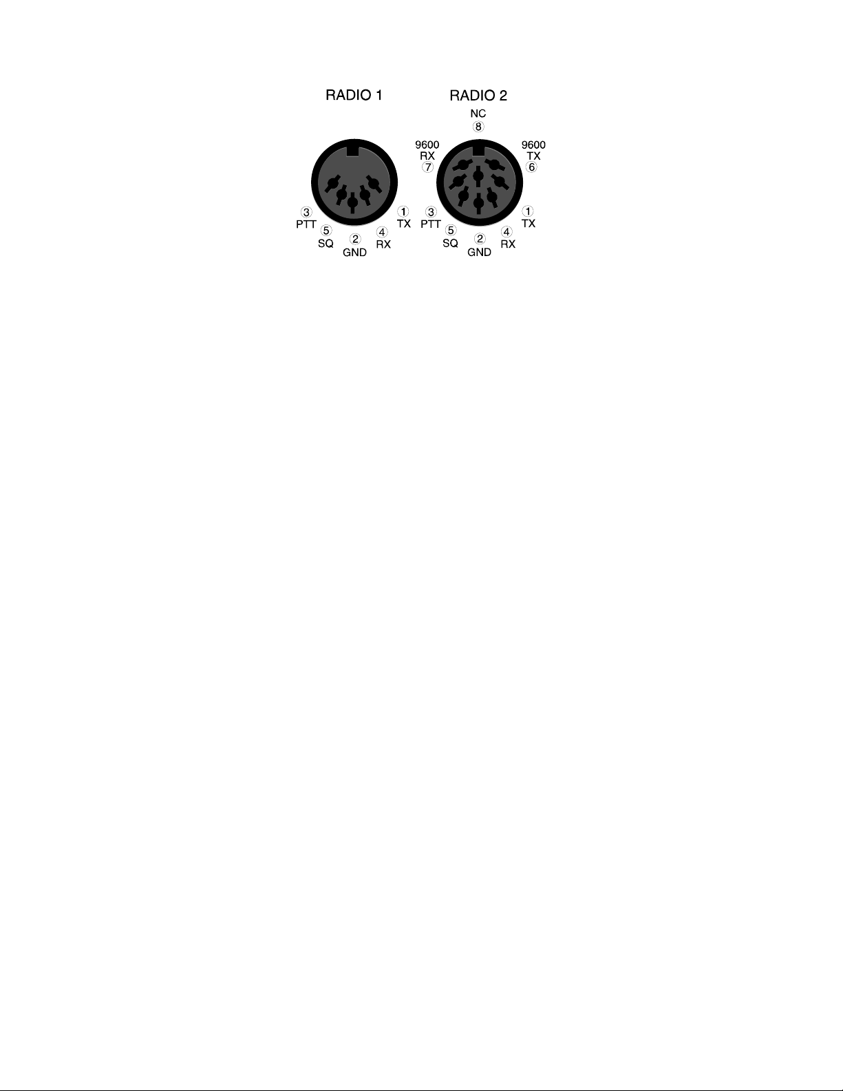
The following table (3-1) and figure (3-2) will help you identify the connection points to the DSP’s radio cable.
Wire
Pin Signal Name Color Description
4 Receive Audio Green Audio from your radio to the DSP
1 Microphone Audio White Transmit audio from the DSP to your transmitter
5 Squelch Input Black Squelch input from radio (optional)
2 Ground Brown Audio and PTT common return
3 Push-To-Talk Red Keying line to your transmitter
Shield/Drain Wire Silver Shield of cable / Microphone ground
Radio Port 2 has these 9600bps packet connections also
6 Receive Audio Green Audio from your radio to the DSP
7 Microphone Audio White Transmit audio from the DSP to your transmitter
Table 3-1 Radio Port 1 and 2 and Cable Connections
3-2 September, 05
Page 27
Chapter 3 Radio Installation
Figure 3-2 DSP to Radio Cable Connections for Radio Ports 1 and 2
If you’ll be using a Packet channel that’s shared with voice users, then you should connect the black wire to the
Squelch status pin of the connector. This will prevent the DSP from transmitting when there’s a received signal
strong enough to open the squelch. If you connect this pin, you may have to change the setting of the SQUELCH
command in the DSP. (Most VHF/UHF Packet operations are no longer shared with voice users so this connection
generally isn’t needed.)
As an example for determining the Radio cable connection to a radio, let’s say you want to hook up an Alinco DR112 to your DSP. Go to Appendix A and turn to the page listing the Alinco radios. There, the DR-112 is listed and to
its right—under the Figure column—it refers you to Figure 2 and the Notes column, Note 1. Turn to the first page
of the Appendix and read Note 1. It doesn’t really apply because if we look at Fig. 2 on the next page, it shows that
the green wire in the Radio cable, Receive Audio, is hooked up to pin 6 in the Alinco’s mike connector. The brown
wire, Ground, is connected to pin 7; the braided cable shield, to pin 8; the white wire, Mike Audio (AFSK) to pin 1,
and finally the red wire, PTT, to pin 2.
So, to fashion the radio cable:
1. Locate one of the 5 ft. DSP radio cables included with your DSP.
Note: that the Radio cables may have been shipped as a single 10 ft. cable which should be cut to
length before use.
2. Prepare the bare end of one of the radio cables by removing an appropriate amount of jacket for the mike
connector you’ll attach. Typically, this is .5 - .75 inches (13 - 19mm).
3. Carefully remove the foil shield exposing the colored wires underneath. Be careful not to nick or cut the
shield wire.
4. Strip back about .125 inch (7mm) of colored insulation from the green, red, white and brown wires. (Don’t
strip back the black wire if you don’t intend to use it—just cut it short)
5. Feed the connector’s backshell over the cable end, then look at the connector closely (with a magnifying
glass, if necessary) to locate pin 1. Compare this to the location of pin 1 on the connector drawing in your
transceiver’s manual and also in Appendix A. This is important as some diagrams show the connector from
the inside of the transceiver, not the outside of the plu g you are wiring. (This will help insure that the plug
is not wired backwards.)
6. Warm up your soldering iron and begin wiring.
Note: when wiring a connector, it’s often easier to wire the inside or middle pins first then work
your way to the outside pins.
7. Connect the Shield (silver) wire to the mike’s ground connection if your transceiver has one. If it doesn’t
have a separate mike or ground connection, then connect it to the single ground along with the Brown wire.
(See the next step.)
September, 05 3-3
Page 28

Chapter 3 Radio Installation
8. Connect the brown wire to the main ground on the connector. This ground is the one used for the PTT and
receive audio. You should connect the Silver Shield/Drain wire to this ground only if there isn’t a separate
mike ground as described in the previous step.
For PTT, the DSP keys only positive (+)PTT since most transceivers use this method of keying. If you’re
connecting a handheld (“handy-talkie”) transceiver to your DSP, you’ll probably need a resistor and/or capacitor to
isolate this connection from the AFSK audio. (Check Appendix A).
Connect the green wire to the Receive Audio terminal on the connector. If the connector you’re wiring doesn’t have
Receiver Audio available, then the included 3.5 mm audio cable may be used instead. This cable connects audio
from your transceiver’s external speaker/earphone jack to the RX AUDIO jack on the DSP. If you’re connecting to
an Accessory jack, make sure the available level is at least 200 mV
Connections for Direct-FSK on RTTY
Some HF SSB radios provide direct FSK (Frequency-Shift Keying) for RTTY, AMTOR and PACTOR operation.
RMS
.
Note: when using narrow filters they can limit the data transfer rate at 110 baud. Consult your
transceiver’s manual regarding direct FSK operation for further recommendations.
To install and operate your DSP and radio in the FSK mode, connect a shielded cable from the DSP’s FSK/AUX
(DIN) receptacle, pins 1 or 4, to the radio’s FSK input. (See Figure 3-3 below.)
Note: polarity of the FSK signals aren’t standardized by radio manufacturers—Icom radios most often use
FSK-N, while Kenwood radios most often use FSK-R. Consult your transceiver’s manual to identify the
proper polarity, its power and duty cycle limits so they won’t be exceeded.
Figure 3-3 AUX/FSK Pin Assignments
Transceiver Adjustments
! Very Important: MAKE SURE YOUR DSP AND RADIO ARE OFF AND ALL THE CABLES ARE
CORRECTLY WIRED AND CONNECTED.
This section is split into separate procedures for FM and HF SSB radios. If you’re connecting an FM transceiver to
one of the radio ports, then we recommend that you adjust that radio, first. This will establish the AFSK level fro m
the DSP. If the only radio you will be connecting is an HF SSB transceiver, then skip the FM section and proceed
directly to the HF SSB Final Adjustments section.
FM Transceiver Adjustments
1. Connect a dummy load to your radio and be prepared to monitor your transmissions with another nearby
radio such as a handheld transceiver.
3-4 September, 05
Page 29
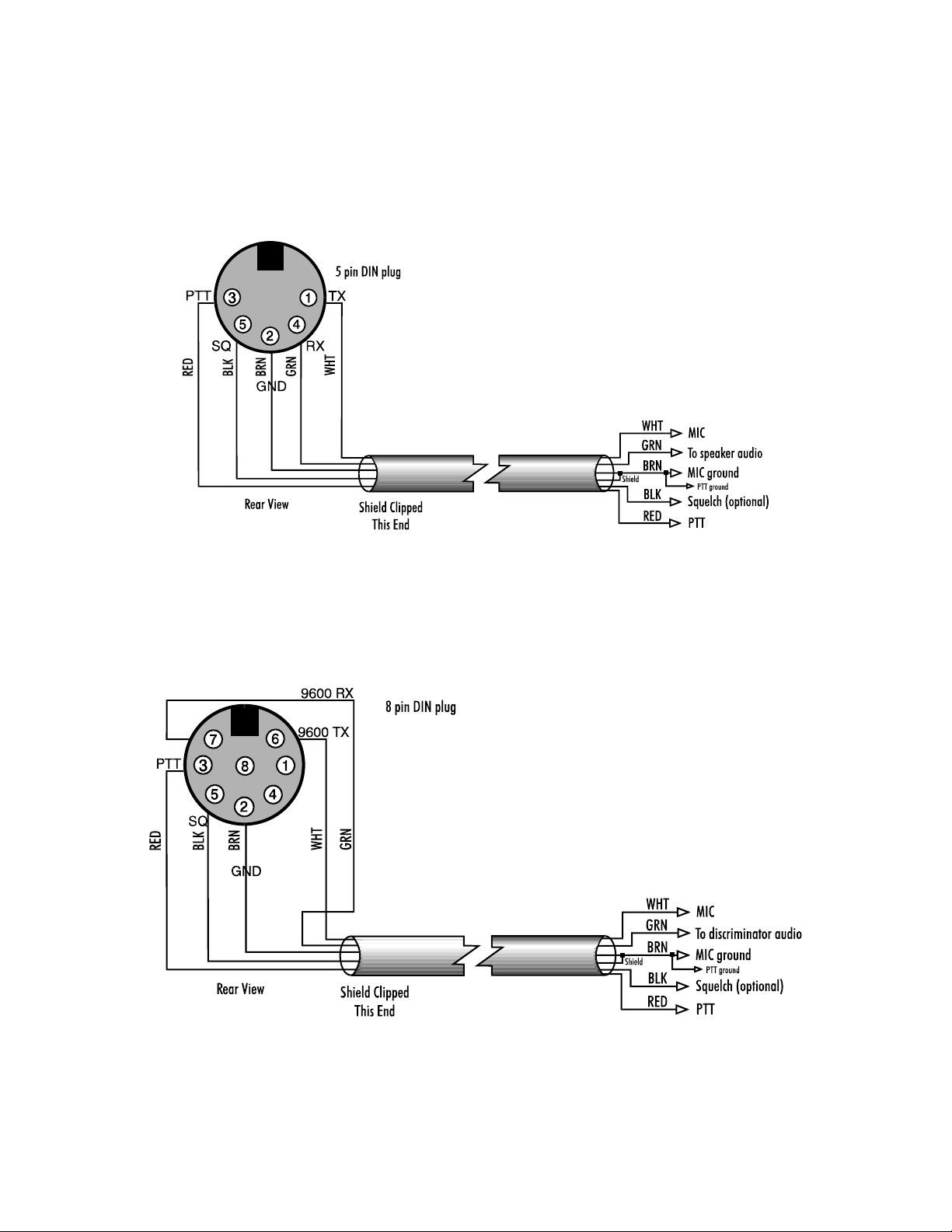
Chapter 3 Radio Installation
Note: If you don’t have a spare receiver to monitor the tone, a “quick-’n’-dirty” way to set the
AFSK level is to turn the AFSK LEVEL pot on the back of the DSP halfway between its stops,
but if you happen to have a deviation meter such as AEA’s DM-1 Deviation Meter, set the AFSK
LEVEL’s pot so the DSP’s deviation is 3.25 KHz, peak.)
2. Verify that your DSP and FM radio(s) are connected as shown in Figure 3-4 and/or 3-5 or 3-6 below.
Figure 3-4 Radio-to-DSP Radio Port 1Connections
Note: Radio Port 2 can be wired the same as Radio Port one (shown above) or it can be wired specifically
for 9600 bps packet operation as in either of the two diagrams shown below. This is the beauty of having
both a 5 Pin and 8 pin DIN, you can fit the 5 pin plug into both ports if you don’t run 9600 bps packet,
and for those you do run 9600 bps you can use Port 2 specifically for this purpose.
Figure 3-5 Radio-to-DSP Radio Port 2 Connection for 9600 bps packet
September, 05 3-5
Page 30
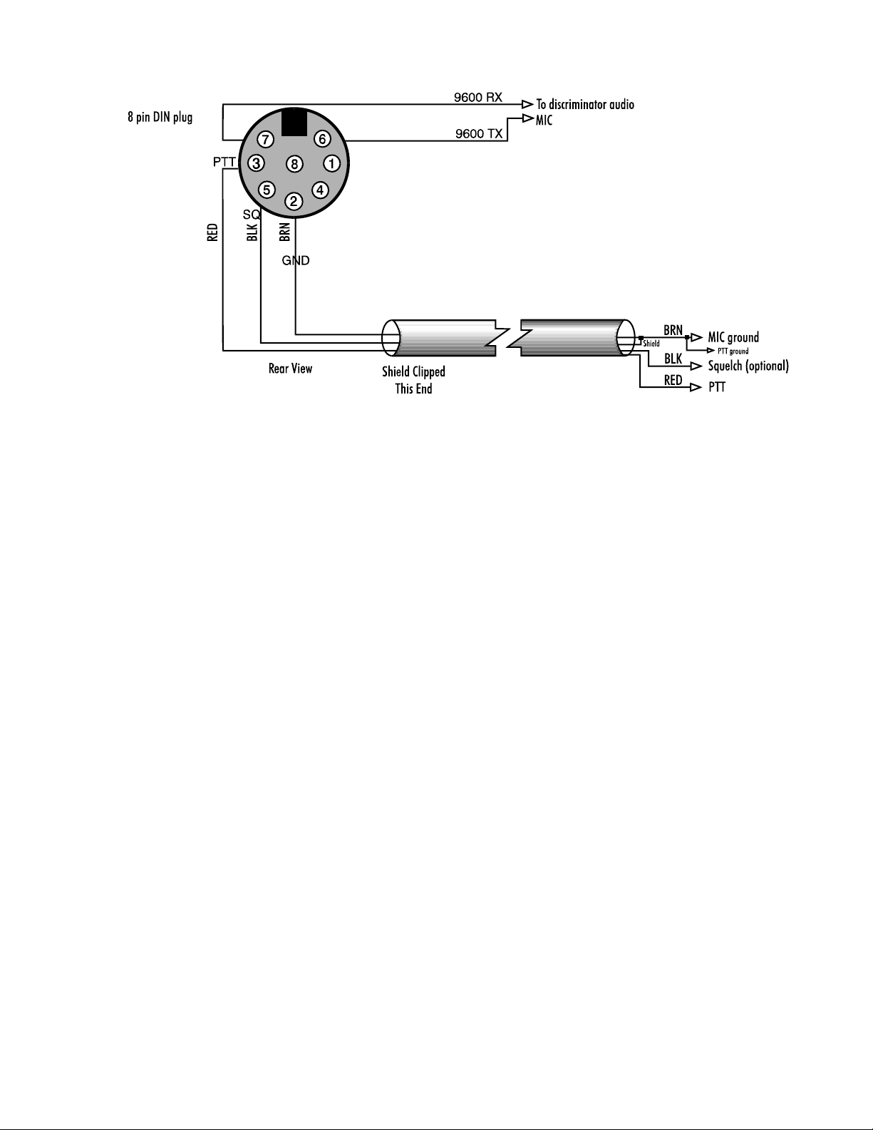
Chapter 3 Radio Installation
Figure 3-6 Radio-to-DSP Radio Port 2 Connection for 9600 bps packet
3. Turn on your radio and computer. Load your terminal program so that you’re operating the DSP in the
Dumb Terminal mode.
4. Enter the CALIBRATE mode by entering: CAL next to the cmd: prompt.
In the CALIBRATE mode only, the letter K toggles the transmitter PTT line on and off; the (SPACE) bar
toggles the tone generator from Mark (the lower pitched tone) to Space (the higher pitched tone).
Note: The DSP has a transmit watchdog timer circuit that unkeys your transmitter automatically
after 30 seconds.
5. Press K to key the transmitter. You should hear a continuous tone in the spare receiver.
6. Tap the (SPACE) bar several times until the higher pitched of the two tones (Space) is heard.
7. Adjust the transmit audio level as follows:
a) Set the monitor receiver to your transmitter’s frequency and turn up the volume. Turn the DSP’s rear-
panel AFSK LEVEL pot clockwise until you hear no increase in the audio output level from the
monitoring receiver.
b) Rotate the AFSK LEVEL pot counter-clockwise (CCW) until the audio signal on the monitoring
receiver is slightly, but noticeably, reduced.
Note: If you find the “correct” AFSK level setting occurs in the first 20% of the potentiometers range,
the adjustment may be difficult. If you find this adjustment difficult, the internal AFSK
adjustment level jumper may be moved to the LOW setting which will improve the adjustment
range of the potentiometer.
To locate the internal AFSK level jumpers in the DSP-232, remove the six screws that secure the
top chassis, and carefully remove it.
Look for jumpers JP10 and JP11 near the fuse at the rear of the DSP-232 as shown in figure 3-6
below. Jumper JP10 controls the output level of radio port 1, and JP11 controls the output level
of port 2. When the jumper is towards the right, the output level is high (high and low are printed
on the circuit board near the jumper for your convenience). Move the jumper for the radio port
3-6 September, 05
Page 31

Chapter 3 Radio Installation
being adjusted to the left two pins to set the AFSK output level to LOWer range. Repeat step 7
when this has been completed.
Figure 3-6 DSP-232 AFSK HIGH/LOW Jumpers
8. Press K to return to receive mode.
9. Press Q to leave the CALIBRATE mode.
10. Enter the packet mode and set HBAUD to 1200 baud. With your radio in the receive mode, set its squelch
control “open” so that a steady hash or “white noise” is heard from its speaker.
Note: the front panel DCD LED should not be lit.
11. Set the frequency of your FM transceiver to a packet frequency and observe the DCD LED.
12. The DCD LED should light steadily during reception of packets and go out when the channel is clear.
13. This is the proper setting for packet operation. You may now reset your receiver’s squelch for normal voice
operation.
SSB Transceiver Final Adjustments
Digital modes with an SSB radio require specific settings of the radio’s operating controls for proper AMTOR and
Packet operation. Be sure to observe the following settings precautions:
♦ Set VOX to OFF
♦ Set speech compression to OFF
♦ Set AGC to FAST (if available)
♦ Disconnect the ALC cables between your SSB radio and an external RF amplifier
Baudot, ASCII RTTY, Mode B (FEC) AMTOR, and PACTOR send cause continuous, key-down conditions during
the entire length of each transmission. If your SSB radio isn’t designed for continuous transmit operation, you must
operate your radio at a reduced power level. Consult your radio’s specifications for details regarding the operating
“duty-cycle".
September, 05 3-7
Page 32

Chapter 3 Radio Installation
Note: make all connections with all power off.
1. Connect your fabricated cable from the DSP’s RADIO 1 or RADIO 2 connector to your SSB radio.
2. Connect your SSB radio to a dummy load.
3. Turn on your computer, start its terminal program, enter its Dumb Terminal mode, then turn on the DSP.
4. If your SSB radio has a “monitor” facility that lets you listen to the audio signals entering the microphone
or phone patch jacks, turn that monitor circuit on.
5. Switch the radio to LSB (lower sideband).
6. Set the radio’s Meter switch to the ALC position. If the radio doesn’t have an ALC indication, set the
meter switch to I
to indicate power output.
7. Enter the CALIBRATE mode by entering: CAL
Note: In the CALIBRATE mode only, the letter K toggles the transmitter PTT line on and off;
the (SPACE) bar toggles the tone generator from Mark (the lower pitched tone) to Space (the
higher pitched tone).
The DSP has a transmit watchdog timer circuit that unkeys your transmitter automatically after thirty (30)
seconds.
8. Rotate the microphone gain control CCW so it’s off.
9. Press K to key the transmitter. Increase the microphone gain control clockwise until hear a continuous tone
from the radio’s monitor output (through the radio’s speaker or headphone jack.)
10. Tap the Space Bar several times until the lower pitched of the two tones (Mark) is heard.
11. Rotate the microphone gain control clockwise from its OFF position about a quarter turn.
12. Turn the DSP’s rear-panel AFSK LEVEL pot CW until the ALC meter shows a small deflection from its
unmodulated mark. Check the radio’s plate/collector current or output power indicators.
13. Adjust the AFSK LEVEL control until the radio’s indicators show approximately thirty percent (30 %) of
the manufacturer’s rated full-power reading.
Example: If the manufacturer’s plate/collector current specification for clockwise operation is 200 mA, set
the AFSK LEVEL pot and your microphone gain control so that the plate/collector current indicates
approximately 75 mA.
14. Press K to return to receive mode.
15. Press Q to “Quit” (exit) the CALIBRATE routine.
16. Remove the dummy load and connect your antenna line. Then, tune your radio to a clear, unoccupied
frequency.
17. Set the receiver’s audio volume control (AF GAIN) to the position you would normally use for CW
reception. This is the approximate receiver audio output level for best receive performance from your
DSP’s modem.
or IC to read the plate/collector current. If a current reading isn’t available, set the meter
P
3-8 September, 05
Page 33

Chapter 3 Radio Installation
18. Adjust the software controlled THRESHLD (default 50) up or down until the DCD light is lit by the noise
output from your receiver, then increase it slowly until the DCD light is no longer lit. Alternatively, you
can type AUTOTHR at the cmd:, and the DSP will automatically adjust the threshold to the proper
setting.
September, 05 3-9
Page 34

Chapter 4 Terminal Interfacing
Chapter 4
Terminal Commands
Overview
We know you’re ready to get on-the-air, but before you do you should familiarize yourself with the DSP-232’s
“operating system,” a few important commands, some error messages, and its list of available commands.
Most of the commands have a standard (default) value that provide good performance for the mode you select and
for an average amateur radio station. Almost all of the commands have initial or default values that are loaded when
the DSP is first turned on, but there’s no rule that says “you must keep these defaults.” You can—and should—
change the default values as required for your individual operating needs, type of equipment, and local operating
practices or protocols.
Don’t be daunted by all the commands that are available to you—an average user needs to understand or change
only a handful of them and once set, usually don’t need to be reckoned with again. (See EXPERT.) This chapter
describes the commands used to control how the DSP-232 communicates with your terminal or PC. Mode specific,
MailDrop, and GPS commands are listed and explained in their respective chapters elsewhere in this manual.
There are five TNC control modes you need to be familiar with to make the DSP-232 communicate with your
terminal. These are: the Command mode, Converse mode, Transparent mode, Host mode, and KISS mode. Below is
a brief desicription of each of these modes. Later in this chapter are the actual commands that you will use to enable
the TNC to communicate with the terminal.
Command Mode
Command mode is for configuring and setting the parameters for your TNC. To get to the Command mode if you
are in the Converse mode, enter a <CTRL> C. If you are in any of the other operating modes, you can get to the
Command mode by entering three <CTRL> C’s in quick succession.
Once in the Command mode you will see this— cmd:. You type the system parameters at the cmd: prompt. You
will see what you type on the screen, and if you type something wrong, the system will try to help you through the
mistake. For example, if you type the wrong type of arguement, such as a numeric value instead of a text arguement,
the TNC will respond with— What? If you type a numeric value that is out of the command’s range, the system
will respond with— Range? See the parameters and arguements explaination below for more information on how
to deal with the command arguements. To get a complete list of the TNC’s parameters type Disp Z at the cmd:
prompt.
Converse Mode
Converse mode is for communicating with someone on the air. Whatever you type on your keyboard will be
transmitted by your radio. To enter the Converse mode, type CONVERSE or K at the cmd: prompt.
Once in the Converse mode you will see a cursor on the left-hand side of your screen. As stated previously,
whatever you type will be transmitted. You can make changes as to the way your typed messages are transmitted.
For example, you can change the settings so that an entire line will be transmitted after a carraige return as opposed
September, 05 4-1
Page 35

Chapter 4 Terminal Interfacing
to character by character --these sort of configuration changes are made in the Command mode and are realized in
the Converse mode.
Transparent Mode
Transparent mode is used to transfer binary files. No data is echoed, so you don’t see the actual data appearing on
your screen. The TRANS command switches the DSP-232 from the Command mode to the Transparent mode.
Host Mode
In Command mode, the DSP-232 presents a reasonably user-friendly human interface that uses plain-language to
describe exactly what is going on.
All of the DSP-232’s Command mode features that make life easy for the user unfortunately produce substantial
difficulties for the computer and for the programmers that write terminal control programs.
Host mode does not use human-type dialog. By communicating directly with the ‘host’ or computer, Host mode
provides the computer with much greater direct control over the DSP-232. Host mode permits programmers to
eliminate, reduce, or greatly simplify the transfer and subsequent encoding and decoding of critical information. In
Host mode, the DSP-232 is unfriendly; humans would find it difficult to operate the DSP in Host mode.
KISS Mode
The DSP-232 provides a simple, asynchronous, computer-to-TNC protocol for a raw HDLC TNC or “KISS” TNC
developed by Phil Karn (KA9Q). The computer must provide all AX.25 headers and timing functions. KISS
protocol is similar to the Raw HDLC protocol where data from the computer is converted into pure packet frames
without adding headers or protocol bytes. However, Raw HDLC is available only in Host mode, whereas KISS is its
own mode.
Parameters and Arguments
If a command requires an argument, the type of argument is indicated after the command name as well as its default
value. There are three different types of parameters used: Boolean, Numeric, and Text.
Boolean
Boolean arguments use one value out of a choice of only two possible values, such as ON or OFF, YES or NO, or
EVERY or AFTER. Boolean arguments can also be changed back and forth (toggled) with an argument of
TOGGLE or T. This is useful, for example, in the case of RXREV and TXREV.
Numeric
An argument designated as “n” is a numeric value. Numeric values can be entered by typing them in familiar
decimal numbers, or in hexadecimal numbers. When using hexadecimal notation, you must type a $ in front of the
number to tell the DSP that this is a “hex” number.
For numeric parameters the arguments ON or Y set the parameter value to its default. Arguments OFF or N set the
value to zero. The UP (U) or DOWN (D) can be used to select the next higher or lower baud rate.
Text Arguments
A text parameter, such as the CTEXT message, can hold most any ASCII character including uppercase and
lowercase letters, numbers, spaces, and punctuation.
Some commands, such as CONNECT, require callsigns as arguments. These arguments are usually callsigns, but
may be any string of numbers of at least one letter (and up to six characters) in length. Some commands, such as
CFROM, have arguments which are actually lists of callsigns. You must separate multiple callsigns with either
spaces or commas.
Changing Commands
4-2 September, 05
Page 36

Chapter 4 Terminal Interfacing
As you skim through the list of commands, you’ll notice that the first few characters in the command are capitalized
and the rest aren’t. The capitalized letters indicate the minimum abbreviation for a command. For example, with the
command DISPlay, DISP, DISPL, DISPLA and DISPLAY will all be accepted. You can also enter commands
using lowercase, uppercase, or a combination of lowercase and uppercase letters. Most people find it preferable to
enter their commands in lowercase, but for emphasis the commands in this manual are printed in uppercase.
When you change a command’s value, the DSP will let you know a change has been made and the change will be
automatically saved and an appropriate response will be generated. Say you want to enter your callsign. You’d enter
your callsign after the cmd: prompt by typing MYCALL [call]. If your callsign is WF7A, then this is what you’ll
type:
cmd: MY WF7A
The DSP’s response will be:
MYcall: was DSP232
MYcall: now WF7A
cmd:
If you turn off or remove the power cord from your DSP, it will still remember the change(s) you’ve made. Also, all
commands that accept values or parameters may be typed without any arguments to check their present setting. For
example, if you enter EXPERT after the cmd: prompt, you’ll see:
cmd: EXPERT
cmd: Expert ON
This means that the DSP is currently set to use VHF (or UHF) tone pairs.
If, while changing timing commands and such, you find that you’ve “dug yourself into a hole” and the DSP doesn’t
work as well as it did before, enter REINIT—it’ll reinitialize most of the commands to their default settings and
perform a RESTART, but it won’t lose the contents of the MailDrop or NAVTEX message history.
List of General and Terminal Related Commands
Commands are listed alphabetically with their descriptions. Each command entry contains several fields of
information: Command Name, Default Value, Mode(s) in which the command is used, Host mode abbreviation (for
Host mode programmers), and Parameters. The default value is listed first.
5Bit Immediat e Command
Host: 5B
5BIT is an immediate command allowing the user to store 5-bit Baudot transmissions received then write a program
to decrypt codes that involve bit inversion or transposition. In 5BIT, a constant of $40 (64 decimal) is added to each
received 5-bit character to make it a printable ASCII character in the range of $40-5F. All characters are treated this
way, including CR, LF, LTRS, and FIGS.
When the user enters 5BIT, the DSP-232 displays “OPMODE now BAUDOT”. This is not strictly true; however, the
‘b’ for Baudot will glow in the Mode window.
RXREV, RBAUD, and the MODEM number must be set properly for the monitored transmission. SIGNAL is
helpful in determining whether a transmission is 5-bit and the setting for RBAUD and RXREV, but typing OK after
SIGNAL selects BAUDOT, not 5BIT.
Do not change modes directly between BAUDOT, 5BIT, and 6BIT. Go through some other mode first, such as
Packet. There commands do not function in 5BIT: BITINV, CODE, MARSDISP, TRACE, USOS, WRU, and
XMIT.
6Bit Immediat e Command
Host: 6B
September, 05 4-3
Page 37

Chapter 4 Terminal Interfacing
Same as 5BIT, except that the unit receives a 6-bit code and adds a constant of $30 (48 decimal) to yield a range of
$30-6F. RXREV and RBAUD must be set correctly. SIGNAL is helpful in determining whether a transmission is 6bit and the settings for RBAUD and RXREV, but OK will not automatically select 6BIT.
When the user enters 6BIT, the DSP-232 displays “OPMODE now BAUDOT”. This is not strictly true; however, the
‘b’ will glow in the Mode window.
Do not change modes directly between BAUDOT, 5BIT, and 6BIT. Go through some other mode first, such as
Packet. There commands do not function in 6BIT: BITINV, CODE, MARSDISP, TRACE, USOS, WRU, and
XMIT.
ACRDisp n Default: 0
Host: AA
“n” 1 to 255 specifies the screen width, in columns or characters.
0 Disables this function.
The numerical value “n” sets the terminal output format for your needs. The DSP sends a (RETURN) + [LF is
optional] (LF) sequence to your computer at the end of a line in the Command or Converse modes when “n”
characters have been printed on the computer screen. Most computers and terminals do this automatically so
ACRDISP defaults to 0.
When the DSP is in the MORSE mode, received data will be broken up on word boundaries, if possible. At a
column of 12 less than the ACRDISP value, the DSP starts looking for spaces in the received data. The first space
received after this column forces the DSP to generate a (RETURN). If ACRDISP is 0 (default), this occurs at
column 60. If there are no spaces at—or after—this column, then a (RETURN) occurs at ACRDISP.
For example: pretend you’re sitting in front of typewriter and you set it’s right-margin at 60 (characters). This is
like setting ACRDISP to 60. As you reach, and pass, character 48—the “12 less than ACRDISP” value—the DSP
will look for a space between the words you’re typing in. When it sees this space, it’ll force a (RETURN) to put
you on the next line. If the DSP doesn’t find any spaces between 48 and 60, or if ACRDISP is set to zero, it’ll force
a (RETURN) at 60.
ADDress n Default: $0000
Host: AE
“n” Zero ro 65,535 ($0 to $FFFF) setting and Address in the DSP-232 memory.
The ADDRESS sets an address somewhere in the DSP-232’s memory map. This command is usually used with the
IO, MEMORY and the PK commands. It is used primarily by programmers and is of no use for normal DSP-232
operation.
AFilter ON|OFF Default: OFF
Host: AZ
ON The ASCII characters in the MFILTER list are filtered out and not transmitted.
OFF The ASCII characters in the MFILTER list are filtered from monitored packets only.
Some terminals and computers use special characters to clear the screen or perform other “special” functions.
Placing these characters in the MFILTER list, and turning AFILTER ON, will keep the DSP from transmitting
them.
! Exception: when ECHO is ON and the computer sends a filtered character, the DSP will echo it back to your
terminal or computer.
4-4 September, 05
Page 38

Chapter 4 Terminal Interfacing
AFILTER works regardless of mode, or COMMAND/CONVERSE/TRANSPARENT status. Leave AFILTER OFF
during binary file transfers.
ALFDisp ON|OFF Default: ON
Host: AI
ON A line feed is sent to the terminal after each (RETURN).
OFF A line feed isn’t sent to the terminal after each (RETURN).
ALFDISP controls the display of (RETURN) characters received, as well as the echoing of those that are typed in.
With ALFDISP ON, the DSP adds a line feed (LF) to each (RETURN) it sends to the terminal, if needed. If an LF
was received either immediately before or after a (RETURN), ALFDISP won’t add another LF. Use the DSP’s
sign-on message to determine how (RETURN)s are being displayed.
Note: ALFDISP affects your display, not transmitted data.
♦ Turn ALFDISP ON if the DSP’s sign-on message lines are typed over each other.
♦ Turn ALFDISP OFF if the DSP’s sign-on message is double spaced.
♦ ALFDISP is set correctly if the DSP’s sign-on message is single spaced.
ANalog Immediat e Command
Host: An
ANALOG is an immediate command that switches your DSP-232 into the ANALOG mode.
Most DSP users will not use this mode the way Packet and Baudot are used. Rather, application display programs
will use this mode to process FAX signals, allowing gray scale and color images to be displayed. The Analog mode
paases data for communications modes that require “gray scales” such as FAX. ANALOG is simplar to the
DSPDATA mode, except that in ANALOG the unit samples on a timer interrupt. (Also see the ANSAMPL
command)
Analog requires an 8-bit Analog type of DSP modem that samples and digitizes the analog information. After the
signal is sampled, it is sent to the RS-232 serial port to the host computer for processing.
Presently, Modems 17, 18, and 19 are available for use in the Analog mode. Modem 17 is designed for HF FM
facsimile operation and digitizes the audio frequencies from amplitude of a 1,300 Hz to 2,100 Hz. Modem 19 is
designed for HF FM facsimile operation and digitizes audio frequencies from. Modem 18 is designed for satellite
APT facsimile operation and digitizes the 2,400 Hz audio carrier.. All Analog modems digitize the samples into b
bit binary quantities with the lowest frequency or amplitude represented by $00 and the highest represented by $FF.
Analog modems may also be used in the DSPDATA mode.
To use the Analog mode, the computer program should first ANSAMPLE, then enter ANALOG mode. ANALOG
initializes in the standby receive state. The following commands function in other operating modes and now control
the ANALOG mode as well.
L (Lock): Force Data receive. (Start the Digitizing Process)
R (Receive): Standby receive. (Stop the Digitizing Process)
X (Xmit): Data transmit. (Not yet implemented)
The TRACE command also functions in Analog mode. TRACE OFF (default) sends the data as one binary
character per sample. TRACE ON causes the data to be sent to the user as a 2 hex characters per sample for test
purposes. User BIT 20 (UBIT 20) also affects the data presentation.
ANSample n Default: 2000
Host: As
“n” 900 to 65535 decimal specifies a number to be loaded into the DSP to control the Analog mode sample rate.
September, 05 4-5
Page 39

Chapter 4 Terminal Interfacing
The value n is sent directly to the DSP chip to control the sample rate of the ANALOG mode.
AUTOBaud ON|OFF Default: OFF
Host: AB
ON Autobaud routine always present at power-up or RESTART.
OFF Autobaud routine active at RESET or power-up only if battery jumper is removed.
With AUTOBAUD OFF, the DSP performs the autobaud function only when powering-up or after a RESET. With
AUTOBAUD ON, the DSP performs the autobaud routine every time it’s powered-up, and every time the
RESTART command is entered. The stored parameters (for example, MYCALL) are saved if the battery jumper is
connected. The unit displays the autobaud message at the same rate as the last setting of TBAUD. AUTOBAUD ON
is helpful when moving the unit from one computer to another where the terminal data rates are different.
In the autobaud routine, only one asterisk (*) is needed to set TBAUD. The autobaud routine detects 110, 300, 600,
1200, 2400, 4800, 9600, and 19,200 baud at either 7 bits even parity or 8 bits no parity.
AUTOThr Host: AU
The AUTOThreshold command is used to automatically find the correct threshold setting for the Packet, Pactor,
Amtor, and Morse modes.
To use Autothreshold, tune your radio to a frequency with no signal (make sure the frequency of the radio
corresponds to your currently selected operating mode). Type AUTOT in command mode. The DSP will find the
correct threshold setting using a range from 0-100. If you switch to another mode, you will need to use AUTOT for
this mode as well. Also see the THRESHLD command for manually setting the Threshold.
AWlen n Default: 7
Host: AW
“n” 7 or 8 specifies the number of data bits per word.
The parameter value defines the digital word length used by the serial input/output (I/O) terminal port and your
computer or terminal program.
AWLEN will most likely be set properly by the DSP’s autobaud routine. Still, you may want to chan ge the ASCII
word-length at some time to accommodate a particular terminal program you want to use.
For plain text conversations with the DSP, AWLEN 7 or 8 may be used. For Transparent mode binary file transfers
and Host mode operation, AWLEN 8 must be used.
The RESTART command must be issued before a change in word length takes effect. Don’t change AWLEN
unless the terminal can be changed to the same setting.
BKondel ON|OFF Default: ON
Host: BK
ON The sequence BACKSPACE - SPACE - BACKSPACE is echoed when a character is deleted from the
input line.
OFF The backslash character ( \ ) is echoed when a character is deleted.
4-6 September, 05
Page 40

Chapter 4 Terminal Interfacing
t
BKONDEL determines how character deletion is displayed in the Command or Converse mode. With BKONDEL
ON, the (BACKSPACE) + (SPACE) + (BACKSPACE) sequence is produced which updates your computer
screen, erasing the character you want to delete.
On a printing terminal, the (BACKSPACE) + (SPACE) + (BACKSPACE) sequence will result in overtyped text.
Set BKONDEL OFF if you have a paper-output display, or if your terminal doesn’t respond to the BACKSPACE
character, ^H (CTRL-H). When BKONDEL is OFF, the DSP displays a backslash for each character you delete.
You can get a display of the corrected input by typing the REDISPLAY-line character.
CALibrate Immediat e Command
Host: Not Supported
CALIBRATE is an immediate command that starts the AFSK transmit tone calibration routine. The DSP-232
provides a continuous on-screen display of AFSK generator tone frequencies in Hertz. The Calibrate command
simplifies transmitter calibration of AFSK levels.
When Calibration is checked all packet connections will be lost, and the time-of-day clock will not advance until
you quit the calibration routine.
Commands available in the calibration routine are:
K Toggles the DSP-232’s PTT between on and off.
Q Quits the calibration routine.
<space> Toggles the audio tone between “mark” (low) and “space” (high) tones.
D Toggles between transmitting a continuous tone or alternating the mark and space tones at a rate set by
the radio baud (Hbaud) rate.
CANline n Default: $18 (CTRL-X)
Host: CL
“n” 0 to $7F (0 to 127 decimal) specifies an ASCII character code.
The argument “n” is the ASCII code for the character you want to use to cancel the line of text you’re typing. You
can enter the code in either hex or decimal.
Say you type some characters or a sentence that you want to erase and haven’t yet pressed the (RETURN) key.
Simply enter (CTRL-X). If you plan to assign a different ASCII character, you’d still press the (CTRL) key first,
then the ASCII character you’ve chosen for CANLINE. For example, say you want to assign $7E (~) as your
CANLINE character. Enter:
cmd: CAN $7E
So, when you want to cancel a line of text while in the Command mode, you’d enter ~.
When you use the CANLINE character to cancel an input line in the Command mode, the line ends with the
backslash ( \ ) character and a new prompt (cmd:) appears on the next line to accept a new command. When you
cancel a line while in the Converse mode, only a ( \ ) and a new line appears.
! Remember:
♦ You can cancel only the line you’re currently typing.
♦ Once (RETURN) has been pressed, you can’t cancel the line of text you just typed in.
Note: If your SENDPAC character isn’t RETURN, the CANLINE character cancels only the last line of a multi-line packe
CASedisp n Default: 0 (as is)
Host: CX
September, 05 4-7
Page 41

Chapter 4 Terminal Interfacing
“n” 0 to 2 specifies how your DSP sends characters to your terminal.
CASEDISP allows you to set the case of the characters your DSP sends to your terminal; it offers three possible
modes:
CASEDISP 0 ”As is” - characters’ case isn’t changed.
CASEDISP 1 ”lower” - all characters are displayed in lowercase only.
CASEDISP 2 ”UPPER” - all characters are displayed in uppercase only.
CASEDISP has no effect on transmitted data from your DSP.
CMdtime n Default: 10 (1000 msec.)
Host: CQ
“n” 0 to 250specifies TRANSPARENT mode time-out value in 100-mS intervals. If “n” is 0 (zero), exit from
the Transparent mode requires sending the BREAK signal or interruption of power to the DSP.
CMDTIME sets the time-out value in the Transparent mode. A guard time of “n” x 10 seconds allows escape to the
Command mode from the Transparent mode while permitting any character to be sent as data.
The same Command mode entry character COMMAND (default CTRL-C) is used to exit the Transparent mode,
although the procedure is different than from Converse mode. Three Command mode entry characters must be
entered less than “n” x 10 seconds apart—with no intervening characters—after a delay of “n” x 10 seconds
following the last characters typed.
The following diagram illustrates this timing:
Last First Second Third DSP now
Terminal Command Command Command in Command
Input Character Character Character mode
| Entry Entry Entry |
| | | | |
| | | | |
| <longer than n> | <shorter than n> | <shorter than n> | <——n——> |
COMmand n Default: $03 (CTRL-C)
Host: CN
“n” 0 to $7F (0 to 127 decimal) specifies an ASCII character code.
COMMAND changes the Command mode entry character. Type the COMMAND character to enter the Command
mode from either the Converse or Transparent mode. After you enter the COMMAND character, the Command
prompt (cmd:) should appear, indicating successful entry into the Command mode. See CMDTIME.
CONVerse ( or K) Immediate Command
Host: Not Supported
CONVERSE is an immediate command that causes the DSP to switch from the Command mode to the Converse
mode. The letter K may also be used.
Once the DSP is in the Converse mode, all the characters typed into the keyboard are transmitted by your radio. To
return the DSP to the Command mode, type the Command mode entry character, (CTRL-C).
CUstom n Default: $0A15
Host: Cu
4-8 September, 05
Page 42

Chapter 4 Terminal Interfacing
“n” 0 to $FFFF (0 to 65,535 decimal) specifies a four-digit hexadecimal value, where each bit controls a
different function described below.
CUSTOM was originally introduced to allow specialized features for custom applications to be added to AEA Data
Controllers without burdening you with extra commands. Since the CUSTOM command is quickly filling up, UBIT
has been added to replace CUSTOM to allow for additional features. The CUSTOM command is retained for
compatibility, but we recommend using the UBIT command as it’s more flexible and easier to use.
For those applications that can’t take advantage of the UBIT command, the following terminal-related CUSTOM
features are available in the DSP-232. See Appendix C for a complete list.
Bit2, position $0004: If bit 2 is set to 1, (default), a break on the RS-232 line will put the DSP into the
Command mode (except for Host mode). If set to 0, a break on the RS-232 line will
not affect the DSP.
Bit 5, position $0020: If bit 5 is set to 0, (default) the DSP will always power up in the Command mode. If
bit 5 is set to 1, then the DSP will remain in the previous mode, that is, Converse,
Command, or Transparent mode.
Bit 14, position $4000: If bit 14 is set to 0 (default), the transmit buffer for data sent from the computer to the
DSP is limited only by the DSP memory. If bit 14 is set to 1, the serial flow control
will permit only a maximum of 7 I-frames to be held by the DSP before transmission.
This solves a problem with the YAPP binary file transfer program which relies on a
small TNC transmit buffer to operate correctly.
Bit 15 is unused at the present time. To (RETURN) CUSTOM to the default setting, type CU Y or CU ON at the
command prompt.
DAYStamp on/off Default: off
Host: DS
on The DATE is included in CONSTAMP and MSTAMP displays.
off Only the TIME is included in CONSTAMP and MSTAMP displays.
DAYSTAMP activates the date in CONSTAMP and MSTAMP. Set DAYSTAMP ON when you want a dated
record of packet channel activity, or when you’re available for local packet operation.
DAytime date and time Default: none
Host: DA
date and time Current d ate and time used to set the DSP’S internal clock.
DAYTIME is used in many modes and should be set when the DSP is initially powered up.
The clock isn’t set when the DSP is first turned on. The DAYTIME command displays the ?clock not set
error message until it’s set as follows:
YYMMDDHHMMSS
Example: cmd: daytime 951125065923
September, 05 4-9
Page 43

Chapter 4 Terminal Interfacing
where: YY is the last two digits of the year 1995
MM is the two-digit month code (01-12) Nov
DD is date (01-31) 25
HH is the hour (00-23) 6 (am)
MM is the minutes after the hour (00-59) 59
SS is seconds (optional) 23
If you want the DSP to keep current time, either keep its power supply on, have the software program you’re using
set the clock upon start-up, or install a dedicated clock chip. The clock chip of choice is the SmartWatch clock chip
(DS1216C) by Dallas Semiconductor, 4350 Beltwood Parkway, Dallas, TX 75244. Phone: (214) 450-0400. (You
can also order the chip from JDR Microdevices, 1-800-538-5000.) The only time the SmartWatch is read is upon
power-up, RESTART or RESET.
Installation is easy: Carefully remove U5, install the SmartWatch chip into U5’s socket, then insert U5 into the top
of the SmartWatch chip. Enter the time and date in DAYTIME and you’re all set.
DELete ON|OFF Default: OFF
Host: DL
ON The DELETE ($7F) key is used for editing your typing.
OFF The BACKSPACE ($08) key is used for editing your typing.
Use the DELETE command to select the key to use for “backing up” and deleting text.
Refer to BKONDEL to see how the DSP indicates deletion.
DIRect “m n” Immediate command
Host: DQ
DIRECT is an immediate command that displays a directory listing of all available DSP-232 Modems. When the
DIRECT command is given, the modem list is displayed as shown below:
The DIRECT command can also take a modem number as an arguement to display only the information on that
particular modem including the argument of 0 which displays only the date of the modem EPROM. A range of
arguments can also be entered, for example DIRECT 1 9 will display the directory of all the RTTY/TOR modems
contain in the MODEM EPROM.
1: FSK 45 bps 2125/2295
2: FSK 100 bps 2125/2295
3: FSK 45 bps 1615/1785
4: FSK 100 bps 1615/1785
5: FSK 200 bps 2110/2310
6: FSK 200 bps 1600/1800
7: FSK 200 bps 2125/2550
8: FSK 200 bps 1275/1700
9: FSK 200 bps 2125/2975
10: FSK 200 bps 1275/2125
11: FSK 300 bps 2110/2310
12: FSK 300 bps 1600/1800
13: FSK 1200 bps VHF
14: PACSAT 1200 bps BPSK
15:
16: FSK 9600 bps K9NG/G3RUH
17: Analog FAX HF 1450/2500 FM
18: Analog FAX APT 2400 Hz AM
19: Zero-Crossing FAX 1300/2100
20: Morse 750 Hz.
21: OSCAR-13 Telemetry 400 bps BPSK
4-10 September, 05
Page 44

Chapter 4 Terminal Interfacing
cmd:
DSPdata Immediate Command
Host: DP
DSPDATA is an immediate command that places the DSP-232 into the DST DATA mode. In this mode, a host
computer program may communicate directly with the Analog Devices 2105 chip. In this mode, the DSP-232 is
functionally only a modem. All protocol conversion or translation of the data must be done by the host computer
program.
The DSP DATA mode is not a mode most users will ever need to use directly. Rather it allows programmers to use
the Modems in the DSP-232 for their own applications.
DISPlay class Immediate Command
Host: Not Supported
class Lists commands and their current settings, depending which argument you enter for class and how
EXPERT is set. When DISPLAY is typed without a parameter, the DSP responds with a short list of oftused parameters.
One of the most important commands is DISP—it generates a list of commands and their saved (current) arguments
or values. To see a brief list, enter DISP. Your screen should now display:
(See also DISPLAY A,B,C,F,I,L,M,R,T,Z)
Connect Link state is: DISCONNECTED
Opmode PAcket
EXPert OFF
FRack 5 (5 sec.)
HBaud 1200
MAXframe 4
Monitor 4 (UA DM C D I UI)
MYcall none
MYSelcal none
PACLen 128
RBaud 45
TXdelay 30 (300 msec.)
Vhf ON
WIdeshft OFF
cmd:
By typing an argument after DISP, like DISP A, you can call up a sub-list with a different set of commands. If you
want to list all of the available commands and their settings, enter DISP Z.
The arguments for class are:
(A)sync displays asynchronous port parameters
(B)BS displays AMTOR and packet MailDrop parameters
(C)haracter displays special characters
(F)ax displays fax parameters
(I)d displays ID parameters
(L)ink displays link parameters
(M)onitor displays monitor parameters
(R)TTY displays RTTY and PACTOR parameters
(T)iming displays timing parameters
(Z) displays the entire command/parameter list
...and here are their default listings, with EXPERT OFF:
September, 05 4-11
Page 45

Chapter 4 Terminal Interfacing
cmd:DISP A
8Bitconv OFF
AWlen 7
PARity 3 (even)
TBaud 1200
cmd:DISP C
CHSwitch $00
PTOver $1A (CTRL-Z)
cmd:DISP G
GENDchar $0D
GINIText
GLOCtx 0 (00 sec.)
GNMEA1 GPGLL (0-8 char.)
GNMEA2
GPSMode 0
GREMprog
GSYMChar
GUNSTart
cmd:DISP I
Unproto CQ
AAb
CMSg OFF
CText
HId OFF
MId 0 (00 sec.)
MYcall WF7A
MYGate none
MYIdent none
MYPTcall none
MYSelcal none
cmd:DISP B
3Rdparty OFF
MAildrop OFF
MDMon OFF
MDPrompt Subject:/Enter message, ^Z
(CTRL-Z) or /EX to end
MMsg OFF
MTExt Welcome to my personal
mailbox.
MYMail none
TMail OFF
TMPrompt GA subj/GA msg, '/EX' to
end.
cmd:DISP F
ASPect 2 (576)
FSpeed 2 (120)
GRaphics 1 (960 dots)
PRCon OFF
PRType 2
cmd:DISP L
Connect Link state is: DISCONNECTED
GUsers 0
HBaud 1200
MAXframe 4
PACLen 128
REtry 10
TRIes 0
USers 1
Vhf ON
XMITOk ON
4-12 September, 05
Page 46

Chapter 4 Terminal Interfacing
cmd:DISP M
CONStamp OFF
DAYStamp OFF
MCon 0 (none)
MDigi OFF
MFIlter $80
Monitor 4 (UA DM C D I UI)
MStamp OFF
WHYnot OFF
cmd:DISP R
ABaud 110
ADelay 4 (40 msec.)
ARXTor OFF
DIDdle ON
EAS OFF
MOPtt ON
MSPeed 20
PT200 ON
PTHuff 0
PTRound OFF
RBaud 45
RXRev OFF
TXRev OFF
USOs OFF
WIdeshft OFF
WOrdout OFF
cmd:DISP T
FRack 5 (5 sec.)
cmd:DISP Z
Lists all the above commands in alphabetical order
PErsist 63
SLottime 30 (300 msec.)
TXdelay 30 (300 msec.)
Echo ON|OFF Default: ON
Host: EC
ON Characters received from the terminal are echoed by the DSP-232.
OFF Characters aren’t echoed.
The ECHO command controls local echoing by the DSP-232 when in the Command or Converse mode, but not in
the Transparent mode.
♦ Set ECHO ON (default) if you don’t see your typing appear on your display.
♦ Set ECHO OFF if you see each character you type twice.
ECHO is set properly when you see the characters you type displayed correctly.
EScape ON|OFF Default: OFF
Host: ES
ON The (ESCAPE) character ($1B) is output as “$” ($24).
OFF The (ESCAPE) character is output as ESCAPE ($1B) (default).
ESCAPE selects the character to be output when an (ESCAPE)character is sent to the terminal. The
(ESCAPE)character selection is provided because some computers interpret the ESCAPE character as a special
command. Set ESCAPE ON if you have an (ESCAPE)-sensitive computer to avoid unexpected results from
accidentally receiving this character.
EXPert ON|OFF Default: OFF
Host: DL
OFF Disable some of the less frequently used commands in verbose mode.
ON Enables all commands in verbose mode.
EXPERT controlls your access to the DSP’s command set. Because some new DSP-232 owners understandably
find the large number of commands confusing or daunting, this command limits the newcomer’s access to the
commands that are the simplest or the most often used. Generally, about half of the total number of commands are
available to you after a RESET (EXPERT OFF).
September, 05 4-13
Page 47

Chapter 4 Terminal Interfacing
With EXPERT OFF, expert-level commands may not be accessed and don’t appear in any output of the DISPLAY
command--an attempt to use one of these commands will result in the error message “?EXPERT command.”
All mmediate commands (e.g., CONNECT and PACKET) are ‘NOVICE’ commands. The error message for an
Expert command is separate from the unknown command message:
cmd: BBQ
?What?
cmd: FRICK
?EXPERT command
In Host mode, all commands are available, regardless of the setting of EXPERT. This command won’t affect
operation of AEA PakRatt programs.
The following display lists denote when a command is available when EXPERT of OFF (“Novice”). “Retain”
means the command keeps its setting during a REINIT operation.
cmd:DISPLAY A
8Bitconv Novice Retain
ACRDisp
AFilter
ALFDisp
AUTOBaud
AWlen Novice Retain
BBSmsgs
CASedisp
DCdconn
Echo
EScape
Flow
ILfpack
NUCr
NULf
NULLs
PARity Novice Retain
TBaud Novice Retain
TRFlow
TXFlow
XFlow
cmd:DISPLAY B
3Rdparty Novice Retain
FREe Retain
KILONFWD Retain
LAstmsg Retain
MAildrop Novice Retain
MDMon Novice Retain
MDPrompt Novice Retain
MMsg Novice Retain
MTExt Novice Retain
MYMail Novice Retain
TMail Novice Retain
TMPrompt Novice Retain
cmd:DISPLAY C
BKondel
CANline
CANPac
CHCall
CHDouble
CHSwitch Novice
COMmand
CWid
DELete
ERrchar
HEReis
PASs
PTOver Novice
RECeive
REDispla
SEndpac
STArt
STOp
TIme
XOff
XON
cmd: DISPLAY F
ASPect Novice
FAXNeg
FSpeed Novice
GRaphics Novice
LEftrite
PRCon Novice
PRFax
PROut
PRType Novice
cmd: DISPLAY I
Unproto Novice Retain
AAb Novice Retain
Beacon
BText Retain
CBell Retain
CMSg Novice
4-14 September, 05
Page 48

Chapter 4 Terminal Interfacing
CText Novice Retain
HId Novice
HOMebbs Retain
MId Novice
MYAlias Retain
MYALTcal Retain
MYcall Novice Retain
MYGate Novice Retain
MYIdent Novice Retain
MYPTcall Novice Retain
MYRemote Novice Retain
MYSelcal Novice Retain
PASSWord Novice Retain
WRu
cmd: DISPLAY L
ACRPack
ALFPack
Ax25l2v2
CFrom Retain
CONMode
CONPerm Retain
DFrom Retain
FUlldup
GUsers Novice
HBaud Novice Retain
LIte
MAXframe Novice
NEwmode
NOmode
PACLen Novice
PASSAll
RAdio Novice
RELink
REMote Novice Retain
REtry Novice
SQuelch
TRIes Novice Retain
USers Novice
Vhf Novice
XMITOk Novice
cmd: DISPLAY M
CONStamp Novice
DAYStamp Novice
HEAderln
MBEll
MBx Retain
MCon Novice
MDigi Novice
MFIlter Novice
MFrom Retain
Monitor Novice
MProto
MRpt
MStamp Novice
MTo Retain
MVia Retain
MXmit
STATus
TRACe
WHYnot Novice
cmd:DISPLAY Q
MODem Novice
QHpacket Novice
QVpacket Novice
QData
QFax
QMORse
QPTor Novice
QRtty Novice
QSignal Novice
QTDm
QTor Novice
cmd:DISPLAY R
ABaud Novice
ACRRtty
ADelay Novice
ALFRtty
ANSample Novice
ARQTmo
ARQTOL
ARXTor Novice
ATxrtty
BItinv
CODe
CRAdd
DIDdle Novice
EAS Novice
MARsdisp
MOPtt Novice
MSPeed Novice
MWeight
NAVMsg Retain
NAVStn Retain
PT200 Novice
PTHuff Novice
PTRound Novice
RBaud Novice
RFec
RFRame
RXRev Novice
SRXall
TDBaud
September, 05 4-15
Page 49

Chapter 4 Terminal Interfacing
TDChan
TXRev Novice
USOs Novice
WIdeshft Novice
WOrdout Novice
XBaud
cmd:DISPLAY S
SCan
STep
STEPLen
STEPRest
STEPSize
STEPUp
cmd:DISPLAY T
ACKprior
AUdelay
AXDelay
AXHang
BXDelay
CHeck
CMdtime
CPactime
DWait
FRack Novice
FRIck
HHang
PACTime
PPersist
RESptime
RQtime
SLottime Novice
TXdelay Novice
TXTail
Commands not displayed:
ADDress
AGc Retain
ALTModem
BARgraph
BRight Novice
CCitt
EXPert Novice Retain
HOST Novice Retain
HPoll Novice
JUstify Novice
KEyword Novice
KIss Novice Retain
KISSAddr
MARK Retain
QWide
RAWhdlc
RKeyword
SEGment
SETPass Novice Retain
SPACe Retain
UBit
UCmd
ZFree
ZStatus
PErsist Novice
Flow ON|OFF Default: ON
Host: FL
ON Type-in flow control is active.
OFF Type-in flow control is inactive.
With FLOW ON (default), any character typed on your keyboard halts the output from your DSP to the computer to
stop until any of the following occurs:
♦ A packet is sent (in Converse mode)
♦ A line is completed (in Command mode)
♦ The packet length (PACLEN) is exceeded
♦ The current packet or command line is canceled
♦ The REDISPLAY character is typed
♦ The packet channel is changed
Setting FLOW ON prevents received data from interfering with your keyboard data entry. With FLOW OFF, data
is sent to the terminal whenever it’s available.
FREe Immediate Command
Host: FZ
4-16 September, 05
Page 50

Chapter 4 Terminal Interfacing
Typing “FREE” displays the number of usable bytes left in the MailDrop, as in “FREE 16996.” This may be useful
to a Host mode application using the MailDrop.
Help Immediate Command
Host: Not Supported
While in Command mode, type H to read the abbreviated on-line HELP file which lists the available modes to you
from your DSP. Your monitor will display the following brief list:
cmd: HELP
AScii AMtor PAcket
BAudot ARq Connect
MOrse AList Disconne
DISPlay FEc MHeard
CALibrat AChg CStatus
NAvtex SIgnal FAx TDm
PACTOr PTConn PTSend PTList
CONVerse Trans
Opmode Xmit Rcve Lock
RESTART RESET MDCheck TClear
Host n Default: 0
Host: HO
“n” A hexadecimal value from $00 through $FF setting bits from the table below that define the Host operation
of the DSP.
The Host command enables the “computer-friendly” Host communications mode over the DSP’s RS-232 link. To
exit out of the Host mode, enter three (CTRL-C) characters in rapid succession or type (CTRL-
A),O,H,O,N,(CTRL-W). Sending a Break signal won’t cause the DSP to exit from the Host mode.
Bit 0: Controls whether the Host mode is ON or OFF.
If bit 0 is equal to 0, Host is OFF.
If bit 0 is equal to 1, Host is ON.
Bit 1: Controls the local MailDrop access.
If bit 1 is 0, then the MailDrop Send data uses the $20 block. Read data uses the $2F block as
before. Monitored MXMIT data uses the $3F (monitored receive) block type.
If bit 1 is 1, then the MailDrop send data uses the $60 block type. Read data uses the $70 block
type. Monitored MXMIT data uses the $2F (echoed) block type to differentiate between monitored
transmitted and received frames.
Bit 2: Controls the DSP-2232 and PK-900 extended Host mode. (This isn’t used in the DSP-232.)
Bits 3-7 are reserved for future use.
To maintain backward compatibility with older programs written to use the ON|OFF form of the Host command,
Host ON is equivalent to Host $01 described above. However, programmers must note that Host now returns a
numeric value and not ON or OFF as before.
HPoll ON|OFF Default: ON
Host: HP
ON The Host mode program must poll the DSP for all data (default).
September, 05 4-17
Page 51

Chapter 4 Terminal Interfacing
OFF The Host mode program must accept data from the DSP at anytime.
With HPOLL ON, the Host mode program must poll the DSP—using (CTRL-A),O,G,G,(CTRL-W)—for all data
that might be available to be displayed to the screen. With HPOLL OFF, the Host mode program must be able to
accept any data from the DSP whenever it becomes available.
KIss n Default: 0
Host: KI
“n” Is a HEX number from $00 (KISS disabled) through $FF that enables the KISS mode selected from the
table below.
The KISS mode must be entered to prepare the DSP for KISS operation. TCP/IP and other special applications have
been written that require the KISS mode be enabled to operate correctly. For normal AX.25 packet operation, this
command should be left at 0 or OFF (default).
The KISS command, formerly ON|OFF, has now been expanded to a numerical value from $00-$FF. This
expansion supports G8BPQ’s multi-drop KISS protocol. The table below describes available KISS options.
KISS $00: KISS disabled (formerly displayed as KISS OFF)
KISS $01: Standard KISS (same as KISS ON or KISS YES)
KISS $03: Extended KISS
KISS $07: Extended KISS+KISS polling enabled
KISS $0B: Extended KISS+KISS checksum enabled
KISS $0F: Extended KISS+KISS polling and checksum enabled
Note that KISS ON enables standard KISS operation for compatibility with existing applications.
Extended KISS
If the KISS checksum is enabled, a checksum byte is added to the end (before the final FEND) of all KISS blocks
flowing between the TNC and the host application. The checksum is the exclusive-OR of all other bytes between
the FEND bytes, taken before KISS escape transpositions. A checksum is helpful when using multiple TNCs on a
marginal RS-232 link. If the DSP receives a KISS block with a bad checksum, it does not transmit the data.
In KISS and Raw HDLC modes, communication activity on the RS-232 link is shown by lighting the STA and
CON LEDs as follows:
Host OFF—entering three (CTRL-Cs)—will force KISS OFF. Details on the use of KISS TNC protocol are
contained in AEA’s Technical Reference Manual — Model DSP-232 Data Controller.
KISSAddr n Default: 0
Host: KA
mode adds these commands to the standard commands ($x0-$x5):
$xC signifies data to be transmitted. Unlike the $x0 command, the $xC byte is followed by two frame ID
bytes, then the data; when the TNC transmits the frame, it notifies the host application by echoing back
FEND, the $xC byte, the two frame ID bytes, and FEND.
$xE is the polling command, similar to the Host “GG” command existing in AEA products. Polling makes
multi-TNC KISS operation possible. If KISS polling is enabled, the TNC holds received data until the host
application sends the poll command. If the TNC is holding no data, it echoes back FEND $xE FEND. The
“x” in “$xE” must match the number in the KISSADDR command for the TNC to respond.
Host to TNC Communication: STA LED illuminated.
TNC to Host Communication: CON LED illuminated.
4-18 September, 05
Page 52

Chapter 4 Terminal Interfacing
“n” Is a number from 0-15, signifying the KISS address of the TNC’s radio port.
Radio port addressing is available in the high nibble of the KISS command byte. The DSP compares the high nibble
of the KISS command byte to KISSADDR only if extended KISS mode is enabled. If the command doesn’t match
KISSADDR, the DSP takes no action. Exception: the exit-KISS command $FF works no matter what the value of
KISSADDR or the status of extended KISS mode.
MEmory Default: none
Host: MM
n A hexadecimal value used to access the DSP-232’s memory locations, or read values stored at a specified
ADDRESS.
The MEMORY command works with the ADDRESS command (ADDRESS $aabb) and permits access to memory
locations. Use the Memory channel without arguements to read a memory, and with one arguement $0 to $FF to
write to a memory location. The value in ADDRESS is incremented after using the MEMORY command.
MODem Default: 12
Host: Mg
n 0 to 21 signifies a modem number from the list below.
The MODEM command determines what DSP Modem is selected for the DSP-232. The Modems available in
EPROM are listed below.
The DSP modems included in the DSP-232 can be shown with the DIRECT(ory) command and are listed below.
1: FSK 45 bps 2125/2295
2: FSK 100 bps 2125/2295
3: FSK 45 bps 1615/1785
4: FSK 100 bps 1615/1785
5: FSK 200 bps 2110/2310
6: FSK 200 bps 1600/1800
7: FSK 200 bps 2125/2550
8: FSK 200 bps 1275/1700
9: FSK 200 bps 2125/2975
10: FSK 200 bps 1275/2125
11: FSK 300 bps 2110/2310
12: FSK 300 bps 1600/1800
13: FSK 1200 bps VHF
14: PACSAT 1200 bps BPSK
15:
16: FSK 9600 bps K9NG/G3RUH
17: Analog FAX HF 1450/2500 FM
18: Analog FAX APT 2400 Hz AM
19: Zero-Crossing FAX 1300/2100
20: Morse 750 Hz.
21: OSCAR-13 Telemetry 400 bps BPSK
cmd:
NEwmode Default: ON
Host: NE
ON The DSP automatically returns to the Command Mode at disconnect or return to receive.
OFF The DSP does not return to the Command Mode at disconnect or return to receive.
September, 05 4-19
Page 53

Chapter 4 Terminal Interfacing
You DSP-232 always switches to a data transfer mode at the time of connection, unless NOMODE is ON.
NEWMODE determines how your DSP behaves when the link is broken or when the state is changed from
Transmit to Receive with the RECEIVE or CWID characters.
When NEWMODE is ON (default) and the link is disconnected, or if the connect attempt fails, your DSP-232
remains in Converse or Transparent Mode unless you have forced it to return to Command Mode.
NUCr ON|OFF Default: OFF
Host: NR
ON Null characters are sent to the terminal following RETURNs.
OFF Null characters aren’t sent to the terminal following RETURNs.
NULLS sets the number of null characters that will be sent. Some older printer-terminals require extra time for the
printing head to do a (RETURN) and LF. NUCR ON solves this problem by making your DSP send null characters
(ASCII code $00) to your computer or terminal.
NULf ON|OFF Default: OFF
Host: NF
ON Null characters aren’t to the terminal following LFs.
OFF Null characters aren’t sent to the terminal following LFs.
Some older printer-terminals require extra time for the printing head to do a (RETURN) and LF. NULF ON solves
this problem my making your DSP send null characters (ASCII code $00) to your computer or terminal. NULLS
sets the number of null characters that will be sent.
NULLs n Default: 0 (zero)
Host: NU
“n” 0 to 30 specifies the number of null characters to be sent to your computer or terminal after a (RETURN)
or LF when NUCR, or NULF, are ON.
NULLS specifies the number of null characters (ASCII $00) to be sent to the terminal after a (RETURN) or LF is
sent. NUCR and/or NULF must be set to indicate whether nulls are to be sent after (RETURN), LF or both. The
null characters are sent from your DSP to your computer only in the Converse and Command modes.
Opmode Immediate Command
Host: OP
OPMODE is an immediate command that shows the DSP-232’s current mode of operation as well as system status.
Opmode also displays the MORSE speed when in Morse mode. Use the OPMODE command at any time when your
DSP-232 is in the Command Mode to display the present operating mode. Here is a typical example:
cmd:o
OPmode AScii RCVE
PARity n Default: 3 (even)
Host: PR
“n” 0 to 3 selects a parity option.
PARITY sets the DSP’s parity for RS-232 terminal according to the table below:
0 = no parity
4-20 September, 05
Page 54

Chapter 4 Terminal Interfacing
1 = odd parity
2 = no parity
3 = even parity
The parity bit, if present, is stripped automatically on input and isn’t checked in Command and Converse modes, but
in Transparent mode all eight bits (including parity) are transmitted.
The change won’t take effect until you enter RESTART. Be sure to change the computer or terminal to the same
parity setting after you’ve entered RESTART.
PASs n Default: $16 (CTRL-V)
Host: PS
“n” 0 to $7F (0 to 127 decimal) specifies an ASCII character code that you can .
PASS selects the ASCII character“n” used for the “pass” input editing commands. The PASS character signals
that the following character is to be included in a packet PACTOR or ASCII text string. For example, if you’re
typing in text and want to enter three RETURNs so you can put a line space between two paragraphs, you’d do this:
“...here’s the end of the first paragraph.” (CTRL-V)+(RETURN)+(CTRL-V) (RETURN)+(CTRL-
V)+(RETURN) .“Now this line will appear after a line space.”
The line will appear at the other station like this:
“...here’s the end of the first paragraph.”
“Now this line will appear after a line space.”
If you had just pressed (RETURN) at the end of the word, “paragraph,” you would’ve forced a packet to be sent.
Press (RETURN) again, and you would’ve forced an empty packet to be sent. Press (RETURN) yet again, and
another empty packet would’ve been sent. This happens because when you press RETURN, it normally forces a
packet to be sent. However, by inserting a (CTRL-V)
(RETURN) in the Command mode and allow it to be used in your outgoing text to act as a “real” (RETURN). So,
the PASS character “hides” the next character’s function.
PK n Default: none
Host: PK
n a hex number used to access the DSP-232’s memory and I/O locations.
PK (Peek/Poke) permits access to memory locations. To use the PK command:
1) Set the memory address into the ADDRESS command.
2) Use the PK command without arguments to read that memory location.
3) Use PK with one argument 0-$FF to write to that memory location.
DSP-232 RAM locations are $8000-$FFFF. ROM begins at $0000. This command is used primarily as a
programmer’s aid and is not needed for normal use.
QData n Default: 21
Host: QA
n Modem number to be selected when the DSP DATA mode is entered.
QDATA sets the DSP-232 modem that will automatically be selected when the DSP DATA mode is entered.
See the DSPDATA and MODEM commands for more information.
before entering a (RETURN), you disable the function of
September, 05 4-21
Page 55

Chapter 4 Terminal Interfacing
RADio n Defau lt: 1
Host: RA
n 0, 1, 2 with 1 meaning Radio Port 1 and 2 meaning Radio Port 2.
The radio command allows the user to control which radio port is selected.
Type RADIO 1 to select Radio Port 1 (default). To select Radio Port 2, simply enter RADIO 2, or RAD 2.
Typing RADIO 0 disables operation of both Radio Ports.
REDispla n Default: $12 (CTRL-R)
Host: RD
“n” 0 to $7F (0 to 127 decimal) specifies an ASCII character code.
REDISPLA changes the redisplay-line input editing character.
Parameter “n” is the numeric ASCII code for the character you’ll use when you want to re-display the current input
line. Type the REDISPLA character to re-display a command or text line you’ve just typed. This can be helpful
when editing a line, especially if your terminal doesn’t support BACKSPACE. It can also be used in packet to
display a packet that might have been received while you were typing. A backslash (\) is appended to the old line,
and the corrected line is shown beneath it.
REINIT Immediat e Command
Host: RI
This is an immediate command that you can use to get out of trouble caused by setting a lot of commands—
especially timing parameters—to strange values. REINIT can be thought of as being halfway between RESTART
and RESET. REINIT re-initializes most of the commands to their default setting, then does a RESTART, but the
contents of the MailDrop and the NAVTEX message history buffers are preserved. The commands that are
preserved are:
MYCALL MYALIAS MYMAIL HOMEBBS MYGATE MYSELCAL
MYALTCAL MYIDENT MYPTCALL UNPROTO AWLEN PARITY
TBAUD BTEXT CTEXT AAB MDPROMPT TMPROMPT
CFROM DFROM MFROM MTO MBX LASTMSG
MTEXT NAVSTN NAVMSG HOST
In Host mode, the REINIT command is acknowledged by a RESTART response (RT).
RESET Immediate Command
Host: RS
RESET resets all of the DSP’s parameters to their default settings and reinitializes the unit. All person alized
parameters, monitor lists and MailDrop messages will be lost.
RESTART Immediat e Command
Host: RT
4-22 September, 05
Page 56

Chapter 4 Terminal Interfacing
RESTART reinitializes the DSP while retaining the settings you’ve changed or entered. The effect of RESTART is
the same as turning the DSP off, then on again. RESTART doesn’t reset the values stored in its battery-backed
RAM.
See RESET.
STArt n Default: $11 (CTRL-Q)
Host: ST
“n” 0 to $7F (0 to 127 decimal) specifies an ASCII character code.
Use the START command to choose the character you want to use to restart output from the DSP to your computer
after it has been halted by entering the STOP character.
See XFLOW.
STOp n Default: $13 (CTRL-S)
Host: SO
“n” 0 to $7F (0 to 127 decimal) specifies an ASCII character code.
Use the STOP command to select character you’ll use to stop output from your DSP to your computer.
See the XFLOW command .
TBaud n Default: 1200 baud
Host: TB
“n” Specifies the data rate your computer uses to talk to the DSP.
Set TBAUD to specify the terminal baud rate to be activated at the next power-on or RESTART. (A warning
message reminds you of this.) Be sure you can set your computer and its communications program for the new rate.
The TBAUD command supports the following serial port data rates: 45, 50, 57, 75, 100, 110, 150, 200, 300, 400,
600, 1200, 2400, 4800 and 9600 baud.
TClear Immediate Command
Host: TC
The TCLEAR command clears your DSP’s transmit buffer on the “Logical Channel” you have selceted and cancels
any further transmission of data when in the Baudot, ASCII, AMTOR or Morse operating modes. In Packet mode,
all data is cleared except for a few remaining packets.
You must be in command mode to use TCLEAR.
THreshld n Default: 50
n 0-100 sets the threshold for the operating modes.
Fifty is the default for the Threshold control. You can manually enter a threshold value. Alternatively, you can use
the AUTOThr command and the DSP-232 will automatically adjust the threshold to the correct setting for the
operating mode you are currently in.
TIme n Default: $14 (CTRL-T)
September, 05 4-23
Page 57

Chapter 4 Terminal Interfacing
Host: TM
“n” 0 to $7F (0 to 127 decimal) specifies an ASCII character code.
TIME specifies which control character sends the time-of-day in the text you type into the transmit buffer or into a
text file stored on disk.
At transmit time, the DSP reads the time-of-day from the DSP’s internal clock then sends the time to the radio in the
data transmission code in use at that time. If DAYTIME hasn’t been set, a (CTRL-T) will cause the DSP to send an
asterisk (*). With DAYSTAMP ON, the date is transmitted with the time.
Note: TIME can’t be embedded in CTEXT, BTEXT, MTEXT or AAB.
Trans Immediate Command
Host: Not Supported
TRANS switches the DSP from the Command mode to Transparent mode; the current state of the radio link isn’t
affected. Transparent mode is primarily useful for computer communications since Transparent mode “human
interface” features such as input editing, echoing of input characters, and type-in flow control are disabled.
♦ Use Transparent mode for transferring binary or other non-text files.
♦ To exit the Transparent mode, type the COMMAND character, (CTRL-C), three times within the time
period set by CMDTIME (default:1 second).
TRFlow ON|OFF Default: OFF
Host: TW
ON Software flow control for the computer or terminal receiving data is enabled in Transparent mode.
OFF Software flow control for the computer or terminal receiving data is disabled in Transparent mode.
With TRFLOW ON, the type of flow control used by the computer receiving data in the Transparent mode is
determined by how START and STOP are set.
With TRFLOW OFF, only “hardware” flow control (RTS, DTR) is available to the computer when receiving data
from the DSP (while in Transparent mode).
With TRFLOW ON, and START and STOP are set to values other than zero, software flow control is enabled for
your computer. The DSP responds to the START and STOP characters while remaining transparent to all other
characters from the terminal.
TWRcv n Default: 50
Host: Tr
n 0-100 adjusts how the DSP-232 manipulates amplitude of received signals on 1200 bps Packet.
Twist receive (TWRcv) allows you to compensate for poor signal reception by adjusting the amplitude of the high
tones. Entering values less than 50 allow you to lower the amplitude of the received signal’s high tone. Entering
values greater than 50 allow you to increase the amplitude of received signal’s high tone.
TWXmt n Default: 50
Host: Tx
4-24 September, 05
Page 58

Chapter 4 Terminal Interfacing
n 0-100 adjusts how the DSP-232 manipulates amplitude of transmitted signals on 1200 bps Packet.
Twist transmit (TWXmt) allows you to compensate for transmitter deficiencies by adjusting the amplitude of the
high tones. Entering values less than 50 allow you to lower the amplitude of the received signal’s high tone.
Entering values greater than 50 allow you to increase the amplitude of received signal’s high tone. This command
allows you to keep high and low signals at their proper levels on the air.
TXFlow ON|OFF Default: OFF
Mode: packet Host: TF
OFF Software flow control for the DSP is disabled in Transparent mode.
ON Software flow control for the DSP is enabled in Transparent mode.
With TXFLOW ON, the setting of XFLOW determines the type of flow control used in the Transparent mode by
the DSP to control transmitted data; with it OFF, the DSP uses only hardware flow control to control transmitted
data. All data that’s sent to the terminal remains fully transparent.
With both TXFLOW and XFLOW ON, the DSP uses the Start and Stop characters (set by XON and XOFF) to
control the input from the computer.
UCmd n x Default: 0
Host: UB
n 0 to 15 specifying a User BYTE that may be set.
x 0 to 255 specifying the value of the specific byte to be set.
The UCMD is an extension of the UBIT command which allows up to 15 commands that take numeric arguments to
be added to the DSP-232 without burdening users with a large number of commands. The functions controlled by
UCMD are things that most users will never have to change. Still they are important enough to some users or
applications programs that we have included them under the umbrella command UCMD.
The following are examples of how to use the UCMD command:
UCMD 2 Returns the present status of UCMD 2.
UCMD 4 5 Sets user command 4 to the value of 5.
UCMD 12 OFF Sets user command 12 to the value of 0.
UCMD ON Restores user command 8 to its default value.
UCMD Shows the setting of the last UCMD entered.
Listed below are the UCMD functions and the default states that presently have been assigned. The default state of
each UCMD is always shown first.
UCMD 0: This is a Pactor command. It sets the number of correct packets in a row that must be received
before generating an automatic request to change from 200 to 100 baud.
UCMD 1: This is a Pactor command. It sets the number of incorrect packets in a row that must be received
before generating an automatic request to change from 200 to 100 baud.
UCMD 2: This is a Pactor command. It sets the number of packets sent in a speed-up attempt.
UCMD 3: This is a Pactor command. It sets the maximum number of Memory ARQ packets that are
combined to form one good packet. When this number is exceeded, all stored packets are cleared
and Memory ARQ is re-initialized.
UCMD 4-15: are unused for now.
UBit n ON|OFF Default: 0
Mode: All Host: UB
“n” 0 to 255 specifying a User BIT that may be set ON or OFF.
September, 05 4-25
Page 59

Chapter 4 Terminal Interfacing
UBIT is an extension of the CUSTOM command which allows up to 255 ON|OFF functions to be added to the
DSP without burdening you with a large number of extra commands. The functions controlled by UBIT aren’t
things that you’ll most likely change—still, they’re important enough to some users or application programs that we
have included them under the umbrella command of UBIT.
The following are examples of how to use the UBIT:
UBIT 5 Shows the present status of UBIT 5
UBIT 1 ON Sets the function controlled by UBIT 1 to ON
UBIT 10 T Toggles the state of the function controlled by UBIT 10
UBIT Returns the state of the last UBIT value that was accessed
Listed below are the terminal relevant UBIT functions and the default state that presently have been assigned. The
default state of each UBIT is shown first. Others are listed in Appendix C.
UBIT 2: ON: A Break signal received on the RS-232 line forces the DSP into Command mode
from all the modes except Host mode.
OFF: A Break signal on the RS-232 line is ignored by the DSP.
UBIT 5: OFF: The DSP will always power up in Command mode.
ON: The DSP will remain in the last mode (Converse, Command or Transparent)
provided the battery jumper enabled.
UBIT 14: OFF: In packet, the transmit buffer for data sent from the computer to the DSP is limited
only by the available DSP memory.
ON: In packet, the serial flow control will permit only a maximum of seven I-frames to
be held by the DSP before transmission. This solves a problem with the YAPP
binary file transfer program which relies on a small TNC transmit buffer to operate
correctly.
XFlow ON|OFF Default: ON
Host: XW
ON XON/XOFF (software) flow control is activated.
OFF XON/XOFF flow control is deactivated - hardware flow control is enabled.
With XFLOW ON, software flow control is in effect—it’s assumed that the computer will respond to the DSP’s
Start and Stop characters defined by the XON and XOFF commands. Similarly, the DSP will respond to the
computers start and stop characters defined by START and STOP.
With XFLOW OFF, the DSP sends hardware flow control commands by way of the CTS line and is controlled by
either the RTS or the DTR line.
XMITOk ON|OFF Default: ON
Host: X0
ON Transmit functions (PTT line) are active.
OFF Transmit functions (PTT line) are diabled.
When XMITOK is OFF, the PTT lines to your transmitter on both Radio Ports are disabled - the transmit function
in inhibited. All other DSP-232 functions remain the same. Your DSP generates anmd sends packets as requested,
but does not key the radio’s PTT line.
Use the XMITOK command to ensure that your DSP does not transmit.
Turning XMITOK OFF can be used to enable full break-in CW operation (QSK) on certain transceivers.
4-26 September, 05
Page 60

Chapter 4 Terminal Interfacing
XOFF n Default: $13 (CTRL-S)
Host: XF
“n” 0 to $7F (0 to 127 decimal) specifies an ASCII character code.
Use XOFF to select the Stop character to be used to stop input from the computer to the DSP.
The Stop character default value is (CTRL-S) for computer data transfers.
XON n Default: $11 (CTRL-Q)
Host: XN
“n” 0 to $7F (0 to 127 decimal) specifies an ASCII character code.
XON selects the DSP Start character that is sent to the computer to restart input from it to the DSP.
The Start character default value is (CTRL-Q) for computer data transfers.
ZFree Immediate Command
Host: ZF
This command is primarily of interest to HOST mode programmers. ZFREE is an immediate read-only command
that returns the amount of data RAM that is available in the DSP-232. n is the number of free internal memory
blocks. Each memory block holds 28 bytes of data.
Use the ZFREE command to avoid the situation in which a host mode application sends a block of data to be
transmitted, but the controller connot issue a data acknowledgement (5F X X 00) to the host computer rith away
because the TNC is too full. The application should not send data to the controller if it would cause the value of
ZFREE to drop below 64. To avoid the transmission of RNR (device busy) packets, the application should make
sure ZFREE does not drop below 128.
Note that ZFREE is different from the FREE command, which shows the number of message bytes available to the
MailDrop. (ZFREE times 28 is always larger than the value of FREE.)
ZStatus Immediat e Command
Host: ZS
This command is primarily of interest to HOST mode programmers. ZSTATUS is an immediate read-only
command. that returns a data byte in hexadecimal indicating the status of the unit as shown in the table below.
BIT Meaning if 0 Meaning if 1
0 Transmit character RTTY & AMTOR characters
buffer is empty are being transmitted
1 No MailDrop command MailDrop command in progress
in progress
2 No MailDrop messages for The MailDrop contains messages
local sysop for local sysop
September, 05 4-27
Page 61

Chapter 4 Terminal Interfacing
3-7 Reserved Reserved
ZSTATUS is meant to be a read-only command for use by host applications in determining the status of the unit,
although the user may write a value to ZSTATUS if desired. Bit 0 shows whether all characters have been
transmitted in non-packet modes. Bit 1 shows whether the maildrop is busy servicing a command such as Read or
List. (Note: bit 1 may show 0 before the hostapplication has polled all the data from a Read or List command out of
one of the unit’s buffers.) Bit 2 shows whether any mail has been sent to the local sysop (same indication as the
front panel MULT bar flashing).
4-28 September, 05
Page 62

Chapter 5 Packet Operation
Chapter 5
Packet Operation
Overview
In the brief time that packet radio has been around, it has grown to become the most popular digital mode found on
the amateur bands today. Although packet can be found on the HF bands, most of the activity lies in the VHF and
UHF FM frequencies. This chapter will begin with general packet operation for the VHF and UHF frequencies, th en
HF packet operation. (If you’re interested in packet just for HF, read the VHF section, first—many of the
commands found there are also used in HF packet.) If you are interested in Global Positioning System (GPS) or
Automatic Packet Reporting System (APRS) applications, refer to Chapter 6: Global Positioning System
Operation. Mailbox information can be found in Chapter 7: Mailbox Operation. Chapter 4: Terminal
Commands will give you information on general DSP-232 commands. The last few pages of Chapter 4 contain a
list of all DSP-232 commands and the page numbers they can be found on.
Before you plunge ahead, a minor “caution”: as you can see below, there are a lot of commands available to you in
this mode, some of them quite esoteric. The average packet user, however, only has to be familiar with about a
dozen commands, and of those most of those only need to be set once. If you’re a newcomer, set the EXPERT
command to its default (OFF) so you can filter out the “complicated” commands that you needn’t concern you rself
with at this time. The commands you should initially familiarize yourself with are: CBELL, CMSG, CONNECT,
CTEXT, DISCONNE, MHEARD, MONITOR, MYALIAS, MYCALL, MYGATE, MYMAIL, PACLEN, and
UNPROTO. Other commands not mentioned here that are useful to a beginner can be found later in this chapter.
Once you’re comfortable with basic packet operation, you might want to explore these commands: 8BITCONV,
ACKPRIOR, ACRPACK, ALFPACK, ALTMODEM, AUDELAY, AX2512V2, AXDELAY, AXHANG,
BBSMSGS, BEACON, BTEXT, CANPAC, CASEDISP, CFROM, CHCALL, CHDOUBLE, CHECK,
CHSWITCH, CONMODE, CONPERM, CONSTAMP, CPACTIME, CSTATUS, DAYSTAMP, DAYTIME,
DCDCONN, DFROM, DWAIT, FRACK, FRICK, FULLDUP, GUSERS, HBAUD, HEADERLN, HID,
HOMEBBS, ID, ILFPACK, KILONFWD, KISS, KISSADDR, LASTMSG, LITE, MAILDROP, MAXFRAME,
MBELL, MBX, MCON, MDIGI, MDMON, MDPROMPT, MFILTER, MFROM, MID, MMSG, MPROTO,
MRPT, MSTAMP, MTEXT, MTO, MXMIT, PACTIME, PASS, PASSALL, PERSIST, PPERSIST,
RAWHDLC, RELINK, RESPTIME, RETRY, SENDPAC, SLOTTIME, SQUELCH, TRACE, TRIES,
TXDELAY, TXFLOW, USERS, WHYNOT, XMITOK. Packet specific commands are listed and defined at the end
of this chapter.
Switching Between Radio Ports
If you are using an AEA PakRatt program designed for the DSP-232, switching between Radio Ports is described in
the program manual. If you are using a computer terminal, terminal program or the “Dumb Terminal Mode” of an
older PakRatt program, this section will describe how to switch between the radio ports.
The RADIO command allows either radio port 1 (default) or radio port 2 to be selected. To operate on radio port 1,
simply type RADIO 1 (or RAD 1) at the DSP-232 command prompt. To select radio port 2, simply type RADIO 2.
September, 05 5-1
Page 63

Chapter 5 Packet Operation
Tuning in Packet Stations—VHF/UHF
The following steps will help you understand what you need to know about moving around in and configuring your
DSP-232. First you have to enter the packet mode—simply enter PACKET (or PA) at the cmd: prompt. The DSP
responds by displaying the previous mode it was in, then its new mode on the computer screen:
cmd: PA
Opmode was (previous mode)
Opmode now PAcket
cmd:
Look at your DSP’s front panel to verify that you're in the packet mode—in the MODE display there will be a ‘P’.
Now enter your callsign using MYCALL. For example, if your callsign is WO6P, then you’d enter:
cmd: MYCALL WO6P
MYcall was DSP232*
MYcall now WO6P
cmd:
! *or AAA if you just came from Chapter 2 (or if don’t have a callsign, yet).
Next, enter VHF ON then (RETURN).
Your monitor should respond with:
Vhf was OFF
Vhf now ON
*** HBAUD now 1200
You are currenty in the DSP-232’s default radio port -- 1, with the default VHF Packet setting -- 1200 bps. You can
change your Radio Port at any time with the RAD command. You can also select other Packet modems that the
DSP-232 contains. If you wish to select a different DSP modem for Packet operation, simply type MODEM
followed by a modem number. The various modems available in the DSP-232 can be seen with the DIRECT(ory)
command. To display all the available modems, simply enter the Command Mode, using (CTRL - C), of the DSP232 and then type DIR as shown.
DIR (RETURN)
The DSP-232 will respond with the following:
1: FSK 45 bps 2125/2295
2: FSK 100 bps 2125/2295
3: FSK 45 bps 1615/1785
4: FSK 100 bps 1615/1785
5: FSK 200 bps 2110/2310
6: FSK 200 bps 1600/1800
7: FSK 200 bps 2125/2550
8: FSK 200 bps 1275/1700
9: FSK 200 bps 2125/2975
10: FSK 200 bps 1275/2125
11: FSK 300 bps 2110/2310
12: FSK 300 bps 1600/1800
13: FSK 1200 bps VHF
14: PACSAT 1200 bps BPSK
15:
16: FSK 9600 bps K9NG/G3RUH
17: Analog FAX HF 1450/2500 FM
18: Analog FAX APT 2400 Hz AM
5-2 September, 05
Page 64

Chapter 5 Packet Operation
19: Zero-Crossing FAX 1300/2100
20: Morse 750 Hz.
21: OSCAR-13 Telemetry 400 bps BPSK
cmd:
Any modem from this list may be loaded with the MODEM command. For example, let’s say that you want to
operate 9600 bps VHF packet using the K9NG/G3RUH modem. First, you must switch to Radio Port 2 because this
is the port that has the proper radio connections for 9600 bps Packet operation. To switch to Radio Port 2, type this
at the cmd: prompt:
RAD 2
Your DSP will respond with:
RADIO was 1
RADIO now 2
cmd:
Now you need to load the proper modem for 9600 bps Packet, which is modem number 16. (Use the DIR command
for a list of available modems). To load modem 16, first enter the Command Mode, using (CTRL - C), of the DSP232 and then type MODEM 16 as show below:
MODEM 16 (RETURN)
The DSP-232 will respond with the following:
MODem was 13
MODem now 16
cmd:
Note: Do not load modems designed for non-packet modes such as Baudot or Morse when operating
packet. They will not function.
After selecting the specific modem you want to use, you need to set the HBAUD to the proper speed. In the
previous steps, you chose Modem 16, which is by nature a 9600 bps mode. So, you would enter:
HB 9600
The DSP-232 will respond with the following:
HBAUD was 1200
HBAUD now 9600
cmd:
To switch back to Radio Port 1 and operate 1200 bps Packet, type the following:
RAD 1
You DSP will respond with:
RADIO was 1
RADIO now 1
cmd:
The DSP-232 is now on Radio Port 1, however it is still configured for 9600 bps Packet operation -- you want 1200
bps operation. You need to switch to MODEM 13, so type the following:
MODEM 13
The DSP will respond:
MODem was 16
MODem now 13
cmd:
Set the HBAUD to 1200 by typing:
HB 1200
September, 05 5-3
Page 65

Chapter 5 Packet Operation
The DSP will respond:
HBAUD was 9600
HBAUD now 1200
You have got a feel for how to switch ports and modems. If you have followed along, your DSP is now configured
for 1200 bps Packet using Port 1. The thing to remember is that there are two Radio Ports on the DSP-232 and one
MODEM and HBAUD setting. So, even though you switch from Radio Port 1 to Radio Port 2, your MODEM and
HBAUD stay the same.
If you know the VHF activity in your area uses a modem from the list above other than the Bell 202 default, you
may enter this modem number in the command QVPACKET. The modem in QVPACKET is automatically selected
when the VHF parameter is ON and the Packet mode is entered.
If you know there is packet activity in your area, but don’t know the frequencies, try some of these:
2 meter (144-148 MHz) band: 144.91, 144.93, 144.95, 144.97, 144.99, 145.01, 145.03, 145.05, 145.07,
145.09.
1.25 meter (222-225 MHz) band: 223.40, 223.42, 223.44, 223.46, 223.48
70 cm (420-440 MHz) band: 440.975, 441.000, 441.050, 441.025, 441.075
You’ll know you’ve found a packet channel when you hear the characteristic “braaaaaap” of packet transmissions.
High speed packet, such as 9600 bps, may sound like “white noise.” When you’re properly tuned to a packet signal,
the LEDs in the DSP’s tuning indicator spread out evenly from the center to both the left and right sides.
Once you’ve found an active packet channel, make sure you have the volume control in your transceiver adjusted
correctly so the DCD light on the DSP’s front panel glows when a packet is received. If DCD doesn’t light, you
must increase the audio level from your transceiver.
Conversely, make sure that the DCD light goes out when there aren’t any packet signals present on the channel. If it
doesn’t extinguish when the channel is clear, make sure the Squelch control on your transceiver is set high enough
to silence the speaker when no signals are present. If the DCD light stays on when the packet channel is quiet, your
DSP will think that a signal is present and won’t ever key up.
If everything is set properly, packets should scroll up on your screen. Some typical packets you might monitor are
shown below:
N7ALW*>WA7GCI [C]
WA7GCI*>N7ALW (UA)
N7ALW*>WA7GCI:
Hi Bob, how are you this evening?
K6RFK>N7ALW*>N7GMF:
Goodnight John, its been nice talking to you.
K6RFK>N7ALW*>N7GMF [D]
N7GMF>N7ALW*>K6RFK (UA)
KD7NM*>MAIL:
Mail for: K6RFK N7ML WO6P
WN7ANK-8*>ID:
NET/ROM 1.3 (SEA)
SEA*>N7ML:
SEA:N7HWD-8> Connected to #SEA:N7HWD-7
5-4 September, 05
Page 66

Chapter 5 Packet Operation
Note: You might see data (packets) show up on the DSP’s tuning indicator which don’t print on the screen.
This is normal and is a function of the MONITOR and the MPROTO commands.
What It Means
There are different types of packets that will mean different things to your DSP—it keeps track of and knows what
to do with all these packets so you don’t have to worry about them most of the time. Since the DSP has the
capability of monitoring all the packet activity on a channel, it’d b e wise for you to observe what scrolls up on the
screen for awhile to see how stations interact with each other.
Examine the first packet exchange in the examples above:
N7ALW*>WA7GCI [C]
WA7GCI*>N7ALW (UA)
The first callsign is the originator of the packet. The callsign after the “>” is the station the packet’s addressed to. So
the packet listed above originated from N7ALW and is being sent to WA7GCI. The “[C]” immediately following
the two callsigns identifies this packet as a connect request. So, N7ALW is trying to connect with WA7GCI.
The second packet, WA7GCI*>N7ALW (UA), is in response to N7ALW’s connect request—WA7GCI responded to
N7ALW with a “(UA)” which stands for Un-numbered Acknowledge; WA7GCI sent N7ALW an ack signal as if to
say, “Yes, I acknowledge getting your packet for a connect request.”
The next packet is data (text) sent from N7ALW to WA7GCI.
N7ALW*>WA7GCI:
Hi Bob, how are you this evening?
The stations are connected and are enjoying a QSO.
One benefit of packet radio is that packets can be relayed, or digipeated. In fact, packets can be “digied” by up to
eight other stations to get them to a distant station you can’t reach directly. In practice, digipeating through a large
number of stations doesn’t work very well, but still you will often see packets that are digipeating through one or
two stations to get to their destination. A better way to relay packets us by using the node functions of your DSP-
232. See nodes and Node Operation later in this chapter. The packet shown below is an example of a digipeated
packet:
K6RFK>N7ALW*>N7GMF:
Goodnight, John--its been nice talking to you.
This packet originated from K6RFK and is intended for N7GMF, but for one reason or another it’s being digipeated
through N7ALW. Notice the asterisk (*) in the first line—it tells you which station was actually heard by N7GMF
when it received the packet. In this case, we can see that we actually heard radio station N7ALW. Without the
asterisk, you couldn’t tell whether the transmission came from radio station K6RFK or N7ALW. More will be
discussed about digipeating later, but the above example is typical.
The next packet:
K6RFK>N7ALW*>N7GMF [D]
. . . is again from K6RFK to N7GMF and is being digipeated through N7ALW. This packet indicates that K6RFK
has finished talking to N7GMF and wants to disconnect. Again you see that you aren’t hearing K6RFK directly but
N7ALW as indicated by the asterisk (*) after his call.
N7GMF>N7ALW*>K6RFK (UA)
This packet is an ack that lets K6RFK know that N7GMF has acked the disconnect request. K6RFK and N7GMF
are no longer connected.
The following packet:
KD7NM*>MAIL:
September, 05 5-5
Page 67

Chapter 5 Packet Operation
Mail for: K6RFK N7ML WO6P
...is a BEACON packet from KD7NM. Since the packet is addressed to “MAIL” we can assume KD7NM is a
packet Bulletin Board System (PBBS) broadcasting to the area that there’s mail waiting for these three stations to
read.
The following BEACON packet is an identification packet from a NET/ROM level-3 packet networking switch.
WN7ANK-8*>ID:
NET/ROM 1.3 (SEA)
In this example, the packet “switch” is operated by WN7ANK-8, but it uses the alias SEA as a MYALIAS callsign.
There are many types of packet switches now in use, but NET/ROM is one of the most popular. We will briefly
discuss using a NET/ROM switch later in this chapter since most switches operate in much the same way.
The packet below was sent by the network switch SEA to N7ML.
SEA*>N7ML:
SEA:WN7ANK-8> Connected to #SEA:N7HWD-7
This message tells N7ML that he is now connected to another port on the SEA “node” named #SEA. Again, we will
talk more about how and why N7ML might want to do this later in the chapter.
Who’s Out There?
If you don’t have a friend on packet in your local area, then you will want to choose a station you can reach.
Fortunately the DSP has a command called MHEARD that displays the list of the last eighteen stations it has heard.
After you’ve tuned to a packet station for half an hour or so, enter MHEARD prompt. You’ll see something like
this:
cmd:MHeard cmd:MHeard (with DAYSTAMP ON)
........ WO6P 21-Nov-95 13:40:35 WO6P
........ KB6IUX-1 21-Nov-95 13:40:25 KB6IUX-1
........ SEA* 21-Nov-95 13:40:01 SEA*
........ N7HWD-8* 21-Nov-95 13:39:51 N7HWD-8*
........ KD7NM* 21-Nov-95 13:39:44 KD7NM*
........ KG6ZL* 21-Nov-95 13:39:20 KG6ZL*
........ WF7A-9* 21-Nov-95 13:39:12 WF7A-9*
cmd: cmd:
Note: DAYSTAMP is a virtual ‘postmarker’ of stations heard, displaying the dates and times stations are
heard. DAYSTAMP is not a command that is accessible with EXPERT OFF. The factory default for
DAYSTAMP is OFF, so if you wish to see the dates and times of the stations heard you will need to set
DAYSTAMP to ON.
The callsigns in the list are the stations heard by your DSP with the most recently heard station at the top of the list.
As mentioned earlier, the asterisks (*) indicate that the station was heard directly by the DSP. The callsigns without
an asterisk were relayed by another station and so cannot be connected to you directly without you connecting to a
node or digipeating.
Talking to Yourself
Most of us are a little nervous when we first get on-the-air in a new mode. In packet, fortunately, you’re able to get
a lot of practice just by talking to yourself before you send your first CQ or connect to someone else who has sent a
CQ. Once you feel comfortable with the basic operation of packet, going on-the-air is a breeze! To get some
practice, you’ll learn the important commands by talking to yourself.
Remember back in Chapter 2 the “loop-back” test where you tied together the green and white wires at the end of
the radio cable? Do this again with either the unused half of the supplied radio cable or you can use a small alligator
clip or a jumper wire to short pins 1 and 2 together in either Radio Port 1 or 2, whichever port isn’t connected right
5-6 September, 05
Page 68

Chapter 5 Packet Operation
now. Once you’ve made this connection, enter RADIO 1 or RADIO 2 at the cmd: for the corresponding Radio
Port you’ll now use for practice runs.
Adjust squelch so the DCD light just goes out. With your program and DSP up and running so the cmd: prompt is
at the ready, you’re now all set to have a thrilling monologue.
Connecting
In packet, when you want to chat with a station you “connect” to it; the abbreviation of connect is the letter, C. Go
ahead and connect to yourself by entering: C (your call). If your call happens to be KB6IUX, you’ll type:
cmd:C KB6IUX
*** CONNECTED to KB6IUX
You’ve now gone from the Command mode to the Converse mode and the CON bar is lit on the DSP’s status
window. Go ahead and type a quick sentence, then press (RETURN). Your sentence will echo back at you, but if
you were the other station the echo you see is exactly what would appear on your screen. Type in another sentence
but as you press (RETURN) this time, watch the DSP’s front panel. The TX light and STA bar come on, the TX
light will extinguish, then a few moments later the TX light will come on briefly then both the CON and STA bars
will go out.
What’s happening here? It’s all part of packet’s error-checking scheme. When you pressed (RETURN), the TX
light came on because the DSP is keying up your transmitter and sending your packet to the other station. Once the
packet has been sent, the TX light goes out and your transmitter unkeys. The STA bar stays on because the DSP is
waiting for the packet you just sent to be acknowledged, or acked, by the other station. After the other station
receives your packet and checks it over to see that it was received okay, it sends back a quick ack signal. When your
DSP receives the other station’s ack signal, it “acks the ack” and your transmitter is momentarily keyed for this to
happen.
Leave the Converse mode by entering a (CTRL-C). Notice that the CON bar is lit because you’re still connected
with a station. When you enter a (CTRL-C) while you’re connected, you’ve essentially put the other station “on
hold” like you would with a telephone. You can go do anything that you can normally do while in the command
mode.
You have a couple of options now: you can either return to the Converse mode and continue chatting with the other
station, or you can disconnect—which ends the QSO. To go back to the QSO enter the letter K—for “K”onverse—
next to the cmd: prompt. You’ll be put on a new line and will be able to type text or read what may have come up
on your screen in your absence from the QSO. While in the Command mode, if you decide to quit out of the
connection, enter the letter D, for Disconnect. In this example with KB6IUX, you’d see:
*** DISCONNECTED: KB6IUX
KB6IUX*>KB6IUX (UA)
Congratulations! You performed the basic steps you need to initiate and end a basic packet contact. Try this exercise
a few more times until you feel comfortable with it. When you are, try the next few exercises before you go on-theair.
CTEXT
An optional step you might want to take right now is to enter a CTEXT
answering machine message (up to 120 characters) that your DSP will send to a station immediately after it
connects to you. A good CTEXT message is something like this:
cmd: CTEXT Hi, there! If I don’t respond in a few moments to your connect, please leave a
message in my mailbox, WO6P-1. Thanks! (RETURN)
CText was
CText Hi, there! If I don’t respond in a few moments to your connect,
please leave a message in my mailbox, WO6P-1. Thanks!
cmd:
message. CTEXT is like a telephone
September, 05 5-7
Page 69

Chapter 5 Packet Operation
With this message, the connected station has the option of waiting for you to “pick up the phone” or to leave a
message in your maildrop.
To enable your CTEXT message, turn CMSG ON. If you don’t want your DSP to send the message, leave CMSG
OFF. Go ahead and connect to yourself again to see what your CTEXT message will look like to a connected
station.
When you first turn on your DSP, it becomes a standard AX.25 packet TNC (Terminal Node Controller). All TNCs
and multi-mode controllers have this capability. When you connect to a TNC, in most cases you’ll be connecting
directly to someone’s computer screen. If you get a message like this . . .
Welcome to my packet station. If I don’t respond, please leave a
message and Disconnect.
. . . when you connect to another station, usually you would type something like “Hello?” If you don’t see a
response from the other station in a minute or so, simply leave a message—just like a telephone answering machine.
The TNC at the other station should then hold your message until the operator returns to the computer or terminal.
However, if he should shut off his computer before checking his screen, he’ll never see your message. So if the
other operator doesn’t answer after waiting a reasonable amount of time, try to connect to his mailbox.
Connect/Disconnect Notification (CBELL)
If you’re in the ham shack but busy doing other things—or while you’re connected to a station—you may want to
be alerted when someone (else) connects to you. Turning CBELL ON will make your computer beep three times
when another station connects or disconnects from you.
Setting Up for Transmitting
(If you're using an AEA program, follow the instructions in the program's manual to set up and use packet.)
Most packet operation is on FM simplex so turn off the repeater offset in your radio, if it’s on.
Calling CQ
In order to allow amateurs to send message beacons and to call CQ, the AX.25 protocol has the ability to send
packets that are intended for more than one specific packet station to see. Since all packets must have a destination
“callsign”, the DSP sends Unprotocol packets to the callsign of CQ. This can be changed with the UNPROTO
command, but most people like this since it makes an easy way to call CQ.
You can call CQ in one of three ways: locally, by digipeating, or through a node.
Locally: Simply enter K to enter the Converse mode, press (RETURN) twice, the (CTRL-C) to return to the
Command mode. Your CQ will look like this to anyone that’s monitoring you:
(your call)*>CQ:
If you wanted to digipeat your CQ, say through WF7A, you’d enter it thusly:
U CQ V WF7A (RETURN) (RETURN) (CTRL-C)
To listeners nearby, they’ll see this on their screens:
(your call)>WF7A*>CQ:
...or if they hear your call directly, it’d be:
(your call)*>WF7A>CQ:
You can use up to eight calls to send your CQ through a distant station.
To change the UNPROTO command to read something other than CQ, enter: UNPROTO (text), with (text) up to
six characters long.
5-8 September, 05
Page 70

Chapter 5 Packet Operation
Nodes usually have a CQ command; to call CQ through it, you’d connect, first, then enter CQ—it’ll send your
callsign out for you.
To send a CQ through a couple of nodes to a distant one, you’ll have to conect to each node as described in the
Digipeating section below.
Going On-The-Air
Choose one of the stations with an asterisk displayed in your MHEARD list, or a friend that you know is on-the-air
near you and enter:
cmd: C call
A few moments later, you should see:
*** CONNECTED to call
If you see this, you have just connected to your first packet station! Since you initiated the contact, you speak first.
As you type, you may notice that the TX light on the DSP’s front panel comes on. This means you’ve typed in a
PACLEN’s worth of text and the DSP is sending it; just keep on typing un til you’ve finished with your message.
After you’ve finished typing, enter a couple of (RETURN)s or press the “greater than” sign ( > ), followed by a
(RETURN), to let the other station know that you’ve finished typing and that it’s their turn to transmit. The other
station will respond—at a PACLEN’s worth of characters sent at a you at a time—then will give you a couple of
(RETURNS) or a “>” to signal you to start transmitting. This is how it goes, back and forth, until you’ve finished
chatting. Terminate the QSO as you did before with a (CTRL-C).
If you didn’t connect according to plan, see below.
I’m Having Trouble Connecting
If the station you’re trying to connect to is connected to someone else, you may see the following message:
*** BUSY call: DISCONNECTED
If you see this it means that the other station is connected with someone and can’t respond to you now. Simply wait
a few minutes and try again or try connecting to a different station from your MHEARD list.
If the distant station can’t hear you, you may see the following:
*** Retry count exceeded
*** DISCONNECTED: (call)
A number of different things can cause this to occur. It may simply be that the station you’re trying to connect to is
out of your transmitter’s range or for one reason or another, is inaccessible. It’s possible, however, that something
more serious is wrong. If your connects don’t go smoothly or as planned, go to Chapter 13: Troubleshooting, the
packet section, for assistance.
More Packet Features
Now that you have worked a packet station or two, it is time to learn a little more about the other packet capabilities
of the DSP. Rather than explain all the features in detail here, read about them later in this chapter and in the next
chapter - GPS Applications.
Nodes, and Node Operation
In the early days of packet radio, Amateurs had to “digipeat” through many stations (up to 8) to connect to a distant
station. As more users became active on packet, digipeating quickly proved to be an inefficient way of relaying
packets through even a few “hops”. The reason why is simple: with all the packets on-the-air being leapfrogged and
trying to reach their destination, they’d invariably “crash”, meaning that stations would transmit (and retransmit)
packets at the same time. As you know from voice radio operation, when two stations talk at the same time you get
a garbled mess, and that’s what happened—packets would crash, stations would retransmit the packets since they
weren’t acked, they’d crash again with the same or someone else’s packets.
September, 05 5-9
Page 71

Chapter 5 Packet Operation
To solve this problem, Amateurs began working on more efficient “higher level” ways of routing packets over long
distances. NET/ROM™, ROSE, TCP/IP, TheNet, and TEXNET are some of the higher level protocols that emerged
and are currently in use around the world. An analogy to packet node operation is your body: say you stub a toe
against the wall. The nerve impulse starts at your toe, is transmitted by branch nerve fibers in your leg, then on to
your spine (backbone) and finally the impulse reaches its destination, the brain. Packet communications work pretty
much the same way: you (the toe) would send to a node (a branch station) that would be retransmit along a digital
backbone to a final destination. Instead of a central clearinghouse for signals, like your brain, packet signals are
routed along nodes that would retransmit a message until it reaches its destination. (This doesn’t mean you don’t
need brains to use packet.)
In practice, you’d never connect directly to a backbone station; backbone stations typically operate in the 220 MHz
and 440 MHz bands (in the U.S.) are used strictly as retransmitters of packets, not originators in the usual sense.
With these stations not used for local traffic, they can speed packet traffic along faster and without interruption.
In summary, you don’t connect to a distant station anymore but to a node which will do all the connecting and
retransmitting for you so you can send mail, or chat with, another station. . . and it doesn’t necessarily have to be a
distant station. In mountainous or hilly areas, it’s common practice for all stations to connect to a node and have it
retransmit your signals, rather than have you connect directly to a nearby station. This method, rather than direct
connecting, helps solve the packet crash problem that you read about a few paragraphs ago.
When you connect to a NET/ROM node you won’t initially see a prompt. Since NET/ROM commands are few and
easily memorized, they’re not transmitted so airtime will be reduced. Like other automatic systems however, if you
send an “H” or a “?” for Help you can expect to get a response. For Seattle’s SEA node, you’d see:
cmd:c sea
*** CONNECTED to SEA
?
SEA:WN7ANK-8} Invalid Command - Choose from :
Connect CQ Bye Help Info Nodes Routes Talk Stats BBS MHeard Users Quit
In the above example, the Seattle node is addressed as SEA and it’s operated by WN7ANK-8. Invalid
Command means that the node didn’t understand the command a connected station sent, so it returned the above
“help” line to remind its user of the commands it knows, which are listed below its I.D.
Your DSP acts as a node!
Your DSP-232 node firmware supports local acknowledgment (acks) of packets like a full-service BBS/node does,
so instead of users having to digipeat through your MYALIAS or MYCALL callsign to connect to a destination
station, they can now simply connect to your MYGATE callsign. From there, they can then issue a connect request
to the station they want to reach and your station will be responsible for accepting and sending packet data and acks.
(Users can’t digipeat through your MYGATE callsign.) All this allows for increased throughput. Users can also
enter the MHEARD command to see the last 18 stations your TNC has heard.
The features of your node firmware are as follows:
• AEA packet “node”helps eliminate the need for digipeating.
• In AMTOR-listen mode, link and conect attempts are shown.
• Enhanced packet MHEARD function identifies TCP/IP, NET/ROM, and TheNet stations.
• EXPERT command is included so you’re no longer burdened with a large number of commands to view.
• MOPTT command simplifies full brea-in CW operation.
• Automatic selection of AMTOR mode when a received signal is tuned with the ARXTOR command.
• The CODE command includes upper/lower case extensions used by many AMTOR MSO and APLINK stations.
For your node to work, simply enter a call into MYGATE—but not the same one as your MYCALL, MYALIAS or
MYMAIL—and set GUSERS to a value greater than zero. To disable the node function, enter MYGATE NONE or
GUSERS to zero.
5-10 September, 05
Page 72

Chapter 5 Packet Operation
Note: with each station connected to your node you’ll lose a “logical” channel. So, if you have GUSERS set
to 3 and three source stations have connected to three destination stations through your node, they’ll take up
six of your ten channels, leaving you with only four channels to accept and initiate contacts. (If a station
connects to your Maildrop that’d leave you three channels.)
Operating Your Node
Here’s what a user would see when using your node as a packet node. In this example, your MYGATE call is set to
N7ML-7:
cmd:C N7ML-7
*** CONNECTED to N7ML-7
+++ N7ML node. Type ? for help.
de N7ML-7 (B,C,D,J,L,N,S,?) >
The first line is the user’s connect request to your TNC. The second line is the connect message from the user’s
TNC. The third line is the greeting. And the fourth is the command prompt from the node. The user sends a question
mark, ?, to obtain the following help menu:
B(ye) Log off node
C(onnect) n Connect to station ’n’
C n STAY Stay connected to node when ’n’ disconnects
D(isconnect) Cancel a connect attempt
J(heard) Display stations heard
L(isten) Toggle monitoring
N(odes) Display nodes heard
S(end) Broadcast unproto
de N7ML-7 (B,C,D,J,L,N,S,?) >
The commands’ functions are:
B(ye) This is similar to the Bye command used in the AEA Maildrop and BBS stations. When a user
enters a B the node will “disconnect.”
C(onnect) n Similar in operation to the CONNECT command in the packet mode. (Also used to connect in
AMTOR and PACTOR instead of using the ARQ and PTCONN commands, respectively.)
For a packet connection, the user may connect to your node, then specify a string of digipeaters:
C W1AW VIA W2XY, W1XXZ
Your node will try to establish a connection with W1AW as the destination; the user’s callsign
will be shown as the source but with a difference: the user’s SSID is decremented by one to avoid
protocol conflicts on the same frequency.
Here is an example of the frames sent in establishing a typical connection (with the MONITOR
command set to 5):
USER>GATE [C]
GATE>USER (UA)
GATE>USER [I]:
+++ N7ML node. Type ? for help.
de GATE (B,C,D,J,L,N,S,?) >
USER>GATE (RR)
USER>GATE [I]:
c remote
GATE>USER (RR) USER-15>REMOTE [C]
REMOTE>USER-15 (UA)
GATE>USER [I]:
+++ CONNECTED to REMOTE at GATE
USER>GATE (RR)
USER>GATE [I]:
hello.
September, 05 5-11
Page 73

Chapter 5 Packet Operation
GATE>USER (RR) USER-15>REMOTE [I]:
hello.
REMOTE>USER-15 (RR)
REMOTE>USER-15 [I]:
Yes?
GATE>USER [I]: USER-15>REMOTE (RR)
Yes?
USER>GATE (RR)
Once the connection is established with the destination station, the node notifies the user that the
connection has been made then goes from the “Command” mode into the “Converse” mode. Now,
whatever the user sends goes to the destination station as data instead of to the node as a
command.
Normally, when someone disconnects from your node, no link will remain. However, if a user
adds the word STAY as the last argument in a Connect request, (e.g., C callsign STAY), the user
will remain connected to your node even after disconnecting from the destination station.
If the connect attempt to the destination station retries out or is busy, your node sends the user a
Retry count exceeded or (Remote) busy message, but remains connected to the user
even if STAY wasn’t entered.
D(isconnect) (to cancel a connect attempt.) Since the source station remains in the Command mode until the
connection to the destination station is established, there’s no need for the user to wait for your
node to cycle through a full number of retries to attempt a connection—the user can send your
node a Disconnect request which cancels the Connect request the same way it would in a TNC’s
Command mode. (The user stays connected to your node even if STAY wasn’t used in the
original Connect command.) The Disconnect command may be used at any time before the
connection is established, regardless of any preceding commands.
Once a connection is established and your node is in the Converse mode, the user can end the
connection either by sending a B(ye) command to the destination station if that station supports it,
or by issuing a Disconnect request to the user’s own TNC. If the user disconnects from your node
this way, it’ll force your node to disconnect the destination station.
J(heard) Your node sends its MHEARD list to the user: A maximum of eighteen stations are kept in the
JHEARD list.
L(isten) The node toggles packet monitoring on or off.
N(odes) Your node sends the user a list of nodes heard. The format is the same as that of the JHEARD
command, the difference being that a callsign is put in the Nodes list only if the monitored packet
was a UI frame with a PID of CF (NET/ROM) or CD (IP). A maximum of ten stations are kept in
the Nodes list. You clear the nodes list and the MHEARD list simultaneously with the same
command, MHEARD %.
S(end) Your node responds with. . .
+++ Sending. To end, type ’=’.
. . . and sends all subsequent data in the broadcast mode “unproto.” The data characters are held
until the user sends a (RETURN), whereupon the held data is broadcast.
In all operating modes, the user can stop sending unproto by sending the “=” character—the node
will then issue a command prompt. The “=” character shouldn’t be used within the user’s
broadcast text.
5-12 September, 05
Page 74

Chapter 5 Packet Operation
Digipeating
Sooner or later, you’ll want to connect to a packet station that’s beyond your immediate radio range or is
inaccessible from your location. If a third packet station is on the air and both you and the station you want to talk to
are in range of that third station, the third station can act as relay station for your packets—you simply enter the
digipeater routing path in your connect request. Here’s a sketch that shows how digipeating can solve a simple
problem:
KB6IUX
|
/\
/\/\/\/\
WO6P
You’re station WO6P and you want to have a packet QSO with KG6ZL but there’s a mountain between you which
completely blocks your radio path. However, you know that there’s a packet station located on the mountaintop,
KB6IUX, which is accessible by both you and KG6ZL.
To digipeat through (VIA) KB6IUX, enter:
cmd: C KG6ZL V KB6IUX
. . . but KB6IUX doesn’t have DFROM ON, so no one can use him as a digipeater. What now? Pick up the
telephone and call your friend at KG6ZL? Not necessarily. You listen some more and you can hear another station,
KD7NM off to the side of the mountain, chatting with WF7A in a location that you know he can reach KG6ZL. So,
you enter the linear, point-to-point path you need to use to connect to KG6ZL:
cmd: C KG6ZL V KD7NM,WF7A
They both have DFROM ON, so a few seconds later you receive an ack back from KG6ZL and you’re all set.
Are You a Digipeater?
Your packet station can be a digipeater for other stations. You don’t have to “do” anything—your DSP will digipeat
other stations unless you tell it not to using DFROM.
If your transmitter keys when you’re not using it or during lulls in your own conversations, you’re being used as a
digipeater by someone. Don’t worry—this won’t interfere with your chat with your partner. (As a courtesy, leave
DFROM ON.)
If you want to see, or monitor, the text the other stations are sending through you, set MDIGI ON.
Identifying as a Digipeater
If your DSP is being used as the primary digipeater in a local area, you may want to enable HID—it will
automatically identify your station for others to see.
You may also want to choose a simpler identifier for others to use by setting it with MYALIAS. Examples are: SEA
for Seattle; PTLD for Portland; LYNN for Lynnwood, and so on.
Time-stamping Packets and Messages
Monitored packets can be time-stamped if the DSP’s internal clock has been set with DAYTIME. To time-stamp
monitored packets, turn MSTAMP ON. Turning DAYSTAMP ON adds the date to the time-stamp provided by
MSTAMP.
Sometimes it is useful to know what time someone connected to you—perhaps for logging purposes. To time-stamp
your packet connects and disconnects turn CONSTAMP ON. As discussed in the last paragraph, turning
DAYSTAMP ON will add the date to this time-stamp as well. The
DAYSTAMP to operate.
/\/\/\/\/\/\/\ KG6ZL
DAYTIME command must be set first for
September, 05 5-13
Page 75

Chapter 5 Packet Operation
Multiple Connection Operation
Because packet radio supports multiple QSOs on the same frequency, you can converse with more than one station
at a given time. The DSP offers ten channels, (0-9), each of which can support a conversation. This capability is a
powerful feature of your DSP, let alone a mentally challenging one when you have more than a couple of QSOs
going on at once! This is when Windows and Mac users will appreciate AEA’s TNC control programs: PC PakRatt
for Windows and MacRatt.
Multiple connect operation is like a 10-line telephone with automatic “hold.” When you’re connected to multiple
stations you’ll automatically receive everything sent to you, but you must select the proper channel to send data to a
particular station on a particular channel; in effect, it’s just like having to push the proper “line” button on the
telephone to talk to someone—you can’t talk to someone on Line 1 while you’re talking on Line 3.
As mentioned before, you can step down to Command mode while you’re connected to someone, and you’ll need to
jump down there in order to change channels. (This is true for any and all of the channels that are active.)
By the way, you’ll know you’re connected to more than one packet station when the MULT light on the front panel
of the DSP lights.
Note: The MULT light will blink if the DSP’s receive buffer is filled. This can happen if your computer is
not connected to the DSP, its maildrop is full, or if your communications program no longer can accept any
further inbound data.
Setting Up
You can select any channel you want to initiate a connect, but to enable your DSP to allow incoming multiple
connections, you need to set the USERS parameter to a value greater than one (1); The number you enter in the
USERS command tells the DSP how many users you’ll allow to connect to you at a given time. So, if you set
USERS 5, five stations can connect to, or digipeat through, you concurrently. With USERS set to 0 (zero), no one
can connect to you.
Note: With all ten channels enabled with the USERS command, stations that connect with you will connect
to the DSP’s channels in ascending order, starting from 0. Stations that connect to your maildrop are
automatically connected to your DSP’s Channel 9.
The Channel Switching Character
Once you’ve set the USERS command you need to set the CHSWITCH character, a character that you don’t
normally type such as the vertical bar “|” (ASCII $7C), or the tilde “~” (ASCII $7E). You’ll use this character to tell
your DSP that you want to change channels numbered zero through nine (0-9). To change channels, press the
CHSWITCH character you just defined, and then a number from 0-9. For example, if your CHSWITCH character
is the tilde, you’re chatting with somone on Channel 0, and you want to to chat with a station that connected to your
DSP’s Channel 1, you’d enter:
cmd:~1 (RETURN)
~1: cmd:
Note: Even though you’ve changed to Channel 1, you still can access all the commands normally available
to you that you had in Channel 0, the DSP’s default channel. This is true for all ten channels
When you change channels, the channel you just changed to will have the packet header info rmation of the station
that just connected to you. Remember, that the text that you’ll now typ e will only be sent out to the station
connected to the channel your DSP is now on. If, while talking on Channel 1, the station still connected to you on
Channel 0 sends data to you, it’ll be held in the DSP’s memory until you return to Channel 0, whereupon the data
will scroll up on your screen.
5-14 September, 05
Page 76

Chapter 5 Packet Operation
Say, by coincidence, the station you’re connected to sends a character which is the same one you’ve set for
CHSWITCH. If you want to be able to tell the difference between the CHSWITCH characters you type and the
same character from other station, set CHDOUBLE ON.
CHCALL
Multiple connection operation can be confusing, especially when trying to remember who’s connected on which
channel. To help the situation, turn CHCALL ON to display the callsign of the station which is connected to you on
a given channel number.
Checking Your Connect Status with CSTATUS
To check which channels are available to you as well as who’s connected to you, enter CSTATUS—it will show
you the connect status of all 10 packet channels—connected or unconnected—as well as the status of the channel
you’re currently on. By entering CSTAT SHORT, the DSP’ will display only the channels that are currently
connected.
HF Packet Operation
HF packet requires a bit more patience to use than VHF packet; the mode suffers from lower throughput because of
its 300 baud “speed limit”, static crashes and man-made noise. Because of this, PACTOR has taken over where HF
packet was once the only true error-correcting mode on the HF bands. At this writing, howev er, HF packet is still
widely use and now with the integration of Global Positioning System technology it is becoming popular to map the
location of packet users around the world. Some users even use packet to map DX spots while communicating in
CW.
Where To Operate
Most HF packet operation is on the 20-meter amateur band starting at 14.103 MHz and every 2 KHz above that up
to 14.111 MHz. Note that 14.103 MHz is the calling frequency and a good place to start. The higher frequencies
such as 14.109 and 14.111 are used mostly by HF PBBS systems and aren’t good places to look for a QSO.
Settings
With your computer and DSP up and running, change the following parameters for 300 baud HF packet. The VHF
settings are also shown to make it easier to switch back to VHF when you’re finished.
300 baud HF packet 1200 baud VHF packet 9600 baud VHF packet
SLOTTIME 8 SLOTTIME 30 SLOTTIME 30
PACLEN 64 (or less) PACLEN 128 PACLEN 128
MAXFRAME 1 MAXFRAME 4 MAXFRAME 4
FRACK 15 FRACK 8 FRACK 4
HBAUD 300 HBAUD 1200 HBAUD 9600
The last command is the most important. If you don’t set the packet baud rate (HBAUD) to 300, you’ll be operating
at a different speed than everyone else, won’t be able to copy and packets, and you’ll cause all kind of adjacent
signal QRM.
HF Receiver Settings
Set your HF receiver (or transceiver) to LSB unless you connected your DSP through the direct FSK keying lines,
in which case you should select your radio’s FSK operating mode. Adjust the volume to a comfortable listening
level.
Tuning-in HF Packet Stations
September, 05 5-15
Page 77

Chapter 5 Packet Operation
Perhaps the most difficult thing about HF packet operation is making sure the station you’re talking to is tuned
properly and stays tuned. Since HF packet uses 200 Hz Frequency Shift Keying to send data (2110/2310 Hz),
tuning accuracy is very important. Being off-frequency by only 20 Hz makes a noticeable difference in the DSP’s
ability to copy. Once you are tuned in, the superior filtering ability of the DSP-232 improves HF packet
performance. Follow the tuning procedure below carefully for the best results in tuning in HF packet stations.
1) Make certain your HF receiver is either in LSB or FSK, depending on your DSP’ set-up.
2) Turn any IF-Shift and Passband-Tuning controls to the Center or off position.
3) Tune your receiver to 14.103 MHz (or another frequency where you know there’s HF packet activity) and
listen to the packets.
4) Slowly vary the tuning knob on your receiver and look for a display on the DSP tuning indicator like the
one shown below:
Frequency too low Tuned in! Frequency too high
5) Adjust the DSP’s THRESHOLD so that the DCD light glows when a properly tuned packet is being
received. (You must also make certain that the DCD light goes out when no packet signals are present on
the frequency.)
After you have a packet station tuned in, you should start seeing HF packet stations on your display.
Transmitter Adjustments
Make sure your DSP is adjusted for your SSB transmitter as described in Chapter 3, SSB Transceiver Final
Adjustments. These are very critical adjustments. If your DSP’s AFSK level and transmitter microphone gain are not
adjusted properly, other stations will not be able to copy your packets. Check you r plate or collector current or the
power output of your rig before going on the air.
Going On-the-Air
On HF there are two ways you can go about talking to another station:
♦ Monitor the frequency for packet traffic (or check your MHEARD list) for calls you can hear well and
choose one of them to connect to;
♦ You can also “Call CQ” by entering the Converse mode and pressing (RETURN).
Either way you decide to go on-the-air, remember that things happen much more slowly on HF packet than they do
on VHF and UHF packet. HF packet requires patience and careful tuning in order to be used successfully.
If you’re having problems connecting to other HF packet stations, try working with an experienced HF packet
operator in your area and listen to each other’s signals. See if you can copy each other’s packet signals. If he can’t
copy you, have him listen to your signal while you’re in the CALIBRATE mode to make sure you’re transmitting a
pure tone. As mentioned earlier, any distortion caused by overmodulation or RF feedback will make your signal
difficult or impossible to copy.
Packet Meteor Scatter Extension
A new packet protocol extension has been added for meteor scatter work that allows a Master/Slave packet
connection to be established. This is done to reduce the possibility of simultaneous transmissions by both sides of a
packet connection over a long meteor scatter path.
This experimental protocol is activated by turning UBIT 18 ON; the packet station that initiates a packet connect
will become the master station and the station that acknowledges the connect becomes the slave.
After a meteor scatter connection has been established, the master station will continually send either information
frames (I-frames) or polling frames and await an acknowledgment from the slave. The Master station therefore
sends packets constantly, even if all its I-frames have been acknowledged. The slave station sends nothing, not even
5-16 September, 05
Page 78

Chapter 5 Packet Operation
I-frames, until it receives a polling frame from the master. The slave station may only send an I-frame to the master
after a poll frame has been received.
The packet timing of the master station is critical for proper meteor scatter operation. In a normal AX.25 packet
connect, the FRACK timer counts down until it reaches zero and then a RETRY of a poll frame is sent. The
FRACK timer counts in units of seconds, however, and a finer timing resolution is desirable for meteor scatter
work. A new timer, called FRICK, has been added which times in 10 mS increments. The FRICK timer can be set
from 0 (disabled) to 250 which corresponds to a time of up to 2.5 seconds.
The following settings are recommended for this method of meteor scatter work. Both packet stations should use the
same settings:
UBIT 18 ON
RETRY 0
AX25L2V2 ON
MAXFRAME 1 (CHECK doesn’t matter)
FRICK n, where n is large enough to allow the other station time to send the start of an acknowledgment
frame.
Note: Don’t operate the unit with multiple packet connections while FRICK is active (1-250). In contrast to
FRACK, which provides one retry timer per multi-connect channel, there is only one FRICK timer in the
DSP. Each logical channel will try to use the same FRICK timer, causing interference to the operation of
the other channels.
Digipeaters shouldn’t be used when in the meteor scatter mode. The FRICK timer (unlike FRACK) doesn’t allow
any extra time when digipeater stations are specified. To return to normal AX.25 packet operation, turn UBIT 18
OFF. Also, be sure to disable the FRICK timer (by setting FRICK to 0) when you’re through operating in meteor
scatter mode.
Intermediate and Advanced Packet Commands
Your DSP has many commands that are not necessary for day-to-day connects or casual conversations. Still, as you
become more familiar with packet, these commands and features may become important to you.
1200/9600 bps Operation
To select the speed you want to operate packet at on VHF, simply change the value of HBAUD--for 1200 bps
packet, enter HBAUD 1200; for 9600 bps packet, enter HBAUD 9600.
Monitoring Other Stations While—or While Not—Connected
When you’re connected, MCON determines what packets are shown. The default of MCON is 0 (zero) which tells
the DSP’ not to monitor any packets while you’re connected. Most users prefer it this way so they’re not disturbed
with monitored channel data while they’re connected with another station. However, if you want to monitor packets
while connected, refer to MCON for user settings.
Use the MONITOR command to determine what kinds of packets you’ll see when you’re not connected to any
stations. The higher the argument number (1-6), the more information you’ll see. If you don’t want to see
extraneous information associated with sent packets, use a lower value like 2 or 3.
Note: If you’ll be leaving your DSP on to accept connects from other stations while your computer is off, set
MONITOR to 0 (zero). This way, you won’t fill up the DSP’s buffer with “junk” copy and will devote its
memory to its MailDrop.
September, 05 5-17
Page 79

Chapter 5 Packet Operation
Monitoring the Packet Networking Switches
There are other types of frames used by networking switches that the DSP doesn’t normally display. These frames
can be seen with MPROTO—turning it on allows all AX.25 frames to be displayed. Some packets you might see
with MPROTO ON will contain information that may interfere with the display on your terminal or computer
causing it to look “funny”. For this reason, MPROTO’s default is OFF.
Selective Monitoring
After you’ve monitored channel activity for awhile, you may decide there are only a few stations you want to copy.
To “screen” stations for monitoring purposes, use MTO and MFROM. With the MBELL command, you can even
be alerted when a certain station transmits on the frequency. These commands work in conjunction with MONITOR
and MCON commands.
MFILTER
Some terminals and computer programs are sensitive to certain characters that may appear in monitored packets.
You’ll know this is happening if occasionally the cursor on your screen moves to strange places, causing the
received copy to be garbled.
The DSP default for MFILTER is $80 which prevents most control characters from interfering with your display.
Monitor Without Callsign Headers
Sometimes you may want to monitor certain stations without having to look at the packet callsign headers. This can
be useful when monitoring message traffic from a large PBBS. The MBX command allows you to choose the
callsign of a station, or a pair of stations, you want to monitor without having to see packet headers.
Beacon Operation
In the early days of packet, the beacon was useful to show your presence on the packet channel. With the growth of
packet, many users feel that beacons have outlived their usefulness and interfere with traffic. Use your beacon with
discretion.
The DSP can send an automatic “beacon” message at a specified time interval. A beacon can send special
announcements, or let others know you’re on the air. To enable beacon operation:
♦ Enter your beacon message in BTEXT.
♦ Set the beacon in terval using the BEACON EVERY or AFTER command.
♦ A beacon frame is sent to the path set in UNPROTO.
As a reminder, if you set the BEACON timing at a value considered too small for busy channels (less than “90”),
you’ll see:
WARNING: BEACON too often
Packet Transmit Timing
The DSP has a number of built-in timers used to control the packet protocol and transmit timing. The default values
have been set at the factory to provide reasonable performance, but the values may not be optimum for your local
area. Most protocol parameters should be adjusted only after carefully reading about them later in the chapter. You
should adjust TXDELAY for your transmitter as described below.
Radios vary in the time it takes it to switch from receive to transmit. If your DSP’ starts sending data before your
transmitter is up to power, the packet will not be received properly at the distant end. TXDELAY controls the delay
between your transmitter’s key-up and the moment when your DSP’ starts sending data. The default value of 30
corresponds to a time of 300 mS and works with most VHF/UHF FM transceivers. With modern transceivers,
TXDELAY can often be reduced from its default value which will improve packet performance in your area. You
should perform the following procedure to optimize TXDELAY for your station:
1) Find another station who can reliably digipeat your signals.
2) Set your UNPROTO path to TEST via the call of the station that will digipeat your sign als. For example:
U TEST V WO6P.
5-18 September, 05
Page 80

Chapter 5 Packet Operation
3) Set MONITOR to at least 1.
4) Go to Converse mode by entering K, then send a few packets by pressing the (RETURN) key. You should
see the outgoing packets on your own screen echoed back as they’re digipeated by the other station.
5) Start reducing TXDELAY by units of 5 each time, making sure the other station is still digipeating all of
your UNPROTO packets.
Eventually you’ll find a value where the other station can no longer copy your packets accurately enough to digipeat
them.When this happens, increase TXDELAY in units of one or two until the other station again digipeats all of
your packets again. This will be the optimum setting of TXDELAY for that particular radio.
After TXDELAY has been adjusted, you may want to adjust the audio delay (AUDELAY), too, using the same
procedure as above. (See AUDELAY for more information.)
Packeting Through Voice Repeaters
Although it isn’t common, packet can be used through voice repeaters. When sending packets through a repeater
you may require a longer key-up delay than is normally needed for direct communications. AXDELAY adds more
key-up delay in your DSP so that the repeater can key-up at the proper time. AXHANG sets the timespan needed for
the repeater to “drop.”
Although it’s seldom needed, the DSP does have an input for squelch information from a transceiver through the
RADIO connectors. This input should be used with the SQUELCH command.
Packet Formatting and Editing
Some of your DSP’s command parameters affect how your packets are formatted—how your typing appears to the
rest of the world. Other commands let you correct typing errors before your packet is sent, cancel lines, or entire
packets.
(RETURN)s and Linefeeds
Most hams use packet radio for sending and receiving messages or just for conversation. The character used to send
a packet is defined with the command SENDPAC which defaults to a (RETURN) ($0D). You can change the
SENDPAC character, but you’ll find the (RETURN) or (ENTER) key to be a natural choice.
Similarly, your DSP will include a (RETURN) in the packet you send to the other station since this makes for a
more natural conversation. ACRPACK controls this feature, and most people will never want to change this.
The DSP also has the capability of adding a linefeed character ($0A ) automatically to packets that you send to
others. If you encounter a station or two says your packets are overprinting, you may want to turn the ALFPACK or
ILFPACK ON for them.
Canceling Lines and Packets
Most of the time, the Backspace key—or the Delete key on some machines—is all that’s needed to edit a line before
it’s sent. Occasionally, it may be helpful to cancel a typed line or the entire packet you’re entering with one
keystroke. The CANLINE character, (CTRL-X), will cancel the entire line you’re typing; the CANPAC character,
(CTRL-Y), will delete the entire packet.
Redisplaying Text
If you’ve erased and retyped lots of characters, you may want to see a “fresh” screen (especially if BKONDEL is
OFF.) The REDISPLAY character (CTRL-R) will refresh your screen and will display any packets you might
have received while you were typing.
The PASS Character
Sometimes you may want to include a special input character such as a (RETURN) in a packet without forcing an
action to happen. For example, to send several blank lines in the same packet, you must include a (RETURN) at the
September, 05 5-19
Page 81

Chapter 5 Packet Operation
end of each line. However, if you press (RETURN), you’ll force a packet to be sent. You can get around this
problem using the PASS (CTRL-V) character. You can include any character in a packet (including all special
characters) by prefixing that character with the PASS character. For example, if you’re in Converse mode, you can
type:
I wasn’t at the meeting.(CTRL-V)+(RETURN)
What happened?(RETURN)
Without the PASS character, this message would go out as two separate packets because you entered two
(RETURN)s, but by prefixing the first (RETURN) with a (CTRL-V), you send all the above text in only one
packet while maintaining its two-line format. The PASS character can be useful in formatting text messages such as
CTEXT as well.
Packet Protocol Basics
Here we will talk a little about the AX.25 packet protocol. You don’t need to understand this to use packet, but it is
helpful in understanding some packet protocol parameters.
There are two modes of packet transmissions: connected and unconnected. Most of the time when you use packet,
you’ll be conversing with another packet station in a connected state. Still, the unconnected, or unprotocol, mode
comes in handy for beacon transmissions and roundtable exchanges.
All packets are constructed basically the same: they contain source and destination callsigns (and any digipeaters if
they are used) as well as information identifying the type of packet. (This packet identification can be seen with the
MONITOR command discussed earlier.) All packets contain an error check code called the CRC. This ensures that
when a packet is received, it won’t contain any errors. PASSALL can disable the CRC error check, but this should
only be done for experimental purposes.
Connected packets
When you connect to another station, the AX.25 packet protocol ensures that the station to whom you’re connected
to receives all the packets that you send. Likewise, the protocol ensures you will receive all the packets that the
other station sends to you. The following describes briefly how the protocol does this.
FRACK and RETRY
When the DSP is connected and sends a packet to another station, it expects an ack packet back from the other
station to confirm that the packet was received. The AX.25 packet protocol will automatically retransmit (retry)
packets when an acknowledgment isn’t received from the distant end of the link within a specified time.
FRACK sets the timespan before the originating station retransmits (retries) the packet that hasn’t been acked, yet.
RETRY sets the maximum number of retransmissions before your DSP’ “gives up” and terminates the connection
attempt (disconnects). The TRIES counter keeps track of the retries that have occurred on the current packet.
PACLEN and MAXFRAME
Packets will be sent either when the (RETURN) pressed or when the maximum packet size is exceeded—which is
set by PACLEN. When large amounts of data need to be sent, this value can be increased to 256. When conditions
are poor or the channel is crowded as on HF packet, this value should be reduced to 64 or less.
The packet protocol allows more than one frame to be sent in a single transmission, which set by MAXFRAME.
When conditions are good, up to 7 frames can be sent to speed data transfer. When conditions are poor or the
channel is crowded, MAXFRAME should be reduced to 1.
Reducing Errors through Collision Avoidance
Since packet operates over the radio, there are usually many stations operating on the same frequency that can’t hear
each other. The digipeaters and network nodes allow these stations to communicate with each other, but this
increases the chances of collisions.
5-20 September, 05
Page 82

Chapter 5 Packet Operation
The first attempt to avoid collisions was through the use of the DWAIT and RESPTIME timers. DWAIT forced the
TNC to delay the transmission of any packet except for digipeated frames by the time selected. This fixed timer
helped, but packet was still plagued by collisions. RESPTIME was added to help with large file transfers. Still,
more needed to be done to reduce collisions.
Another attempt to reduce collisions was the introduction of AX.25 version 2 protocol. On VHF packet, most
everyone uses version 2 which is controlled by the AX25L2V2 command. On VHF this helps, but some users on
HF packet turn this command off.
An exponentially distributed random wait method was proposed by Phil Karn (KA9Q) called P-persistent CSMA.
When PPERSIST is ON, the DSP’ uses the number set in PPERSIST and the time value set by SLOTTIME to
more randomly distribute the transmit wait time. This is more efficient than using the DWAIT time.
As a further attempt to improve packet performance, Eric Gustafson (N7CL) proposed giving priority to
acknowledgment packets (acks); this protocol is controlled by ACKPRIOR. Check with the experienced packet
users in your area and find out if they are using priority acknowledge or have changed any other parameters.
DAMA Support
AEA has added DAMA (Demand Assigned Multiple Access) to the DSP-232. DAMA allows for a master/slave
connection to reduce packet collisions. At times, a node’s receiver can hear too many signals at once and remote
users can get lost in the noise. A good example of this situation is when ships on the open sea try, but can’t connect
to communication satellites; the stations have a clear shot at the satellite, yet can’t connect.
To solve this problem using existing equipment and still using only one frequency, DAMA has been implemented to
organize all node users’ communications. With DAMA, the master station identifies all slave stations and polls each
of them for information. Slave stations are ‘asked’ by the node if they have any information to send. If a slave
station does, the information is sent and the node ‘remembers’ that this station sent information this time around. If
a slave station does not send information, the master ‘remembers’ and skips this person next time around, coming
back to them at a later time. Those stations replying with information when polled are considered active. Stations
that do not send information are considered inactive. Active stations are given a higher priority than inactive stations
and thus, more opportunity to send information. As the node traffic increases, inactive users fall down through the
priority list. Low priority stations can become active (and have higher priority) at anytime by sending information
when the master station polls. Using DAMA can increase overall channel throughput by organizing stations based
on their state of activity. Stations sending data are given more chances to send data and stations not sending data are
given less chances.
AEA has added the UPlink command to the DSP-232 for use with DAMA communications. Information on this
command can be found at the end of this chapter.
CHECK and RELINK
If a station connects to you and then turns its TNC off, you would probably not want to stay connected to the
station. The CHECK timer determines the amount of time your DSP will wait before testing the link if no data has
been exchanged.
RELINK sets what happens after the CHECK timer has expired. If RELINK is OFF, the DSP will change to the
disconnected state to terminate the link. If ON, the DSP’ will attempt to reconnect to the distant station to reestablish the link.
Transparent mode
One of these features is the Transparent mode—it allows any 8-bit binary character to be sent by your packet
station. You usually must use the Transparent mode to transfer binary and executable files to and from other
stations. See Chapter 4 for terminal commands.
September, 05 5-21
Page 83

Chapter 5 Packet Operation
You can either enter the Transparent mode by typing TRANS at the command prompt after you connect, or by
setting CONMODE to TRANS. Either way, once you enter the transparent mode any character you type will be
sent automatically after the PACTIME setting. This way, any character can be sent by the DSP. Although we
recommend using hardware flow control in Transparent mode, software flow control is available through the
TRFLOW and TXFLOW commands.
To return to the Command mode after you’re finished with transparent mode, you must type the Command
character (CTRL-C) three times within the “guard time” set by CMDTIME (default: 1 second), then wait an
additional CMDTIME for the cmd: prompt to appear.
Sometimes you may need to send a file that contains some 8-bit data, but you don’t need all the features of the
Transparent mode. In this case, you may find turning the command 8BITCONV ON is all that is needed.
Full-Duplex Operation
Most packet activity is conducted through half-duplex transceivers that transmit or receive, but not both at once. In
some systems where a separate transceiver and receiver is used (such as satellite operation), set FULLDUP ON.
Morse ID in Packet
In most countries, packet is an accepted mode of identification so MID should be left OFF. (Your callsign appears
in the header information.) If a Morse ID is required where you reside, turn MID ON.
The QRA Feature
The DSP recognizes UI frames with a destination field of “QRA” and will respond by sending an ID packet. This is
helpful for others new to your area that are looking for other packet stations to talk to. To disable this feature and
remain anonymous, simply set UBIT 22 OFF.
If you want to see who’s available in your local area, simply set your UNPROTO path to QRA and send a packet.
Within 1 to 16 seconds, other stations should respond to your QRA request by sending an ID packet of their own.
This feature is compatible with TAPR’s QRA feature introduced in their 1.1.8 firmware release.
Packet Mail
Although standard TNCs allow incoming messages to be saved, there’s no way for the owner to leave a message for
someone who will connect at a future time. The ability to both send and receive messages without the owner being
present is accomplished by a mailbox.
There are many different packet mailbox systems in use. Some systems are large and require the use of a dedicated
computer to that end. Other systems are relatively small like the personal PakMail™ MailDrop built into your DSP.
Large systems are often called Packet Bulletin Board Systems (PBBS) since they serve as electronic message
centers for a local area. PBBS’s are a source of information as well as a gateway for messages that can be sent to,
and received from, other parts of the country or world. You will probably want to locate the PBBS nearest you and
connect to it from time to time.
Most mailbox systems are easy to use and whether they are small or large, operate in much the same way. Another
nice feature of mailboxes and other automatic systems is that they usually have a Help file or menu available by the
caller entering an “H” or “?” after a command line. Feel free to experiment with mailboxes and other packet
systems, but be courteous and experiment during off-peak hours.
For more information on setting up and using your maildrop, read Chapter 7: Maildrop Operation.
PACKET COMMANDS
Other commands can be found in the following mode, mailbox, and GPS chapters. A complete list of
commands is in Appendix C and an explaination of terminal commands are found in Chapter 4.
5-22 September, 05
Page 84

Chapter 5 Packet Operation
8Bitconv ON|OFF Default: OFF
Mode: packet/ASCII Host: 8B
OFF The high-order bit is stripped in Converse Mode.
ON The high-order bit isn’t stripped in Converse Mode.
8BITCONV permits packet and ASCII transmission of 8-bit data in Converse mode. When 8BITCONV is OFF, the
high-order bit (bit 7) of characters received from the terminal is set to 0 (zero) before the characters are transmitted.
ACKprior ON|OFF Default: OFF
Mode: packet Host: AN
ON Priority acknowledgment is enabled.
OFF This feature is disabled.
This command implements the Priority acknowledge scheme described by Eric Gustafson, N7CL, which proposes
to improve multiple-access packet performance on HF and VHF simplex channels with “hidden” terminals. When a
busy channel clears, the acknowledgments are sent immediately while data and poll bits are held off long enough to
prevent collisions with the ack packets. By giving priority to data acks, fewer acks will collide with other station’s
data, reducing retries. Digipeated frames are sent immediately. RAWHDLC and KISS force ACKPRIOR OFF.
These are the defaults for a P-persistence system with no Priority acknowledgment: ackPRIOR OFF, PPERSIST
ON, PERSIST 63,SLOTTIME 30, RESPTIME 0, MAXFRAME 4, and FRACK 5.
The following are the recommended command settings for Priority acknowledge:
1200 baud VHF packet 300 baud HF packet
ACKPRIOR ON ACKPRIOR ON
PPERSIST ON PPERSIST ON
PERSIST 84 PERSIST 84
SLOTTIME 30 SLOTTIME 8
RESPTIME 0 RESPTIME 0
MAXFRAME 1 - 7 MAXFRAME 1
FRACK 8 FRACK 15
HBAUD 1200 HBAUD 300
DWAIT - doesn’t matter DWAIT - doesn’t matter
Stations using neither the Priority acknowledge nor the P-persistence schemes should set DWAIT 73 for 1200 baud
and DWAIT 76 for 300 baud work. Stations using P-persistence but not Priority acknowledge should set PERSIST
and SLOTTIME to the same values that ACKPRIOR stations are using.
AEA and TAPR use some different command names to handle P-persistence. The following table should help with
the AEA/TAPR command differences:
TAPR SLOTS MFJ SLOTMASK AEA PERSIST Remarks
1 $00 255 Disables slotting
2 $01 127
3 84
4 $03 63 Default setting
6 42
8 $07 31 Very busy channel
12 20
16 $0F 15 Extremely busy channel
64 $3F 3
September, 05 5-23
Page 85

Chapter 5 Packet Operation
AEA products calculate the TAPR ACKTIME value based on the setting of HBAUD. The TAPR DEADTIME
command is similar to AEA’s SLOTTIME command.
ACRPack ON|OFF Default: ON
Mode: packet Host: AK
ON The SENDPAC character is added to packets sent in Converse mode.
OFF The SENDPAC character isn’t added to the packets.
With ACRPACK ON, all packets sent in the Converse mode include the SENDPAC character, normally a
(RETURN), as the last character of the packet.
When ACRPACK is OFF, the SENDPAC character is interpreted as a command, and isn’t included in the packet
or echoed to the terminal.
ACRPACK ON and SENDPAC $0D produce a natural conversational mode.
ALFPack ON|OFF Default: OFF
Mode: packet Host: AP
ON A line feed is added after each (RETURN) sent in outgoing packets.
OFF A line feed isn’t added to outgoing packets (default).
ALFPACK is similar to ALFDISP, except that the LF characters are added to outgoing packets rather than to text
displayed on your computer screen. If the person you’re talking to reports overprinting of packets from your station,
set ALFPACK ON.
ALFPACK is disabled in the Transparent mode.
AUdelay n Default: 2 (20 msec.)
Mode: Baudot, ASCII, FEC, PTSEND, and packet Host: AQ
“n” 0 - 120 specifies in units of 10 mS intervals, the delay between PTT going active and the start of the
transmit AFSK audio tones.
In some applications you may need to make a time delay from the moment the radio PTT line is keyed and the time
that audio is produced from the DSP. Most notably, on HF when an amplifier is used, arcing of the amplifier’s relay
contacts may occur if drive to the amplifier is applied before the contacts have closed. If arcing occurs, increase
AUDELAY slowly until the arcing stops.
In VHF or UHF FM operation, some synthesized transceivers may produce undesirable spurious emissions if audio
and PTT are applied at the same time. These emissions may be reduced by setting AUDELAY to roughly half of
TXDELAY.
Please note that AUDELAY must always be less than TXDELAY. It’s advisable that AUDELAY be set lower than
TXDELAY by a setting of 10. For example, you’ve determined that TXDELAY 20 works well for your transceiver.
Subtracting 10 from 20 yields 10, which is the recommended setting for AUDELAY. If a setting of AUDELAY 10
is too short, then set both TXDELAY and AUDELAY higher.
Ax25l2v2 ON|OFF Default: ON
Mode: packet Host: AV
ON The DSP uses AX.25 Level 2 Version 2.0 protocol.
5-24 September, 05
Page 86

Chapter 5 Packet Operation
OFF The DSP uses AX.25 Level 2 Version 1.0 protocol.
This command allows the selection of either the old (version 1) version of the AX.25 packet protocol or the current
(version 2.0) protocol. Some implementations of version 1 of AX.25 protocol won’t properly digipeat Version 2.0
AX.25 packets. Most users run AX.25 version 2, but this command allows you to (RETURN) to the older version,
if necessary, for compatibility.
AXDelay n Default: 0 (00 msec.)
Mode: packet Host: AX
“n” 0 to 180 specifies a key-up delay for voice repeater operation in 10mS intervals.
AXDELAY specifies the period of time the DSP will wait—in addition to the delay set by TXDELAY—after keying
the transmitter and before data is sent. Packet groups using a standard voice repeater to extend the range of the local
area network may need to use this feature.
Repeaters with slow electromechanical relays, auxiliary links, or other circuits which delay transmission after the
RF carrier is present require more time to get RF on the air. Try various values to find the best value for “n” if
you’re using a repeater that hasn’t been used for packet operations before. If other packet stations have been using
the repeater, check with them for the proper setting. AXDELAY acts together with AXHANG.
AXHang n Default: 0 (000 msec.)
Mode: packet Host: AH
“n” 0 to 20 specifies voice repeater “hang time” in 100mS intervals.
AXHANG allows you to increase efficiency when sending packets through an audio repeater that has a hang time
greater than 100mS. When the DSP hears a packet sent within the AXHANG period, it doesn’t add the repeater keyup delay (AXDELAY) to the key-up time. Try various values to find the best value for “n” if you’re using a repeater
that hasn’t been used for packet operations before. If other packet stations have been using the repeater, check with
them for the proper setting.
BBSmsgs ON|OFF Default: OFF
Mode: packet, PACTOR Host: BB
OFF The DSPs status messages work as before (default).
ON Makes the DSP status messages look like the TAPR-style output.
With BBSMSGS ON, some of the status messages change or are suppressed which may improve operation of the
DSP with some BBS software. The following status messages are suppressed or changed with BBSMSGS ON:
No: (parm) was (value)
(parm) now (value)
(Connect messages:) ; v2; 1 unACKed
xxx in progress: (dest) via (digis)
Sends carriage (RETURN) before all other “***”
(callsign) busy message
Beacon EVERY|AFTER n Default: EVERY 0 (00 sec.)
Mode: packet Host: BE
EVERY Sends a beacon at regular intervals.
AFTER Sends a beacon after the specified time interval without any packet activity.
“n” 0 to 250 sets beacon timing in 10-second intervals.
September, 05 5-25
Page 87

Chapter 5 Packet Operation
0 Zero turns off the beacon (default).
The BEACON command sets the conditions under which your beacon will be sent. A beacon frame contains the
text that you’ve typed into the BTEXT message slot in a packet addressed to the UNPROTO address. When the
argument EVERY is specified, a beacon packet is sent every “n” x 10 seconds. When AFTER is specified, a beacon
is sent after (n x 10) seconds have passed without any packet activity being heard.
If you set the BEACON timing less than 90—a value judged as too short for busy channels—you’ll see the
following message at each command prompt:
WARNING: BEACON too often
BText text Default: empty
Mode: packet Host: BT
text Any combination of characters up to a maximum length of 120 characters.
BTEXT is the message you want broadcasted as a beacon packet. The default text is an empty string (no message).
When and how packet beacons are sent is discussed in more detail under the BEACON command.
Although the beacon subject is controversial in packet circles, you can use beacon texts intelligently and benefit the
packet community.
♦ Don’t type your call sign in BTEXT - the normal packet header shows it.
♦ Don’t fill BTEXT with screen graphics; use BTEXT for meaningful information.
♦ After you’ve beaconed for a week or two and people know who you are, follow the practice used by more
experienced packeteers: set BEACON EVERY 0.
♦ Use %, &, N, NO, NONE, or OFF as arguments after you enter BTEXT on the command line to clear the
text you previously typed in for that command.
For example: cmd: BTEXT OFF
CANPac n Default: $19 (CTRL-Y)
Mode: packet, Command Host: CP
“n” 0 to $7F (0 to 127 decimal) specifies an ASCII character code.
The parameter “n” is the ASCII code for the character you choose to cancel a packet message you just typed in or to
cancel the screen display output from the DSP.
You can only cancel the packet that’s currently being entered in the Converse mode. When you cancel a packet, the
line is terminated with a ( \ ) and your cursor is put on a new line. You must cancel the packet before typing the
SENDPAC character.
In the Command mode, this character cancels all the output from the DSP to your computer screen. Entering the
CANPAC character again restores normal output from your DSP.
CBell ON|OFF Default: OFF
Mode: packet, AMTOR, PACTOR Host: CU
OFF “Bells” aren’t sent with the CONNECTED or DISCONNECTED message.
5-26 September, 05
Page 88

Chapter 5 Packet Operation
ON Three BELL characters (CTRL-G) are sent to your computer with the “***CONNECTED to” or
“DISCONNECTED from (call)” message.
Set CBELL ON if you want to be notified when someone connects to, or disconnects from, your station in packet or
upon establishing a link in AMTOR or PACTOR.
CFrom ALL, NONE, YES/NO call1,call2... Default: all
Mode: packet Host: CF
call ALL, NONE, YES list, NO list. (list = up to 8 call signs, separated by commas.)
CFROM determines how your DSP responds to connect requests from other stations. CFROM is set to ALL when
you first start your DSP. This means your DSP will respond to all the connect requests addressed to it.
To reject all connect requests, type CFROM NONE. Your DSP sends the calling station a DM packet, or “busy
signal.” (This is like leaving your telephone off the hook.)
To accept calls from one or more specific stations, type CFROM YES (followed by a list of calls signs). Connect
requests will be accepted from stations whose callsigns are listed after CFROM YES. For example:
cmd:CFROM YES WF7A,KG6ZL,KB6IUX,WO6P
To reject calls from one or more specific stations, type CFROM NO (followed by a list of call signs). Connect
requests will be ignored from stations whose call signs are listed after CFROM NO. For example:
cmd:CFROM NO WF7A,KG6ZL,KB6IUX,WO6P
You can include optional SSIDs specified as “-n” after the call sign. With CFROM NO KB6IUX, connect attempts
from all SSIDs of KB6IUX (KB6IUX-0 through KB6IUX-15) will be ignored. If CFROM is set to YES KB6IUX-
1, then only KB6IUX-1 will be allowed to connect to you. Clear CFROM with
CHCall ON|OFF Default:OFF
Mode: packet Host: CB
OFF Callsign of originating station isn’t displayed (default).
ON Callsign of the originating station is displayed in a multiple connection packet operation.
With CHCALL ON, the callsign of the originating station appears after the channel identifier even if you’re
connected through more than one packet station. With CHCALL OFF, only the channel number is displayed in a
single or multiple-connection operation.
With CHCALL OFF, the monitored activity looks like this:
:0Hi, Rich--howya doin’?
Things could be better--the high winds turned my 10M vertical into a sloper!
:1*** CONNECTED to KB6IUX
:0Consider it a blessing: now you can work satellites!
:1Hey guy--did you survive the winds okay?
With CHCALL ON, the same contact now lists the connect path:
:0:KG6ZL:Hi, Rich--howya doin’?
Things could be better--the high winds turned my 10M vertical into a sloper!
:1:KB6IUX*:*** CONNECTED to KB6IUX
:0:KG6ZL:Consider it a blessing: now you can work satellites!
:1:KB6IUX:Hey guy--did you survive the winds okay?
CHDouble ON|OFF Default: OFF
Mode: packet Host: CD
%, &, or ,OFF as arguments.
September, 05 5-27
Page 89

Chapter 5 Packet Operation
OFF Received CHSWITCH characters appear once (not doubled).
ON Received CHSWITCH characters appear twice (doubled).
Set CHDOUBLE ON when operating with multiple connections to tell the difference between CHSWITCH
characters received from other stations and CHSWITCH characters generated by your DSP. In the following
example CHDOUBLE is ON and CHSWITCH is set to “|” ($7C):
|| this is a test.
The sending station actually transmitted:
| this is a test.
The same packet received with CHDOUBLE OFF would be displayed as:
| this is a test.
CHeck n Default: 30 (300 sec.)
Mode: packet Host: CK
“n” 0 to 250 specifies the CHECK time in ten-second intervals.
0 Zero disables this feature.
CHECK sets a time-out value for a packet connection if the distant station hasn’t been heard from for CHECK x 10
seconds.
Without the CHECK feature, if your DSP were connected to another station and the other station disappeared, your
DSP would remain connected indefinitely, perhaps refusing connections from other stations. Your DSP tries to
prevent this sort of lock-up from occurring—depending on the settings of AX25L2V2 and RECONNECT—by
using the CHECK timer as follows:
♦ If a Version 1 link is inactive for CHECK x 10 seconds, your DSP tries to save the link by starting a
reconnect sequence. The DSP enters the “connect in progress” state and sends “connect request” frames.
♦ If a Version 2 link (AX25L2V2 ON) is inactive and packets haven’t been heard from the other station for
“n” x 10 seconds, your DSP sends a “check packet” to test if the link still exists. If your DSP doesn’t get an
answer to the “check packet” after RETRY+1 attempts, it will attempt to reconnect to the other station.
See the RELINK command.
CHSwitch n Default:$00
Mode: packet Host: CH
“n” 0 to $FF (0 to 255 decimal) specifies an ASCII character code.
CHSWITCH (CHannel SWITCHing) selects the character used by both you and the DSP to show that a new
connection channel is being addressed. DO NOT USE $30 to $39 (0 to 9).
If you plan to engage in multiple packet connections, you must select a CHSWITCH character. This character will
be interpreted by the DSP to indicate that you want to select another packet channel.
The vertical bar “|” ($7C) is a seldom used punctuation mark and makes a good switching character. To make the
CHSWITCH character the vertical bar, simply enter the command and the vertical bar’s ASCII code: CHSWITCH
$7C.
To change packet channels, simply type the vertical bar “|” followed by a number between 0 through 9, indicating
which channel you want to use. So, to go from Channel 0 to Channel 1, you’d enter:
cmd:|1
5-28 September, 05
Page 90

Chapter 5 Packet Operation
See CHDOUBLE and CHCALL for further information on the use of CHSWITCH.
CMSg ON|OFF Default: OFF
Mode: packet Host: CM
OFF The text message isn’t sent.
ON The entered CTEXT message is sent as the first packet after a connection is established after a connect
request from a another station.
CMSG enables or disables automatic transmission of the CTEXT message when your DSP accepts a connect
request from another station. Set CMSG ON to send the connecting station your CTEXT message. One idea is to
put in your CTEXT message an invitation for the connecting station to leave a message in your Maildrop if you’re
not available.
CONmode CONVERSE|TRANS Default: CONVERSE
Mode: packet, PACTOR Host: CE
CONVERSE Your DSP enters the Converse mode when a connection is established.
TRANS Your DSP enters the Transparent mode when a connection is established.
CONMODE selects the mode your DSP enters after entering the “connected” state. For general operation, use the
default setting.
Connect call1 (Via call2,call3,...call9]) Immediate Command
Mode: packet Host: CO
call1 Callsign of the station you want to connect to.
call2-9 Optional callsign(s) of up to eight stations you can leapfrog through to reach call1.
Use the CONNECT command to send a packet connect request to station call1, directly or VIA (through) one or
more “digipeaters” (call2 through call9). Each callsign can include an optional SSID-n immediately after the
callsign.
For example, say you want to digipeat through two stations that are on a linear radio path to the third station, the
one you want to talk to. You’d type something like this after the cmd: prompt:
C WF7A V KG6ZL,KB6IUX-1,WO6P
This string means that you want to Connect to WF7A Via (through) station KG6ZL, then KB6IUX-1, then WO6P.
The path looks like this:
You → KG6ZL → KB6IUX-1 → WO6P → WF7A
You can type CONNECT at any time to check the DSPs connect status. If you’re in the process of trying to connect
to another station, you’ll see the message:
Link state is: CONNECT in progress
If the other station doesn’t ack your connect request after the number of tries set with RETRY, the connect attempt
is canceled. Your monitor would display:
cmd:*** Retry count exceeded
*** DISCONNECTED: call1
CONPerm ON|OFF Default: OFF
Mode: packet Host: CY
OFF The current channel can be disconnected from the other stations.
September, 05 5-29
Page 91

Chapter 5 Packet Operation
ON The connection on the current channel is maintained.
With CONPERM ON, the DSP is forced to maintain the current connection, even when the number of frames to
the other station exceeds RETRY attempts for an acknowledgment.
CONStamp ON|OFF Default: OFF
Mode: packet, PACTOR Host: CG
OFF Connect status messages aren’t time stamped.
ON Connect status messages are time stamped.
CONSTAMP activates time stamping of *** CONNECTED status messages. If CONSTAMP is ON and
DAYTIME (the DSPs internal clock) is set, the time is sent with CONNECT and DISCONNECT messages. For
example, if the clock is set and CONSTAMP is ON, a connect and disconnect sequence would appear like this:
cmd:10:55:23*** CONNECTED to KB6IUX
cmd:10:55:59*** DISCONNECTED: KB6IUX
CPactime ON|OFF Default: OFF
Mode: packet Host: CI
OFF packet transmit timer isn’t used in the Converse mode.
ON packet transmit timer is used in the Converse mode.
CPACTIME activates automatic, periodic packet transmission in the Converse mode.
With CPACTIME ON, characters are “packetized” and transmitted periodically as if in Transparent mode. Local
keyboard editing and display features of the Converse mode are available. See the PACTIME command for a
discussion of how periodic packetizing works.
CStatus SHORT Immediat e Command
Mode: packet Host: Not Supported
CSTATUS is an immediate command helpful in keeping track of your DSP’s activity while singly or multiplyconnected to other stations. When CSTATUS is typed, your monitor displays the link status of all ten channels as
well as the current input/output channel as follows:
Not connected Connected to two stations
cmd:cs cmd:cs
Ch. 0 - IO DISCONNECTED Ch. 0 - IO CONNECTED to WF7A
Ch. 1 - DISCONNECTED Ch. 1 - CONNECTED to WF7A-1
Ch. 2 - DISCONNECTED Ch. 2 - DISCONNECTED
Ch. 3 - DISCONNECTED Ch. 3 - DISCONNECTED
Ch. 4 - DISCONNECTED Ch. 4 - DISCONNECTED
Ch. 5 - DISCONNECTED Ch. 5 - DISCONNECTED
Ch. 6 - DISCONNECTED Ch. 6 - DISCONNECTED
Ch. 7 - DISCONNECTED Ch. 7 - DISCONNECTED
Ch. 8 - DISCONNECTED Ch. 8 - DISCONNECTED
Ch. 9 - DISCONNECTED Ch. 9 - DISCONNECTED
CSTATUS will give a short display if desired. CSTATUS SHORT, or CS S, displays only the current
input/output channel or those channels which are connected.
5-30 September, 05
Page 92

Chapter 5 Packet Operation
CText text Default: empty
Mode: packet Host: CT
text Any combination of up to 120 characters, including spaces.
CTEXT is the “answering machine” mesage sent when CMSG is ON. The message is sent only when another
station connects to you. A typical CTEXT message might be:
Hiya! I’m not available right now, so please leave a message in my Maildrop, WO6P-1.
Clear CTEXT text by using the following arguments: %, &, NO, NONE or OFF, or simply set CMSG OFF.
DCdconn ON|OFF Default: OFF
Mode: packet, AMTOR, PACTOR, KISS and RAWHDLC Host: DC
OFF RS-232 cable Pin 8 is permanently set high (default).
ON RS-232 cable Pin 8 follows the state of the CON (or DCD) LED.
DCDCONN defines how the DCD (Data Carrier Detect) signal affects pin 8 in the RS-232 interface to your
computer or terminal. Some programs such as PBBS software require that DCDCONN be ON.
DCDCONN also works in the RAWHDLC and KISS modes. In RAWHDLC and KISS, no packet connections are
known to the DSP. With DCDCONN ON, the state of the radio DCD is sent to the RS-232 DCD pin (pin-8). This
may be necessary to some Host applications that need to know when the radio channel is busy.
DFrom ALL, NONE,YES/NO call1,call2... Default: All
Mode: packet Host: DF
call ALL, NONE, YES list, NO list. (list = up to eight call signs, separated by commas and no spaces.)
DFROM determines how your DSP responds to stations trying to use your station as a digipeater. DFROM is set to
ALL when you first start your DSP. Type DFROM to display the ALL, NONE, YES list/NO list status of station’s
callsigns whose packets will or won’t be digipeated.
To allow one or more specific stations to digipeat through your station, type DFROM YES, followed by a list of
callsigns. To prevent one or more specific stations from digipeating through your station, type DFROM NO
(followed by a list of call signs). To prevent all stations from digipeating through your station, type DFROM
NONE.
Clear DFROM with %, & or OFF as arguments.
DIGipeat Default: on
Mode: packet
ON: Equivalent to DFOM ALL
OFF: Equivalent to DFROM NONE
In host computer applications that use a Boolean parameter switching routine rather than numeric values, the
DIGIPEAT command can be used with ON and OFF instead of ALL or NONE.
This alternate DIGIPEAT command is appropriate in certain electronic mail and bulletin board systems.
Note that DIGIPEAT ON and OFF as Boolean commands do not provide the same capability for selective
digipeating as with DFROM YES)calls) and DFROM NO(calls).
September, 05 5-31
Page 93

Chapter 5 Packet Operation
Disconne Immediate Command
Mode: packet Host: DI
DISCONNE is an immediate command that initiates a disconnect command to the station to you’re connected to. If
your disconnect command is successful, your monitor will display:
*** DISCONNECTED: (call)
Other commands can be entered while a disconnect is in progress. New connections aren’t allowed until the
disconnect is completed.
Note: if another disconnect command is entered while your DSP is trying to disconnect, your DSP will
instantly switch to the disconnected state.
DWait n Default: 16 (160 mS)
Mode: packet Host: DW
“n” 0 to 250 specifies wait time in 10 mS intervals.
Unless the DSP is waiting to transmit digipeated packets, DWAIT forces your DSP to pause DWAIT x 10 mS after
last hearing data on the channel before keying you r transmitter.
DWAIT is an old way collisions with digipeated packets were avoided. These days, the P-Persistent method is
generally used. With PPERSIST ON (default) the DWAIT timer is ignored.
FRack n Default: 5 (5 sec.)
Mode: packet Host: FR
“n”- 1 to 15, specifying timeout in 1 second intervals.
FRACK is the FRame acknowledgment time in seconds that your DSP will wait for acknowledgment of a sent
protocol frame before “retrying” that frame.
After sending a packet requiring acknowledgment, the DSP waits for FRACK seconds before incrementing the retry
counter and sending another frame. If the packet address includes any digipeaters, the time between retries is
adjusted to:
Retry interval (in seconds) = n x (2 x m+1), where “m” is the number of intermediate relay stations.
When a packet is retried, a random wait time is added to any other wait times. This avoids lockups where two
packet stations repeatedly collide with each other because of timing conflicts.
FRIck n/n Default: 0/0 (0 sec.)
Mode: packet Host: FF
“n” 0 to 250, specifying the FRACK timeout for meteor scatter work in 10 mS increments.
FRICK is a short version of FRACK, meant to be used in packet radio meteor scatter work. If FRICK is 0 (default),
the FRACK timer is then used and the DSP operates as before with the retry timer in units of whole seconds. If
FRICK is 1 to 250, it overrides FRACK as the unit’s retry timer, and the retry timer is in units of 10 mS up to 2500
mS (2.5 seconds).
Unlike FRACK, FRICK doesn’t take into account the number of digipeaters in the connect path. FRICK assumes
that no digipeaters are being used.
5-32 September, 05
Page 94

Chapter 5 Packet Operation
Note: Do not attempt multiple packet connections while FRICK is active (1-250). In contrast to FRACK,
which provides one retry timer per multi-connect channel, there is only one FRICK timer in the DSP. Each
channel will try to use the same FRICK timer, causing interference to the operation of the other channels.
Due to the sporadic nature of meteor scatter work, a Master/Slave mode can be enabled in the DSP with User BIT
18 (UBIT 18). With UBIT 18 OFF, FRACK operates the same as in previous firmware versions.
With UBIT 18 ON, a master/slave relationship is established in packet radio connections. This is done to reduce the
possibility of simultaneous transmissions by both sides of a packet connection. In this mode, the master station
sends either an I-frame or a polling frame upon the expiration of FRICK (or FRACK if FRICK = 0). The FRICK or
FRACK timer then starts counting
again. The master station therefore sends packets constantly, even if all its I-frames have been acknowledged. The
slave station sends nothing, not even I-frames, until it receives a polling frame from the master. A station becomes
the master upon its transmission of a SABM (connect) frame; a station becomes the slave upon its transmission of a
UA (acknowledgement of the SABM) frame.
Recommended settings for this method of meteor scatter work (both stations should use these settings):
UBIT 18 ON
RETRY 0
AX25L2V2 ON (default)
MAXFRAME 1
CHECK (doesn’t matter)
FRICK n, where n is large enough to allow the other station time to send the start of an
acknowledgement frame
Note: This is an experimental mode and we welcome any comments or suggestions you might have. Please
make them in writing and direct them to AEA’s Engineering Department. Thanks!
FUlldup ON|OFF Default: OFF
Mode: packet Host: FU
OFF Full duplex mode is disabled.
ON Full duplex mode is enabled.
When full duplex mode is OFF (default), the DSP makes use of the DCD (Data Carrier Detect) signal from its
modem to avoid collisions. When, ON the DSP ignores the DCD signal and acknowledges packets individually.
Full-duplex operation is useful for full-duplex radio operation, such as through OSCAR satellites. It shouldn’t be
used unless both stations can operate in full-duplex.
GPS Commands are listed in the GPS Operation chapter, Chapter 6
GUSERS n Default: 0
Mode: packet, AMTOR, PACTOR Host: GU
“n” 0 to 3 specifies the maximum number of users allowed to use your node.
GUSERS allows up to n number of stations to connect to your MYGATE call. The argument “n” may be 0-3, with
zero meaning no station can use your node. Alternatively, n can be thought of as the maximum number of pairs of
stations which may be connected through your Gateway.
Your must have your MYGATE call entered and GUSERS set to a number greater than 0 to enable the DSPs node
function.
September, 05 5-33
Page 95

Chapter 5 Packet Operation
HBaud n Default: 1200 bauds
Mode: packet Host: HB
“n” values specifying the data rate in bauds from the DSP to the radio.
HBAUD sets the radio on-the-air baud rate only in the packet operating mode and has no relationship to your
computer terminal program’s baud rate. So, with HBAUD 300, data leaves the DSP and your radio at a speed of
300 baud, at HBAUD 1200, it leaves at 1200 baud, and with HBAUD 9600, it leaves at 9600 baud.
Available HDLC packet data rates “n” include 45, 50, 57, 75, 100, 110, 150, 200, 300, 400, 600, 1200, 2400, 4800
and 9600 bauds. Internal HBAUD modems are provided for 45-9600 bauds.
HEAderln ON|OFF Default: ON
Mode: packet Host: HD
ON The header in a monitored packet is printed on a sep arate line from the text.
OFF The header and text of monitored packets are printed on the same line.
With HEADERLN ON, the address is shown followed by a (RETURN)+LF that puts the packet text on a separate
line as shown below:
KG6ZL>WF7A:
Go ahead and send the file, Rich.
With HEADERLN OFF, the address information is shown on the same line as the packet text as shown below:
KG6ZL>WF7A:Go ahead and send the file, Rich.
HId ON|OFF Default: OFF
Mode: packet Host: HI
OFF Your DSP doesn’t send HDLC identification.
ON Your DSP sends HDLC identification as a digipeater.
Set HID ON to force your DSP to send an ID packet every 9.5 minutes when it’s being used as a digipeater.
Otherwise, leave HID OFF (default). This identification consists of a UI-frame with your station identification
(MYCALL) and MYALIAS in the data field. The packet is addressed to “ID.”
Note: You can’t change the 9.5-minute automatic interval timing.
Id Immediate Command
Mode: AMTOR/ASCII/Baudot/Packet Host: ID
In AMTOR, the ID command acts like the RCVE command only it adds a Morse ID before going back to receive.
In ASCII and Baudot, the ID command causes a Morse ID to be sent much like an immediate version of the CWID
character (CTRL-F). Because the ID command is immediate, the message “Transmit Data Remaining” will
be displayed if any unsent data remains in the transmit buffer. To clear the data from the buffer, enter TC at the
cmd: prompt.
5-34 September, 05
Page 96

Chapter 5 Packet Operation
In packet, ID is an immediate command that sends a special identification packet. The ID command allows you to
send a final identification packet when you take your station off-the-air. (HID must also be set ON). The
identification consists of a UI-frame, with its data field containing your MYALIAS (if it’s entered), MYCALL, and
the word “digipeater”. The ID packet is sent only if your DSP has digipeated any transmissions since the last
automatic identification.
ILfpack ON|OFF Default: ON
Mode: packet Host: IL
ON The DSP ignores all LF characters sent by your computer.
OFF The DSP transmits all LF characters sent by your computer.
The ILFPACK command permits you to control the way the DSP sends LF characters received from your computer
while in the packet mode.
Maildrop Commands are completely listed in the Maildrop chapter, Chapter 7
MAXframe n Default: 4
Mode: packet Host: MX
“n” 1 to 7 signifies a number of packet frames.
MAXFRAME limits the number of nacked packets your DSP permits on the radio link and the number of sequential
packets your DSP will send.
The optimum value of MAXFRAME depends on your local channel conditions. In most cases, the default value of
MAXFRAME 4 works well. When the amount of traffic is heavy, the path in use is poor, or if you’re using many
digipeaters, you can actually improve your throughput by reducing MAXFRAME.
Use MAXFRAME 1 for best results on HF packet.
MBEll ON|OFF Default: OFF
Mode: packet Host: ME
OFF The DSP won’t send any BELL characters to your computer while monitoring packets.
ON Will send 3 BELL characters to the terminal when the callsign(s) of the station(s) monitored match the
MFROM and MTO lists.
MBELL can be used to alert you to the presence of a particular packet station (or stations) on the frequency. For
example, if you want to be alerted when KG6ZL comes on frequency, you’d enter:
cmd:MBELL ON
cmd:MONITOR 4 (or the value you prefer)
cmd:MFROM YES KG6ZL
cmd:MTO NONE
With MBELL ON, packets from—and to all—stations are displayed, but only those packets matching the MFROM
and MTO lists cause BELL to ring.
MBx call1[,call2][-n][ALL] Default: NONE
Mode: packet Host: MB
call The callsign(s) of one or two stations to be monitored.
“n” 0 to 15, indicating an optional SSID.
September, 05 5-35
Page 97

Chapter 5 Packet Operation
MBX lets you read or record useful or needed data without having to connect or log on to the source station(s).
MBX filters the received packet data so that only packets from the selected station(s) entered above are shown,
without headers or repeated frames. MBX overrides normal monitor functions and can show one or both sides of a
conversation.
The operation of MBX command is as follows:
MBX NONE All monitored frames are shown with their headers.
MBX ALL Only the data fields in the I-frames and UI frames are shown. Data from retried
frames will be shown each time such a frame is monitored. The MFROM and MTO
commands are active.
MBX call1 Only the data in the I and UI frames to or from call1 are shown. call1 can be either
the source or destination station. Retried frames are not shown. The MFROM and
MTO commands are ignored.
MBX call1,call2 Only the data in the I and UI frames are shown when call1 is the source and call2 is
the destination or vice-versa. Retried frames aren’t shown. The MFROM and MTO
commands are ignored.
A packet connection on any channel inhibits monitoring if MBX isn’t set to NONE. MCON will only work if MBX
is set to NONE. Clear MBX with %, &, N, NO, NONE, or OFF as arguments.
MCon n Default: 0 (none)
Mode: packet Host: MC
“n” 0 to 6 signifies various levels of monitor indications
MCON works similarly to MONITOR, but MCON affects your display only while you’re connected to another
station. If MCON is set to a value between 1 and 5, frames meant for you are displayed as though MONITOR was
OFF—you’ll see only the data and not any header information. With MCON 6, frames meant for you are displayed
as any other monitored frame—the headers appear with the data.
Starting with 0, as you increase the value of n the more “stuff” will be visible with each packet you receive:
0 You won’t monitor any packets while you’re connected.
1 Only unnumbered (UI) frames resulting from an unconnected transmission are displayed. Use this for an
“unproto,” roundtable-type conversation where you want to read other station’s packet text—sent
unproto—while you’re connected. This setting also displays beacons.
2 Numbered (I) frames are also displayed. Use this to monitor connected conversations in progress outside
your own.
3 Connect request (SABM or “C”) frames and disconnect (DISC or “D”) frames are also displayed with the
headers.
4 Unnumbered acknowledgment (UA) of connect- and disconnect-state frames are also displayed with either
the characters “UA” or “DM” and a header.
5 Receive Ready (RR), Receive Not Ready (RNR), Reject (RJ), Frame Reject (FRMR) and (I) Frames are
also displayed.
6 Poll/Final bit, PID and sequence numbers are also displayed.
See MONITOR about monitoring packets while you’re not connected.
MDCheck Imme diate Command
Mode: Maildrop Host: M1
5-36 September, 05
Page 98

Chapter 5 Packet Operation
MDCHECK is allows you to log on to your own Maildrop. After logging on, you can EDIT, LIST, READ, SEND
or KILL Maildrop messages.
To use MDCHECK, your DSP mustn’t be connected to or linked to any packet, AMTOR, or PACTOR stations. For
monitoring purposes, local access of the Maildrop is considered a connection. Enter “B” (B)ye to exit the Maildrop.
MDigi ON|OFF Default: OFF
Mode: packet Host: MD
OFF Normal monitoring as determined by the monitoring mode commands.
ON I and UI frames having your callsign (MYCALL or MYALIAS) as the next digipeater in the field are
displayed, regardless of connected status.
MDIGI lets you display packets when another station uses your station as a digipeater. If you want to monitor all
traffic that flows through your packet station, set MDIGI ON.
You may not want to see all the data passing through your station, especially if many others use you as a digipeater.
In this case set MDIGI OFF.
MFilter n1[,n2[,n3[,n4]]] Default: $80
Mode: Morse, Baudot ASCII, AMTOR, PACTOR and packet Host: MI
“n” 0 to $80 (0 to 128 decimal) specifies an ASCII character code.
(Up to four characters may be specified separated by commas.)
Use MFILTER to select up to 4 characters to be “filtered” or excluded from Morse, Baudot, ASCII, AMTOR,
PACTOR and monitored packets with parameters n1 - n4, the ASCII codes for the characters you want to filter. The
special value of $80 (default) filters all characters above $7F and all control-characters except (RETURN) ($0D),
LF ($0A), and (TAB) ($09).
MFrom ALL|NONE or YES|NO call1[,call2...] Default: ALL
Mode: packet Host: MF
call ALL|NONE or YES_list|NO_list (list = up to eight call signs, separated by commas).
MFROM determines what packets are or aren’t to be monitored. To monitor all packets set MFROM to ALL. To
stop all packets from being displayed set MFROM and MTO to NONE.
To display packets from one or more specific stations, type MFROM YES followed by a list of call signs you want
to monitor packets from. To block packets from one or more specific stations, type MFROM NO followed by a list
of call signs you don’t want to hear packets from. When using MFROM, set MTO to NONE.
You can include optional SSIDs specified as “-n” after the callsign. For example, with MFROM NO WF7A, packets
from WF7A-0 through WF7A-15 won’t be monitored. With MFROM YES WF7A-1, then only WF7A-1 will be
monitored. When MFROM and MTO contain different arguments, the following priority applies:
1. ALL
2. NO_list
3. YES_list
4. NONE
Clear MFROM with %, & or OFF
as arguments.
September, 05 5-37
Page 99

Chapter 5 Packet Operation
MHeard Immediat e Command
Mode: packet/AMTOR Maildrop Host: MH
MHEARD displays a list of the 18 most recently heard stations.
When DAYTIME has been set, entries in the Heard log are time stamped. With DAYSTAMP ON the date is also
shown. An example of the MHEARD display is shown below:
DAYSTAMP ON DAYSTAMP OFF
05-Nov-93 21:42:27 KG6ZL 21:42:27 KG6ZL
05-Nov-93 21:42:24 KB6IUX* 21:42:24 KB6IUX*
Previously, stations heard directly were displayed with an asterisk (“W1AW*”) and digipeated stations were shown
without (“W2SZ”). Digipeating isn’t used as much as it used to be—most stations now use nodes so we’ve stopped
using the asterisk. However, for those few cases in which a station is heard indirectly through a digipeater, that
station’s callsign is displayed with the message, “via digi”.
In addition, I- and U-frame packets with PIDs of CF and CD are shown with the indicators “N/R” (for Net/ROM)
and “IP” respectively. AMTOR and PACTOR stations accessing the Maildrop or the gateway are shown in the
MHEARD list with an “AMTOR” or “PACTOR” indicator.
Clear the MHEARD list with a %, &, N, NO, NONE or OFF as arguments.
MId n Default: 0 (00 sec.)
Mode: packet, AMTOR, PACTOR Host: Mi
“n” 0 - 250 specifies the Morse ID timing in units of 10-second increments.
0 Zero disables this function.
If “n” is set to a value between 1 and 250, the DSP will periodically issue a 20 wpm Morse ID. For example, a MID
of 177 would cause a Morse ID to be sent every 1,770 seconds (29.5 minutes). A Morse ID will be transmitted only
if a packet was sent since the last Morse ID. The Morse ID uses TXDELAY, PPERSIST and DCD.
If MID is set to a value other than 0, ID will force a Morse ID immediately. If both HID and MID are active, the
Morse ID will be sent first.
MID normally sends a Morse ID using on/off keying of the low tone. If FSK keying of both tones is desired to
prevent stations from transmitting over your Morse ID, see the UBIT 12 comma nd.
Morse ID now works in AMTOR and PACTOR modes on both ARQ and broadcast transmissions. Because of the
nature of these operating modes, the destination station will go into an error state when your TNC sends a Morse
ID, but should recover data synchronization immediately afterwards.
MODem Default: 12
Host: Mg
n 0 to 21 signifies a modem number from the list below.
The MODEM command determines what DSP Modem is selected for the DSP-232. The Modems available in
EPROM are listed below.
The DSP modems included in the DSP-232 can be shown with the DIRECT(ory) command and are listed below.
1: FSK 45 bps 2125/2295
5-38 September, 05
Page 100

Chapter 5 Packet Operation
2: FSK 100 bps 2125/2295
3: FSK 45 bps 1615/1785
4: FSK 100 bps 1615/1785
5: FSK 200 bps 2110/2310
6: FSK 200 bps 1600/1800
7: FSK 200 bps 2125/2550
8: FSK 200 bps 1275/1700
9: FSK 200 bps 2125/2975
10: FSK 200 bps 1275/2125
11: FSK 300 bps 2110/2310
12: FSK 300 bps 1600/1800
13: FSK 1200 bps VHF
14: PACSAT 1200 bps BPSK
15:
16: FSK 9600 bps K9NG/G3RUH
17: Analog FAX HF 1450/2500 FM
18: Analog FAX APT 2400 Hz AM
19: Zero-Crossing FAX 1300/2100
20: Morse 750 Hz.
21: OSCAR-13 Telemetry 400 bps BPSK
cmd:
Monitor n Default: 4 (UA DM C D I UI)
Mode: packet Host: MN
“n” 0 to 6 sets different levels of monitoring while the DSP isn’t connected.
Starting with 0, as you increase the value of n the more “stuff” will be visible with each packet you intercept:
0 You won’t monitor any packets while you’re unconnected.
1 Only unnumbered (UI) frames resulting from an unconnected transmission are displayed. Use this for
an “unproto,” roundtable type conversation where you want to read other station’s packet text—sent
unproto—while you’re not connected. This setting also displays beacons.
2 Numbered (I) frames are also displayed. Use this to monitor connected conversations in progress.
3 Connect request (SABM or “C”) frames and disconnect (DISC or “D”) frames are also displayed with
the headers.
4 Unnumbered acknowledgment (UA) of connect- and disconnect-state frames are also displayed with
either the characters “UA” or “DM” and a header.
5 Receive Ready (RR), Receive Not Ready (RNR), Reject (RJ), Frame Reject (FRMR) and (I) Frames
are also displayed.
6 Poll/Final bit, PID and sequence numbers are also displayed.
If you want to save your DSPs buffer from filling up with unwanted packets, set MONITOR to zero. That way,
you’ll still be able to store mail sent to you and receive connect requests, but the DSPs 18K buffer won’t fill up with
“junk mail.”
See MCON about monitoring packets while you are connected.
MProto ON|OFF Default: OFF
Mode: packet Host: MQ
September, 05 5-39
 Loading...