

2.88"
0.65"
1.75"
2.44"
MODEL 850
Both Hand
Switches-CLOSED
Output
STANDARD OPERATION (without resistor)
PULSED OUTPUT OPERATION (with resistor)
Output
Both Hand
Switches-CLOSED
TIME MARK is a division of
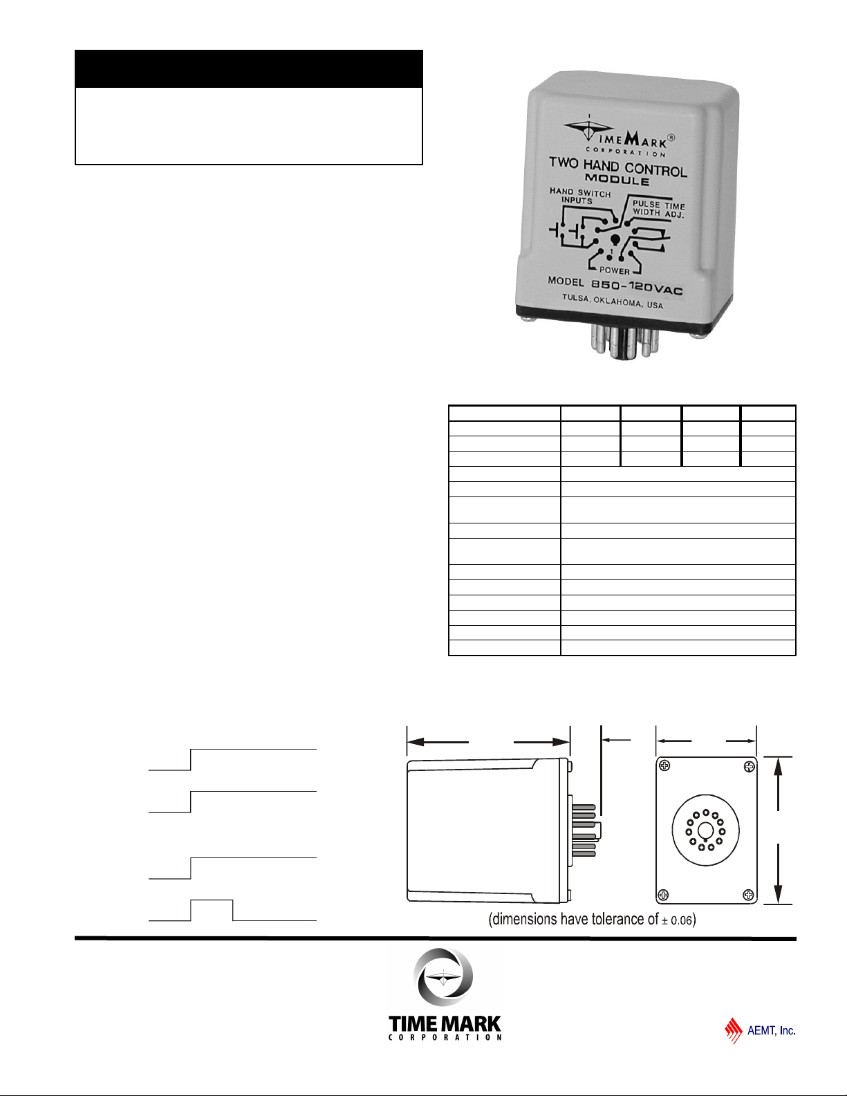
Two-Hand
Control Module
Continuous or Pulse Modes
AC or DC Versions
Socket-Mounted Design
5-Year Unconditional Warranty
DESCRIPTION
The Model 850 Two Hand Control Module is designed to be
used with two palm or pushbutton switches, which must be
closed within 0.5 seconds of each other to operate machinery.
As long as both switches are pressed, the relay will remain
energized in the continuous mode.
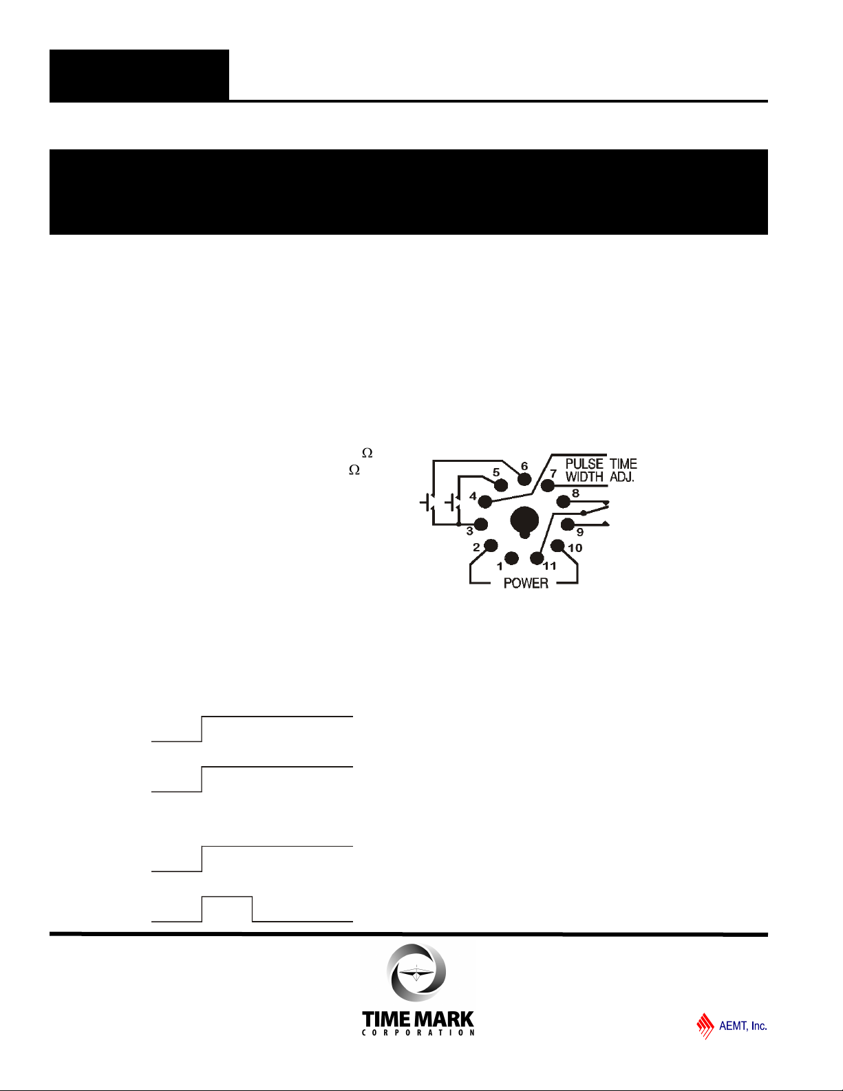
For applications requiring a pulse to initiate operations, the
Model 850 can be set to produce a pulse output by connecting
a resistor to pins 4 and 7. The resistor value in ohms should be
100,000 times the desired time in seconds (R=100,000 x T).
The internal relay de-energizes on completion of the pulse,
even if both switches are depressed. The relay de-energizes
immediately, if either hand switch is released, in standard or
pulsed mode.
The compact size of the Two-Hand Control Module allows
installation into an existing control panel. It can be used with
any type of machinery requiring safe, two-handed operation
such as presses, punches, cutters, etc. The standard nominal
supply voltages are 120VAC, 240VAC, 24VAC, 24VDC.
Other voltage versions may be available by special request.
SPECIFICATIONS
MODEL 850-120VAC 850-240VAC 850-24VAC 850-24VDC
Supply Voltage 120VAC 240VAC 24VAC 24VDC
Max. Input Voltage 135VAC 265VAC 28VAC 28VDC
Min. Input Voltage 105VAC 215VAC 22VAC 22VDC
Power Consumption 2W
Transient Protection 2500V FOR 10ms
Pulse Time/Resistance Minimum: 50ms/5K ohms
Maximum: 10 sec/1 megohm
Input Switch Resistance 100 ohms max.
Expected Relay Life Mech: 10 million operations
Elec: 100,000 operations at rated load
Contact Rating SPDT 10A at 240VAC resistive
Operating Temperature - 20º to +131º F
Humidity Tolerance 0 - 97% w/o condensation
Case Material ABS plastic
Weight 5 oz.
Mounting 11-pin socket (*not included)
* order 11-pin socket number 51X016
OPERATIONS
DIMENSIONS
11/2011
© 2011 TIME MARK CORPORATION
MODEL 850
Both Hand
Switches-CLOSED
Output
STANDARD OPERATION (without resistor)
PULSED OUTPUT OPERATION (with resistor)
Output
Both Hand
Switches-CLOSED
TIME MARK is a division of
Two-Hand Control Module
READ ALL INSTRUCTIONS BEFORE INSTALLING, OPERATING OR SERVICING THIS DEVICE.
KEEP THIS DATA SHEET FOR FUTURE REFERENCE
POTENTIALLY HAZARDOUS VOLTAGES ARE PRESENT AT THE TERMINALS OF THE MODEL 850.
ALL ELECTRICAL POWER SHOULD BE REMOVED WHEN CONNECTING OR DISCONNECTING WIRING.
THIS DEVICE SHOULD BE INSTALLED AND SERVICED BY QUALIFIED PERSONNEL.
Installation Instructions
INSTALLATION
Mount the module’s socket in a suitable enclosure.
Connect AC operating power, two switches and the
load to the appropriate socket terminals referring to the
pin diagram.
For pulsed operation– Install a resistor across
terminals 4 and 7. The resistor should be 100k for
each 1 second of delay required (example: 50k for a
0.5 second delay).
Install the module in the socket and apply power.
NOTE: When installing the Model 850 Module in areas of
high humidity or contamination, it is recommended that the
base area and all exposed metal parts of the socket be
coated liberally with a good quality silicone grease, such as
Dow Corning DC-4 or DC-4X. Insert the unit into the socket
and wipe off excess grease around the base. This will prevent
the entrance of moisture and other contaminates into the
base and socket areas.
OPERATIONS
GENERAL SAFETY
PIN CONNECTIONS
The Model 850 Two Hand Control Module requires a
standard 11-pin socket for mounting and uses a
standard pin configuration. Refer to the pin diagram
below, or on the control module for pin connections.
PIN DIAGRAM
TROUBLESHOOTING
Should the Model 850 fail to operate properly, check
that the operating voltage is present and of the correct
level. Check all fuses and verify that all wiring
connections are correct. Should problems persist,
contact the manufacturer for assistance.
WARRANTY
This product is warranted to be free from defects in
materials and workmanship, and is covered by our
exclusive 5-year Unconditional Warranty. Should
this device fail to operate for any reason, we will repair
it for five years from the date of manufacture. For
complete warranty details, see the Terms and
Conditions of Sales page in the front section of the
Time Mark catalog or contact Time Mark at 1-800-862-
2875.
Shows No Power
Applied
11/2011
© 2011 TIME MARK CORPORATION
 Loading...