

Time Mark 663 Data Sheet
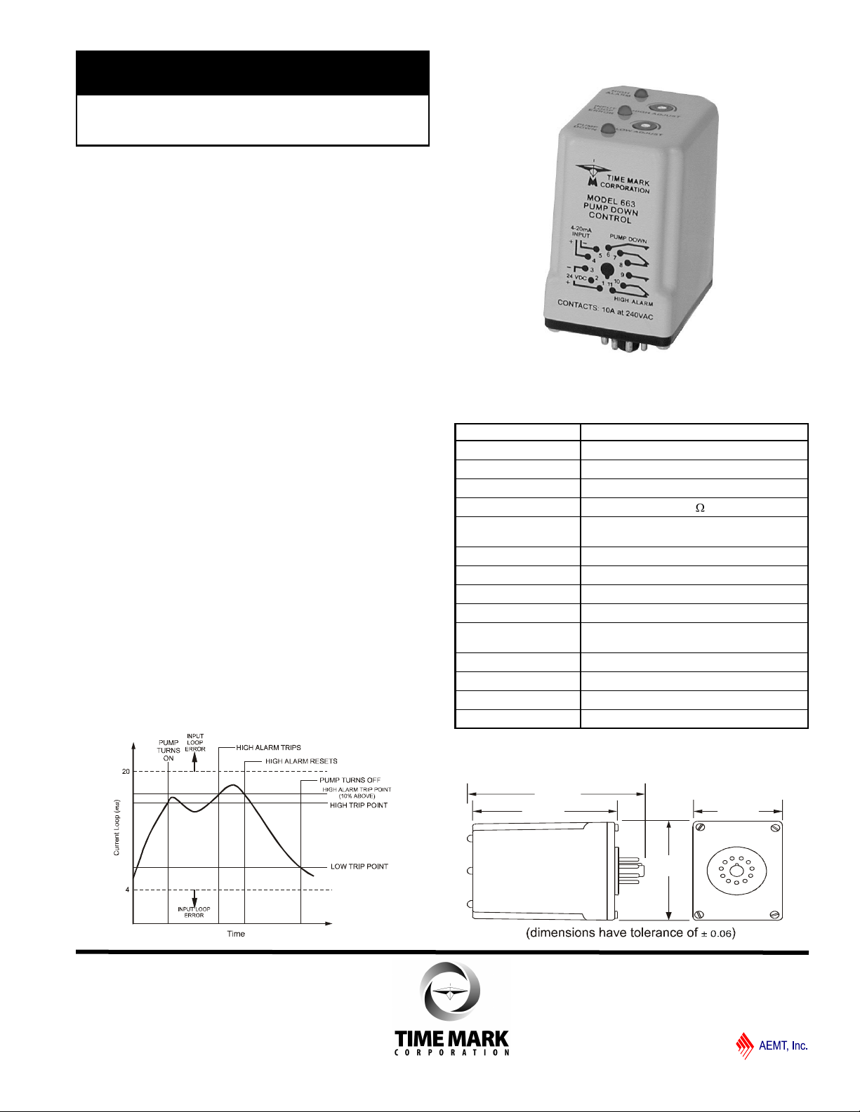
MODEL 663
2.88”
2.44”
1.75”
3.52”
TIME MARK is a division of
Pump Down Control
Automatic Reset
Two Adjustable Trip Points
5-Year Unconditional Warranty
DESCRIPTION
The Model 663 Pump Down Control, part of the 600 series
line of instrumentation controls, is designed to monitor and
maintain liquid levels. A user-provided 4-20mA current loop
represents the liquid level.
The HIGH ADJUST setpoint, and the LOW ADJUST setpoint,
are field adjustable. If the input rises above the high setpoint,
the PUMP DOWN relay energizes, and remains that way until
the input falls below the low set point.
Top-mounted LEDs on the Model 663 show system status.
The PUMP DOWN LED turns ON when the input is above the
high setpoint, and goes OFF when the input is below the low
setpoint. The HIGH ALARM condition indicator turns ON if the
input rises to 10% above the high setpoint. The HIGH ALARM
condition then resets when the input is again less than 10%
above the high setpoint.
For proper operation, the high setpoint must always be set
above the low setpoint. An INPUT LOOP ERROR LED turns
ON if the input is outside the 4-20mA range.
A Time Mark Model 650 Loop Power Supply (or equivalent) is
required to provide the 24VDC operating voltage. Also, a
Time Mark Model 672-15 Pressure Transducer (or equivalent)
is required to provide the input signal.
OPERATION DIAGRAM
SPECIFICATIONS
Model 663
Operating Voltage 24VDC ±5%
Supply Current 30mA maximum
Input Signal 4-20mA
Input Resistance
Input Loop Error
Adjustments 4-20mA
Low Alarm Trip Point 10% below low trip point
Contact Rating SPDT 10 amps at 240VAC
Operating Temp -13º to +122º F
Expected Relay Life Mech: 10 million operations
Humidity Tolerance 0-97% w/o condensation
Enclosure Material ABS plastic
Weight 6 oz.
Mounting 11-pin socket (*order separately)
High: 23-25mA
Low: 2-3mA
Elec: 100,000 at rated load
* Order 11-pin socket number 51X016
50
DIMENSIONS
01/2012
© 2012 TIME MARK CORPORATION
_
+
4-20
INPUT
ma
+
_
24 VDC
HIGH ALARM
PUMP DOWN
4
5
6
7
8
9
10
11
1
2
3
MODEL 663
TIME MARK is a division of
Pump Down Control
READ ALL INSTRUCTIONS BEFORE INSTALLING, OPERATING OR SERVICING THIS DEVICE.
KEEP THIS DATA SHEET FOR FUTURE REFERENCE.
GENERAL SAFETY
THE MODEL 663 PUMP DOWN CONTROL IS NOT TO BE USED WITH INPUT VOLTAGES OTHER THAN
24VDC. ALL ELECTRICAL POWER SHOULD BE REMOVED WHEN CONNECTING OR DISCONNECTING
WIRING. THIS DEVICE AND WIRING SHOULD BE INSTALLED AND SERVICED BY QUALIFIED PERSONNEL.
Installation Instructions
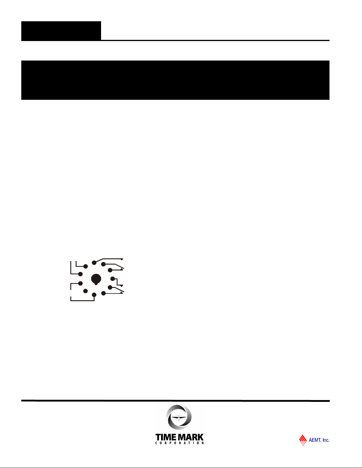
INSTALLATION
Connect 24 VDC power to pins 1 and 3 on the 11-pin socket.
Connect the 4-20mA input signal to pins 4 and 5, and the
other pins to the appropriate units in your loop system,
following the base diagram shown on the Model 663 unit (and
on this data sheet). When using separate supplies for 4-20mA
and 24VDC you must connect pins 3 and 5 together. Pay
careful attention to polarity.
NOTE: When installing the Model 663 in areas of high
humidity or contamination, it is recommended that the base
area and all exposed metal parts of the socket be coated
liberally with a good quality silicon grease, such as Dow
Corning DC-4 or DC-4X. Insert the unit into the socket and
wipe off excess grease around the base. This will prevent the
entrance of moisture and other contaminates into the base
and socket areas.
PIN DIAGRAM
ADJUSTMENT PROCEDURE
The Model 663 Pump Down Control relays are normally deenergized. If the input rises above the HIGH TRIP POINT, the
pump relay energizes, and the PUMP DOWN LED is lit.
If the input rises above the HIGH ALARM trip point (10%
above the HIGH TRIP POINT), the high alarm relay energizes
and the HIGH ALARM LED illuminates.
If the input returns to a level below the HIGH ALARM trip
point, the high alarm relay de-energizes, but the pump relay
remains energized until the input falls below the LOW TRIP
POINT (see Operation Diagram). The PUMP DOWN and
HIGH ALARM LEDs may be used to indicate the tripped
condition in the following adjustments.
Before Adjustment: For each application, you must select
the setpoints for the HIGH TRIP (the level at which you want
the pump to start pumping) and the LOW TRIP (the level
below which you do not want the pump to operate). These
two setpoints, in mA, are used to adjust the Model 663. The
HIGH ALARM trip is an internal function of the device which is
set approximately 10% above the HIGH TRIP.
To Begin: Turn both the HIGH ADJUST and the LOW
ADJUST fully counter-clockwise, to their highest settings. Both
PUMP DOWN and HIGH ALARM LEDs should be out.
To adjust the HIGH TRIP: With the Model 680 4-20mA
Simulator (or other adjustable, known signal source), apply the
current level for the HIGH TRIP. Turn the LOW ADJUST pot
fully counter-clockwise. Then, slowly turn the HIGH ADJUST
pot counter-clockwise, until the PUMP DOWN LED
illuminates.
To Adjust the LOW TRIP: With the Model 680 4-20mA
Simulator (or other adjustable, known signal source), apply the
current level for the LOW TRIP. Turn the LOW ADJUST pot
slowly clockwise until the PUMP DOWN LED goes out.
Check Setpoints: With the Model 680 4-20mA Simulator (or
other adjustable, known signal source), check the high and
low trip points and the HIGH ALARM setpoint by applying
current levels above and below the chosen setpoints, noting
the current values shown when the LEDs come on or go out.
Input Loop Error: Check the INPUT LOOP ERROR function
by applying current levels above and below the 4-20mA
range. The INPUT LOOP ERROR LED should illuminate
when current is above 20mA or below 4 mA.
WARRANTY
This product is warranted to be free from defects in materials
and workmanship, and is covered by our exclusive 5-year
Unconditional Warranty. Should this device fail to operate
for any reason, we will repair it for five years from the date of
manufacture. For complete warranty details, see the Terms
and Conditions of Sales page in the front section of the Time
Mark catalog or contact Time Mark at 1-800-862-2875.
01/2012
© 2012 TIME MARK CORPORATION
 Loading...