

Time Mark 451 Data Sheet
MODEL 451
1
2 3
4
5
6
7
8
GND
4-20mA+24VDC
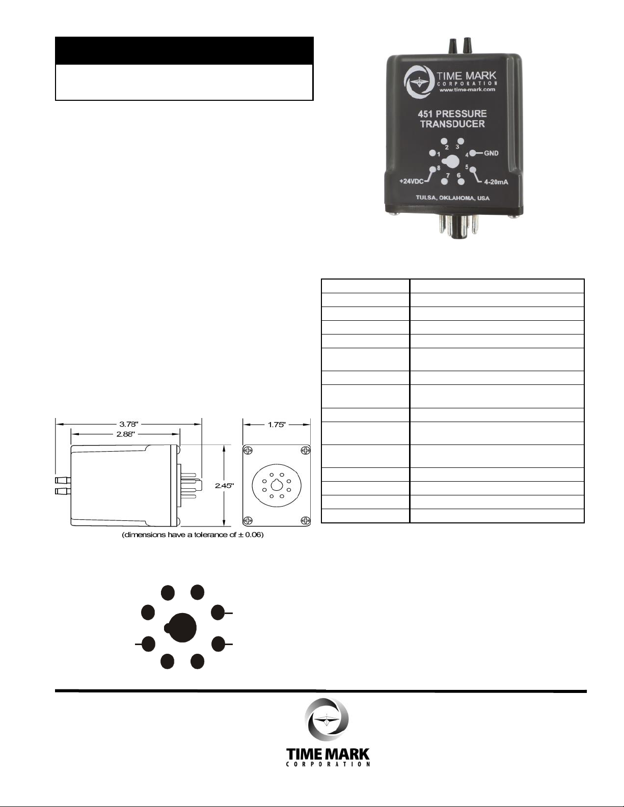
Pressure Transducer
⚫ 0-15 PSI air pressure input
⚫ 4-20mA output
⚫ Bubbler type system
⚫ Can be used with any controller
requiring a 4-20mA input
⚫ 5 Year Unconditional Warranty
⚫ Engineered and Built in the U.S.A.
DESCRIPTION
The Model 451 pressure transducer will convert
0-15psi to proportional 4-20mA signal. It can be used
with any pump control system that utilizes a
4-20mA input for level control. The 451 can be
mounted in a standard 8-pin octal socket for remote
use.
DIMENSIONS
SPECIFICATIONS
Model 451
Input voltage 24VDC
Power consumption 1 watt maximum
Air pressure input 0 to 15 psi
Max. air pressure 58 psid
Input air supply
fitting
Repeat accuracy ±1%
Signal output 4-20mA proportional to 0-15 psi
(in water; 0-15 psi = 0-34.6 feet at +77° F)
Max. load resistance 500 ohms
Compensated
temperature
Operating
temperature
Humidity tolerance 0-97% w/o condensation
Case material NORYL plastic
Termination *8-pin octal socket
Weight 3 oz.
requires 3/16” i.d. tubing
32° to +158° F
-13° to +158° F
*Order 8-pin socket number 51X120
PIN DRAWING
INSTALLATION
Mount the Model 451 in a suitable enclosure. An 8-pin
socket (Model 51X120) and a NEMA-1 rated enclosure,
designed for socket-mounted devices (Model ENC-1)
are available from Time Mark.
Connect the wiring as shown on the pin drawing or the
front of the unit.
Connect a 3/16” I.D. tubing to the input air supply fitting
09/2020
© 2020 TIME MARK CORPORATION
MODEL 451
Wet
Well
Air
Pump
Model
450
READ ALL INSTRUCTIONS BEFORE INSTALLING, OPERATING OR SERVICING THIS DEVICE.
Pressure Transducer
KEEP THIS DATA SHEET FOR FUTURE REFERENCE.
GENERAL SAFETY
POTENTIALLY HAZARDOUS VOLTAGES ARE PRESENT AT THE TERMINALS OF THE MODEL 451.
ALL ELECTRICAL POWER SHOULD BE REMOVED WHEN CONNECTING OR DISCONNECTING WIRING.
THIS DEVICE SHOULD BE INSTALLED AND SERVICED BY QUALIFIED PERSONNEL.
Installation Instructions
INSTALLATION (cont’d)
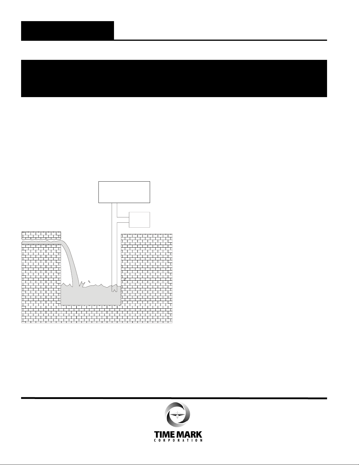
Connect a 3/16” I.D. tubing to the input air supply fitting
on the top of the unit. No connection is required on the
reference fitting. Connect the other end of the tubing to
the air compressor and the tank or well
(see figure 1).
Figure 1 Model 451 Application
Model
451
TROUBLESHOOTING
Should the Model 451 Pressure Transducer fail to
operate, check the power supply connections, making
sure that the polarity and voltage levels are correct.
Verify that all electrical connections are firmly attached
to the terminals. Check the full length of the air hose
and hose connections, to ensure there are no pressure
leaks. Connect a known pressure source to the INPUT
connection, while measuring the output current from
pins 5 and 4. The output current must have a complete
circuit through the controller, returning to the pressure
transducer. Should problems persist, contact the factory
for assistance.
WARRANTY
This product is warranted to be free from defects in
materials and workmanship, and is covered by our
exclusive 5-year Unconditional Warranty. Should this
device fail to operate for any reason, we will repair it for
five years from the date of manufacture. For complete
warranty details, see the Terms and Conditions of Sales
page in the front section of the Time Mark catalog or
contact Time Mark at 1-800-862-2875.
09/2020
© 2020 TIME MARK CORPORATION
 Loading...