

TIME MARK is a division of
4.25"
7
.
0
"
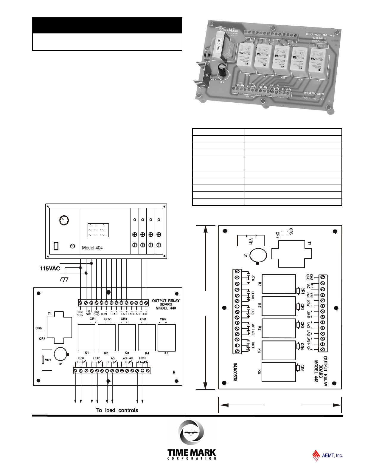
MODEL 448
Output Relay Board
Use with Models 404 & 408
5 Electromechanical Relay Contacts
DESCRIPTION
The Model 448 Output Relay Board provides electromechanical
relay contacts for the Model 404 or 408 Liquid Level Sensors,
allowing those models to be used as a control device.
The Model 448 consists of a power supply and five relays on the
surface-mounted printed circuit board. Four of the five relays are
used with the Model 404. All five relays are used on the Model
408, refer to the typical application.
Some liquid level control applications may not require the
alternating control, HOA switches, or run-time meters (see the
Model 403 or Model 407 data sheets).
The Model 404 and Model 408 Liquid Level Sensors uses the
Model 448 to meet the needs of direct relay control applications.
TYPICAL APPLICATION - Model 404
SPECIFICATIONS
Model 448
Input Voltage 105 to 130VAC
Input Frequency 47 to 65Hz
Power Consumption
Inputs
Outputs 5 SPDT
Output Rating 10 Amps at 240VAC resistive
Dimensions
Mounting Dimensions
Weight
Solid-state from Models 404 or 408
1.5W
or any contact closure
7”×4.25”×2”
6.625” × 3.875”
12.5 oz.
DIMENSIONS
11/2011
© 2011 TIME MARK CORPORATION
TIME MARK is a division of
MODEL 448
Output Relay Board
READ ALL INSTRUCTIONS BEFORE INSTALLING, OPERATING OR SERVICING THIS DEVICE.
KEEP THIS DATA SHEET FOR FUTURE REFERENCE.
GENERAL SAFETY
POTENTIALLY HAZARDOUS VOLTAGES ARE PRESENT AT THE TERMINALS OF THE MODEL 448.
ALL ELECTRICAL POWER SHOULD BE REMOVED WHEN CONNECTING OR DISCONNECTING WIRING.
THIS DEVICE SHOULD BE INSTALLED AND SERVICED BY QUALIFIED PERSONNEL.
Installation Instructions
INSTALLATION
Mount the sensor Model 404/408 Liquid Level Sensor in a suitable
enclosure.
Mount the Model 448 relay module in a suitable enclosure, near the
Sensor assembly.
The terminals marked LIQUID LEVEL on the sensor assembly are the
4-20mA output.
If used, connect these terminals to the appropriate control circuitry.
They are not connected to the relay module. Observe Polarity.
Connect a 3/16” I.D. tubing to the air supply fitting on the back of the
Model 404/408. Connect the other end of the tubing to the air
compressor and the tank air tubes.
Apply operating power and proceed to the ADJUSTMENT procedure.
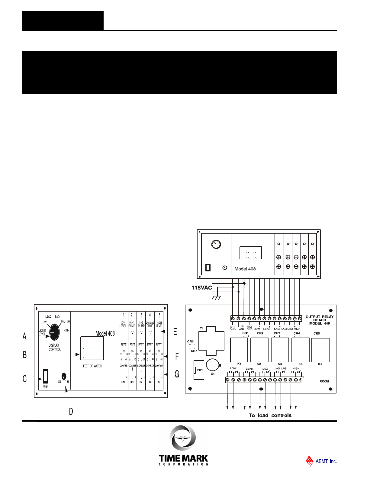
ADJUSTMENT
The trip points are set using COARSE and FINE adjustment pots; the
results are shown on the LED display.
To adjust the device, set the DISPLAY CONTROL knob (A) to LOW
and adjust the LOW LEVEL-COARSE adjustment (F) to the
approximate desired level.
The FINE adjustment (G) is located below the COARSE adjustment.
The trip level will be shown on the digital display (B).
Repeat these adjustments for the LEAD, LAG, LAG-LAG (Model 408
only) and the HIGH LEVEL adjustments.
Set the DISPLAY CONTROL knob to the LIQUID LEVEL position.
The Sensor is now ready to operate.
TROUBLESHOOTING
This device is not a field repairable unit. Should the unit not operate
properly during adjustment or testing procedure, insure that all
electrical connections and the air pressure are correct.
Verify that the proper voltage is applied and check all fuses. Contact
the factory should the unit fail during use.
WARRANTY
This product is warranted to be free from defects in materials and
workmanship for one year. Should this device fail to operate, we will
repair it for one year from the date of manufacture. For complete
warranty details, see the Terms and Conditions of Sales page in the
front section of the Time Mark catalog or contact Time Mark at 1-800-
862-2875.
TYPICAL APPLICATION - Model 408
11/2011
© 2011 TIME MARK CORPORATION
 Loading...